

Lennox ECB21-12.5-1P, ECB21, ECB21-20.0-1P, ECB21-25.0-1P, ECB21-30.0-1P Installation Instructions Manual
...Page 1
Supersedes 502,704M
ELECTRIC UNITS ECB21 SERIES HEATERS
INSTALLATION INSTRUCTIONS FOR ECB21 SERIES ELECTRIC
HEAT SECTIONS USED IN B21/CB21/CBH21 APPLICATIONS
503,018M
9/93
I--SHIPPING AND PACKING LIST
Package 1 of I contains:
1-- Assembled electric heat section
1- - Filler plate for use with:
ECB21- -5.0- -1P,ECB21- -6.0- -1P,
ECB21- -7.0- -1P,ECB21--8.0- -1P,
ECB21- -10.0- -1P, ECB21- -20.0- -1P
2-- Wiring diagram stickers
II--SHIPPING DAMAGE
Check heater forshipping damage. The receiving party
should contact the last carrier immediately ifany dam-
age is found.
Ill--GENERAL
These instructions are intended as a general guide
and do not supersede local or national codes in any
way. Authorities having jurisdiction should be con-
sulted before installation.
IV--REQUIREMENTS
Installation of Lennox blower coil units with electric heat
must conform with standards in National Fire Protection
Association (NFPA) "Standard for Installation of Air
Conditioning and Ventilating Systems NFPA No. 90A,"
"Standard for the Installation of Residence- -Type Warm
Air Heating and Air Conditioning Systems NFPA No.
90B," manufacturer's installation instructions and local
municipal building codes.
This unit is approved for installation clearances to com-
bustible materials as listed on the unit heater installed
nameplate located on the blower coil unit. Accessibility
and service clearances must take precedence over
combustible material clearances.
,& WARNING
V- -APPLICATION
ECB21 series heaters are designed to provide field
installed electric heat for B21 blower units and CB21
and CBH21 series blower coil units.
_]_rat Ical _1993 Lennox Industires Inc.
ure Page 1
Page 2

VI--INSTALLATION
NOTE--If replacing an existing electric heat section, dis-
connect and remove the existing heat section and wiring.
1- - Disconnect power to B21!CB21/CBH21 unit.
2-- Remove blower access panel.
3-- Remove circuit breaker knockout on blower/blow-
er coil access cover in applications using an
ECB21 12.5, 15.0, 20.0, 25.0 or 30.0--Y, --P volt-
age heater in a CB/CBH21--41 or B/CB21--51/65
unit (See figure 1).
KNOCKOUTS IN B/CB/CBH21 UNIT
ACCESS PANEL
I
CB/CBH21--41
REMOVE LARGER KNOCKOUT FOR USE WITH
ECB21-q5.0--1Y HEATER; REMOVE BOTH KNOCKOUTS
IF ECB21--12.5/15.0/20.0--1P HEATERS ARE USED.
B/CB21 - -51/65
4-- Remove blank filler plate(s) in control box.
5-- Adjust circuit breaker mounting bracket according
to B21/CB21/CBH21 application. Bracket adjusts
forward by removing mounting screws, reposition-
ing bracket and reinserting screws (See figure 2).
6- - Slide ECB21 heat section into opening. Hole(s) on
each side of ECB21 line up with holes in control
box (See figure 3). Reinstall screws to secure heat
assembly. On the following ECB21 heaters, circuit
breakers line up with the opening in the access
cover: ECB21 12.5, 15.0, 20.0, 25.0 and 30.0 kwY
and P voltage heaters.
7- - When installing 5.0, 6.0, 7.0, 8.0, 10.0 and 20.0 kw
P voltage heaters; 5.0, 7.5, 10.0 and 15.0 kw Y volt-
age heaters in CB/CBH21--41 or B/CB21--51/65
units, a filler plate(s) (provided) must be used to
seal the element opening (See figures 3 and 4).
FILLER PLATE
VESTIBULE PANEL
ECB21--15.0--1Y HEATER IS USED.
REMOVE ALL THREE KNOCKOUTS IF ECB21- -25.0/30.0- -1P
OR ECB21--20.0/25.0--1Y HEATERS ARE USED.
FIGURE 1
ECB21 IN CB/CBH21--41
CIRCUIT BREAKER POSITION
ECB21 IN B/CB21--51/65
CIRCUIT BREAKER POSITION
ECB21 ELEMENT _.j
ASSEMBLY
UPPER
FILLER
PLATE\
I
I
f
OPENING
IN 51/65
_L
I
FIGURE 3
FILLER
PLATE
\
ECB21 ELEMENT
FACE PLATE
OPENING
21/26/31/41
VESTIBULE
PANEL
UPPER
FILLER
IN
Page 2
ECB21* q5.0**lP
FACEPLATE
FIGURE 4
BLOWER
DECK
Page 3
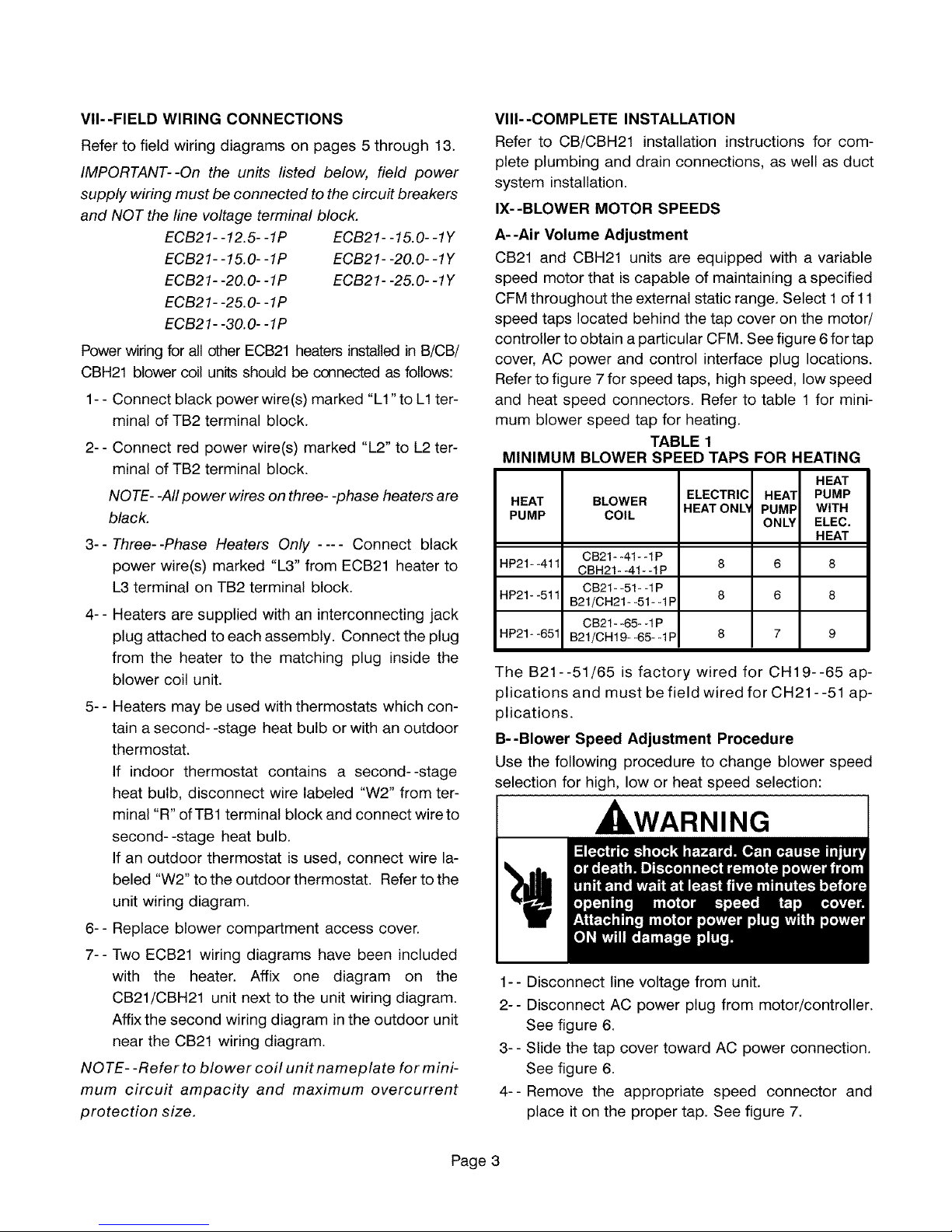
VII--FIELD WIRING CONNECTIONS
Refer to field wiring diagrams on pages 5 through 13.
IMPORTANT--On the units listed below, field power
supply wiring must be connected to the circuit breakers
and NOT the line voltage terminal block.
ECB21- -12.5- -1P ECB21- -15.0- -1Y
ECB21- -!5.0- -1P ECB21- -20.0- -1Y
ECB21- -20.0- -1P ECB21- -25.0- -1Y
ECB21- -25.0- -1P
ECB21- -30.O--1P
Power wiring for all other ECB21 heaters installed in B/CB/
CBH21 blower coil units should be connected as follows:
1- - Connect black power wire(s) marked "L1 "to L1 ter-
minal of TB2 terminal block.
2-- Connect red power wire(s) marked "L2" to L2 ter-
minal of TB2 terminal block.
NOTE- -All power wires on three- -phase heaters are
black.
3--Three--Phase Heaters Only .... Connect black
power wire(s) marked "L3" from ECB21 heater to
L3 terminal on TB2 terminal block.
4-- Heaters are supplied with an interconnecting jack
plug attached to each assembly. Connect the plug
from the heater to the matching plug inside the
blower coil unit.
5-- Heaters may be used with thermostats which con-
tain a second--stage heat bulb or with an outdoor
thermostat.
If indoor thermostat contains a second--stage
heat bulb, disconnect wire labeled "W2" from ter-
minal "R" ofTB1 terminal block and connect wire to
second--stage heat bulb.
If an outdoor thermostat is used, connect wire la-
beled "W2" to the outdoor thermostat. Refer to the
unit wiring diagram.
6-- Replace blower compartment access cover.
7-- Two ECB21 wiring diagrams have been included
with the heater. Affix one diagram on the
CB21/CBH21 unit next to the unit wiring diagram.
Affix the second wiring diagram in the outdoor unit
near the CB21 wiring diagram.
NO TE- -Refer to blower coil unit namepla te for mini-
mum circuit ampacity and maximum overcurrent
protection size.
VIII--COMPLETE INSTALLATION
Refer to CBiCBH21 installation instructions for com-
plete plumbing and drain connections, as well as duct
system installation.
IX--BLOWER MOTOR SPEEDS
A--Air Volume Adjustment
CB21 and CBH21 units are equipped with a variable
speed motor that is capable of maintaining a specified
CFM throughout the external static range. Select 1 of 11
speed taps located behind the tap cover on the motor/
controller to obtain a particular CFM. See figure 6 for tap
cover, AC power and control interface plug locations.
Refer to figure 7 for speed taps, high speed, low speed
and heat speed connectors. Refer to table 1 for mini-
mum blower speed tap for heating.
TABLE 1
MINIMUM BLOWER SPEED TAP,'
HEAT
PUMP
HP21- -411
HP21* -511
HP21* -651
BLOWER
COIL
CB21- -41- -1P
CBH21- -41- -1P
CB21- -51- -1P
B21/CH21- -51- -1P
CB21- -65- -1P
B21/CH 19- -65- -1P
ELECTRIC
HEAT ONL_
FOR HEATING
HEAl"
PUMP
ONLY
8
8
8
HEAT
PUMP
WITH
ELEC.
HEAT
6 8
6 8
7 9
The B21--51/65 is factory wired for CH19--65 ap-
plications and must be field wired for CH21 --51 ap-
plications.
B--Blower Speed Adjustment Procedure
Use the following procedure to change blower speed
selection for high, low or heat speed selection:
, WARNING
1-- Disconnect line voltage from unit.
2-- Disconnect AC power plug from motor/controller.
See figure 6.
3-- Slide the tap cover toward AC power connection.
See figure 6.
4--Remove the appropriate speed connector and
place it on the proper tap. See figure 7.
Page 3
Page 4
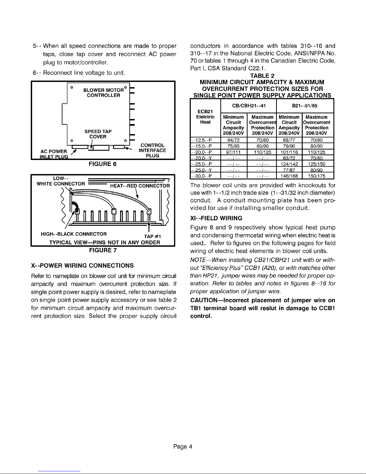
5--Whenallspeedconnectionsaremadetoproper
taps,closetap coverand reconnectACpower
plugtomotor!controller.
6--Reconnectlinevoltagetounit.
o %oo .o%OR°-
E
Io o-
FIGURE 6
LOW- -
WHITE CONNECTOR _ HEAT--RED CONNECTOR
HIGH--BLACK CONNECTOR TAP #1
TYPICAL VIEW--PINS NOT IN ANY ORDER
FIGURE 7
X--POWER WIRING CONNECTIONS
Refer to nameplate on blower coil unit for minimum circuit
ampacity and maximum overcurrent protection size. If
single point power supply is desired, refer to nameplate
on single point power supply accessory or see table 2
for minimum circuit ampacity and maximum overcur-
rent protection size. Select the proper supply circuit
CONTROL
INTERFACE
PLUG
= = I"
conductors in accordance with tables 310--16 and
310--17 in the National Electric Code, ANSl/NFPA No.
70 or tables 1 through 4 in the Canadian Electric Code,
Part I, CSA Standard C22.1.
TABLE 2
MINIMUM CIRCUIT AMPAClTY & MAXIMUM
OVERCURRENT PROTECTION SIZES FOR
SINGLE POINT POWER SUPPLY APPLICATIONS
CB/CBH21- -41 B21- -51/65
ECB21
Elelctric Minimum Maximum Minimum Maximum
Heat Cirucit Overcurrent Cirucit Overcurrent
Ampacity Protection Ampacity Protection
208/240V 208/240V 208/240V 208/240V
--12.5--P 64/72 70/80 68/77 70/80
- -15.0- -P 75/85 80/90 79/90 80/90
--20.0--P 97/11t 110/125 101/116 110/125
- -20 O- -Y - - 1 .... / - - 63/72 70/80
- -25.0- -P -- / .... /-- 124/142 125/150
- -25.0- -Y - - / .... 1- - 77/87 80/90
- -30.0- -P -- / .... /-- 146/168 150/175
The blower coil units are provided with knockouts for
use with 1- -1/2 inch trade size (1- -31/32 inch diameter)
conduit. A conduit mounting plate has been pro-
vided for use if installing smaller conduit.
XI--FIELB WIRING
Figure 8 and 9 respectively show typical heat pump
and condensing thermostat wiring when electric heat is
used,. Refer to figures on the following pages for field
wiring of electric heat elements in blower coil units.
NOTE--When installing CB21/CBH21 unit with or with-
out "Efficiency Plus" CCB1 (A20), or with matches other
than HP21, jumper wires maybe needed for proper op-
eration. Refer to tables and notes in figures 8--16 for
proper application of jumper wire.
CAUTION--Incorrect placement of jumper wire on
TB1 terminal board will reslut in damage to CCB1
control.
Page 4
Page 5
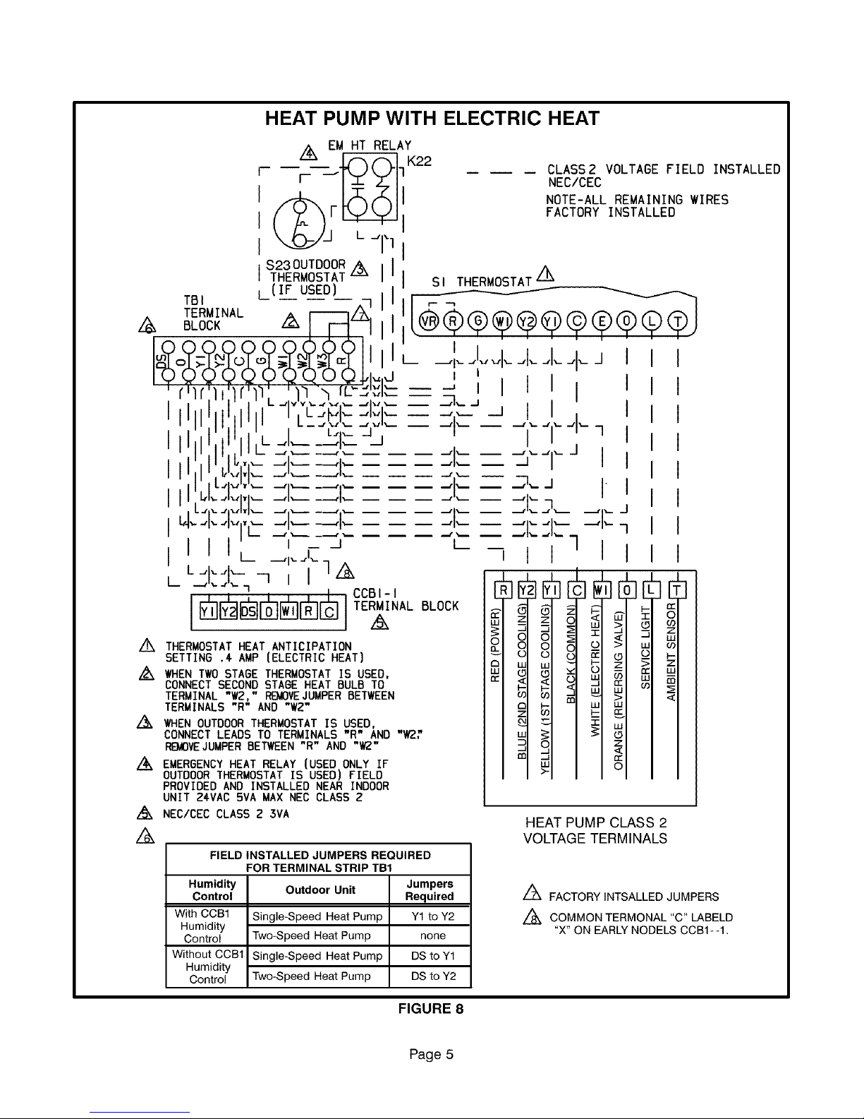
HEAT PUMP WITH ELECTRIC HEAT
Z__ EM HT RELAY
_ _ K22
r- --r'-z'-./i1
CLASS2 VOLTAGE FIELD INSTALLED
NEC/CEC
NOTE-ALL REMAINING WIRES
FACTORY INSTALLED
S23 OUTDOOR
THERMOSTAT I-Y-_ II s, THERMOSTAT z_
(IF USED) _ _
TBI -- -- -- ;q _(_ _v._ 1
( I '
ot;t to'ot ,- -,,,,,,,,,,-_,k_,,,__+_,,
I_)L)_( ..(.r)(,,2q (,-)(.,.).P,.,d _ '
:rilr.lt:lr 1. :/"_", rL'-d':_I_--- _ ! I i i I '
I I I I i"1","C-_i_.;:_1",'1_= _'_" - I I I
,ll ; _- "z"_ -_";'- -- -1'- -- -"- -"--'1"--1
I II I' ' ,-_.,.,___--q.,I .--, i ' . •
I it -I .... _ .... ,,-",.-- -- .--"--',',-.J I ,
i,,,._._,,____.,_____.,___ j I I I
] I I'L,I,_..,I,,.,,,_--..,I,----.., .... _,l,_ J _,,_ n I .
. iI.,,...,,,I,,I,_ ....,,.____.,. ..... ,,__ __ ._,I,_._,_ .__,,_ J
_-I,--4,--,I,,,',.- -"1"--- ----.,I'- -- -- -- -...,i'- -- -" ,--"'1"- -...'1'--n
I I I IL --,_.L- _ I I I
I _-J L /
"1__ i CCBI-I UUIY; IYII ;J U U J J
I F;_ll'JJ'_-_ll-_'IF_T]F'_"IF'_-llTERMINAL BLOCK _ _ _--
'_JUL_J_JL._JL_JL_JL._J _ _I z
z_ THERMOSTAT HEAT ANTICIPATION 0 _I _I
SETTING .'€AMP (ELECTRIC HEAT) _ ,o,Io,I
Z_ WHEN TWO STAGE THERMOSTAT IS USED, _: _1 61
cONNECT SECOND STAGE HEAT BULB TO _-I_<1
TERMINAL W2, RB_IOVE.JUMPERBETWEEN _
TERMINALS"R"AND
/_ IHENOUTDOORTHERMOSTATIS USED, . q q
CONNECT LEADS TO TERMINALS "R AND W2," _1 _1
RE_VEJUMPERBETWEEN"R"AND"_" al OI
Z_ EMERGENCYHEATRELAY(USEDONLYIF _l _l
OUTDOOR THERMOSTAT IS USED] FIELD I >I
PROVIDED AND INSTALLED NEAR INDOOR
UNIT Z&VAC BVA MAX NEC CLASS 2
Z_ NEC/CEC CLASS 2 3VA HEAT PUMP CLASS 2
Z_ VOLTAGE TERMINALS
FIELD INSTALLED JUMPERS REQUIRED
FOR TERMINAL STRIP TB1
Humidity
Control
With COB1
Humidity
Control
Without CCBt
Humidity
Control
Outdoor Unit
Single-Speed Heat Pump
Two-Speed Heat Pump
Single-Speed Heat Pump
Two-Speed Heat Pump
Jumpers
Required
Y1 to Y2
none
DS to Y1
DS to Y2
Z_ FACTORY INTSALLED JUMPERS
Z_ COMMON TERMONAL "C" LABELD
"X" ON EARLY NODELS CCB1 - -1.
FIGURE 8
Page 5
Page 6

COOLING APPLICATION WITH ELECTRIC HEAT
,N
TRANSFORMER
NOTE-USE COPPER
CONDUCTORSONLY
A15 BLOWER
DRIVE CONTROL
Ln @ @ @ HEAT ELEMENT 2
_o _ i_ LI
00===_ HE(z)
0 r_ "r_HE( I)_ 0 r_
K32 R 6
TB2
TERMINAL
BLOCK
..%
I-I _oo.' 'TB,TERMINALBOARD_
CBO LO*ERRELAY
L2 cI _ ', [I (,I (,I I I_.__ --_ (I
z0e-zsoz6o/i THE._bSTAT.--, _- "-'",'"VL_'_l__."-"1 " '
t'I'd"]I]lI I I
" _'', C"...L-----JjI' Ill I
r. -.--__J.- -_..IJ_,..vl.--JJ
i J-.
GROUND
/1,, z_
_LI
CIRCUIT2
L2
L3 Z_
I
!
VV V LINE VOLTAGE FIELD INSTALLED
,'I,,
NOTE-ALL REMAINING WIRES FACTORY INSTALLED
REFER TO UNIT RATING
PLATE FOR MINIMUM
CIRCUIT AMPACITY AND
MAXIMUM OVERCURRENT
PROTECTION SIZE
L_ TO EXTERNAL LOAD 24VAC
AT .50AMP MAXIMUM
L_ NECICEC CLASS 2 5VA
WHEN TWO STAGE THERMOSTAT
IS USED, CONNECT SECOND
STAGE HEAT BULB TO TERMINAL
"WZ," REMOVE JUMPER
BETWEEN TERMINALS
"R" AND "W2"
/,k
THERMOSTAT HEAT
ANTICIPATION SETTING
•4 AMP (ELECTRIC HEAT)
]J
CLASS 2 VOLTAGE FIELD INSTALLED L_ L3FORTHREE PHASE
NEC/CEC HEATERSONLY
L_CCBI-I L_
TERMINAL BLOCK
z_
FIELD INSTALLED JUMPERS REQUIRED
FOR TERMINAL STRIP TB1
Humidity Outdoor Unit
Control
With CCB1
Humidity
Control
Without
CCB1
Humidity
Control
/6,
FACTORY INSTALLED JUMPERS
Zk
COMMON TERMINAL "C" LABLED "X" ON
EARLY MODELS CCB1- -t.
FIGURE 9
Single-Speed
Condensing Unit
Two-Speed
Condensing Unit
Single-Speed
Condensinq Unit
Two-Speed
Condensing Unit
Jumpers
Reauired
Y1 to Y2 and
Ote R
Ote R
DS to Y1 and
Ot0 R
DS to Y2 and
Oto R
Page 6
Page 7

FIELD WIRING FOR ECB21
5 KW SINGLE--PHASE HEATERS
/,_ Sl
P,®e
I I I
-_-- L_.
i I i i
i t I I /),_
F'II I
I I I
THERMOSTAT
A
TB1
TERMINAL
BOARD
.o-_o
o-_
.o-_o
-o2<:)
02-0
,ill
GROUND
K3
INDOOR BLOWER
RELAY ! J2
K32 HEAT RELAY
RESISTOR
U
/ \j
1
HE@)
U
i
TRANSFORMER
T1
P2
NOTE- -USE COPPER
CONDUCTORS ONLY
Z_TO EXTERNAL LOAD 24VAC AT .50 AMP MAXIMUM.
Z_ NEC/CEC CLASS 2 3VA
//_ SEE FIGURE 7 FOR TYPICAL HEAT PUMP T'STAT WIRING.
EMERGENCY HEAT RELAY (USED ONLY IF OUTDOOR
THERMOSTAT IS USED) FIELD- -PROVIDED AND IN- -
STALLED NEAR INDOOR UNIT. 24VAC 5VA MAXIMUM
NEC/CEC CLASS 2.
,_ THERMOSTAT HEAT ANTICIPATION SETTING .4 AMP
(ELECTRIC HEAT) Z_
//_ REFER TO JUMPER APPLICATION TABLES tN
TYPICAL HEAT PUMP OR COOLING WIRING
DIAGRAMS IN THIS INSTRUCTION.
II
CIRCUIT NO.2
L2 L1
208- -240/60/1
FIGURE 10
D
D
TB2
TERMINAL
BLOCK
RED
BLACK
LINE VOLTAGEFIELD INSTALLED
CLASS 2 VOLTAGE FIELD tNSTLLED
NEC/CEC
NOTE* *ALL OTHER
WIRES FACTORY INSTALLED
FACTORY INSTALLED JUMPERS
COMMON TERMINAL "C" LABLED "X" ON
EARLY MODELS CCB1- -1.
Page 7
Page 8

FIELD WIRING FOR ECB21 6, 7, OR 8 KW SINGLE--PHASE HEATERS
/_ S1
THERMOSTAT
r
, [-r-_- ÷ -*-_---_-J I
^ _r-'_--_, t-
/,\ I_ I ,, I
II I I L
__-I,-----.-,L----"
IL F_J'- I ""
A
TB1
TERMINAL
BOARD
_/P2 K3
INDOOR BLOWER
9 J2 RELAY
K32 HEAT RELAY
TRANSFORMER
/--\
I I
J2* -8
P2- -8 //
L_ I____ , I Z_ r"-'_
i
NOTE* *USE COPPER |
CONDUCTORS ONLY
//_TO EXTERNAL LOAD 24VAC AT .50 AMP MAXIMUM.
NEC/CEC CLASS 2 3VA
SEE FIGURE 7 FOR TYPICAL HEAT PUMP T'STAT WIRING.
EMERGENCY HEAT RELAY (USED ONLY IF OUTDOOR
THERMOSTAT IS USED) FIELD- -PROVIDED AND IN--
STALLED NEAR INDOOR UNIT. 24VAC 5VA MAXIMUM
NEC/CEC CLASS 2.
THERMOSTAT HEAT ANTICIPATION SETTING .4 AMP
(ELECTRIC HEAT)
REFER TO JUMPER APPLICATION TABLES tN
TYPICAL HEAT PUMP OR COOLING WIRING
DIAGRAMS IN THIS INSTRUCTION.
/
1
CIRCUIT NO. 2
L2 L1
208- -240/60/1
_3
LI_ BLACK BLACK
TB2
TERMINAL
BLOCK
A FACTORY INSTALLED JUMPERS
A OMMON TERMINAL "C" LABLED "X" ON
P2
X/
I \ /J2
R )
EARLY MODELS CCB1- -1.
LINE VOLTAGE FIELD INSTALLED
CLASS 2 VOLTAGE FIELD iNSTALLED
NEC/CEC
NOTE-*ALL OTHER
WIRES FACTORY INSTALLED
FIGURE 11
Page 8
Page 9

FIELD WIRING FOR ECB21 10.0 KW SINGLE--PHASE HEATER
//_ S1
THERMOSTAT
i FF4_-.--I----,-I----1 _j I BOARD
vvv I! I .[I J. _.,L,_I_
A I! J l--I--'J------ I -I---_
/l"X I I I I I I ! o
I I I I I _,L.._'I"-_ _O-_yl_
I r_-- --_
i ' I L_
1_ .... ;-_
; .......
I I' G
J i k £_:------_
I I I ]- .....
,il , i,
_F_] _CC 1._.1ERE_M_ AL_80C_K F_ Z__
B T N L
K3
INDOOR
BLOWER
RELAY
P2@
J2_/
K33 HEAT RELAY
wq
E
8 _ P2
TRANSFORMER
I T1
J2
HEg) HE(2)
@@
I
_i RED
_ BLACK BLACK
NOTE-*USE COPPER
CONDUCTORS ONLY
/k
TO EXTERNAL LOAD 24VAC AT .50 AMP MAXIMUM.
A
NEC/CEC CLASS 2
A
SEE FIGURE 7 FOR TYPICAL HEAT PUMP T'STAT WIRING.
EMERGENCY HEAT RELAY (USED ONLY IF OUTDOOR
THERMOSTAT IS USED) FIELD- -PROVIDED AND IN- -
STALLED NEAR INDOOR UNIT. 24VAC 5VA MAXIMUM
NEC/CEC CLASS 2.
z_
THERMOSTAT HEAT ANTICIPATION SETTING .4 AMP
(ELECTRIC HEAT) //_ COMMON TERMINAL "C" LABLED "X" ON
z_
WHEN TWO- -STAGE T'STAT IS USED, CONNECT
SECOND- -STAGE HEAT BULB TO TERMINAL "W2."
REMOVE JUMPER BETWEEN TERMINALS "R" AND "W2."
Z_ REFER TO JUMPER APPLICATION TABLES IN
TYPICAL HEAT PUMP OR COOLING WIRING
DIAGRAMS IN THIS INSTRUCTION.
Jl
CIRCUIT NO 2
L2 L1
208- -240/60/1
TB2
TERMINAL
BLOCK
FIGURE 12
LINE VOLTAGE FIELD INSTALLED
CLASS 2 VOLTAGE FIELD
INSTALLED NEC/CEC
NOTE-*ALL OTHER
WIRES FACTORY
INSTALLED
/%
FACTORY INSTALLED JUMPERS
EARLY MODELS CCBt- -1.
qll'
GROUND
Page 9
Page 10

FIELD WIRING FOR ECB21 12.5, 15.0 OR 20.0 KW SINGLE--PHASE HEATERS
A THERMOSTAT
A
CIRCUIT NO 2 CIRCUIT NO 3
208- _240/60/1 208* -240/60/1
L1 L2 L1 L2
I,_P2 K3 INDOOR BLOWER
J2 RELAY
J2 1(( P2
A K33 HEAT RELAY
K32 HEAT RELAY
P2-*9
/
K34 HEAT RELAY
P2
TRANSFORMER
I T1I
w w
@@@
HE(l] HE(2: HE(3] HE(4)
t
TB2 GROUND
TERMINAL
NOTE--ALL OTHER
WIRES FACTORYtNSTALLED
A TO EXTERNAL LOAD 24VAC AT .50 AMP MAXIMUM.
A NEC/CEC CLASS 2 3VA
ASEE FIGURE 7 FOR TYPICAL HEAT PUMP T'STAT WIRING.
EMERGENCY HEAT RELAY (USED ONLY IF OUTDOOR
THERMOSTAT IS USED) FIELD- -PROVIDED AND INSTALLED
NEAR INDOOR UNIT. 24VAC 5VA MAXIMUM NEC/CEC
CLASS 2.
ATHERMOSTAT HEAT ANTICIPATION SETTING .4 AMP
(ELECTRIC HEAT)
A CONNECTIONS AT TERMINALS "E" AND "X" OF THERMO-
STAT (S1) ONLY IF EMERGENCY HEAT RELAY IS USED. /_ COMMON TERMINAL "C" LABLED "X" ON
A WHEN TWO- -STAGE T'STAT IS USED, CONNECT SECOND- -
--STAGE HEAT BULB TO TERMINAL "W2." REMOVE JUMPER
BETWEEN TERMINALS "R" AND "W2."
i LINE VOLTAGE FIELD INSTALLED
A USE COPPER CONDUCTORS ONLY.
A REFER TO JUMPER APPLICATION TABLES IN TYPICAL
HEAT PUMP OR COOLING WIRING DIAGRAMS IN THIS
A INSTRUCTION.
FACTORY INSTALLED JUMPERS
/,ok
EARLY
CLASS 2 VOLTAGE FIELD INSTALLED
NEC/CEC
MODELS CCB1
BLOCK
FIGURE 13
Page 10
Page 11

FIELD WIRING FOR ECB21 25 OR 30 KW SINGLE--PHASE HEATERS
------ CLASS 2 VOLTAGE FIELD
FIELD INSTALLED
INSTALLED NEC/CEC
NOTE--ALL OTHER
WIRES FACTORYtNSTALLED
CIRCUIT NO
L1 L2
K3 INDOOR BLOWER
[]
K33 HEAT RELAY K35 HEAT RELAY
J2 P2 K32 HEAT RELAY
U
TRANSFORMER
O
Kl16 HEAT RELAY
R6
RESISTOR
HE( HE(_ _HE(8 HE(z qE(5 HE(6
O©©OO©
_T
GROUND
TO EXTERNAL LOAD 24VAC AT .50 AMP MAXIMUM.
,/_ NEC/CEC CLASS 2 3VA
SEE FIGURE 7 FOR TYPICAL HEAT PUMP T'STAT WIRING. /_
EMERGENCY HEAT RELAY (USED ONLY IF OUTDOORL&.X USE COPPERCONDUCTORS ONLY.
THERMOSTATIS USED) FIELD- -PROVIDED AND INSTALLED A
NEAR INDOOR UNIT. 24VAC 5VA MAXIMUM NEC/CEC/8 _ WHEN OUTDOOR THERMOSTAT IS USED, CONNECT LEADS
CLASS 2. TO TERMINALS "R" AND "W3" AND REMOVE JUMPER BE*
THERMOSTAT HEAT ANTICIPATION SETTING .4 AMP
A //_ TWEEN "R" AND "W3".
(ELECTRIC HEAT) PUMP OR COOLING WIRING DIAGRAMS IN THIS INSTRUCTION.
CONNECTIONS AT TERMINALS "E" AND "X" OF THERMO-/_
STAT ($1) ONLY IF EMERGENCY HEAT RELAY IS USED. /_uk FACTORY INSTALLED JUMPERS
A WHEN TWO* -STAGE T'STAT IS USED, CONNECT SECOND- A COMMON TERMINAL "C" LABLED "X" ON EARLY MODELS
STAGE HEAT BULB TO TERMINAL "W2." REMOVE JUMPEI_,..LL& CCBI* -1.
BETWEEN TERMINALS "R" AND "W2."
FIGURE 14
REFER TO JUMPER APPLICATION TABLES IN TYPICAL HEAT
Page 11
Page 12

A $1
THERMOSTAT
A
FIELD WIRING FOR ECB21 5, 7.5, 10
AND 15 Kw THREE--PHASE HEATERS
rr-_J2__L__Ji (; TER_;NAL
L_(?! I 1I t i
vv IVII I _1 L I t
II I li I-- " v
/_11 I I II I _
I I I o
-- BOARD
K3 INDOOR
BLOWER
RELAY
tl 4Li_ L_
Ill ! i L_ Y2
I_ .... OX)
I!LL .....
II / A ,_,w2,_,
I II I I I L_I_L)'-'U
7I t btz :i_
HI t I r+_O_
I I I F l_l I
NEC/CEC
NOTE**ALL OTHER WIRES FACTORY INSTALLED
A _ CIRCUIT NO 2
ECB21- 45 0--1Y ONLY _ 208_ _240/60/3
CIRCUIT NO 2 LI L2 L3
208- _240/60/3 _ _ _
L3 L2 L1 cCFB(I_T _ | i i
TRANSFORMER
j@ €)@
HE(l) HE(2) HE(3)
@@@
J
GROUND
A TO EXTERNAL LOAD 24VAC AT .50 AMP MAXIMUM.
A NEC/CEC CLASS 2 3VA
A SEE FIGURE 7 FOR TYPICAL HEAT PUMP T'STAT
WIRING. EMERGENCY HEAT RELAY (USED ONLY IF
OUTDOOR THERMOSTAT tS USED) FIELD--PRO-
VIDED AND INSTALLED NEAR INDOOR UNIT, 24VAC
5VA MAXIMUM NEC/CEC
A THERMOSTAT HEAT ANTICIPATION SETTING .4 AMP
(ELECTRIC HEAT)
A CONNECTIONS AT TERMINALS "E" AND "X" OFTHER-
MOSTAT ($1) ONLY IF EMERGENCY HEAT RELAY IS
USED.
A USE COPPER CONDUCTORS ONLY.
A REFER TO JUMPER APPLICATION TABLES IN TYPI-
A FACTORY INSTALLED JUMPERS
A OMMON TERMINAL "C" LABLED "X" ON
FIGURE 15
Page 12
CAL HEAT PUMP ORCOOLING WIRING DIAGRAMS IN
THIS INSTRUCTION.
EARLY MODELS CCB1- -1.
Page 13

FIELD WIRING FOR ECB21 20, 25 Kw THREE--PHASE HEATERS
A $1
THERMOSTAT
F@®®o®®QQI A
_t" i I / I I TBt
K3
iNDOOR BLOWER
RELAY
TRANSFORMER
A
II I I If___
L, _--t--_--q [--g2gaO
rJ ,
COB1--1 TERMINAL BLOCK A
FIELD iNSTALLED 208_-240/60/3
CLASS 2 VOLTAGE
FIELD INSTALLED
NEC/CEC
NOTE* *ALL OTHER
WIRES FACTORY
INSTALLED
CIRCUIT NO. 2
L1 L2 L3
CIRCUIT NO. 3
208* -240/60/3
L1 L2 L3
P2 _--
Ed
E
TB2
TERMINAL
BLOCK
[]
[]
[]
K33 HEAT RELAY K35 HEAT RELAY
K34 HEAT RELAY
@41-_-
HE(l: HE(2 HE(3 HE(4 4E(5) HE(6
TI
J2
/\
8
A
P2
R6
RESISTOR
7
A TO EXTERNAL LOAD 24VAC AT .50 AMP MAXIMUM.
A NEC/CEC CLASS 2 3VA.
A SEE FIGURE 7 FOR TYPICAL HEAT PUMP T'STAT WIRING.
EMERGENCY HEAT RELAY (USED ONLY IF OUTDOOR
THERMOSTAT IS USED) FIELD- -PROVIDED AND
INSTALLED NEAR INDOOR UNIT. 24VAC 5VA MAXIMUM
NEC/CEC CLASS 2.
A THERMOSTAT HEAT ANTICIPATION SETTING .4 AMP
(ELECTRIC HEAT).
A CONNECTIONS AT TERMINALS "E" AND "X" OFTHER-
MOSTAT ($1) ONLY IF EMERGENCY HEAT RELAY IS
USED.
4_t_, ,
_CB<_
, ,O 0
, ,,0 0
0
GROUND
00%
A WHEN TWO- -STAGE T'STAT tS USED, CONNECT SECOND-*
STAGE HEAT BULB TO TERMINAL "W2." REMOVE JUMPER
BETWEEN TERMINALS "R" AND "W2."
A USE COPPER CONDUCTORS ONLY.
A REFER TO APPLICATION TABLES IN TYPICAL HEA"
PUMP OR COOLING WIRING DIAGRAMS IN THIS INSTRUCTIOi_
A FACTORY INSTALLED JUMPERS
A OMMON TERMINAL "C" LABLED "X" ON EARLY MODELS
CCBI* -1.
FIGURE 16
Page 13
JUMPER
Page 14

@@@@@@@@@@@@@@@@@@@@@@@@
@@@@@@@@@@@@@@@@@@@@@@@@
@@@@@@@@@@@@@@@@@@@@@@@@
@@@@@@@@
Page 14
 Loading...