

Page 1
CARE AND OPERATION
US
Portland
WARNINGS
• Hot! Do not touch! The
surfaces
of this appliance will be hot during
operation and will retain heat
for
a while after shutting off the appliance. Severe burns may result.
• Carefully supervise children in the
same space as the appliance.
INSTRUCTIONS
OUTDOOR GAS FIREPLACE
ELITE® SERIES
OUTDOOR GAS FIREPLACE
P/N 875,032M REV. D 04/2009
MODELS
E36ODGNE E42ODGNE
E36ODGNE-H E42ODGNE-H
E36ODGPE E42ODGPE
E36ODGPE-H E42ODGPE-H
INSTALLER: Leave this manual with the appliance.
CONSUMER: Retain this manual for future reference.
WARNING: IF THE INFORMATION IN THIS MANUAL
IS NOT FOLLOWED EXACTLY, A FIRE OR EXPLOSION MAY RESULT CAUSING PROPERTY DAMAGE, PERSONAL INJURY OR LOSS OF LIFE.
Do not store or use gasoline or other flammable
vapors or liquids in the vicinity of this or any
other appliance.
What to do if you smell gas:
• DO NOT light any appliance.
• DO NOT touch any electrical switches, do not
use any phone in your building.
• Immediately call your gas supplier from a
neighbor’s phone. Follow your gas suppliers
instructions.
• If your gas supplier cannot be reached, call
the fire department.
Installation and service must be performed by
a qualified installer, service agency or the gas
supplier.
A French manual is available upon request. Order Form Number
875,032CF.
Ce manuel d’installation est disponible en francais, simplement
en faire la demande. Numéro de la pièce 875,032CF.
OTL Report No. 116-F-41-5
NOTE: DIAGRAMS & ILLUSTRATIONS NOT TO SCALE.
INSTALLATEUR: Laissez cette notice avec l'appareil.
CONSOMMATEUR: Conservez cette notice pour consulation ultérieure.
AVERTISSEMENT: ASSUREZ-VOUS DE BIEN SUIVRE
LES INSTRUCTIONS DONNÉES DANS CETTE NOTICE
POUR RÉDUIRE AU MINIMUM LE RISQUE D’INCENDIE
D’EXPLOSION OU POUR ÉVITER TOUT DOMMAGE MATÉRIEL, TOUTE BLESSURE OU LA MORT.
Ne pas entreposer ni utiliser d’essence ni d’autre
vapeurs ou liquides inflammables dans le voisinage
de cet appareil ou de tout autre appareil.
QUE FAIRE SI VOUS SENTEZ UNE ODEUR DE GAZ:
• Ne pas tenter d’allumer d’appareil.
• Ne touchez à aucun interrupteur. Ne pas vous servir
des téléphones se trouvant dans le bátiment où
vous vous trouvez.
• Appelez immédiatement votre fournisseur de gaz
depuis un voisin. Suivez les instructions du fournisseur.
• Si vous ne pouvez rejoindre le fournisseur de gaz,
appelez le service des incendies.
L’installation et l’entretien doivent être assurés par
un installeur ou un service d’entretien qualifié ou par
le fournisseur de gaz.
1
Page 2
CONGRATULATIONS!
evlaVsaGdetaludoM-yllaunaMhtiwsledoM
saGlarutaN saGenaporP
.oNledoM
tupnI
etar
)H/UTB(
.oNledoM
tupnI
etar
)H/UTB(
GDO63E
000,05
ot
005,93
GDO63E
000,64
ot
000,73
GDO24E
000,05
ot
005,93
GDO24E
000,64
ot
000,73
In selecting this LENNOX Outdoor Gas Appliance you have chosen the finest and most
dependable fireplace to be found anywhere. A beautiful, prestigious, alternative to a
wood burning fireplace. Welcome to a Family of tens of thousands of satisfied LENNOX
Fireplace Owners.
Please read and carefully follow all of the instructions found in this manual. Please pay
special attention to the safety instructions provided in this manual. The Care and Operation Instructions included here will assure that you have many years of dependable and
enjoyable service from your LENNOX product.
WARNING: THESE APPLIANCES ARE
NOT DESIGNED OR INTENDED TO BE
USED FOR COOKING. DO NOT BAR-BQUE, HEAT FOOD, OR ROAST MARSHMALLOWS IN THIS APPLIANCE. DOING
SO COULD DAMAGE THE APPLIANCE
AND CAUSE INJURY.
GENERAL INFORMATION
TABLE OF CONTENTS
Introduction .............................................page 2
General Information ................................. page 2
Operation/Care of Your Appliance ............page 3
Variable Flame Adjustment .......................page 4
Glass Cleaning .........................................page 4
Maintenance .............................................page 4
Maintenance Schedule ............................. page 5
Reset Limit Switch ...................................page 5
Burner Adjustments ................................. page 5
Flame Appearance and Sooting ................ page 5
Adjustment ...............................................page 6
Log Placement ......................................... page 7
Electronic Appliance Checkout .................page 8
Accessory Components ...........................page 8
Wiring Diagrams ......................................page 9
Warranty .................................................. page 9
Replacement Parts ................................... page 9
Product Reference Information ................ page 9
Lighting Instructions – Electronic ............page 10
Troubleshooting Guide – Electronic ......... page 12
Replacement Parts List ............................ page 14
This manual is part of a set of two supporting
this product. Refer to manual 850,034M for
Installation Instructions.
INTRODUCTION
The Fireplace models covered in this manual are
ventless outdoor gas fireplace heaters designed
for exterior application. Ventless appliances
operate with the combustion chamber completely open to the outside atmosphere. All air
for combustion is brought in through the face
opening and exhaust gases are vented through
the same face opening. These appliances must
be installed outdoors.
2
The Lennox Elite® Series Outdoor Gas Fireplace
is designed for outdoor use. It may also be
installed in screened porches and lanais that
meet these minimum requirements:
Minimum porch area - 96 square feet
Minimum ceiling height - 7 feet 8 inches
A minimum of two (2) walls can be screened
but must be open to outside ventilation.
Minimum screen area - 64 square feet
Minimum screen top height - 6 feet 8 inches
These appliances are designed to operate on
natural or propane gas. An electronic intermittent pilot ignition system provides safe, efficient
operation. The system operates on two (2)
"D" batteries.
These appliances comply with National Safety
Standards and are tested and listed by Omni
Test Laboratories (Report No. 116-F-41-5) to
CSA 4-96 (in Canada, CR97-003), and CAN/
CGA-2.17-M91 in both USA and Canada, as
an outdoor gas fireplace.
The Installation must conform to local codes or,
in the absence of local codes, with the National
Fuel Gas Code, ANSI Z223.1/NFPA 54, or the
Natural Gas and Propane Installation Code, CSA
B149.1. The appliance, when installed, must be
electrically grounded in accordance with local
codes or, in the absence of local codes, with the
National Electrical Code, ANSI/NFPA 70, or the
Canadian Electrical Code, CSA C22.1.
DO NOT ATTEMPT TO ALTER OR MODIFY
THE CONSTRUCTION OF THE APPLIANCE OR
ITS COMPONENTS. ANY MODIFICATION OR
ALTERATION MAY VOID THE WARRANTY,
CERTIFICATION AND LISTINGS OF THIS UNIT.
WARNING: IMPROPER INSTALLATION,
ADJUSTMENT, ALTERATION, SERVICE
OR MAINTENANCE CAN CAUSE INJURY
OR PROPERTY DAMAGE. REFER TO
THIS MANUAL. FOR ASSISTANCE OR
ADDITIONAL INFORMATION CONSULT
A QUALIFIED INSTALLER, SERVICE
AGENCY OR THE GAS SUPPLIER.
NOTE: DIAGRAMS & ILLUSTRATIONS NOT TO SCALE.
Note: Installation and repair should be performed by a qualified service person. The
appliance should be inspected annually by a
qualified professional service technician. More
frequent inspections and cleanings may be
required due to excessive lint from carpeting,
bedding material, etc. It is imperative that the
control compartment, burners and circulating air
passage ways of the appliance be kept clean.
S'assurer que le brùleur et le compartiment des
commandes sont propres. Voir les instructions
d'installation et d'utilisation qui accompagnent
l'appareil.
Provide adequate clearances around air openings and adequate accessibility clearance for
service and proper operation. Never obstruct
the front openings of the appliance.
Due to high temperatures the appliance should
be located out of traffic and away from furniture
and draperies. Locate furniture and window
coverings accordingly.
WARNING: THESE FIREPLACES ARE
GAS FIREPLACES. DO NOT BURN
WOOD OR OTHER MATERIAL IN THESE
APPLIANCES.
These appliances are designed to operate on
natural or propane gas only.
All Models -
All models have a manually modulated gas
valve. Input of these models is shown in the
following table:
Page 3
Tables 1 shows the units' gas orifice size for
Model
No.
Orifice size
Elevation
Feet
(meters)
Natural
Gas
Propane
E36ODG
0.1405"
(#28)
0.0785"
(#47)
0-4500
(0-1372)
E42ODG
0.1405"
(#28)
0.0785"
(#47)
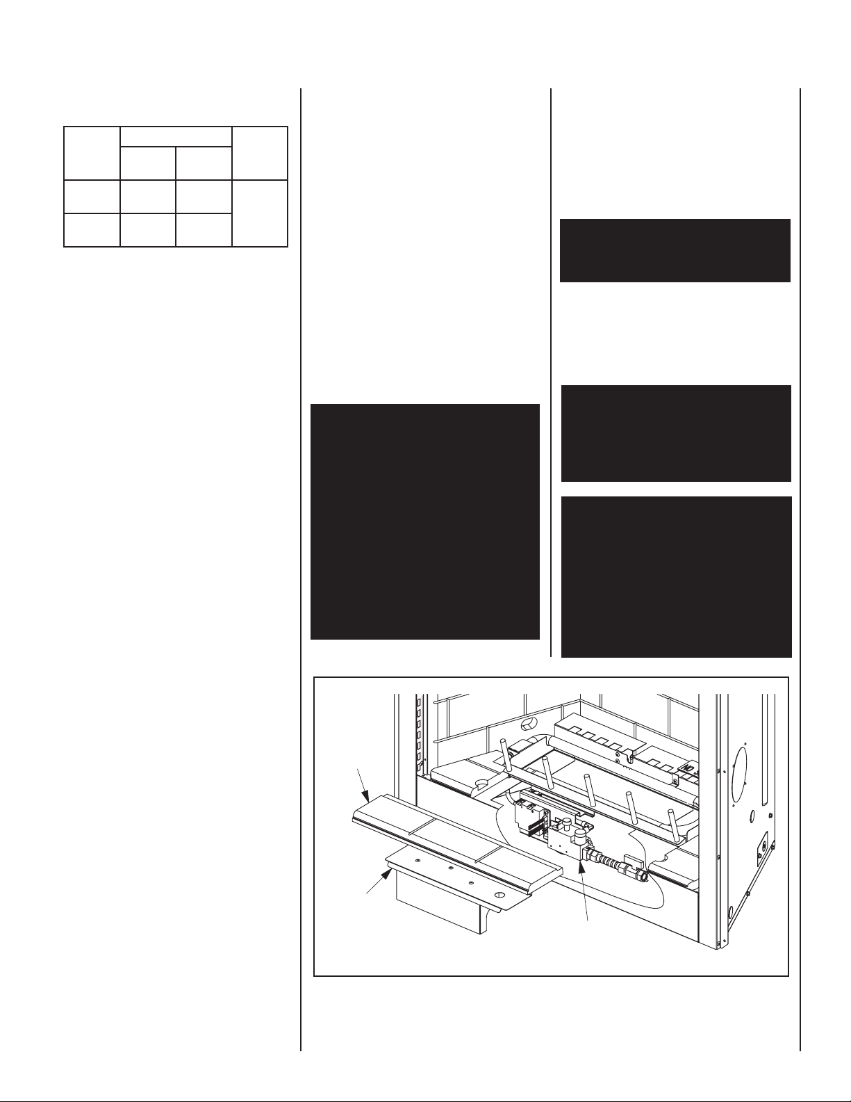
Access
Cover
Control
V
alve
Refractor
y
Cover
the elevations indicated.
Table 1
Units are tested and approved for elevations
of 0 to 4500 feet (0 to 1372 meters).
For elevations above 4500 feet (1372 meters),
install the unit according to the regulations of
the local authorities having jurisdiction and,
in the USA, the latest edition of the National
Fuel Gas Code (ANSI Z223.1) or, in Canada,
the latest edition of the CAN1-B149.1 and
.2 codes.
Maximum manifold pressure is 3.5 in. w.c. (0.87
kPa) for natural gas and 10 in. w.c. (2.49 kPa)
for LP/Propane gas.
The minimum manifold pressure on low is 2.2
in. w.c. (0.55 kPa) for natural gas and 6.3 in.
w.c. (1.57 kPa) for LP/Propane gas.
Do not use these appliances if any part has
been under water. Immediately call a qualified,
professional service technician to inspect the
appliance and to replace any parts of the control
system and any gas control which have been
under water.
Minimum inlet gas pressure to these appliances is 5.0 inches water column (1.24 kPa)
for natural gas and 11 inches water column
(2.74 kPa) for propane for the purpose of input
adjustment.
Maximum inlet gas supply pressure to these
appliances is 10.5 inches water column (2.61
kPa) for natural gas and 13.0 inches water
column (3.23 kPa) for propane.
The appliance and its individual shut-off valve
must be disconnected from the gas supply
piping system during any pressure testing of
that system at pressures in excess of 1/2 psig
(3.5 kPa).
Any safety guard or screen removed for servicing the appliance must be replaced prior to
operating the appliance.
WARNING: FAILURE TO COMPLY WITH
THE INSTALLATION AND OPERATING
INSTRUCTIONS PROVIDED IN THIS
DOCUMENT WILL RESULT IN AN IMPROPERLY INSTALLED AND OPERATING
APPLIANCE, VOIDING ITS WARRANTY.
ANY CHANGE TO THIS APPLIANCE
AND/OR ITS OPERATING CONTROLS
IS DANGEROUS. IMPROPER INSTALLATION OR USE OF THIS APPLIANCE
CAN CAUSE SERIOUS INJURY OR DEATH
FROM FIRE, BURNS, EXPLOSION OR
CARBON MONOXIDE POISONING.
Carbon Monoxide Poisoning: Early signs
of carbon monoxide poisoning are similar
to the flu with headaches, dizziness and/or
nausea. If you have these signs, obtain
fresh air immediately. Turn off the gas supply to the appliance and have it serviced by
a qualified professional, as it may not be
operating correctly.
WARNING: DO NOT PLACE CLOTHING
OR OTHER FLAMMABLE MATERIALS
ON OR NEAR THIS APPLIANCE.
The appliance must be isolated from the gas supply
piping system (by closing its individual manual
shut-off valve) during any pressure testing of the
gas supply piping system at test pressures equal
to or less than 1/2 psig (3.5 kPa).
AVERTISSEMENT: SURVEILLER LES
ENFANTS. GARDER LES VÊTEMENTS,
LES MEUBLES, L'ESSENCE OU AUTRES
LIQUIDES À VAPEUR INFLAMMABLES
LOIN DE L'APPAREIL.
WARNING: CHILDREN AND ADULTS
SHOULD BE ALERTED TO THE HAZARDS
OF HIGH SURFACE TEMPERATURES.
USE CAUTION AROUND THE APPLIANCE TO AVOID BURNS OR CLOTHING
IGNITION. YOUNG CHILDREN SHOULD
BE CAREFULLY SUPERVISED WHEN
THEY ARE IN THE SAME ROOM AS THE
APPLIANCE.
Ne pas se servir de cet appareil s'il a été plongé
dans l'eau, complètement ou en partie. Appeler
un technicien qualifié pour inspecter l'appareil
et remplacer toute partie du système de contrôle et toute commande qui ont été plongés
dans l'leau.
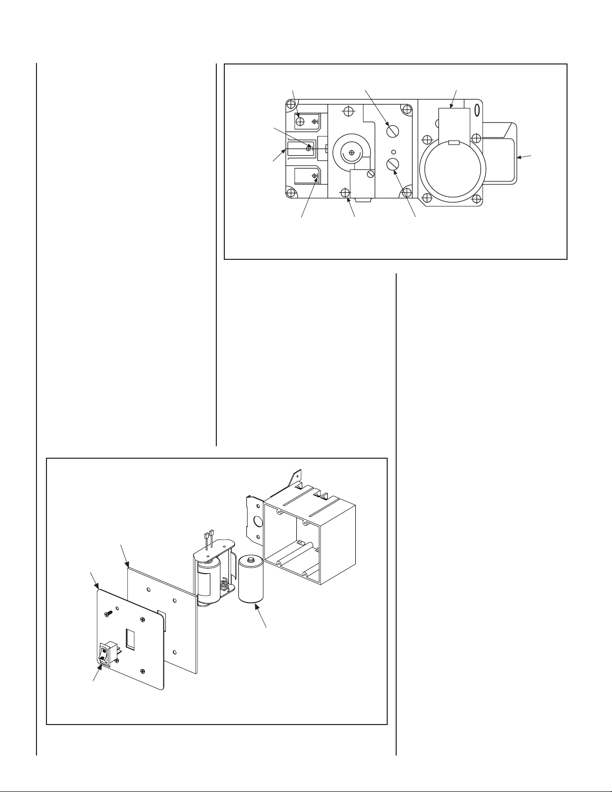
Test gage connections are provided on the front
of the electronic gas control valve (identified OUT
for the manifold side and IN for inlet pressure.
A 1/8" NPT test gage connection is provided on
the electronic gas control valve adjacent to the
outlet to the main burner.
Figure 1
NOTE: DIAGRAMS & ILLUSTRATIONS NOT TO SCALE.
3
Page 4
OPERATION AND CARE OF YOUR
Switch
Cover
Weather Seal
Orient Batteries Vertically
To Fit Within Box
Pilot Stage
Terminal
Pressure-Tap
(Inlet)
Pilot Gas
Outlet
Supply
Gas
Inlet
Pressure-Tap
(Manifold)
Burner Stage
Terminal
Ground
(TP)
PILOT
OUT
VENT
LO
TH
TP
TH
TP
HI
IN
IN
Gas Outlet
To Burner
Regulator
Mounting Screw
APPLIANCE
Appliance operation may be controlled by a
remotely located wall switch.
Gas Controls/Control Compartment Access
The gas controls can be found beneath the bottom refractory. Remove the bottom refractory
by lifting it up. Remove the access cover (refer
to Figure 1 ).
All Models -
To light these appliances refer to the detailed
lighting instructions found in both English and
French on pages 14 and 15 of these instructions
respectively. The appliance lighting instruc-
tions may also be found on the pull out lighting
instruction labels attached to the gas control
valve. See Figure 1 for its location.
Variable Flame Height Adjustment
1. All appliances are equipped with a variable
gas control valve. Flame height for these models
may be adjusted through a range between fixed
low and high settings, alternately, while the
appliance is in operation.
Adjust the flame height as desired after lighting
the appliance by rotating the variable adjustment
control knob located on the front of the valve
(see Figure 2).
Figure 2
2. When lit for the first time, this appliance will
emit a slight odor for an hour or two. This is due
to the “burn-in” of internal paints and lubricants
used in the manufacturing process.
3. Keep lower control compartment clean by
vacuuming or brushing at least twice a year.
More frequent cleaning may be required due to
excessive lint from carpeting, bedding materials,
etc. It is important that control compartments,
burners and circulating air passageways of the
appliance be kept clean.
4. Always keep the appliance area clear and
free from combustible materials, gasoline and
other flammable liquids.
Dexen Electronic Gas Valve
Maintenance
The appliance should be thoroughly inspected
before initial use and at least annually by a
qualified service technician. However, more
frequent periodic inspections and cleanings
should be performed by the homeowner.
Homeowner must contact a qualified service
technician at once if any abnormal condition
is observed.
Refer to the maintenance schedule for maintenance tasks, procedures, periodicity and
by whom they should be performed. Always
verify proper operation of the appliance after
servicing.
4
Figure 3 Battery Replacement
NOTE: DIAGRAMS & ILLUSTRATIONS NOT TO SCALE.
IMPORTANT: TURN OFF GAS AND ANY
ELECTRICAL POWER BEFORE SERVICING
THE APPLIANCE.
Battery Replacement
The intermittent ignition system operates on 3
volts provided by two (2) "D" cell batteries. The
batteries are located in a pack installed within
the J-Box, behind the stainless ON/OFF switch
panel. Refer to Figure 3.
Note: All batteries loose voltage when frozen
or left for prolonged periods. It may be wise
to remove batteries during extended periods
of disuse.
Page 5
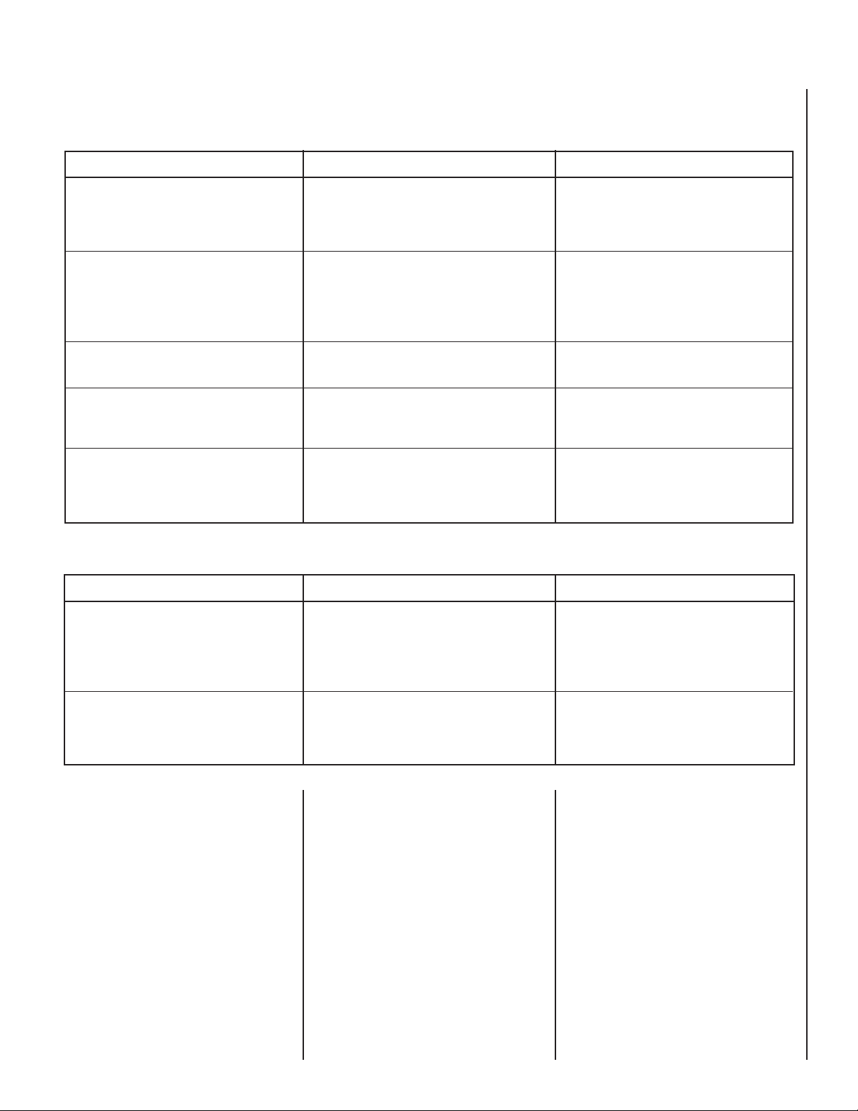
Maintenance Schedule
Annually (Before the onset of the Burning Season)
Maintenance Task Accomplishing Person Procedure
Inspecting/Cleaning Burner, Logs
and Controls
Inspecting/Cleaning Pilot and Burner
Appliance Checkout
Replacing Rock Ember Materials
Replace Spent Batteries
Periodically (After the Burning Season)
Maintenance Task Accomplishing Person Procedure
Qualified Service Technician
Qualified Service Technician
Qualified Service Technician
Homeowner/Qualified Services Technician
Homeowner
Inspect valve and ensure it is properly operating. Check piping for leaks. Vacuum
the control compartment, fireplace logs and
burner area.
Refer to Figure 10 (Dexen) on page 8. Remove
any surface build-up on pilot and burner assembly. Wipe the pilot nozzles, ignitor/flame
rod and hood. Ensure the pilot flame engulfs
the flame sensor as shown.
Perform the appropriate appliance checkout
procedure detailed in this manual.
Remove old ember materials and vacuum
the rock placement area. Place new rock as
described in this document.
Locate and remove the four (4) screws retaining the stainless J-Box cover. Remove the
battery pack and replace the two (2) "D" cell
batteries.
Cleaning Firebox Interior
Replace Spent Batteries
Reset Limit Switch
Step 1. Remove bottom middle refractory
panel (#4) and valve cover assembly (#9) to
gain access to the limit switch (#25).
Step 2. Slide your left hand into the fireplace
and use your middle finger to feel for two
wires connected to the limit switch. Follow
up, in between the two wires is the reset button, located on the back of the limit switch.
Refer to Figure 4 and Figure 5 on page 6 for
more detail.
Homeowner
Homeowner
Note: Make sure you have new batteries and
all lava rock has filled the pan and that the logs
are set correctly.
Burner Adjustments
The following paragraphs address burner
adjustment concerns and procedures.
Carefully remove logs and decorative volcanic
stone. Vacuum out interior of the firebox.
Clean firebox walls and log grate. Replace
logs, Rockwool and volcanic stone as detailed
in this manual.
Locate and remove the four (4) screws retaining the stainless J-Box cover. Remove
the battery pack and replace the two (2) "D"
cell batteries.
Flame Appearance and Sooting
Proper flame appearance is a matter of taste.
Generally most people prefer the warm glow of
a yellow to orange flame. Appliances operated
with air shutter openings that are too large will
exhibit flames that are blue and transparent.
These weak, blue and transparent flames are
termed anemic. If the air shutter opening is too
small excessive sooting may develop.
NOTE: DIAGRAMS & ILLUSTRATIONS NOT TO SCALE.
5
Page 6

Sooting is indicated by black puffs developing
Shutter
Opening
1/16” For
Natural Gas
1/2” Open
For LP
at the tips of very long orange flames. Sooting
results in black deposits forming on the logs,
appliance inside surfaces and on exterior surfaces adjacent to the face opening.
Sooting is caused by incomplete combustion in
the flames and a lack of combustion air entering
the air shutter opening. To achieve a warm yellow
to orange flame with an orange body that does
not soot, the shutter opening must be adjusted
between these two extremes.
Limit Switch Detail
Limit Switch Location
These appliances should not smoke. Small
amounts of soot will accumulate over time
and should be expected. This soot adds to the
realism of the firebox interior. The logs can be
cleaned, when cool, with a soft brush and small
amounts of water.
If the logs are properly positioned and excessive sooting conditions exist, the air shutter
opening on the main burner tube should be
adjusted. Keep in mind that this is an outdoor
appliance. Wind and air currents cannot be
strictly controlled.
If the flame acts too erratically, we recommend
that the screens be closed.
WARNING: AIR SHUTTER ADJUSTMENT
SHOULD ONLY BE PERFORMED BY A
QUALIFIED PROFESSIONAL SERVICE
TECHNICIAN.
Burner Adjustment
CAUTION: THE SHUTTER AND NEARBY APPLIANCE SURFACES ARE HOT. EXERCISE CAUTION TO AVOID INJURY WHILE ADJUSTING
FLAME APPEARANCE.
Figure 4
Slide Left Hand
Underneath
Limit Switch
Figure 5
Limit
Switch
Use Middle Finger To Press
Reset Button On Underside
Of Limit Switch
To adjust the flame, turn the shutter (located
in the left side of the burner pan) up or down
to increase or reduce the air shutter opening,
respectively. Position the air shutter to the
factory setting, as shown in Figure 6.
Allow the burner to operate for at least 15
minutes. Observe the flame continuously. If it
appears weak or sooty as previously described,
adjust the air shutter by rotating the shuter until
the flame appearance is as desired.
When satisfied that the appliance operates
properly, proceed to finish the installation. Leave
the control knob in “ON” position and turn the
remote switch “OFF.” Reinstall the access and
refractory cover.
6
Figure 6
NOTE: DIAGRAMS & ILLUSTRATIONS NOT TO SCALE.
Page 7

Log Placement
WARNING: LOGS GET VERY HOT AND
WILL REMAIN HOT UP TO ONE HOUR
AFTER GAS SUPPLY IS TURNED OFF.
HANDLE ONLY WHEN LOGS ARE COOL.
TURN OFF ALL ELECTRICITY TO THE APPLIANCE BEFORE YOU INSTALL GRATE
AND LOGS.
WARNING: THIS APPLIANCE IS NOT
MEANT TO BURN WOOD. ANY ATTEMPT
TO DO SO COULD CAUSE IRREPARABLE
DAMAGE TO YOUR APPLIANCE AND
PROVE HAZARDOUS TO YOUR SAFETY.
WARNING: THE SIZE AND POSITION OF
THE LOG SET WAS ENGINEERED TO GIVE
YOUR APPLIANCE A SAFE, RELIABLE
AND ATTRACTIVE FLAME PATTERN.
ANY ATTEMPT TO USE A DIFFERENT
LOG SET IN THE FIREPLACE WILL VOID
THE WARRANTY AND WILL RESULT IN
INCOMPLETE COMBUSTION, SOOTING,
AND POOR FLAME QUALITY.
Rear Log
Figure 7
Base Log
CAUTION: NEVER OPERATE THE FIREPLACE
WITHOUT THE LAVA ROCKS IN THE BURNER
PAN. PROLONGED USE WITHOUT THE
ROCK IN PLACE WILL OVERHEAT THE PAN
AND CAUSE THE FIREPLACE TO SHUTOFF
AUTOMATICALLY.
After verifying that the fireplace operates
properly, replace the cover and set the bottom
refractory components in place.
Use two (2) bags of lava rock to fill the bottom
of the burner tray to completely cover the burner
tube. Level the rock evenly.
Place the rear log approximately centered as
shown in Figure 7.
Place the base log approximately as shown
in Figure 8.
The remaining logs can be placed across the
rear and base log approximately as shown in
Figure 9. The exact position of these logs is
not critical. Due to the nature of an outdoor
environment, the flame will never be strictly
controlled. You may need to reposition the logs
to get the effect you find most desirable.
Figure 8
Top Left Log
Top Center Log
Top Right Log
WARNING: LAVA ROCK WITHIN THE
BURNER CAN "POP" FOR THE FIRST FEW
FIRES. WIND BORNE DEBRIS MAY ALSO
ENTER THE FIREPLACE INEXPEDIENTLY.
IN HIGH WIND CONDITIONS, OPERATE
THE APPLIANCE WITH THE SCREENS OR
DOORS CLOSED.
Figure 9
NOTE: DIAGRAMS & ILLUSTRATIONS NOT TO SCALE.
7
Page 8

Electronic Appliance Checkout
Decorative Bi-Fold Doors
This attractive Bi-Fold door is easy to install
and enhances the appearance of the appliance.
Decorative Bi-Fold Doors
Cat. No. Model
Description
H4645 36LBFOD-BS 36” Otdr B-F Door, Brshd SS
H4646
42LBFOD-BS
42” Otdr B-F Door, Brshd SS
Outdoor Weather Cover
This attractive Outdoor Weather Cover is easy
to install and protects the firebox interior from
adverse weather.
Outdoor Weather Cover
Cat. No. Model
Description
H4647 36-EODC 36” SS Otdr Weather Cover
H4648
42-EODC
42” SS Otdr Weather Cover
Hood Kit
This attractive Hood Kit is easy to install and
enhances the appearance of the appliance.
Outdoor Hood Kit
Cat. No. Model
Description
H4818 ODGHK36 36” Hood Kit Outdoor Gas
H4819
42” Hood Kit Outdoor Gas
ODGHK42
Decorative Volcanic Stone
The decorative volcanic stone, Model FDVS,
can be used to enhance the look of your appliance. Order model FDVS for replacement
of stone when needed. Spread the decorative
volcanic stone evenly around the bottom of
the firebox.
Decorative Volcanic Stone
Cat. No. Model No. Description
80L42 FDVS Bag of Volcanic Stone
ELECTRONIC
Pilot
Hood
Sensor
Ignitor
To light the burner, refer to the lighting instructions on page 10. Ensure the ignitor lights the
pilot. The pilot flame should engulf the flame
sensor as shown in Figure 10.
With proper care and maintenance, your appliance will provide many years of enjoyment. If
you should experience any problem, first refer
to the trouble shooting guide in this manual.
If problem persists, contact your Lennox
distributor.
ACCESSORY COMPONENTS
Figure 10
8
NOTE: DIAGRAMS & ILLUSTRATIONS NOT TO SCALE.
Page 9

WIRING DIAGRAMS
INTERMITTENT ELECTRONIC WIRING DIAGRAM
BROWN
BROWN
BLACK
BATTERY
WALL SWITCH BOX
BLACK (SENSOR)
BLACK (IGNITOR)
SPARK TO PILOT IGNITOR
IGNITOR MODULE
3V
RED
PILOT
IN
OUT
VENT
LO
HI
TH
TP
TH
TP
IN
ORANGE (THTP)
BLACK (TP)
GREEN (TH)
LIMIT
SWITCH
UMBILICAL CORD (9 Feet)
Wiring diagrams are provided here for reference purposes only. This information is also provided on schematics attached directly to the appliance
on a pullout panel located within the control compartment.
CAUTION: LABEL ALL WIRES PRIOR TO DISCONNECTION WHEN SERVICING CONTROLS. WIRING ERRORS CAN CAUSE IMPROPER AND DANGEROUS APPLIANCE OPERATION.
WARRANTY
Your gas appliance is covered by a limited twenty
year warranty. You will find a copy of the warranty accompanying this manual. Please read
the warranty to be familiar with its coverage.
Retain this manual. File it with your other documents for future reference.
PRODUCT REFERENCE INFORMATION
We recommend that you record the following important information about your fireplace. Please
contact your Lennox dealer for any questions or concerns. For the number of your nearest Lennox
dealer, please call 1-800-9-LENNOX.
Your Fireplace's Model Number ________________________________________
Your Fireplace's Serial Number ________________________________________
The Date On Which Your Fireplace Was Installed ___________________________
The Type of Gas Your Fireplace Uses ____________________________________
Your Dealer's Name ________________________________________________
REPLACEMENT PARTS
A complete parts list is found at the end of
this manual. Use only parts supplied from the
manufacturer.
Normally, all parts should be ordered through
your Lennox distributor or dealer. Parts will be
shipped at prevailing prices at time of order.
NOTE: DIAGRAMS & ILLUSTRATIONS NOT TO SCALE.
When ordering repair parts, always give the
following information:
1. The model number of the appliance.
2. The serial number of the appliance.
3. The part number.
4. The description of the part.
5. The quantity required.
6. The installation date of the appliance.
If you encounter any problems or have any questions concerning the installation or application
of this system, please contact your distributor,
or Lennox directly:
LENNOX HEARTH PRODUCTS
1110 West Taft Avenue
Orange, CA 92865
9
Page 10

LIGHTING INSTRUCTIONS — ELECTRONIC
PILOT
OUT
VENT
LO
TH
TP
TH
TP
HI
IN
IN
FOR YOUR SAFETY READ BEFORE LIGHTING
WARNING: IF YOU DO NOT FOLLOW THESE INSTRUCTIONS EXACTLY, A FIRE OR EXPLOSION MAY
RESULT CAUSING PROPERTY DAMAGE, PERSONAL INJURY OR LOSS OF LIFE.
A. When lighting the appliance, follow these instructions
exactly.
B. BEFORE OPERATING smell all around the appliance area
for gas. Be sure to smell next to the floor because some
gas is heavier than air and will settle on the floor.
WHAT TO DO IF YOU SMELL GAS
• Extinguish any open flame.
• Open windows.
• Do not light any appliance.
• Do not touch any electrical switches.
• Do not use any phone in your building.
LIGHTING INSTRUCTIONS
1. STOP! Read the safety information above on this page.
2. Turn remote wall switch to “OFF".
3. This appliance is equipped with an ignition device which
automatically lights the pilot. Do not try to light the pilot
by hand.
4. Allow sufficient length of time (minimum 5 minutes) for
any gas in the combustion chamber to escape. If you
still smell gas, STOP! Follow “B” in the safety information above on this page. If you do not smell gas, go to the
next step.
• Immediately call your gas supplier from a neighbor’s
phone.
• If your gas supplier cannot be reached, call the fire
department.
C. Use only your hand to turn the gas control lever. Never
use tools. If the lever will not turn by hand, do not try
to repair it, call a qualified service technician. Force or
attempted repair may result in a fire or an explosion.
D. Do not use this appliance if any part has been under
water. Immediately call a qualified service technician
to inspect the appliance and to replace any part of the
control system and any gas control which has been under
water.
5. Push the wall mounted "ON/OFF" switch back to the "ON"
position.
- If the burner does not light, replace steps 2 through 5.
- If the burner will not light or stay lit after several tries,
turn the wall mounted "ON/OFF" switch to the "OFF" position and call your service technician or gas supplier.
Note: Sufficient time must be allowed for air to escape
from lines if the unit is being lit for the first time.
6. Turn HI-LO burner control knob to desired setting and
close control door.
7. If the appliance will not operate, follow the instructions
"To Turn Off Gas To Appliance" and call your service technician or gas supplier.
TO SHUT OFF
1. Turn off all electrical power to the appliance (remote wall
switch).
TO TURN OFF GAS TO APPLIANCE
1. For complete shut-down, turn remote wall switch to “OFF".
2. Turn off all electrical power to the appliances and
remove the batteries if service e is to be performed or
for extended shutdown.
10
NOTE: DIAGRAMS & ILLUSTRATIONS NOT TO SCALE.
Page 11

INSTRUCTIONS D’ALLUMAGE — ELECTRONIC
PILOT
OUT
VENT
LO
TH
TP
TH
TP
HI
IN
IN
POUR VOTRE SÉCURITÉ, LISEZ CES INSTRUCTIONS AVANT L’ALLUMAGE
AVERTISSEMENT: SI VOUS NE SUIVEZ PAS CES INSTRUCTIONS À LA LETTRE, IL POURRAIT S’EN SUIVRE UN INCENDIE OU UNE
EXPLOSION CAUSANT DES DOMMAGES MATÉRIELS, DES BLESSURES CORPORELLES OU MÊME DES PERTES DE VIE.
A. Lorsque vous allumez l’appareil, suivez exactement ces instruc-
tions.
B. AVANT L’ALLUMAGE: Assurez-vous que vous ne détectez
aucune odeur de gaz autour de l’apareil ainsi que près du sol;
certains gaz, étant plus lourds que l’air, descendent au niveau
du sol.
VOICI CE QUE VOUS DEVEZ FAIRE SI VOUS DÉCELEZ UNE
ODEUR DE GAZ
• Éteignez toute flamme visible.
• Ouvrez les fenêtres.
• N’allumez aucun appareil.
• Ne touchez à aucun commutateur électrique.
• Ne vous servez d’aucun téléphone dans votre édifice.
INSTRUCTIONS D’ALLUMAGE
1. ARRÊTEZ ! Lisez les consignes de sécurité au verso de cette
plaque.
2. Tournez l’interrupteur mural à distance à la position arrêt (off) ou
placez le thermostat à la plus basse température possible, si requis.
3. Cet appareil est équipé d’un dispositif d’allumage qui allume
automatiquement le brûleur. N’essayez pas d’allumer le brûleur
à la main.
4. Attendez au moins 5 minutes pour que le gaz qui se trouve
dans la chambre de combustion puisse s'échapper. Si vous sentez
encore une odeur de gaz, ARRÊTEZ ! Référez-vous à la section B
des consignes de sécurité de l'autre côté de cette plaque. Si vous
ne sentez pas d'odeur de gaz, allez à la prochaine étape.
• Appelez immédiatement votre compagnie de gaz en utilisant
le téléphone du voisin.
• S’il vous est impossible de contacter votre compagnie de
gaz, appelez le service des incendies.
C. N’utilisez que votre main pour manipuler linterrupteur
“ON/OFF” de la valve à gaz. N’utilisez jamais d’outils. Si
l’interrupteur ne bouge pas manuellement, n’essayez pas de le
réparer. Communiquez immèdiatement avec un technicien de
service qualifié. Toute tentative pour forcer l’interrupteur ou le
réparer, risquerait de provoquer un incendie ou une explosion.
D. Ne vous servez pas de cet appareil si l’un de ses éléments a
été immergé dans l’eau. Appelez immédiatement un technicien
compétent pour faire inspecter l’appareil et remplacer toute
pièce du système de réglage ou commande du gaz qui a été
sous l’eau.
5. Poussez le commutateur de L’unité à la position marche (on) le
commutateur de l’unité peut aussi être complémenté d’un interrupteur mural.
- si le brûleur ne s’allume pas, répétez les étapes 2 à 5.
- si le brûleur ne s’allume pas ou ne reste pas allumé après plusieurs
essais, tournez le commutateur de l’unité à la position arrêt (off) et
appelez votre fournisseur de gaz ou votre technicien de service.
Note : Si vous allumez l'unité pour la première fois, vous devrez attendre un certain temps afin que l'air puisse s'échapper des conduits.
6. Tournez le bouton de commande du brûleur HI-LO à la position
désirée et fermez la porte. Ajustez le thermostat à la temperature
désirée, si requis.
7. Si l'appareil ne fonctionne pas, suivez les instructions Comment
fermer le gaz qui alimente l'appareil et contactez votre fournisseur
de gaz ou technicien de service.
POUR ÉTEINDRE L'APPAREIL
1. Coupez le courant électrique qui alimente l'appareil (interrupteur mu-
ral) ou placez le thermostat à la plus basse température, si requis.
POUR FERMER LE GAZ QUI ALIMENTE L’APPAREIL
1. Pour une fermeture complète, tournez l'interrupteur mural à
la position arrêt (OFF) ou placez le thermostat à la plus basse
température.
NOTE: DIAGRAMS & ILLUSTRATIONS NOT TO SCALE.
2. Coupez l'alimentation électrique du foyer et retirez les batteries
de sécurité si vous prévoyez faire le service de l'appareil ou si vous
ne l'utilisez pas à long terme.
11
Page 12

TROUBLESHOOTING THE ELECTRONIC IGNITION SYSTEM
Note: Before troubleshooting, be sure that the appliance main line gas shut-off valve, the gas control valve and the wall
switch are in the “ON” position.
Important: Valve system troubleshooting should only be accomplished by a qualified service technician.
SYMPTOM POSSIBLE CAUSES CORRECTIVE ACTION
1. Nothing happens when
ON/OFF switch is turned
on (pilot does not spark).
2. The main burner does
not light and the igniter
is sparking.
3. The main burner come
"ON" but then go "OFF".
A. Dead batteries.
B. Low voltage/or bad lead
wires.
C. Damaged igniter wire.
D. Damaged pilot assembly.
A. No fuel supply.
B. Loose sensor wire.
C. Lose wires to valve.
D. Loose wires to ignition
module.
E. Air in the gas line.
F. Low voltage.
A. Gas supply is turned
"OFF".
B. Loose wire connection on
valve or ignition module.
Replace batteries (Refer to page 4).
Check voltage on the batteries. The value should be around 2.7 to 3.2 VAC.
Confirm that wire connections are secure.
Check for visible cracked casing, cuts, etc.
Check pilot assembly for visibly broken spark electrode, etc.
Ensure that the gas supply is turned on.
Ensure sensor wire connection is secure.
Ensure black, green and orange wires connection is secure to valve.
Ensure black sensor wire (S) and black igniter wire (I) is secure to ignition
module.
Purge gas line of air.
Test voltage at the batteries. It should be around 2.7 to 3.2 VAC.
Turned gas supply to "ON".
Check wire connection.
12
4. Log soot.
5. The main burner shuts
off but the pilot remains
lit.
C. Flame does not engulf
flame sensor.
A. Flame impingement on
the log.
B. Improper air shutter
opening.
A. Lose wire to valve or limit
switch has activated.
NOTE: DIAGRAMS & ILLUSTRATIONS NOT TO SCALE.
Check location of sensor.
Check for proper log placement.
Check for proper air shutter openings.
Allow the unit to cool to below 220° F and then reset the limit switch. Refer
to Reset Limit Switch on page 5. Check the burner pan for the proper application of lava rock.
Page 13

NOTES:
NOTE: DIAGRAMS & ILLUSTRATIONS NOT TO SCALE.
13
Page 14

REPLACEMENT PARTS LIST
.oN NOITPIRCSED
GDO"63 GDO"24
.oNtraP .ytQ .oNtraP .ytQ
ylbmessAecalperiFsaG – – – –
.1 ediSHL,yrotcarfeR 7183H 1 7183H 1
.H1 enobgnirreHHL,yrotcarfeR 0383H 1 0383H 1
.2 ediSHR,yrotcarfeR 6183H 1 6183H 1
.H2 enobgnirreHHR,yrotcarfeR 9283H 1 9283H 1
.3 raeR,yrotcarfeR 9183H 1 4283H 1
.H3 enobgnirreHraeR,yrotcarfeR 3283H 1 1383H 1
.4 elddiM,mottoB,yrotcarfeR 2594H 1 2594H 1
.5 )HL(ediS,mottoB,yrotcarfeR 8494H 1 9494H 1
.6 )HR(ediS,mottoB,yrotcarfeR 0594H 1 1594H 1
.7 yrotcarfeR,pilC 8993H 4 8993H 4
.A8 )saGlarutaN(ylbmessAniarTsaG 1494H 1 1494H 1
.B8 )saGenaporP(ylbmessAniarTsaG 2494H 1 2494H 1
.9 ylbmessArevoCevlaV 7494H 1 7494H 1
.01 emarFpoT 3394H 1 4394H 1
.11 emarFmottoB 5394H 1 6394H 1
.21 )HL(tsoPrenroC 7394H 1 7394H 1
.31 )HR(tsoPrenroC 8394H 1 8394H 1
.41 tekcarBffO-dnatS 2183H 4 2183H 4
.51 )sseccAsaG(etalPrevoC 5594H 1 5594H 1
.61 teSgoL 2394H 1 2394H 1
.71 neercS 6294H 2 7294H 2
.81 doRneercS 9394H 2 0494H 2
.91 ylbmessArenruB,ebuT 0394H 1 0394H 1
.02 tekcarBrenruB 2984H 2 2984H 2
.12 troppuSebuTrenruB 3594H 2 3594H 2
.22 rotcennoCxelF 33K34 2 33K34 2
.32 )derutciPtoN(enotScinacloV 24L08 3 24L08 3
.42 )derutciPtoN(tiKlacirtcelE 4594H 1 4594H 1
.52 hctiwStimiL 22M31 1 22M31 1
14
NOTE: DIAGRAMS & ILLUSTRATIONS NOT TO SCALE.
Page 15

REPLACEMENT PARTS
13
12
4
17
18
3
14
5
6
11
3H
16
15
1
2
1H
2H
7
(RIGHT SIDE)
(RIGHT SIDE)
8A
9
10
8B
21
19
20
22
25
NOTE: DIAGRAMS & ILLUSTRATIONS NOT TO SCALE.
15
Page 16

Lennox Hearth Products reserves the right to make changes at any time, without notice, in
design, materials, specifications, prices and also to discontinue colors, styles and products.
Consult your local distributor for fireplace code information.
Printed in U.S.A. © 2006 by Lennox Hearth Products
P/N 875,032M REV. D 04/2009
16
NOTE: DIAGRAMS & ILLUSTRATIONS NOT TO SCALE.
1110 West Taft Avenue • Orange, CA 92865
 Loading...