

Page 1
2000 Lennox Industries Inc.
Dallas, Texas
504,172M
04/2000
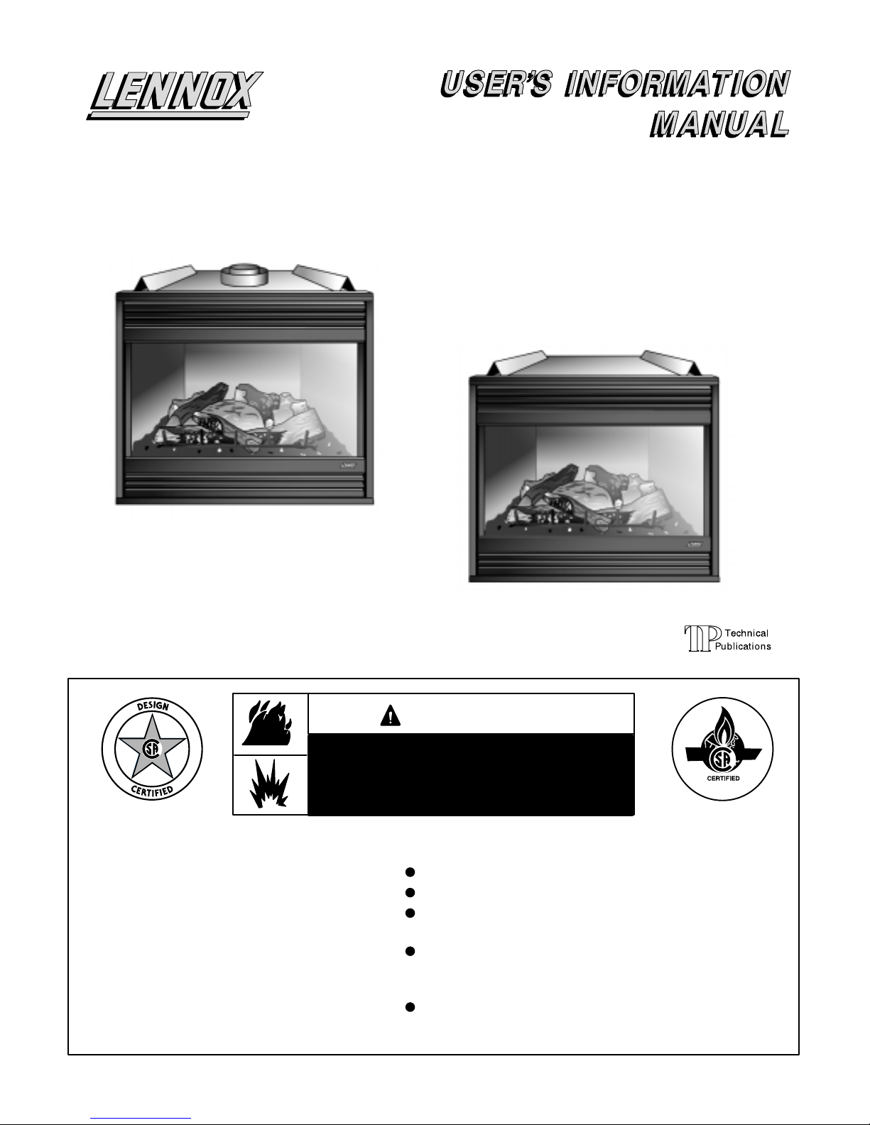
DT4540–2 LOUVERED FACE
TOP VENT MODEL SHOWN
DT–2 & DR–2
MERIT
VENTED GAS FIREPLACE HEATER
DIRECT VENT MODELS
SERIES
RETAIN THESE INSTRUCTIONS
FOR FUTURE REFERENCE
If the information in this manual is not
followed exactly, a fire or explosion
may result causing property damage,
personal injury or loss of life.
Do not store or use gasoline or other
flammable vapors and liquids in the
vicinity of this or any other appliance.
Installation and service must be performed by a qualified installer, service agency or the gas supplier.
DR4540–2 LOUVERED FACE
REAR VENT MODEL SHOWN
Litho USA
WARNING
WHAT TO DO IF YOU SMELL GAS:
Do not try to light any appliance.
Extinguish any open flames.
Do not touch any electrical switch; do not
use any phone in your building.
Immediately call your gas supplier from a
neighbor’s phone. Follow the gas supplier’s
instructions.
If you cannot reach your gas supplier, call
the fire department.
Page 1
Page 2
WARNING
Product contains fiberglass wool.
Disturbing the insulation in this product during
installation, maintenance, or repair will expose you
to fiberglass wool. Breathing this may cause lung
cancer. (Fiberglass wool is known to the State of
California to cause cancer.)
Fiberglass wool may also cause respiratory, skin,
and eye irritation.
To reduce exposure to this substance or for further
information, consult material safety data sheets
available from address shown below, or contact
your supervisor.
Lennox Industries Inc.
P.O. Box 799900
Dallas, TX 75379-9900 USA
WARNING
If overheating occurs or if gas supply fails to shut
off, shut off the manual gas valve to the appliance
before shutting off electrical supply.
WARNING
Do not use this furnace if any part has been under
water. Immediately call a qualified service techni
cian to inspect the furnace and to replace any part
of the control system and any gas control which
has been under water.
CAUTION
Before attempting to perform any service or mainte
nance, turn the electrical power to unit OFF at dis
connect switch.
IMPORTANT
Any additions, changes, or conversions required in
order for the appliance to satisfactorily meet the application needs must be made by a Lennox service
technician using factory specified and approved
parts.
WARNING
Improper installation, adjustment, alteration, service or maintenance can cause property damage,
personal injury or loss of life. Installation and service must be performed by a qualified installer, service agency or the gas supplier.
Important Directions
This appliance is intended only for use as indi-
cated in this manual and in the installation
instructions. Under no circumstances should
this fireplace be used to burn wood, paper, or
other combustibles of any kind.
The appliance will emit an odor for the first 10 to
12 hours of operation. Make sure the room is
well-ventilated and the burner is set for high
flame operation (if applicable) during this period.
Surface temperatures on the appliance are very
high. Make sure that both children and adults are
aware of the danger of burns or clothing ignition.
Do not leave children unsupervised in the room
with the appliance.
Keep clothing, draperies and furniture well away
from the front of the appliance.
Do not leave damp or wet clothing or other flam-
mable material to dry on or near the appliance.
If for any reason the glass frame is removed, all
three securing screws must be replaced and
tightened securely before the unit is put back
into operation.
Do not use this appliance if any part has been un-
der water. Call a qualified service technician to
inspect the appliance and replace electrical com ponents.
The control access panel becomes hot during
unit operation, and must be opened with care.
Refer to figure 1.
Service, including cleaning inside fire box,
should be done by a qualified service technician.
The appliance should be inspected and cleaned
annually by a qualified service technician. Service should include a thorough inspection of the
pilot and burner flame. The vent termination
should also be inspected for any blockage.
Clean inside and outside glass surfaces, and any
other of the appliance’s outside surfaces, using a
mild detergent/water solution and a soft cloth. DO
NOT use abrasive cleansers which might scratch
these surfaces. DO NOT attempt to clean these
surfaces when the appliance is operating or they
are hot to the touch. Glass cleaner is available as
Lennox part number 19N74.
Service and cleaning of internal components
must be performed by a qualified service technician.
WARNING
Do not operate the appliance with glass removed,
cracked or broken in any way. Glass must be replaced by a qualified service technician.
Page 2
Page 3

Lighting Information and Operation
WARNING
If you do not follow these instructions exactly, a fire
or explosion may result causing property damage,
personal injury or loss of life.
BEFORE LIGHTING smell all around the appliance area
for gas. Be sure to smell next to the floor because some
gas is heavier than air and will settle on the floor.
WHAT TO DO IF YOU SMELL GAS
Do not try to light any appliance.
Do not touch any electric switch; do not use any
phone in your building.
Immediately call your gas supplier from a neighbor's
phone. Follow the gas supplier's instructions.
If you cannot reach your gas supplier, call the fire de
partment.
Use only your hand to turn the gas control knob(s). Never
use tools. If the knob will not turn by hand, do not try to repair
it, call a qualified service technician. Force or attempted repair may result in a fire or explosion.
PLACING UNIT INTO OPERATION
(Millivolt Valves with Piezo Ignitor)
Fireplaces which include a millivolt valve are equipped
with a pilot which must be lit by a Piezo ignitor (red ignitor
button). When lighting the pilot, follow these instructions
exactly.
GAS VALVE OPERATION – Millivolt Valve (Figure 2)
1 – STOP! Read the safety information at the beginning
of this section.
2 – Turn OFF the burner switch (if applicable), or set the
thermostat to the lowest setting (if applicable).
3 – Turn off all electrical power t o a ppliance (if applicable).
4 – Open the control access panel. See figure1.
5 – Push in gas control knob slightly and turn clockwise
to OFF.
NOTE – Knob cannot b e t urned f rom PILOT to OFF unless knob is pushed in slightly. Do not force.
TO OPEN THE CONTROL ACCESS PANEL
The control access panel becomes hot during
unit operation, and must be opened with care:
Insert the ti p o f a f inger o f e ach h and ( with t he b ack of the
hands toward the panel) into the cutout in the bottom of
the panel at the positions shown, and rotate the panel
down.
FIGURE 1
6 – Wait five (5) minutes to clear out any gas. Then, smell
for gas, including near the floor. If you smell gas, STOP!
Follow the safety instructions given in the column to the
left. If you do not smell gas, go to the next step.
7 – Press partially and turn gas valve knob counterclock-
wise to PILOT.
8 – Push control knob in until it stops and hold knob in this
position. IMMEDIATELY light the pilot by pushing the
red Piezo ignitor button. Continue to press control knob
for 25 seconds after the pilot is lit. Release knob. It
should pop back up. Pilot should remain lit. If pilot goes
out, repeat steps 5 through 8.
MILLIVOLT GAS VALVE
HI/LO FLAME
ADJUSTMENT KNOB
CONTROL
KNOB
GAS VALVE SHOWN IN PILOT POSITION
FIGURE 2
9 – Press partially and turn gas valve knob counterclock-
wise to ON.
10 –Restore electrical power to appliance (if applicable)
11 –Turn ON the burner switch (if applicable), or set the
thermostat to the desired setting (if applicable).
12 –Close the control access panel.
NOTE – If gas valve is turned to OFF from ON or PILOT
while appliance is in operation, gas valve will latch in OFF
position for 25 seconds.
Page 3
Page 4

13 – If the appliance will not operate, follow the instr uctions
“Turning Off Gas to U nit” and c all your service technician
or gas supplier.
NOTE - Do not be alarmed if you notice an odor during the
initial 10 to 12 hours of operation. This is caused by ex
posing the components to heat for the first time. The odor
will dissipate quickly if windows are opened to allow in
creased air circulation.
TURNING OFF GAS TO UNIT
1 – Turn OFF the burner switch (if applicable), or set the
thermostat to the lowest setting (if applicable).
2 – Turn off all electrical power to appliance.
3 – Open the control access panel. See figure1.
4 – Push in gas control knob slightly and turn clock-
wise to OFF. Do not force.
5 – Close the control access panel.
PLACING UNIT INTO OPERATION
(Electronic Gas Valves)
Fireplaces equipped with an ignition device which will au tomatically light the burner. Do not try to light the burner
by hand. Follow these instructions exactly.
GAS VALVE OPERATION– Electronic Valve (Figure 3)
1 – STOP! Read the safety information at the beginning
of this section.
2 – Turn OFF the burner switch (if applicable), or set the
thermostat to the lowest setting (if applicable).
3 – Turn off all electrical power to the appliance.
4 – This appliance is equipped with an ignition device
which automatically lights the burner. Do not try to
light the burner by hand.
5 – Wait five (5) minutes to clear out any gas. Then, smell
for gas, including near the floor. If you smell gas, STOP!
Follow the safety instructions given in the left column on
the previous page, entitled: WHAT TO DO IF YOU
SMELL GAS." If you do not smell gas, go to the next
step.
ELECTRONIC GAS VALVE
HI/LO FLAME
ADJUSTMENT
KNOB
FIGURE 3
6 – Restore electrical power to the appliance.
7 – Turn ON the burner switch (if applicable), or set the
thermostat to the desired setting (if applicable).
8 – If the appliance will n ot o perate, f ollow t he i nstructions
to turn off gas to unit and call a service technician or
gas supplier.
NOTE - Do not be alarmed if you notice an odor during the
initial 10 to 12 hours of operation. This is caused by ex
posing the components to heat for the first time. The odor
will dissipate quickly if windows are opened to allow in
creased air circulation.
TURNING OFF GAS TO UNIT
1 – Turn OFF the burner switch (if applicable), or set the
thermostat to the lowest setting (if applicable).
2 – Turn off all electrical power to appliance.
3 – Turn OFF g as supply at main manual shut-off valve l o-
cated near the fireplace.
Page 4
Page 5

PLACING FIREPLACE INTO OPERATION
1 – Turn ON the burner switch (if applicable), or set the
thermostat to the desired setting (if applicable).
Millivolt models only, and in applications without
optional appliance-mounted or optional wall-
mounted ON/OFF switch or optional thermostat
– Press gas valve knob partially and turn counter-
clockwise to ON.
2 –
Optional standard blower
immediately. Burner will ignite in approximately three
to five seconds.
Optional deluxe blower
when a comfortable minimum temperature has been
reached.
, if installed, will energize
, if installed, will self-energize
NOTE – Immediately a fter burner i gnites, condensate may
temporarily fog g lass. T his i s n ormal. Fog w ill c lear a s soon
as temperatures w ithin t he f ire box r ise. I f d roplets c ontinue
to form after 15 minutes of operation on a high-flame setting, contact a qualified service technician.
NOTE – During the initial operation of the appliance, a
white film my f orm o n t he i nside o f t he g lass. T his i s n ormal.
If this occurs, clean the glass after the first 5 hours of use.
Burner Flame Adjustment
The burner flame on this appliance may be adjusted at the
gas valve to obtain the desired heating output. Burner
flame color varies with the different log sets and burners
available. In most cases the flame will be blue at start-up
and turn yellow after 5 to 10 minutes of operation. The
burner flame should be inspected at the beginning of each
heating season and burner should be cleaned by a service technician, if necessary.
Blower Operation (Deluxe models)
The optional deluxe blower may be controlled by a rheostat (provided with the deluxe blower) field-mounted remotely or on the appliance panel. The blower speed selected should approximate the heat output adjustment at
the gas valve. A high blower speed matched with a low
heat output can lead to condensation.
Vent Termination Inspection
Annually (before the heating season) inspect the appliance vent termination for any obstructions. If any are
found, remove them.
Contact your Lennox dealer for a periodic inspection by a
qualified service technician.
Service Reminder
Call your Lennox service technician if unit is inoperative.
Before calling, always check the following to be sure service is required.
1 – Check ON/OFF appliance-mounted switch (if appli-
cable) or wall-mounted switch (if applicable) to make
sure it is in ON position.
2 – Check room thermostat, if applicable, for proper set-
ting.
3 – Is pilot lit?
4 – Is gas valve in ON position (millivolt units)?
5 – Is gas turned ON at meter?
6 – Is manual main shut-off valve open?
7 – Is electrical power turned ON to the appliance (if ap-
plicable)?
Contact your local independent Lennox dealer for re-
placement parts.
To ensure the safe operation of your Lennox gas ap-
pliance and to keep it in peak operating condition year after year, contact your independent Lennox dealer about a
planned service program.
Page 5
 Loading...