

Page 1

E
2001 LennoxIndustries Inc.
Dallas, Texas
INSTALLATION
INSTRUCTIONS
DT/DTH/DR/DRH
DR4035 FLUSH-FACED MODEL SHOWN
This appliance may be installed in an aftermarket
permanentlylocated,manufactured(mobile)home,
wherenotprohibited bylocalcodes.Thisappliance
is onlyfor use withthe type ofgas indicated onthe
rating plate. This appliance is not convertible for
use with othergases, unless a certifiedkit is used.
RETAIN THESE INSTRUCTIONS
FOR FUTURE REFERENCE
MERITt
DIRECT VENT
VENTED GAS FIREPLACE/
VENTED GAS FIREPLACE HEATER
850,010M
05/2001
Supersedes 504,023M 11/99
Series
Litho USA
Table of Contents
DT/DTH/DR/DRH Unit Dimensions 2..................
MerittSeries DT/DTH/DR/DRH 2....................
Shipping and Packing List 3..........................
Requirements 3....................................
General 3.........................................
Combustion Air 4...................................
Location Selection 4................................
Installation Clearances 5............................
Framing 6.........................................
Installation 6......................................
Venting 12.........................................
Gas Piping 21......................................
Unit Start-up 21....................................
Adjustments 23.....................................
Service 24.........................................
Wiring Diagram - Millivolt Gas Valves 24...............
Wiring Diagram - Electronic Gas Valves 25.............
Repair Parts List 25.................................
Venting Kits & Available Components 26...............
WH Report No. J20046561
FORYOURSAFETY
Do not store or use gasoline or other
flammable vapors and liquids in the
vicinity of this or any other appliance.
Installation and service must be
performed by a qualified installer,
service agency or the gas supplier.
WARNING
If the information in this manual is not
followed exactly, a fire or explosion
may result causing property damage,
personal injury or loss of life.
WHAT TO DO IF YOU SMELL GAS:
Do not try to light any appliance.
Extinguish any open flames.
Do not touch any electrical switch; do not
use any phone in your building.
Immediately call your gas supplier from a
neighbor’s phone. Follow the gas supplier’s
instructions.
If you cannot reach your gas supplier, call
the fire department.
Page 1
Page 2

DT/DTH/DR/DRH Unit Dimensions - inches (mm)
D
D
D
D
D
FRAMING
SPACERS
(Top and Sides
and Rear)
A
G
7 (178)
(Louvered Front Model Shown)
COMBUSTION AIR - 7-1/2 (190)
*CONCENTRIC FLUE
FLUE - 4-1/2 (114)
* DT/DTH - top flue only
DR/DRH - rear flue only
TOP VIEW
NOTE - Eyebrow
hood shown as positioned
in louvered front model.
ELECTRICAL
INLET
2-3/4x2 (70x51)
COVER PLATE with
KNOCKOUT)
C
GAS INLET
(Either Side
and bottom)
3 (76)
2 (51)
B
3 (76)
E
D
FRONT VIEW
Model No. A B C D E **F G
T/DR3025
T/DR3025
DTH/DRH3025
DT/DR3530
T/DR3530
DTH/DRH3530
DT/DR4035
T/DR4035
DTH/DRH4035
T/DR4540
in. 19-7/8 30-1/8 30-1/8 24-1/2 14
mm 505 765 765 616 356
in. 24-7/8 35-1/8 32-1/8 29-1/2 16
mm 632 892 816 749 406
in. 29-7/8 40-1/8 37-1/8 34-1/2 21
mm 759 1019 943 876 533
in. 34-7/8 45-1/8 37-1/8 39-1/2 21
mm 886 1146 943 1003 533
16
(406)
9-3/4
(248)
RIGHT SIDE VIEW
**DR/DRH -rear flue only
1/2 (13)
2 (51)
1-5/8
(42)
18-1/4
464
20-1/4
514
25-1/4
641
25-1/4
641
FIGURE 1
Meritt Series - DT/DTH/DR/DRH
MerittSeries fireplaces are sealed-combustion (direct
vent), heat-circulating gas appliances. The appliances
utilizea100 percentsafetyshut-offgas controlwitheither
a Piezo ignition system or an electronic ignition system.
Models equipped with either electronic ignition or the optionalforcedair fanassemblyrequire 120Velectricalconnection. Decorative trim kits, a brickaded firebox lining,
forced air fan assemblies, a wall thermostat (for usewith
vented gas fireplace heater models only), and hand-held
remote ON/OFF controls are available as options. Refer
to table 1 for model designations.
Thefireplacehas provisionsforside(s) orbottomentryfor
gas piping. This appliance must be vented to the outside
andmustnot be connectedtoa flueservicinganotherappliance.
The appliance must be installed using only approved Lennox
concentric venting components (4-1/2 in. / 7-1/2 in.).
Themillivolt gasvalveused innon-electronicignition units is self-powered and does not require
120V power wiring.
Do not attempt to alter or modify the construction of the
appliance or venting components. Any modification or alteration ofconstructionwillvoid the warranty,certification
and approval of these units.
In vented gas fireplace heater models, burner operation
can be controlled by: a unit- or wall-mounted ON / OFF
switch, or an approved thermostat.
In vented gas fireplace models, burner operation can be
controlled by: a unit- or wall-mounted ON / OFF switch.
On modelswiththeoptional manually-modulated gas valve,
flame appearance and heat output can be controlled at the
gas valve.
TABLE 1
Models Listed
to Vented Gas
Fireplace
Standard
DT/DR3025
DT/DR3530
DT/DR4035
DT/DR4540
*DRH/DTH models available with louver front only.
Models Listed to
Vented Gas
Fireplace Heater
Standard
DTH/DRH3025
DTH/DRH3530
DTH/DRH4035
Suffixes Used with
C - Louver front
F - Flush-Faced Front*
N-NaturalGas
P - Propane Gas (LP)
M - Millivolt System
E - Electronic system
F**
9-15/16
252
12-7/16
316
14-15/16
379
17-7/16
443
Both Models
Page 2
Page 3

Shipping and Packing List
Package 1 of 1 contains:
1 - Assembledventedfireplace /vented fireplaceheater
(includes log set, rock wool)
1 - Envelope containing installation instructions, user’s
manual,warranty,surveycard;and with theDT/DTH
models, also a vent restrictor
1 - Eyebrow
Check for shipping damage. The receiving party should contact last carrier immediately if any shipping damage is found.
All venting components are ordered and shipped separately.
Requirements
Lennox MerittSeries vented gasfireplaces/vented gas
fireplace heaters are Warnock Hersey certified to ANSI
Z21.88b-1999 inUSA(In Canada, CSA-2.33b-M99), and
CAN/CGA-2.17-M91 in both USA and Canada.
Installation of Lennox gas appliances must conform with local buildingcodes.Inthe absence of local codes, unitsmust
be installed according to the current National Fuel Gas
Code(ANSI-Z223.1)inthe United St ates.The National Fuel
Gas Code is available from:
American National Standards Institute, Inc.
11 West 42nd Street
New York, NY 10036
In Canada,installationmust conform with current National Standard of Canada CAN/CGA-B149.1 “Installation
Code for Natural Gas Burning Appliances and Equipment” and CAN/CGA-B149.2 “Installation Code for Propane Gas Burning Appliances and Equipment” and other
applicable local codes.
This appliance is Warnock Hersey certified for installation
clearances to combustible material as listed on appliance
rating plate and in table 2. Accessibility and service clearances must take precedence over fire protection clearances.
TABLE 2 - CLEARANCES TO COMBUSTIBLES
BACK 1/2 in. (13 mm); 0 in. (0 mm) spacers
SIDES 1/2 in. (13 mm); 0 in. (0 mm) spacers
TOP SPACERS 0 in.(0 mm)
FLOOR 0 in. (0 mm)
VENT 1 in. (25.4 mm)*
SERVICE CLEARANCES
FRONT 3 FeeT. (0.9 meters)
* 3 in. (75mm) above any horizontal vent component.
NOTE - For installation on combustible floors, appliance shall
not be installed directly on carpeting, tile, or other combustible material other than wood flooring.
Fireplace must be installed so thatelectrical components
(if applicable) are protected from water.
When120volt power isinstalled,appliance must beelectrically grounded in accordance withlocalcodes.Inaddition, in the United States, installation must conform with
the current National Electric Code, ANSI/NFPA No. 70.
The National Electric Code (ANSI/NFPANo. 70) is available from:
National Fire Protection Association
1BatteryMarchPark
Quincy, MA 02269
In Canada, all electrical wiring and grounding for the unit
must beaccordingtothe current regulations of the Canadian Electrical Code Part I (C.S.A. Standard C22.1) and/
or local codes.
Field wiring connection with unit must meet or exceed
specifications of type T wire and withstand a maximum
°
temperature rise of 180
These units have been Warnock Hersey certified for
installation in bedrooms and mobile homes.
F(82°C) .
General
These instructions are intended as a general guide and do
not supersede local codes in any way. Consult authorities
having jurisdiction before installation.
WARNING
Product contains fiberglass wool.
Disturbing the insulation in this product during
installation,maintenance, or repairwill expose you
to fiberglass wool. Breathing this may cause lung
cancer. (Fiberglass wool is known to the State of
California to cause cancer.)
Fiberglass wool may also cause respiratory, skin,
and eye irritation.
To reduce exposureto this substanceor for further
information, consult material safety data sheets
available from address shown below, or contact
your supervisor.
Lennox Industries Inc.
P.O. Box 799900
Dallas, TX 75379-9900 USA
1 - This appliance is certified for use with the factory-sup-
plied glass panel only. Do not operate the appliance if
the glass is broken or cracked or if the glass has been
removed. Striking the glass panel may result in glass
breakage. Replacement glass panel must be ordered
from Lennox andshouldonlybeinstalled by a qualified
service technician.
2 - All parts removed for servicing should be replaced be-
fore operating the appliance.
3 - Solid fuel must not be used with this appliance.
4 - Surface temperatures on the appliance are very high.
Make sure that both children and adults are aware of
the danger of burns or clothing ignition.
Page 3
Page 4

5 - W arn the homeowner against leaving young children
unsupervised in the room with the appliance.
6 - Due to high temperatures, locate the appliance out of
traffic and away from furniture and draperies.
7 - Instruct the homeowner not to leave damp or wet
clothingorother flammablematerialto dryonor near
the appliance.
8 - Keep the appliance area clear and free of combustible
materials, gasoline and other flammable vapors and
liquids.
9 - Oninitialstart-up, operate theappliancecontinuous-
ly for10 to 12hoursonthe high flamesetting.During
this period, make sure that the room is well ventilated. This “break-in” procedure is required to burn
off the odors associated with a new fireplace.
Combustion Air
Location Selection
Install the fireplace out of direct sunlight to maximize the
unit’s visible glow effect. Also, consider the following
when selecting a location for the Lennox vented gas fireplace / vented gas fireplace heater :
1 - Allrequirementsindicated inventing section mustbe
met. Thisincludesrestrictions onhorizontalandver-
tical vent lengths and vent termination locations.
2 - Centerappliance betweentwo wallstuds,if possible,
to simplify venting.
3 - If optional blower is used, consider power wiring re-
quirements.
4 - Air circulation patterns should be unobstructed.
These Lennox MerittSeries vented gas fireplaces / vented
gas fireplace heaters havebeen designed to use 100 percent air from outdoors for combustion.
WARNING
Do not installappliancein a corrosive or contaminated
atmosphere. Meet all combustion and ventilation air
requirements, as well as all local codes.
TYPICAL APPLIANCE APPLICATIONS
TOP VENT
APPLICATION
REAR VENT
APPLICATION
TOP VENT
APPLICATION
*RECESSED INSTALLATION
(Side walls must not extend
beyond front edges of
fireplace.)
REAR VENT
APPLICATION
5 - See figure 2 for typical appliance applications.
6 - Do not install appliance directly on carpeting.
7 - If fireplace is to be installed on tile or other combus-
tible material other than wood flooring, it must be
installed on a metal or wood panel extending the full
width and depth of the base.
8 - Providea minimum3ft.(.9m)clearanceinfrontofthe
appliance for service and proper operation.
Note - DT/DTH models have only a top flue outlet .
DR/DRH models have only a rear flue outlet.
*Note - The side walls of mantels may protrude
beyond the front face of the fireplace a maximum
of 5 inches (127mm). See figure 3 for mantel
clearances above the fireplace.
*INSTALLATION WITH ONE SIDE OF UNIT
FLUSH WITH A WALL (Opposite wall must
not extend beyond front of fireplace.)
TOP VENT
APPLICATION
VERTICAL VENT
(Top Vent
Application)
HORIZONTAL VENT
(Top Vent
Application)
TOP VENT
APPLICATION
HORIZONTAL VENT
(Rear Vent Application
With a chase)
FIGURE 2
Page 4
VERTICAL VENT
(Rear Vent
Application)
HORIZONTAL VENT
(Rear Vent Application
without a chase)
Page 5
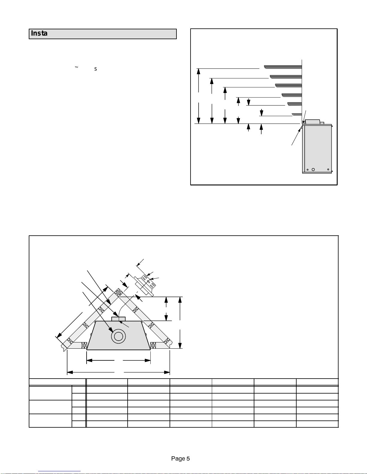
Installation Clearances
MANTEL CLEARANCES
Inches (mm)
Clearances to Combustibles
TheLennoxMerit
t
Seriesventedfireplaces /ventedfireplace heaters are approved with zero clearance to combustible materialsonall sides (as detailedin table 2),with
the following exception: When the unit is installed with
one sideflushwithawall, the wall on theothersideof the
unit must not extend beyondthe front edge of the unit. In
addition, when the unit is recessed, the side walls surrounding the unit must not extend beyond the front edge
of the unit. See figure 2.
Mantel Clearances
Vertical installation clearances to combustible mantels
varyaccordingto thedepthofthemantel. Figure3 details
these required clearances. Mantels constructed of noncombustible materials may be installed at any height
above the appliance opening; however, do not allowanything to hang below the eyebrow.
NOTE -Paint or lacquerusedto finishthemantel mustbe
heat resistant in order to avoid discoloration.
12 (305) MANTEL
10 (254) MANTEL
8 (203) MANTEL
14
(356)
12
(305)
10
(254)
8
(203)
6
(152)
NOTE -Eyebrow shown as positioned
in louvered front model. The eyebrow
position in the flush faced front model
is lower than shown.
6 (152) MANTEL
4 (102) MANTEL
2 (51) MANTEL
4
(102)
TOP OF
APPLIANCE
FIGURE 3
Corner Installations
Units installed across the corner of two joining walls require a minimum diagonal span as detailed in figure 4.
This span accommodates the unit depth.
CORNER INSTALLATIONS
Top (DT/DTH) or Rear (DR/DRH) Vent Application
7in.
Back wall of chase/enclosure
(including any finishing materials)
DR/DRH
DT/DTH
C
Model No. A B C D E F
DT/DTH/DR/DRH 3025
DT/DTH/DR/DRH 3530
DT/DTH/DR/DRH 4035
in.
mm
in.
mm
in.
mm
30-1/8 57-1/2 40-5/8 13-1/2 28-3/4 5
765 1461 1032 343 730 127
35-1/8 57-1/2 40-5/8 13-1/2 28-3/4 5
892 1461 1032 343 730 127
40-1/8 61-3/16 43-11/32 15-7/16 30-11/16 6-3/8
1019 1554 1101 392 779 162
F
A
B
(178 mm)
RECTANGULAR
TERMINATION
b
NOTE -
D
a
Venting requirements for DR/DRH Units (Rear Vent Units)
in corner installations -
- The rectangular termination must be used.
- For the 3025, 3530, and 4035 models, the horizontal vent
E
length “a” to “b,” must not exceed 28 in. (711mm).
FIGURE 4
Page 5
Page 6
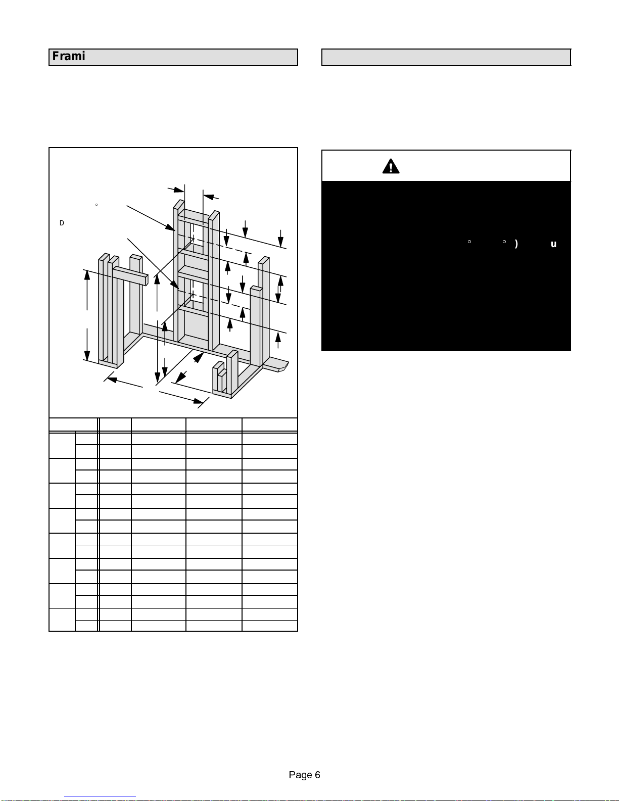
Framing
Installation
Wood or metal framing must accommodate unit outer
shell as shown in figure 5. If unit is to be elevated above
floor level, a solid platform providing continuous support
(e.g. plywood decking) must be constructed.
FRAMING
Framing should be constructed of
2x4 or larger lumber.
DT/DTH VENT FRAMING -
TOP VENT WITH ONE
_
ELBOW
90
DR/DRH VENTFRAMING -
REAR VENTWITH
NO ELBOWS
B
Inches (mm)
Model No. A B C D
DR/
in. 30-1/4 33-1/4 18-1/4 ----
DRH
mm 768 845 464 ----
3025
DR/
in. 35-1/4 35-1/4 20-1/4 ----
DRH
mm 895 895 514 ----
3530
DR/
in. 40-1/4 40-1/4 25-1/4 ----
DRH
mm 1022 1022 641 ----
4035
in. 45-1/4 40-1/4 25-1/4 ----
DR
DR
4540
mm 1149 1022 641 ----
DT/
in. 30-1/4 33-1/4 ---- 38-1/4
DTH
mm 768 845 ---- 972
3025
DT/
in. 35-1/4 35-1/4 ---- 40-1/4
DTH
mm 895 895 ---- 1022
3530
DT/
in. 40-1/4 40-1/4 ---- 45-1/4
DTH
mm 1022 1022 ---- 1149
4035
in. 45-1/4 40-1/4 ---- 45-1/4
DT
DT
4540
mm 1149 1022 ---- 1149
D
C
15-7/8
(403)
A
10-1/2
(267)
5-1/8
(130)
5-1/8
(130)
(178)
7
(178)
7
12-1/8
(308)
12-1/8
(308)
FIGURE 5
Installation should beperformedbyaqualified technician
according to these instructions and local codes.
1 - Carefully remove assembled vented fireplace /
vented fireplace heater from packaging and place in
desired location.
WARNING
Combustible materials may be installed flush with
both sides and top front edges of the fireplace.
Combustible materials must NEVER overlap the
edges onto the front face of the appliance. Joints
between the finished wall and the fireplace edges
_
can only be sealed with a 300
sealant.
Non-combustible materials can be used to cover
the gap between the combustible wall materials
and t he fireplace. On flush-faced models, noncombustiblematerialsmay coverthe upperportion
of thetoppanel down to,butnot beyond the top of,
the eyebrow. You must not modify the air inlet or
outlet grills in any way. Access to panels must not
be obstructed.
2 - Lift and r emove the bus tle; in flus h-faced model
applications, remove the top panel; in louveredface model applications, remove the louvers.
3 - Lower the bottom hinged panel. Remove three se-
curing screwsatthe bottom oftheglass panel.Care-
fully lift and remove the shrink-wrapped glass panel/
log set assembly. Lay the assembly down, and cut
and remove the shrink-wrapping.
4 - Position the logs as shown in figure 6 (3025 units),
figure 7 (3530 units), figure 8 (4035 units), or figure
9 (4540 units). Handle logs carefully, to prevent
breakage. The logs are notched to accommodate
the burner tube, pilot assembly and each other.
5 - Place rockwool(ember material) as shown in figure 10.
NOTE-Yourapplication maynot requirethe useof all
of the provided rock wool. Reserve remaining rock
wool for replacement, if necessary.
6 - Remove cardboard from pressure relief valves lo-
cated on top of the firebox.
7 - Secureappliancetofloorusingfold-downtabsonthe
sides of the fireplace. Additional holes for securing
screwsarealso providedin thebase ofthe unitunder
the firebox.
F (149_C) minimum
Page 6
Page 7

DT/DTH/DR/DRH 3025 LOG PLACEMENT
Log
Number
3
4
1
Log Stamping
Part Number
1
2
196
195
3 197
4 198
Lennox
Part Number
19L61
19L60
19L62
19L63
Lennox Part Number
2
for entire log set: 18L76
1
2
3
4
FIGURE 6
Page 7
Page 8

DT/DTH/DR/DRH 3530 LOG PLACEMENT
Log
4
Number
3
1
Log Stamping
Part Number
1
2
1910
199
3 1911
4 1912
Lennox
Part Number
19L65
19L64
21L10
21L11
Lennox Part Number
for entire log set: 18L77
2
1
2
3
4
FIGURE 7
Page 8
Page 9

DT/DTH/DR/DRH 4035 LOG PLACEMENT
3
4
5
6
Log
Number
Log Stamping
Part Number
1 1919
2 1918
3 1920
1
2
4
5
6
1921 19L70
1922 19L71
1923
Lennox Part Number
Lennox
Part Number
19L67
19L66
19L68
19L69
for entire log set: 18L78
1
3
4
2
5 6
FIGURE 8
Page 9
Page 10

DT/DTH/DR/DRH 4540 LOG PLACEMENT
3
4
7
Lennox
Part Number
19L73
19L72
19L68
19L71
19L74
1
2
Log Stamping
Part Number
1925
1924
Log
6
Number
5
3 1920
1
4
5
2
6
7
1921 19L70
1922
1923 19L69
1926
Lennox Part Number
for entire log set: 18L79
1
2
4
3
5
6
7
FIGURE 9
Page 10
Page 11
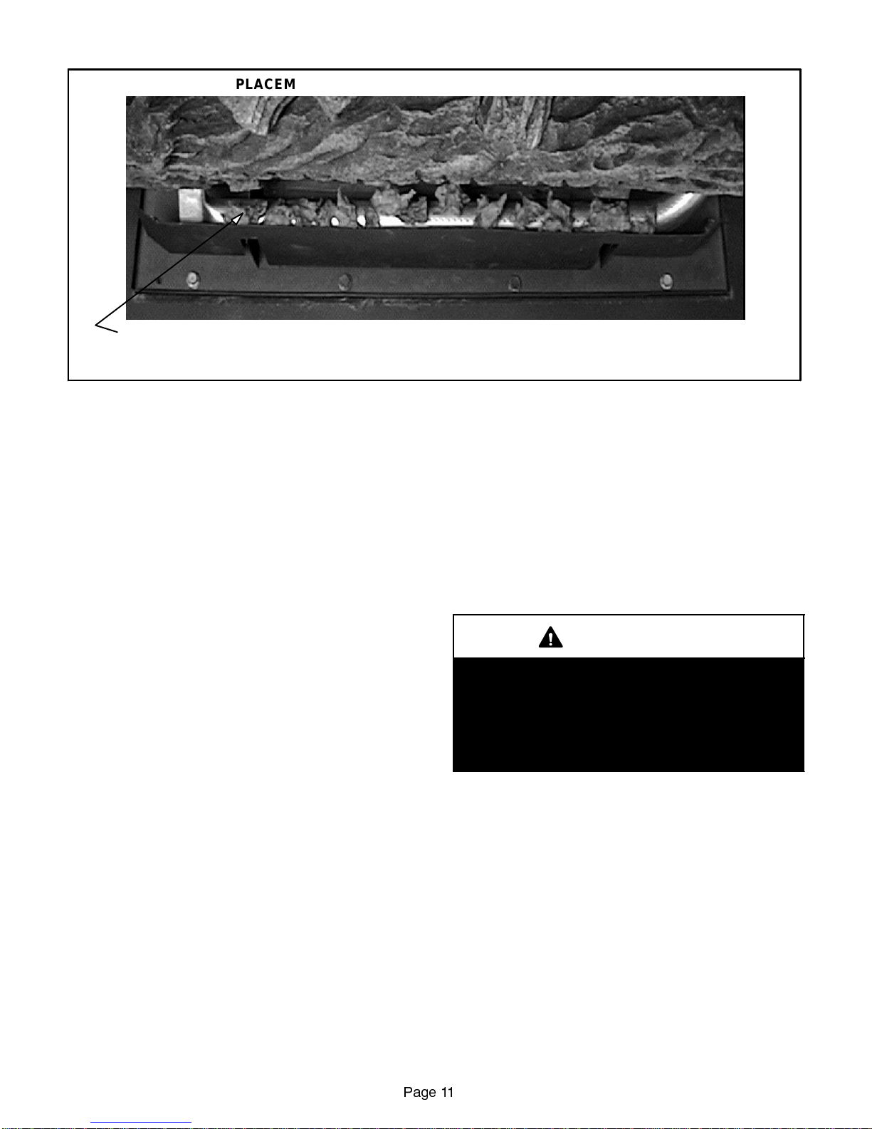
PLACEMENT OF EMBER MATERIAL ON FRONT BURNER
SEPARATE ROCK WOOL INTOPIECES ABOUT THE SIZE OF A NICKEL. KEEP THE PIECES FLUFFED UP, NOT MATTED,
AND PLACE APPROXIMATELY AS SHOWNIN THIS FIGURE.
NOTE - TOO MANY EMBERS ON THE FRONT BURNER WILL CAUSE POOR COMBUSTION.
8- Millivolt Wiring (Millivolt Units) -
In applications where the burner switch is to be unitmounted in the field -
Install the switch in the gas valve mounted bracket
and wire according to figure 37.
In applications where the burner switch is to be wallmounted -
Install a field-provided handy box in a convenient
location adjacenttotheappliance. Install the ON/OFF
switch and faceplate and wire according to figure 37.
In thermostat applications -
Install the thermostat in a suitable location and wire
accordingtofigure37.
9- 24 Volt Wiring (Electronic Ignition Units) -
In applications where the burner switch is to be unitmounted in the field -
Install the ON/OFF switch in the gas valve mounted
bracket and wire according to figure 38.
In applications where the burner switch is to be wallmounted -
Install a field-provided handy box in a convenient
location adjacent to the appliance. Install ON/OFF
switch and faceplate and wire according to figure 38.
In thermostat applications -
Install the thermostat in a suitable location and wire
accordingtofigurefigure38.
10 - 120 Volt Wiring -
MillivoltUnits-120voltwiringisrequired onMillivolt
units only when a fan kit is being installed. Wire fan
kitaccordingtofigure37.
ElectronicIgnition UnitsAll electronic ignitionunits
require120volt wiring.Installwiringaccording to figure 38.
When 120 volt electrical power is applied, the appliance must be electrically grounded according to
FIGURE 10
localcodesor,intheabsenceof localcodes,withthe
current National Electric Code, ANSI/NFPA No. 70,
in theUSAor CSA C22.1 CanadianElectricalCode
in Canada.
11 - Prepare the vent collar for use as indicated in the
venting section. AttacheitherLennox flexible or unitized rigid concentric vent to vent collar, at the top
(DT/DTH units) or rear (DR/DRH units), of the appliance as indicated in the venting section. Ventterminations are indicated in venting section.
12 - Make gaspipingconnections asindicatedin gas pip-
ing section.
WARNING
Do not operate appliance unless glass frame is
properly installed. Glass must not be broken or
cracked. If glass is damaged, rep lace with appropriate glass/frame assemblyavailablethrough
Lennoxrepairparts.Substitutionofanyother than
Lennox-specified glass can lead to property damage or personal injury.
13 - Carefully reinstall the glass door. Tighten the three
bolts at the bottom of the door securely.
14- Install the bustle; in flus h-faced model applica-
tions,install thetoppanel;inlouvered -facemodel
applications, install the louvers.
15 -Remove the ey ebrow from its protec tive wrap-
ping.Slidethe eyebrowintothe slotsonthe lower
edges ofthe radiant panel(flush-facedmodelapplications) or the lower edges of the c abinet top
(louvered-face model applications).
NOTE - The eyebrow must be used in all applications.
16 - Continue with theprocedures indicatedinthestart-up
and adjustments section.
Page 11
Page 12

Venting
SECURING RIGID VENT PIPE TO COLLAR
General Requirements
These instructions shouldbe used as a guideline and do
notsupersedelocal codes inany way.Installventaccord-
ingtolocal codes, theseinstructions,thecurrentNational
Fuel Gas Code (ANSI-Z223.1) in the USA or the current
standards of CAN/CGA-B149.1 and -B149.2 in Canada.
This gas fireplace is equipped with a concentric ventcollar for ease of installation. The concentric vent pipe will
bring in outdoor air for combustion and will remove exhaust gases. Vent terminations are ordered separately.
This Lennox gas fireplace is for use only with Lennox
approved concentric vent pipe: rigid vent pipe in vertical
venting applications, and rigid or flexible vent pipe in
horizontal applications. Each vent must be terminated
using a Lennox vent termination. Approved venting kits
and components are listed on page 26 of this manual.
NOTE - The vent terminations are certified for use
with thisunit and mustbe installed withoutmodification.
APPLYONLY LENNOX MILL-PAC BLACKHIGH
TEMPERATURE SEALANT (Catalog No. 10K81)
AND SLIDE RIGID PIPE OVER INNER AND
NOTE - The bottom part of
the outerpipe is omitted in
order toshow the detail of
OUTER COLLARS.
the innerpipe.
USE THREESCREWS TO
SECURE OUTERVENT
PIPE TO OUTERCOLLAR
RIGID VENT
PIPE
FIGURE 11
Sealing and Connecting Flexible Vent Pipe
Flexible vent pipe is packaged and shipped in its contracted state. When installing flexible vent pipe, its length
may beexpandedto twice itscontractedsize.Youshould
expecttoextenda3ft.sectionofflexiblepipeupto6ft.
IMPORTANT
WARNING
All vent system connections/joints must be properly
sealed using only Lennox MILL-P AC BLACK HIGH
TEMPERA TURE SEALANT, Catalog Number 10K81.
Failure to properly seal the vent system could allow
carbon monoxideleakage resulting ininjuryor death.
Sealing and Joining Rigid Vent Pipe
Apply only Lennox MILL-PAC BLACK HIGH TEMPERATURE SEA LANT (Catalog number 10K81)
around outside of inner and outer vent collars befor e
assembling vent tocollar.Outerpipemust also be secured to outer c ollar using three sheet metal screws.
See figure11.Sealant must beappliedto all rigidpipe
joints and the outer pipe must be secured with thr ee
sheet metal screws.
Under no circumstances, may separate sections of
concentric flexible vent pipe be joined together.
When flexible vent pipe is used, both inner and outer
pipes should be secured to the fireplace concentric
collar and to the vent termination using only Lennox
MILL-PACBLACKHIGHTEMPERATURE SEALANT
(Catalog number 10K81) and metal gear clamps as
shown in figure 12.
SECURING VENT PIPE TO COLLAR
NOTE - Part of the outer
pipe is pulled away to show
the detailof the inner pipe.
APPLYONLY LENNOX MILL-PAC
BLACK HIGHTEMPERATURE
SEALANT (Catalog No. 10K81)
AND SLIDEFLEXIBLE PIPE OVER
INNER ANDOUTER COLLARS.
HOLES PROVIDE
SCREWDRIVER ACCESS
FOR TIGHTENING INNER
GEAR CLAMP.
FLEXVENT
GEAR
CLAMPS
OUTER
COLLAR
FIGURE 12
Page 12
Page 13

Vertical Venting Through the Roof
This Lennox gas fireplace is for use only with Lennox
approved concentric vent pipe; only rigid vent pipe may
be used when vertically venting the fireplace through
the roof.
DT/DTH Applications- See figures 16,17, or 18 forvent
length requirements using concentric vent pipe.
DR/DRHApplications- Seefigures 19,20,or21for vent
length requirements using concentric vent pipe.
DT/DTH and DR/DRH Applications -
Figure15provides adetailoftheverticalvent termination.
Figure 22showstheminimum vent termination height requirements above a flat or sloped roof.
General guidelines for vertical vent installations:
1- DT/DTH Models -
Install aventrestrictor(provided) intheflue outlet as
shown in figure 13.
VENT RESTRICTOR INSTALLATION
(DT/DTH UNITS ONLY)
RESTRICTOR
RESTRICTOR
FLUSH
CABINET TOP
INNER
COLLAR
OUTER
COLLAR
2- Horizontal sections of the vent pipe run should
besloped upwarda minimumof 1/4in. perfoot of
horizontal vent in the direction away from t he
fireplace. In addition, horizontal sections of pipe
must be supported using metal straps spaced
every 2 ft.
3 - Maintain proper clearances any time vent pipe must
passthroughinsulated spaces. Useinsulationshield
when vent pipe passes through any insulation.
_
4- Two45
elbows may be used in place of one 90_elbow. This can only occur once in the entire venting
system.
One45
_
elbowmay besubstitutedfor one90_elbow
at any point in the venting system.
The same rise to run ratios as shown in the venting
_
figures must be followed if 45
elbows are used.
FIRESTOP / SPACER
(Vertical Applications Shown)
NOTE - Horizontal applications require 3 inch
(76mm) clearance above
top of vent.
FIGURE 14
TOPFLUEOUTLET
WHEN USING THE TOP FLUE OUTLETIN VERTICAL VENTING
APPLICATIONS, INSTALL RESTRICTOR FLUSH WITH FLUE
COLLAR OUTLET.
SIDE VIEW
FIGURE 13
1 - Provide a firestop / spacer any time vent pipe must
pass throughacombustiblefloor, ceilingorwall. See
figure14.Refer tolistingon page26 forcatalognumbers of Lennox firestop spacers.
VERTICAL TERMINATION DETAIL
LENNOX MILL-PAC
BLACK HIGH
TEMPERATURE
SEALANT
(Catalog Number 10K81)
RIGID VENT
FIGURE 15
Page 13
Page 14

DT/DTH VERTICAL VENTING FIGURES
VERTICAL VENTING WITHOUT ELBOWS
(DT/DTH - Top Vent Units)
Firestop/Spacermust beused anytime
vent pipe passes through combustible
floor or ceiling or wall.
V = 40 feet
Maximum
V
Install flashing and storm
collar at the point the vent pipe
passes through the roof.
VERTICAL VENTING USING TWO 90_ELBOWS
(DT/DTH - Top Vent Units)
H
Firestop/Spacermust beused any
time vent pipe passes through
combustible floor or ceiling or wall.
V2
V1
V1 + V2 = 40 ft. Maximum.
H = 17 ft. Maximum.
V1 H
1ft.min. 3ft.max.
2ft.min. 6ft.max.
3ft.min. 9ft.max.
4 ft. min. 12 ft. max.
5 ft. min. 15 ft. max.
17 ft. max.6ft.min.
FIGURE 16
V1 + V2 = 40 ft. Maximum.
H1 + H2 = 17 ft. Maximum.
V1 H1 + H2
1ft.min. 3ft.max.
2ft.min. 6ft.max.
3ft.min. 9ft.max.
4 ft. min. 12 ft. max.
5 ft. min. 15 ft. max.
6 ft. min. 17 ft. max.
VERTICAL VENTING USING THREE 90
(DT/DTH - Top Vent Units)
Firestop/Spacermust beused any
V2
H2
time vent pipe passes through
combustible floor or ceiling or wall.
H1
_
ELBOWS
FIGURE 17
V1
FIGURE 18
Page 14
Page 15

DR/DRH VERTICAL VENTING FIGURES
VERTICAL VENTING USING ONE 90_ELBOW
(DR/DRH - Rear Vent Units)
Firestop/Spacermust beused any
time vent pipe passes through
combustible floor or ceiling or wall.
V
H
V+H = 40 ft. MAX.
H = 8 ft. MAX.
VH
1ft.min. 2ft.max.
2ft.min. 4ft.max.
3ft.min. 6ft.max.
4ft.min. 8ft.max.
FIGURE 19
VERTICAL VENTING USING TWO 90_ELBOWS
(DR/DRH - Rear Vent Units)
Firestop/Spacermust beused any
time vent pipe passes through
combustible floor or ceiling or wall.
V
H1
H2
VH1+H2
1ft.min. 2ft.max.
2ft.min. 4ft.max.
3ft.min. 6ft.max.
4ft.min. 8ft.max.
40 ft. max. 8 ft. max.
FIGURE 20
V1 + V2 =40 ft. Maximum.
H1 = 8 ft. Maximum
H1 + H2 = 17 ft. Maximum.
V1 H1
1ft.min. 2ft.max. 3ft.max.
2ft.min. 4ft.max.
3ft.min. 6ft.max.
4ft.min. 8ft.max.
5ft.min. 8ft.max.
6ft.min. 8ft.max.
H1 + H2
6ft.max.
9ft.max.
12 ft. max.
15 ft. max.
17 ft. max.
VERTICAL VENTING USING THREE 90_ELBOWS
(DR/DRH - Rear Vent Units)
H2
Firestop/Spacermust beused any
time vent pipe passes through
combustible floor or ceiling or wall.
V2
V1
H1
FIGURE 21
Page 15
Page 16
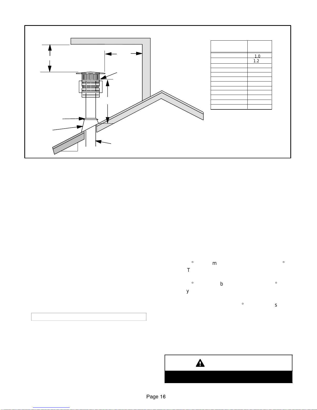
Horizontal Overhang
TERMINATION HEIGHTS FOR VENTS ABOVE
FLAT OR SLOPED ROOFS
2FTMIN.
2FTMIN.
Vent
Termination
Lowest
Discharge
Opening
H*
Storm Collar
*H = MINIMUM HEIGHT FROM ROOF
Flashing
X
12
Roof Pitch is X/12
TO LOWEST DISCHARGE OPENING
Concentric Vent Pipe
FIGURE 22
Detailed steps for installation of the vertical vent at
and above the roof:
1 - Determine the location of the vent’s penetration of
the roof.
2 - Coverthe openingsoftheconcentricventandcutthe
hole in the roof large enough in order to provide a
minimum of one inch (25.4mm) clearance to roof
combustible material.
3 - Frame the vent hole (with material of at least the
same dimensions as the roof rafters) in order to provide adequate nailing support for the roof-to-vent
flashing. (Note - Vent assembly above the roof may
be subjected to high winds).
4 - Install the remaining vent sections and the vent ter-
mination. See figure 22 for minimum allowable termination heights above theroofandminimumallowable clearances to obstacles above the roof.
5 - Use both flashing and a storm collar at the point
where the vent pipe exits the roof. Seal flashing to
roof, and storm collar to vent with non-hardening
caulking compound.
Horizontal Venting Through a Side Wall
This Lennox gas fireplace is for use only with Lennox
approved concentric vent pipe; either rigid or flexible
vent pipe may be used when horizontally venting the
fireplace through a side wall.
DT/DTH Applications- See figures 23,24, or 25 forvent
length requirements using concentric vent pipe.
DR/DRHApplications- Seefigures 26,27,or28for vent
length requirements using concentric vent pipe.
Also, see figure 4 for venting in a corner installation.
Vertical
Wall
OF VENT
ROOF PITCH
FLAT TO 6/12
6/12 TO 7/12
7/12 TO 8/12
8/12 TO 9/12
9/12 TO 10/12
10/12 TO 11/12
11/12 TO 12/12
12/12 TO 14/12
14/12 TO 16/12
16/12 TO 18/12
18/12 TO 20 /12
20/12 TO 21/12
H-FT
1.0
1.25
1.5
2.0
2.5
3.25
4.0
5.0
6.0
7.0
7.5
8.0
General guidelines for horizontal vent installations:
1 - Provide a firestop / spacer any time vent pipe must
pass throughacombustiblefloor, ceilingorwall. See
figure14.Refer tolistingon page26 forcatalognumbers of Lennox firestop spacers.
2- Horizontal sections of the vent pipe run should be
sloped upwarda minimum of 1/4in.per foot of horizontal vent in the direction away from the fireplace.
In addition,horizontalsections of pipe mustbesupported using metal straps spaced every 2 ft.
3 - Maintain proper clearances any time vent pipe must
passthroughinsulated spaces. Useinsulationshield
when vent pipe passes through any insulation.
_
4- Two45
elbows may be used in place of one 90_elbow. This can only occur once in the entire venting
system.
One45
_
elbowmay besubstitutedfor one90_elbow
at any point in the venting system.
The same rise to run ratios as shown in the venting
_
figures must be followed if 45
elbows are used.
5 - The longest length of flexible vent pipe available is 48
inches, measured wheninits compressed form. Flexible vent pipe may not be applicable in every venting
configuration depicted in figures 23, 24, 25, 27, and
28, depending on the total vent length required.
IMPORTANT
Under no circumstances, may separate sections of
concentric flexible vent pipe be joined together.
Page 16
Page 17
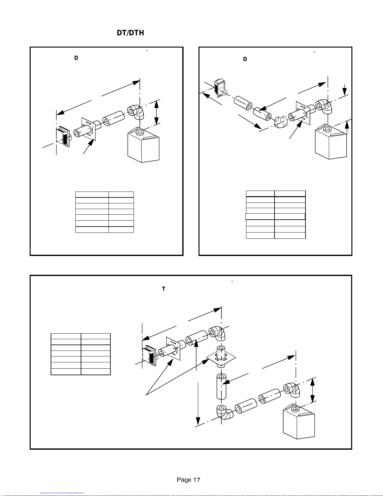
DT/DTH HORIZONTAL VENTING FIGURES
HORIZONTAL VENTING USING ONE 90_ELBOW
(DT/DTH - Top Vent Units)
RIGID VENT PIPE SHOWN; **FLEXIBLE VENT
Rectangular termination shown;
round termination may also be used.
Firestop/Spacermust beused any
time vent pipe passes through
combustible floor or ceiling or wall.
**NOTE: THE LONGEST LENGTH OF FLEX AVAILABLE
IS 48INCHES OFCOMPRESSED FLEX.
PIPE MAY ALSO BE USED.
H
* 10-1/2 in. min. forflexible vent pipe.
VH
*1 ft. min.
2ft.min.
3ft.min.
4ft.min.
3ft.max.
4ft.max.
6ft.max.
8ft.max.
5 ft. min. 17 ft. max.
20 ft. max. 17 ft. max.
HORIZONTAL VENTING USING TWO 90_ELBOWS
(DT/DTH - Top Vent Units)
RIGID VENT PIPE SHOWN; **FLEXIBLE VENT
V
Firestop/Spacermust beused any
combustible floor or ceiling or wall.
**NOTE: THE LONGEST LENGTH OF FLEX AVAILABLE
IS 48INCHES OFCOMPRESSED FLEX.
PIPE MAY ALSO BE USED.
H1
H2
time vent pipe passes through
Rectangular termination shown;
round termination may also be used.
* 10-1/2 in. min. forflexible vent pipe.
V1
*1 ft. min.
2ft.min.
3ft.min.
4ft.min.
5ft.min.
6ft.min.
H1 + H2
3ft.max.
6ft.max.
9ft.max.
12 ft. max.
15 ft. max.
17 ft. max.
20 ft. max. 17 ft. max.
V1
FIGURE 23
HORIZONTAL VENTING USING THREE 90_ELBOWS
V1 + V2
2ft.min.
3ft.min.
4ft.min.
5ft.min.
6ft.min.
20 ft. max. 17 ft. max.
*NOTE: THE LONGEST LENGTH OF FLEX AVAILABLE
IS 48INCHES OFCOMPRESSED FLEX.
Rectangular termination shown;
round termination may also be used.
H1 + H2
4ft.max.
6ft.max.
8ft.max.
15 ft. max.
17 ft. max.
Firestop/Spacermust beused any
time vent pipe passes through
combustible floor or ceiling or wall.
(DT/DTH - Top Vent Units)
RIGID VENT PIPE SHOWN; *FLEXIBLE VENT
PIPE MAY ALSO BE USED.
H2
V2
FIGURE 24
H1
V1
FIGURE 25
Page 17
Page 18
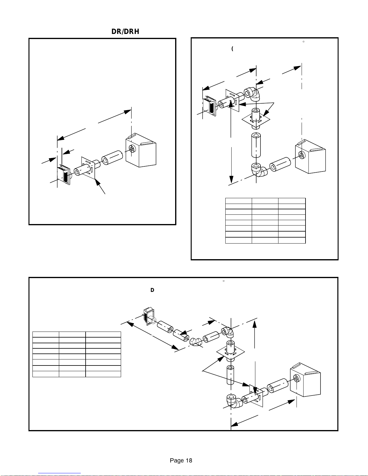
DR/DRH HORIZONTAL VENTING FIGURES
HORIZONTAL VENTING WITHOUT ELBOWS
(DR/DRH - Rear Vent Units)
ONLYTHE RECTANGULAR TERMINATION MAY BE USED.
RIGID VENT PIPE SHOWN; FLEXIBLE VENT PIPE
MAYALSOBEUSED.
**For 3025, 3530, and 4035 models
H = 28 in. (711 mm) Maximum.
**For 4540 models
H = 18 in. (457 mm) Maximum.
**H
7in.
Firestop/Spacermust beused any
time vent pipe passes through
combustible floor or ceiling or wall.
FIGURE 26
HORIZONTAL VENTING USING TWO 90_ELBOWS
(DR/DRH - Rear Vent Units)
RIGID VENT PIPE SHOWN; *FLEXIBLE VENT
*NOTE: THE LONGEST LENGTH OF FLEX AVAILABLE
IS 48INCHES OFCOMPRESSED FLEX.
PIPE MAY ALSO BE USED.
H2
H1
Firestop/Spacermust beused any
time vent pipe passes through
combustible floor or ceiling or wall.
V
Rectangular termination shown;
round termination may also be used.
VH1
H1 + H2
1ft.min. 2ft.max. 3ft.max.
2ft.min. 4ft.max.
3ft.min. 6ft.max.
4ft.min. 8ft.max.
5ft.min. 8ft.max.
6ft.min. 8ft.max.
20 ft. max. 8 ft. max.
6ft.max.
9ft.max.
12 ft. max.
15 ft. max.
17 ft. max.
17 ft. max.
HORIZONTAL VENTING USING THREE 90_ELBOWS
Rectangular termination shown;
round termination may also be used.
V
H1
H1 + H2 + H3
1ft.min. 2ft.max. 3ft.max.
2ft.min. 4ft.max.
3ft.min. 6ft.max.
4ft.min. 8ft.max.
5ft.min. 8ft.max.
6ft.max.
9ft.max.
12 ft. max.
15 ft. max.
6 ft. min. 8 ft. max. 17 ft. max.
20 ft. max. 8 ft. max.
*NOTE: THE LONGEST LENGTH OF FLEX AVAILABLE
IS 48INCHES OFCOMPRESSED FLEX.
17 ft. max.
RIGID VENT PIPE SHOWN; *FLEXIBLE VENT
FIGURE 27
(DR/DRH - Rear Vent Units)
PIPE MAY ALSO BE USED.
H2
H3
V
Firestop/Spacermust beused any
time vent pipe passes through
combustible floor or ceiling or wall.
H1
FIGURE 28
Page 18
Page 19
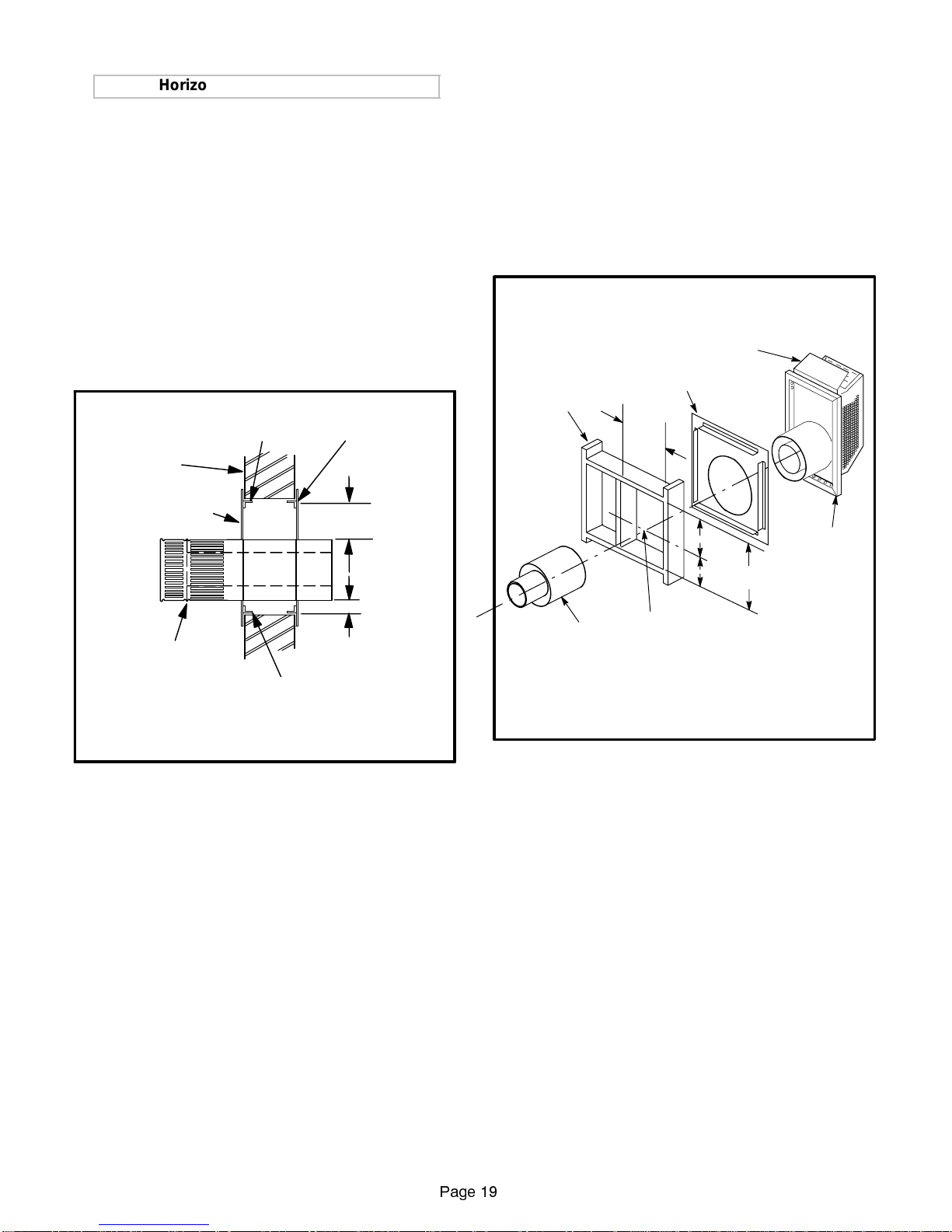
Horizontal Vent Terminations
In the United States, refer to local codes, ANSI Z223.1, and
theventclearanceschartindicated infigure31 forhorizontal
vent termination requirements. In Canada, refer to local
codes, CAN / CGA B149.1 or .2, and the vent clearances
chart indicated in figure 31.
Therectangularvent termination maybeinstalled directly
on the fireplace vent collar. The termination can be adjusted to accommodate wall thicknesses from 5 in.
(127mm) to 9 in.(229mm).Inapplicationswithwall thicknessesrangingfrom9in.(229mm)to13in.(330mm),use
extension JVEXT4 (Catalog Number 12L01) between
Both round (figure 29) and rectangular (figure 30)
vent t erminations are available for use in horizontal
applications. However, the rectangular termination
detailed in figure 30 istheonlyoneapproved for use
inapplications withoutelbowsas detailedinfigure26
or in corner installations as shown in figure 4.
ROUND HORIZONTAL VENT TERMINATION
3 in.(76mm) SPACER INTEGRAL
TO VENT TERMINATION AT TOP
OUTSIDE
WALL SURFACE
FACEPLATE INTEGRAL
TO VENT TERMINATION
VENT TERMINATION
1 in.(25mm) SPACER INTEGRAL TO VENT
Note -
The termination faceplate shall not be recessed into a
wall or siding.
TERMINATIONAT BOTTOM AND SIDES
FIRESTOP / SPACER
ATINSIDE WALLSURFACE
3 in. (76mm)
1in.
(25mm)
fireplace vent collar and termination.
RECTANGULAR VENT TERMINATION
(Shown with rigid vent pipe)
INCHES (mm)
HEATDEFLECTOR
FIRESTOP / SPACER
(See Note 1)
FRAMING
10-1/2
(267)
7
(178)
5-1/8
12-1/8
(130)
(308)
HORIZONTALVENT
Notes 1 - The firestop/spacer may be installed on either side
of the vent framing (interior or exterior side).
2 - The termination base shall not be recessed into a
wall or siding.
CENTER OF VENT
TERMINATION
BASE
(See Note 2)
FIGURE 29
FIGURE 30
Page 19
Page 20
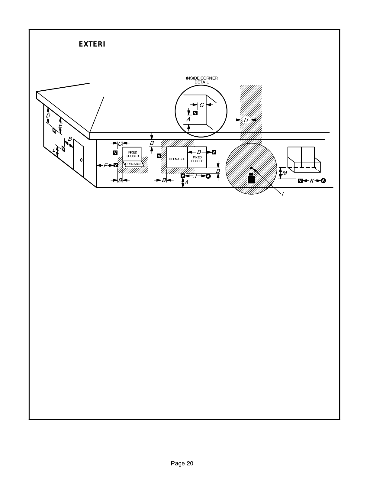
EXTERIOR HORIZONTAL VENT TERMINATION CLEARANCES
A - Clearance above grade, veranda, porch, deck, orbalcony
-- *12 in. (305mm) minimum.
B - Clearance to openable window or door --*12 in. (305mm)
minimum.
C - Clearance to permanently closed window -- minimum 9 in.
(228mm)intheUnitedStatesand12in.(305mm)inCanada
recommended to prevent condensation on window.
D - Vertical clearanceto ventilated soffitlocated abovethe ter-
minalwithinahorizontaldistance of18 in. (457mm)fromthe
center line of the terminal -- 18 in. (457mm) minimum.
E - Clearance to unventilated soffit -- 12in. (305mm) minimum.
F - Clearance to outside corner -- 5 in. (127mm) minimum.
G - Clearance to inside corner -- 6 in. (152mm) minimu m).
†A vent shall notterminate directlyabove asidewalk orpaved drivewaywhich islocated betweentwo
single family dwellings and serves both dwellings.*
‡Only permitted if veranda,porch, deck, or balcony is fully open on aminimumof two sides beneath
the floor.*
*As specified in CAN/CGA B149 Installation Codes.
NOTE - Local codes or regulations may require different clearances.
H - *Nottobeinstalledaboveameter/regulatorassemblywith-
in3ft.(.9m)horizontally fromthecenterlineofthe regulator.
I - Clearance to service regulator vent outlet -- 3 ft. (915mm)
in the UnitedStates and *6ft. (1.8m) in Canada minimum.
J - Clearance to non-mechanicalair supply inlet tobuilding or
the combustion air inlet to any other appliance -- 9 in.
(228mm)in theUnitedStatesand*12 in.(305mm) in Canada minimum.
K - Clearance tomechanicalair supply inlet-- 3ft. (915mm)in
the United States and *6 ft. (1.8m) in Canada minimum.
L - †Clearance above pavedsidewalk ora paveddriveway lo-
cated on public property -- *7 ft. (2.1m) minimum.
M - ‡Clearance under veranda,porch,deck,or balcony--12in.
(305mm) minimum.
N - Vent termination must not be located in a recessed area.
FIGURE 31
Page 20
Page 21
Gas Piping
In the U.S. and Canada, both flexible and rigid gas pipe
areapprovedforuse with theseappliances.Consult local
codes for gas piping practices.
1 - Lennox gas fireplaces are shipped standard for left
or rightsideorbottom installation of gas piping. Simply connect gas supply to gas valve. Gas valve connection is 3/8 in.
2 - When connecting gas supply,factorssuch aslength
of run, number of fittings and furnace rating (if applicable) must be considered to avoid excessive pressure drop.
3 - Gas piping must not run in or through air ducts,
clotheschutes,chimneys orgas vents,dumbwaiters
or elevator shafts.
4 - Piping should be sloped 1/4 inch per 15 feet upward to-
ward the meter from the appliance. The piping must be
supported at proper intervals (every 8 to 10 feet) using
suitable hangers or straps.
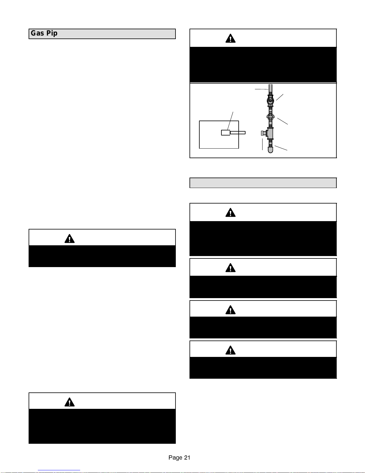
5 - In some localities, codes may require installation of
an equipment shut-off valve and union (both furnished by installer) external to the unit. Union must
be of the ground joint type. See figure 32.
IMPORTANT
Compounds used on threaded joints of gas piping
must be resistant to the actions of liquified petroleum
gases.
NOTE - In case emergency shutoff is required, close equipment shut-off valve and disconnect main power to unit.
These devices should be properly labeled by the installer.
The appliance must be isolated from the gas supply system by closing its equipment shut-off valve during any
pressure testing of the gas supply piping system at test
pressures equal to or less than 1/2 psig (3.48 kPa).
The appliance and its appliance main gas valve must be
disconnected from the gas supply piping system during
anypressuretestingofthegassupplysystem attestpressures in excess of 1/2 psig (3.48 kPa). See figure 32.
LEAK CHECK
After gas piping is completed, carefully check all piping
connections (factory and field) for gas leaks. Use a leak
detecting solution or other preferred means.
CAUTION
Some soaps used for leak detection are corrosive
to certainmetals. Carefully rinse pipingt horoughly
after leak test has been completed. Do not use
matches, candles, flame or other sources of ignition to check for gas leaks.
IMPORTANT
Appliancegasvalves canbe damagedifsubjected
to more than 1/2 psig (3.48 kPa) pressure. Th erefore, when pressure testing the gas supply piping
system in this p ressure range, the applian ce g as
valve must be disconnected and isolated.
GAS SUPPLY PIPING SYSTEM
ISOLATE APPLIANCE
MAIN GASVALVE DURING
TESTING
APPLIANCE
CAP
FIGURE 32
EQUIPMENT
SHUT-OFF VALVE
Equipment shut-off
valve will not holdtest
pressures greaterthan
1/2 psig(3.48kPa).
GROUND
JOINT
UNION
DRIP LEG
Unit Start-up
FORYOURSAFETYREADBEFORELIGHTING
WARNING
Do not use this appliance if any part has been
underwater. Immediately call a qualified service
technician to inspect the fireplace and to replace
any partofthe control system and any gascon t rol
which has been under w ater.
WARNING
If overheating occurs or if gas supply fails to shut
off, close the manual shut-off valve to the appliance
before shutting off electrical supply.
CAUTION
Before attempting to perform any service or
maintenance, turn th e electrical po wer to appliance OFF at disconnect swit ch.
WARNING
Do not operate appliance unless glass frame is
properly installed. Glass must not be broken or
cracked.
BEFORE LIGHTING smell all around the appliance area
for gas. Be sure to smell next to the floor because some
gas is heavier than air and will settle on the floor.
Use only your hand to turn the gas control knob. Never use
tools. If the knob will not turn by hand, do not try to repair it,
call a qualified service technician. Force or attempted repair
may result in a fire or explosion.
Page 21
Page 22
WARNING
If youdo not followtheseinstructionsexactly,a fire
or explosion may result causing property damage,
personal injury or loss of life.
PLACING FIREPLACE INTO OPERATION
(Millivolt Valves with Piezo Ignitor)
Fireplaces which include a millivolt valve are equipped
with a pilotwhichmustbelitbya Piezo ignitor (red ignitor
button). When lighting the pilot, follow these instructions
exactly.
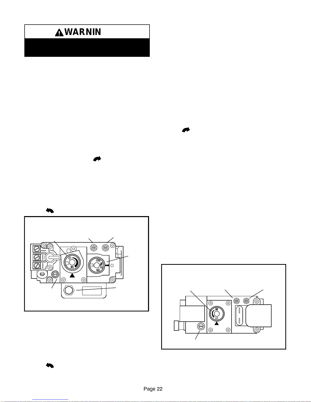
GAS VAL VE OPERATION - Millivolt Valve (Figure 33)
1- STOP! Read the safety information at the beginning
of this section.
2- TurnOFF theburnerswitch(ifapplicable),orsetthe
thermostat to the lowest setting (if applicable).
3 - Turn off all electrical power to appliance.
4 - Open the bottom panel. Push in gas control knob
slightly and turn clockwise
NOTE - Knob cannot be turned from PILOT to OFF
unless knob is pushed in slightly. Do not force.
5 - Wait five (5) minutes to clear out any gas. If you then
smell gas, STOP! Immediately call your gas supplier
from a neighbor’s phone. Follow the gas supplier’s instructions. If you do not smell gas go to next step.
6 - Presspartiallyandturngasvalveknob counterclock-
wise
to PILOT.
MILLIVOLT GAS VALVE
(Optional manually-modulated gas valve shown)
HI/LO FLAME
ADJUSTMENT KNOB
PILOT
ADJUSTMENT
SCREW
MANIFOLD
GAUGE PORT
to OFF.
PUSH-BUTTON
SUPPLY
GAUGE PORT
CONTROL
KNOB
PIEZO
IGNITOR
10- Turn ON the burner switch (if applicable), or set the
thermostat to the desired setting (if applicable).
11- Close the bottom panel.
NOTE - If gas valve is turned to OFF from ON or PILOT
whileapplianceis in operation,gasvalvewill latch inOFF
position for 25 seconds.
12- If the appliance will not operate, follow the instructions
“Turning OffGastoUnit”andcall your servicetechnician
or gas supplier.
TURNING OFF GAS TO UNIT
1- TurnOFF theburnerswitch(ifapplicable),orsetthe
thermostat to the lowest setting (if applicable).
2 - Turn off all electrical power to appliance.
3 - Open the bottom panel.
4 - Push in gas control knob slightly and turn clock-
wise
to OFF. Do not force.
5 - Close the bottom panel.
PLACING FIREPLACE INTO OPERATION
(Electronic Gas Valves)
Fireplaces equipped withanignition device which will automaticallylighttheburner.Do nottry tolight theburner
by hand. Follow these instructions exactly.
GAS VALVE OPERATION- Electronic Valve (Figure 34)
1- STOP! Read the safety information at the beginning
of this section.
2- TurnOFF theburnerswitch(ifapplicable),orsetthe
thermostat to the lowest setting (if applicable).
3 - Turn off all electrical power to the appliance.
4 - This appliance is equipped with an ignition device
which automatically lights the burner. Do not try to
light the burner by hand.
5 - Wait five (5) minutes to clear out any gas. If you then
smell gas, STOP! Immediately call your gas supplier
from a neighbor’s phone. Follow the gas supplier’s in-
structions. If you do not smell gas go to next step.
ELECTRONIC GAS VALVE
(Optional manually-modulated gas valve shown)
HI/LO FLAME
ADJUSTMENT
KNOB
MANIFOLD
GAUGE PORT
SUPPLY
GAUGE PORT
GAS VALVE SHOWN IN PILOT POSITION
FIGURE 33
7 - Push control knob in until it stops and hold knob in this
position. Immediately light the pilot by pushing the red
Piezo ignitor button. Continue to press control knob for
25 seconds after the pilot is lit. Release knob. It should
pop back up. Pilot should remain lit. If pilot goes out, repeat steps 5 through 10.
8 - Presspartiallyandturngasvalveknob counterclock-
wise
to ON.
9 - Restore electrical power to appliance (if applicable).
Page 22
PILOT
ADJUSTMENT SCREW
FIGURE 34
6 - Restore electrical power to the appliance.
7- TurnON the burner switch (if applicable), or set the
thermostat to the desired setting (if applicable).
Page 23
8 - If the appliance will not operate, follow the instruc-
tions turning off gas to unit and call a servicetechnician or gas supplier.
TURNING OFF GAS TO UNIT
1- TurnOFF theburnerswitch(ifapplicable),orsetthe
thermostat to the lowest setting (if applicable).
2 - Turn off all electrical power to appliance.
3- TurnOFF gas supply at main manual shut-off valve lo-
cated near the fireplace.
Adjustments
NOTE - The air shutter for theburnerprimary airopening
is factory-set. Do not adjust the factory-set position.
GAS FLOW
This burner / log set has been adjusted for the proper gas
flow at the factory. No adjustment is necessary other than
the pilot flame. See pilot flame adjustment section.
GAS PRESSURE
Check gas inlet pressure with the appliance firing at the
maximum rate. A minimum of 4.5 in. w.c. (1.12 kPa) and
maximum of 7.0in.w.c. (1.74 kPa) fornatural gasshould
be maintained. When LP/Propane gas is used, a minimumof11.0in. w.c.(2.74kPa) andamaximum of 13.0in.
w.c. (3.23 kPa) must be maintained.
Maximum manifold pressure is 3.5 in. w.c. (0.87 kPa)for
naturalgasand 10in. w.c.(2.49kPa)for LP/Propanegas.
HIGH ALTITUDE INSTALLATION
Installations in the USA -
Units are tested and approved for elevations of 0-2000
feet (0-610 meters).
When installing this unit at an elevation above 2000 feet
(610meters),decreasethe inputrateby changing theexisting burner orificetoasmaller size. Input rate should be
reduced 4 percent for each 1000 feet (305 meters) of
elevation above sea level. For assistance in determining
the proper orifice size, check with the local gas utility or
consult the latest edition of the National Fuel Gas Code
(ANSI Z223.1, appendix F).
Installations in Canada -
Units are tested and approved for elevations of 0-4500
feet (0-1372 meters).
When installing this unit at an elevation above 4500
feet(1372meters),consultthelocalauthoritieshaving
jurisdiction.
ELECTRICAL
NOTE-Thesechecksarenecessaryonlyifoptionalblower kit has been applied.
1 - Check all wiring for loose connections.
2 - Check for correct voltage at unit (unit operating).
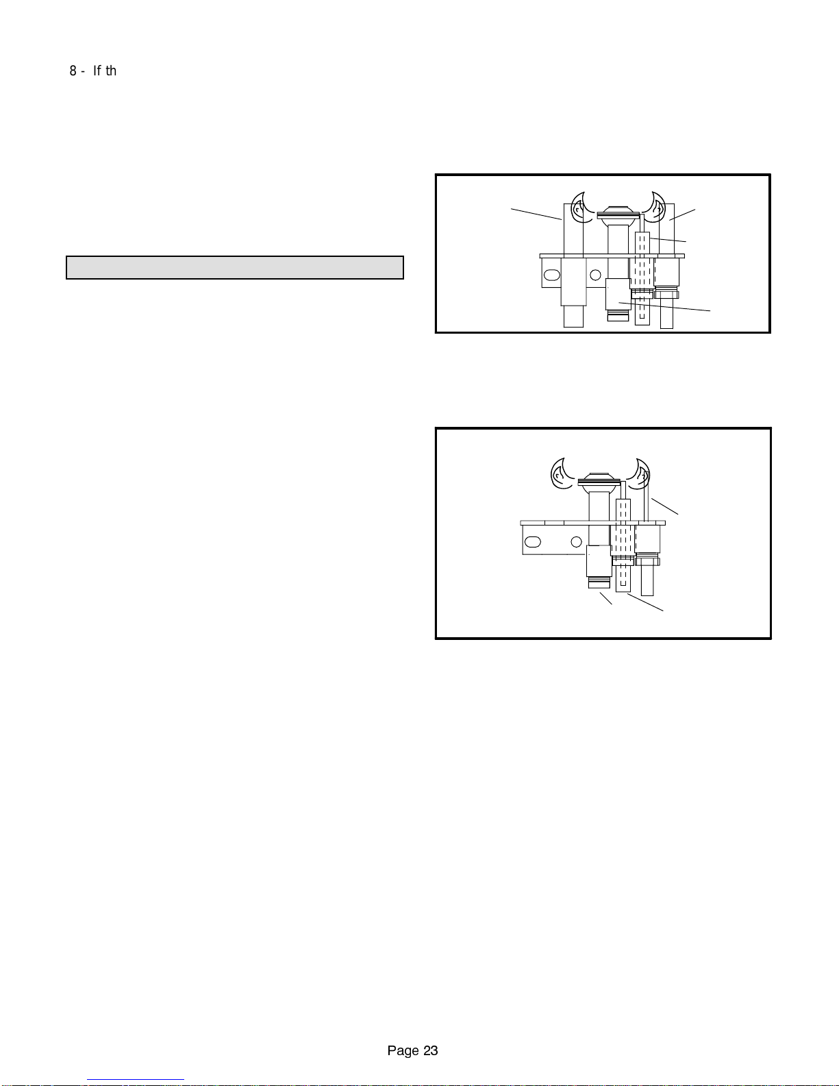
PILOT FLAME ADJUSTMENT
A - Millivolt System
To ensure proper gas valve operation, the pilot flame
should impinge upon both the thermopile and the low
mass thermocouple. See figure 35. The pilot flame adjustment screw is shown in figure 33.
PILOT FLAME - (Millivolt systems)
THERMOPILE
NOTE -Flame must
impinge upon both
thermopile and low
mass thermocouple
to insureproper appliance operation.
LOW MASS
THERMOCOUPLE
PIEZO IGNITOR
PILOT
FIGURE 35
B - Electronic Ignition System
To ensure proper gas valve operation, the pilot flame
shouldimpingeupontheflamesensor.Seefigure 36.The
pilot flame adjustment screw is shown in figure 34.
PILOT FLAME - (Electronic Ignition systems)
FlAME SENSOR
NOTE -Flame mustimpinge
upon flamesensor to insure
proper appliance operation.
IGNITORPILOT
FIGURE 36
BURNER FLAME ADJUSTMENT
The burner flame may be adjusted by turning the HI/LO
knob on the gas valve to obtain the required heating outputandflame appearance.Seefigure 33or34. The burner flame should be inspected at the beginning of each
heatingseasonandburnersshouldbecleanedbyaqualified service technician. The flame colorwillstabilizeafter
15 minutes of operation.
FAILURE TO OPERATE
If unit fails to operate check the following:
1 - Is thermostat calling for heat, if applicable?
2 - Is ON/OFF wall switch in ON position, if applicable?
3 - Is pilot lit, if applicable?
4 - Is gas turned ON at meter?
5 - Is gas valve in ON position (millivolt units)?
6 - Is gas turned ON at the appliance shut-off valve?
7 - Is electr ical power turned ON to the appliance (if
applicable)?
Page 23
Page 24
Service
WARNING
Disconnect power before servicing unit.
Service should be performed by a qualified technician.
Control compartment, burners and circulating air passageways must be kept clean. The appliance should be
inspected annually; however, more frequent cleaning
may be necessary due to excessive amounts of lint or
dust.
At the beginningofeachheatingseason,service items A
to C as described below:
A - BLOWERS (If applicable)
Check and clean blower wheels for any debris. Blower
motorsareprelubricatedfor extendedbearinglife.Nofurther lubrication is needed.
B - VENT TERMINATION
WARNING
Some soaps used for leak detection are corrosive
to certainmetals. Carefully rinse pipingt horoughly
after leak test has been completed. Do not use
matches, candles, flame or other sources of ignition to check for gas leaks.
FIRE BOX
Periodically inspect fire box for corrosion. If necessary,
wipe clean using a damp rag or vacuum using brush attachment.
GLASS / FRAME ASSEMBL Y
Clean inside and outside glass surfaces usinga mild detergent/water solution and a soft cloth. DO NOT use abrasive
cleansers which might scratch the high-temperature glass
surface. DO NOT clean glass when surface is hot to the
touch. Glass cleaner is available as Lennox part number
19N74.
Glass/frame assembly must be properly reinstalled after
service. All three screwsmust be installed and tightened
securely.
Make sure there is no blockage at the vent termination.
C - PILOT AND BURNERS
Inspectpilotand burnerflames.If necessary,lightly brush
burner ports to dislodge any obstructions.
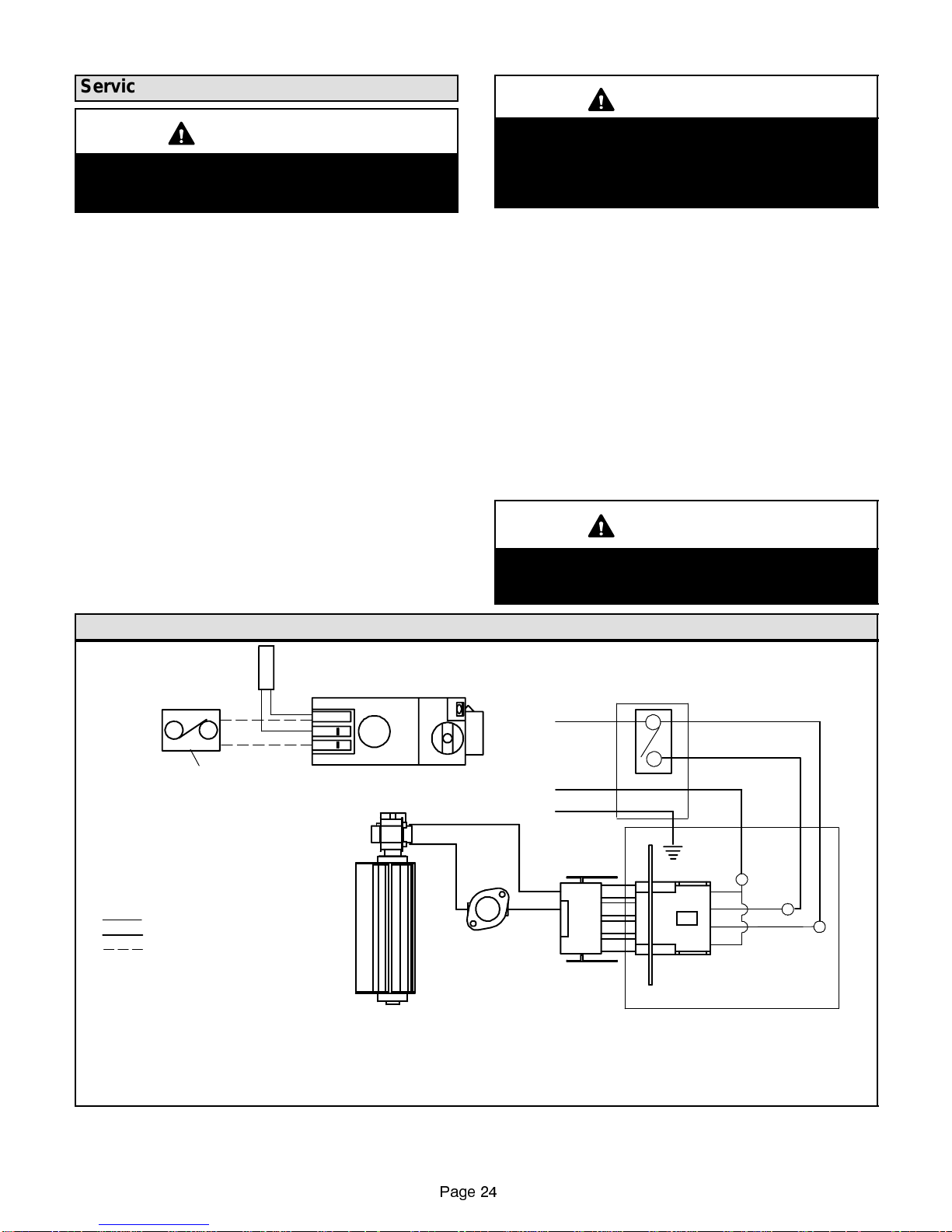
Wiring Diagram - Millivolt Gas Valves
THERMOPILE
TP-TH
TP
TH
BURNER ON/OFF SWITCH
(UNIT-MOUNTED)
OR BURNER ON/OFF SWITCH
(WALL-MOUNTED)
OR THERMOSTAT
(See Note 2)
LEGEND
W-WHITE
BK - BLACK
FACTORY INSTALLED
120V FIELD INSTALLED
MILLIVOLT (See Note 2)
GAS VALVE
TEMP. SENSOR
Do not operate appliance unless glass frame is
properly installed. Glass must not be broken or
cracked.
120 VAC
NEUTRAL
GROUND
WHITE
BLACK
(See Note 1)
BLACK
WHITE
GREEN
BK
CONNECTOR
WARNING
FAN SWITCH
(See Note 1)
W
BK
BK
W
Note 1:
Note 2:
OPTIONAL FAN KITS
Fan Kit FK1 contains Fan only. (Fan Switch is field-provided)
Fan Kit FK2 contains Fan, Temp. Sensor and Fan Switch.
BURNER SWITCHES AND THERMOSTAT
Unit-mounted ON / OFF switch is available as a factory-installed option or can be ordered separately and field-inst alled.
Wall-mounted ON / OFF switch is field-provided;
Thermostat is available as a factory-provided option in vented fireplace heater model installations.
FAN(SeeNote1)
JUNCTION BOX
FIGURE 37
Page 24
Page 25
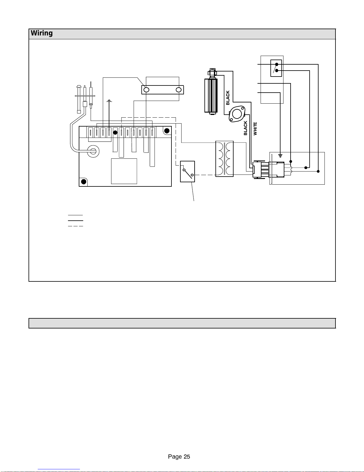
Wiring Diagram - Electronic Gas Valves
A
H
NSWITC
F
(See Note 1)
PILOT BURNER
IGNITOR-SENSOR
ASSEMBLY
PILOT
GAS
SUPPLY
ELECTRONIC
IGNITION
CONTROL
BOARD
Note 1:
OPTIONAL FAN KITS
Fan Kit FK1 contains Fan only. (Fan Switch is field-provided)
Fan Kit FK2 contains Fan, Temp. Sensor and Fan Switch.
Note 2:
BURNER SWITCHES AND THERMOSTAT
Unit-mounted ON / OFF switch is available as a factory-installed option or can be ordered separately and field-inst alled.
Wall-mounted ON / OFF switch is field-provided;
Thermostat is available as a factory-provided option in vented fireplace heater model installations.
BROWN
GROUND
D
LEGEND
W-WHITE
BK - BLACK
FACTORY INSTALLED
120V FIELD INSTALLED
24V (See Note 2)
L
E
ORANGE
2
T
H
S
BK
WHITE
GREEN
YELLOW
EV2
GAS
WHITE
EV1
VALVE
RED
FAN(SeeNote1)
120 VAC.
NEUTRAL
GROUND
TEMP. SENSOR
(See Note 1)
3
1
P
V
4
M
S
E
V
N
S
E
BLUE
24V.
RED
BK
120V.
WHITE
J-BOX
BK
BK
W
W
TRANSFORMER
CONNECTOR
BURNER ON/OFF SWITCH (UNIT-MOUNTED)
OR BURNER ON/OFF SWITCH (WALL-MOUNTED)
OR THERMOSTAT
(See Note 2)
Repair Parts
The following repair parts are available through independent Lennox dealers.Whenorderingparts, it is important to
include the complete appliance model number listed on the Warnock Hersey rating plate.
Cabinet Parts
Heating Parts
Burner tube
Gas manifold
Gas Logs
FIGURE 38
Control Parts
Gas valve
Thermopile (Millivolt models)
Piezo push button ignitor (Millivolt models)
Low mass thermocouple (Millivolt models)
Ignitor
Pilot burner
On/Off switch
Thermostat
Transformer (Electronic ignition models)
Electronic ignition module (Electronic ignition models)
Page 25
Page 26

Venting Kits and Available Components
The following is a list of venting kits and components approved for use with the gas fireplace:
Catalog
Number
96K70 12” Compressed Flex Termination (Round)
96K71 18” Compressed Flex Termination (Round)
96K72 24” Compressed Flex Termination (Round)
96K73 36” Compressed Flex Termination (Round)
96K74 48” Compressed Flex Termination (Round)
98K08 12” Compressed Flex Termination (Square)
98K09 18” Compressed Flex Termination (Square)
98K10 24” Compressed Flex Termination (Square)
98K11 36” Compressed Flex Termination (Square)
98K12 48” Compressed Flex Termination (Square)
96K80 Firestop Spacer - Horizontal Vent
96K82 1’ Coaxial Unitized Rigid Pipe
96K83 2’ Coaxial Unitized Rigid Pipe
96K84 3’ Coaxial Unitized Rigid Pipe
96K85 5’ Coaxial Unitized Rigid Pipe
96K86 1’ Coaxial Adjustable Pipe
96K87 Firestop Spacer - Vertical Vent
96K88 90_Elbow
96K89 45_Elbow
96K90 Flat Roof Flashing
96K91 1/12 - 7/12 Pitched Roof Flashing
97K01 8/12 - 12/12 Pitched Roof Flashing
96K92 Support Plate
96K93 Support Strap
96K94 Attic Insulation Shield
96K95 Horizontal Term. for Rigid Pipe (Round)
96K96 Vertical Term. for Rigid Pipe (Round)
98K13 Horizontal Term. for Rigid Pipe (Square)
12L01 JVEXT4 - 4” Vent Extension
96K13 Circulating Air Fan
96K14 Circ. Air Fan with Temp. Control & Rheostat
96K98 Termination Heat Deflector
96K99 Riser Kit (Flex connections only)
97K00 Wall Termination Heat Guard
10K81 Mill-Pac Black High Temperature Sealant
97K72 30” Grate Kit
97K73 35” Grate Kit
97K74 40” Grate Kit
97K75 45” Grate Kit
96K16 30” 4-Piece Polished Brass Trim Assembly
96K17 35” 4-Piece Polished Brass Trim Assembly
Description
Catalog
Number
96K18 40” 4-Piece Polished Brass Trim Assembly
96K19 45” 4-Piece Polished Brass Trim Assembly
96K20 30” 3-Piece Polished Brass Trim Assembly
96K21 35” 3-Piece Polished Brass Trim Assembly
96K22 40” 3-Piece Polished Brass Trim Assembly
96K23 45” 3-Piece Polished Brass Trim Assembly
96K15 Free-Standing Heat Guard (40/45”Models)
96K30 30” Heat Guard
96K31 35” Heat Guard
96K32 40” Heat Guard
96K33 45” Heat Guard
11K97 Free-Standing Heat Guard (30/35”Models)
96K15 Free-Standing Heat Guard (40/45”Models)
96K34 3/8”Stainless Steel Flex Connector (12”)
96K35 3/8”Stainless Steel Flex Connector (24”)
26N04 Remote Control
98K99 Deluxe Remote Control
60P60 White-Rodgers 1E30W-60 Thermostat (F_)
10N64 White-Rodgers 1E30W-60 Thermostat (C_)
96K09 Brickaded Interior for 30” Rear Vent Units
96K10 Brickaded Interior for 35” Rear Vent Units
96K11 Brickaded Interior for 40” Rear Vent Units
96K12 Brickaded Interior for 45” Rear Vent Units
96K05 Brickaded Interior for 30” Top Vent Units
96K06 Brickaded Interior for 35” Top Vent Units
96K07 Brickaded Interior for 40” Top Vent Units
96K08 Brickaded Interior for 45” Top Vent Units
96K40 On/Off Switch (Unit-mounted)
96K41 Split Logs - 30”
96K42 Split Logs - 35”
96K43 Split Logs - 40”
96K44 Split Logs - 45”
96K45 30” Polished Brass 2-pc. Bustle w/Side Strips
96K46 35” Polished Brass 2-pc. Bustle w/Side Strips
96K47 40” Polished Brass 2-pc. Bustle w/Side Strips
97K48 45” Polished Brass 2-pc. Bustle w/Side Strips
96K49 30” Polished Brass 6-pc. Louvers
96K50 35” Polished Brass 6-pc. Louvers
96K51 40” Polished Brass 6-pc. Louvers
96K52 45” Polished Brass 6-pc. Louvers
Description
Page 26
 Loading...