

Page 1

APPLICATION
GUIDE
CHILLED
WATER CASSETTE
CWC - 2P/4P
English/03-2005
Page 2

INDEX
Index AGU CWC-2P/4P
General Description
Specifications
Performances tables
Sound levels
Options
Dimensions
Unit installation
Electrical connections
Drain pipework
Installation of diffuser and inlet grille
Maintenance
Air distribution
Fault analysis
2
3
4-8
8
9-10
11-12
13-14
15-16
16
17
18-20
20
20
Our company is a member of the Eurovent Certification Programme.
Our products comply with European standards.
Lennox have been providing environmental solutions since 1895, our range of Chilled Water Cassette CWC-2P/4P continues
to meet the standards that have made LENNOX a household name. Flexible design solutions to meet YOUR needs and
uncompromising attention to detail. Engineered to last, simple to maintain and Quality that comes as standard.
Information on local contacts at www.lennoxeurope.com.
All the technical and technological information contained in this manual, including any drawing and technical descriptions
provided by us, remain the property of Lennox and must not be utilised (except in the operation of this product), reproduced,
issued to or made available to third parties without the prior written agreement of Lennox.
1
Page 3

GENERAL DESCRIPTION
CWC
Model
Chilled Water Cassette
The CEILING CASSETTES are designed to operate with chilled and hot water. They provide both cooling and
dehumidification in cooling mode and heating in the latter, cleaning and filtering the air in the process. Electrical
heating elements are available as an option on some units. The units are available with cooling capacities from
1950 to 8450 W and heating capacities from 1400 to 10600 W.
CABINET
The unit chassis is made of galvanised steel and is fully insulated inside.
The units have been designed in order to install them in high ceilings where standard plates 600x600 mm or
600x1200 mm will be used.
DIFFUSER PANEL
Two alternatives can be chosen:
- Plastic diffuser: Made in decorative plastic, with a smooth finish. Internal insulation prevents condensation from
forming. 4 louvres for MODELS 600x600 and 6 louvres for MODELS 600x1200 ensure air distribution.
- Metallic diffuser.
020 (030-040-050-070-090)
Models 600x600: 020-030-040-050
Models 600x1200: 070-090
Close cooling capacity in W x 100
X
1:
Plastic diffuser
2: Metallic diffuser
Y
1: 2 Pipes units
4: 4 Pipes units
HEAT EXCHANGER
Made of copper tubes and aluminium fins. Coils have been designed and manufactured to ensure maximum
efficiency.
FAN
The units are supplied with one (models 600x600) or two (models 600x1200) 3-speed centrifugal fans. The impeller
blades have been designed specifically for this type of units ensuring exceptionally low sound levels and the motor
is protected with internal thermal protection.
AIR DISTRIBUTION
The position of the louvres can be adjusted manually (only for plastic diffuser).
AIR FILTER
A polypropylene washable air filter is incorporated in the unit; it is easily accessible for maintenance.
INTERNAL COMPONENTS
The unit is designed with serviceability in mind, and all components are easily accessible. A drip tray collects
condensate which is removed by means of a condensate pump.
ELECTRIC CIRCUIT
The electrical panel is provided with a terminal block which provides connection to mains power or to a control box
(depending on model).
A fused isolator is not included and where required shall be installed by others.
OPTIONS
Electric heater (depending on model).
Fresh air kit.
- Duct connection.
- Fresh air fan.
- Duct supports.
Air supply to an adjacent room kit.
- Duct connection.
- Duct supports.
Water control valve kit with 2 way or 3 way
proportional control valves.
Auxiliary drip tray.
Thermostat.
Float switch.
Master Slave.
Fitting & testing valves.
Water evacuation security.
2
Page 4

SPECIFICATIONS
CWC - 2P / 4P
Nominal air flow (1)
Total cooling capacity (2)
(2 pipes system)
Total cooling capacity (2)
(4 pipes system)
Sensible cooling capacity (2)
(2 pipes system)
Sensible cooling capacity (2)
(4 pipes system)
Heating capacity (3)
(4 pipes system)
Heating capacity (4)
(2 pipes system)
m3/h
W
W
W
W
W
W
L
M
H
L
M
H
L
M
H
L
M
H
L
M
H
L
M
H
L
M
H
CWC 020
445
550
650
1480
1690
1870
1620
1840
2030
1150
1320
1480
1380
1590
1770
1290
1420
1510
2010
2330
2600
CWC 030
400
517
598
2580
3090
3410
2150
2540
2790
2000
2440
2730
1580
1900
2110
1830
2240
2530
2980
3620
4050
CWC 040
553
670
779
3240
3690
4080
2980
3370
3690
2470
2850
3190
2250
2590
2880
2900
3220
3500
3610
4160
4650
CWC 050
650
791
920
4190
4820
5330
3700
4210
4620
3020
3530
3960
2840
3280
3650
3530
4010
4410
5290
6170
6940
CWC 070
987
1164
1342
6290
7040
7740
5320
5920
6470
4370
4950
5510
4000
4520
5010
5670
6240
6750
6650
7430
8260
CWC 090
1126
1323
1569
6940
7770
8710
6350
7070
7880
5040
5710
6490
4910
5540
6260
6170
6910
7670
8700
9860
1123
Pressure drop (water) (2)
cooling circuit
(2 pipes system)
Pressure drop (water) (2)
cooling circuit
(4 pipes system)
Pressure drop (water) (3)
heating circuit
(4 pipes system)
Pressure drop (water) (4)
heating circuit
(2 pipes system)
Power electrical heater (5)
Fan-motor performance
Weight unit
Weight Plastic diffuser
Weight Metallic diffuser
(6)
kPa
kPa
kPa
kPa
kW
W
A
Kg
Kg
Kg
M
H
M
H
M
H
M
H
M
H
L
L
L
L
L
9.3
11.8
14.2
8.9
11.3
14.1
1.9
2.3
2.5
11.2
14.2
17.0
1.5
48
0.17
0.20
0.22
21
3
5
13.3
18.4
22.0
24.8
33.7
39.8
5.3
7.6
9.4
13.2
18.2
21.8
2
48
0.17
0.20
0.22
22
3
5
25.2
31.8
38.0
18.3
22.8
27.0
24.9
30.2
34.9
26.3
33.3
39.7
2
66
0.26
0.28
0.30
23
3
5
24.2
31.0
37.2
24.5
30.8
36.5
25.4
32.0
38.0
28.9
37.0
44.4
N/A
82
0.29
0.30
0.34
24
3
5
18.1
22.1
26.2
12.9
15.7
18.4
19.8
23.4
27.0
20.4
25.0
29.7
2.5-4
2x66
2x0.26
2x0.28
2x0.30
43
5
11
13.6
16.7
20.6
21.0
25.4
31.0
17.3
21.1
25.5
16.4
20.1
24.8
2.5-4
2x82
2x0.29
2x0.30
2x0.34
45
5
11
(1) Values for 0 Pa air available pressure.
(2) Inlet Air temperature 27ºC DB-19ºC WB. Water temperature 7ºC-12ºC.
(3) Inlet Air temperature 20ºC. Water temperature 70ºC-60ºC.
(4) Inlet Air temperature 20ºC. Water temperature 50ºC/* - Same water flow (2).
(5) Capacity 1-Capacity 2.
(6) Absorbed power (high speed).
3
DB.- Dry bulb
WB.- Wet bulb
N/A: Not available
Page 5

PERFORMANCES TABLES
COOLING CAPACITIES
Speed
Water
Air flow
temp.
ºC
Inlet Air Temperature
in/out
Relative humidity
Total capacity
Sensible capacity
6 / 11
Outlet Air Temperature
Water flow
Water press. drop
Total capacity
Sensible capacity
7 / 12
Outlet Air Temperature
Water flow
Water press. drop
Total capacity
Sensible capacity
3 Rows Coil
8 / 13
Outlet Air Temperature
Water flow
Water press. drop
Total capacity
Sensible capacity
9 / 14
Outlet Air Temperature
Water flow
Water press. drop
Eurovent conditions
CWC 020 2P
Low Speed Medium Speed High Speed Low Speed Medium Speed High Speed
m
ºC
%
kW
kW
ºC
l/h
kPa
kW
kW
ºC
l/h
kPa
kW
kW
ºC
l/h
kPa
kW
kW
ºC
l/h
kPa
3
/h
445 550 650 445 550 650
22 25 27 22 25 27 22 25 27 22 25 27 22 25 27 22 25 27
50 +/-10% 50 +/-10% 50 +/-10% 50 +/-10% 50 +/-10% 50 +/-10%
0,87
0,87
16,07
156
3,7
0,80
0,80
16,58
143
3,1
0,72
0,72
17,10
130
2,6
0,64
0,64
17,62
117
2,2
1,30
1,08
17,66
229
7,4
1,12
1,01
18,14
199
5,7
0,94
0,93
18,64
168
4,2
0,87
0,87
19,05
156
3,6
1,66
1,22
18,68
291
11,4
1,48
1,15
19,17
261
9,3
1,30
1,08
19,66
230
7,4
1,12
1,01
20,14
198
5,6
1,00
1,00
16,48
180
4,8
0,91
0,91
16,96
164
4,1
0,83
0,83
17,45
149
3,4
0,74
0,74
17,93
134
2,8
1,47
1,24
18,16
261
9,4
1,27
1,16
18,62
226
7,2
1,09
1,09
18,98
195
5,5
1,01
1,01
19,46
180
4,7
1,89
1,40
19,26
332
14,5
1,69
1,32
19,71
298
11,8
1,48
1,24
20,16
262
9,3
1,27
1,16
20,61
225
7,1
1,12
1,12
16,79
200
5,8
1,02
1,02
17,25
184
4,9
0,92
0,92
17,71
167
4,1
0,82
0,82
18,17
150
3,4
1,63
1,38
18,55
288
11,2
1,41
1,29
18,97
250
8,6
1,22
1,22
19,31
218
6,7
1,12
1,12
19,77
201
5,8
2,09
1,57
19,70
368
17,4
1,87
1,48
20,12
329
14,2
1,64
1,39
20,54
290
11,2
1,40
1,29
20,97
249
8,5
0,95
1,05
14,88
169
3,5
0,87
0,95
15,50
155
3,0
0,78
0,86
16,12
141
2,5
0,70
0,77
16,74
126
2,1
1,41
1,29
16,19
249
7,1
1,22
1,21
16,77
216
5,5
1,03
1,12
17,36
182
4,0
0,95
1,05
17,86
170
3,5
CWC 020 4P
1,09
1,81
1,20
1,47
15,38
17,02
317
195
10,9
4,6
1,62
1,00
1,38
1,10
17,60
15,96
284
179
8,9
3,9
1,42
0,90
1,29
0,99
18,19
16,54
250
162
7,1
3,2
1,22
0,80
1,21
0,89
18,77
17,12
215
146
5,4
2,7
1,61
1,49
16,79
284
9,0
1,39
1,39
17,34
246
6,9
1,19
1,31
17,78
212
5,3
1,10
1,21
18,36
196
4,5
2,06
1,68
17,72
361
13,9
1,84
1,59
18,26
324
11,3
1,62
1,49
18,79
285
8,9
1,38
1,39
19,33
245
6,8
1,22
1,34
15,75
218
5,8
1,11
1,22
16,30
199
4,9
1,00
1,11
16,85
181
4,1
0,90
0,99
17,40
162
3,4
1,78
1,66
17,26
314
11,2
1,53
1,55
17,76
272
8,6
1,33
1,46
18,18
237
6,7
1,22
1,35
18,72
219
5,7
2,28
1,88
18,24
400
17,3
2,03
1,77
18,74
358
14,1
1,78
1,66
19,25
315
11,1
1,53
1,55
19,76
271
8,4
Speed
Water
Air flow
temp.
ºC
Inlet Air Temperature
in/out
Relative humidity
Total capacity
Sensible capacity
6 / 11
Outlet Air Temperature
Water flow
Water press. drop
Total capacity
Sensible capacity
7 / 12
Outlet Air Temperature
Water flow
Water press. drop
Total capacity
Sensible capacity
3 Rows Coil
8 / 13
Outlet Air Temperature
Water flow
Water press. drop
Total capacity
Sensible capacity
9 / 14
Outlet Air Temperature
Water flow
Water press. drop
Eurovent conditions
CWC 030 2P
Low Speed Medium Speed High Speed Low Speed Medium Speed High Speed
m
ºC
%
kW
kW
ºC
l/h
kPa
kW
kW
ºC
l/h
kPa
kW
kW
ºC
l/h
kPa
kW
kW
ºC
l/h
kPa
3
/h
400 517 598 400 517 598
22 25 27 22 25 27 22 25 27 22 25 27 22 25 27 22 25 27
50 +/-10% 50 +/-10% 50 +/-10% 50 +/-10% 50 +/-10% 50 +/-10%
1,46
1,47
10,86
256
5,1
1,43
1,52
10,48
252
4,5
1,25
1,33
11,95
221
3,9
1,14
1,20
12,88
201
3,2
2,23
1,82
11,20
390
10,8
2,04
1,77
11,56
357
8,7
1,70
1,58
13,01
298
6,6
1,42
1,46
13,94
249
4,8
2,77
2,05
11,49
482
15,9
2,58
2,00
11,83
450
13,3
2,25
1,81
13,26
393
10,9
1,98
1,69
14,16
346
8,6
1,73
1,80
11,46
304
6,9
1,73
1,83
11,25
305
6,4
1,51
1,60
12,64
266
5,4
1,36
1,45
13,52
242
4,5
2,67
2,22
11,96
466
15,0
2,43
2,17
12,29
426
11,9
2,02
1,94
13,66
354
9,0
1,79
1,90
13,89
315
7,2
3,32
2,50
12,36
579
22,1
3,09
2,44
12,67
539
18,4
2,69
2,21
14,02
469
15,0
2,35
2,07
14,85
411
11,7
1,99
2,11
11,29
351
9,0
1,93
2,05
11,63
340
7,7
1,68
1,78
12,99
297
6,6
1,52
1,61
13,85
269
5,5
2,94
2,48
12,42
513
17,8
2,68
2,42
12,71
469
14,1
2,21
2,16
14,04
389
10,7
1,99
2,11
14,29
351
8,8
3,67
2,79
12,88
639
26,4
3,41
2,73
13,15
595
22,0
2,96
2,47
14,46
517
17,8
2,58
2,32
15,27
452
13,9
1,22
1,28
12,27
215
8,0
1,18
1,18
13,07
209
8,4
1,08
1,08
13,82
192
7,2
0,98
0,98
14,57
175
6,0
1,87
1,59
12,96
328
17,0
1,69
1,40
14,41
296
16,0
1,46
1,30
15,13
256
12,3
1,22
1,21
15,86
215
8,8
CWC 030 4P
1,43
2,33
1,55
1,79
12,92
13,47
253
407
10,7
25,1
1,40
2,15
1,40
1,58
13,79
15,03
248
375
11,5
24,8
1,28
1,92
1,28
1,49
14,49
15,74
228
337
9,7
20,2
1,16
1,69
1,16
1,39
15,18
16,44
207
296
8,1
15,9
2,21
1,91
13,78
388
23,1
1,99
1,69
15,12
350
21,7
1,72
1,57
15,78
302
16,5
1,52
1,52
16,10
268
13,1
2,76
2,15
14,40
483
34,2
2,54
1,90
15,84
445
33,7
2,27
1,79
16,48
398
27,3
1,99
1,68
17,14
350
21,4
1,78
1,63
13,72
315
13,6
1,55
1,55
14,14
275
13,8
1,42
1,42
14,81
252
11,7
1,29
1,29
15,48
230
9,7
2,65
1,95
15,13
463
27,3
2,18
1,87
15,52
384
25,5
1,88
1,75
16,15
331
19,4
1,68
1,68
16,47
298
15,8
3,31
2,19
15,92
577
40,6
2,79
2,11
16,30
489
39,8
2,49
1,99
16,91
437
32,3
2,18
1,87
17,54
383
25,2
4
Page 6
PERFORMANCES TABLES
COOLING CAPACITIES
Speed
Water
Air flow
temp.
ºC
Inlet Air Temperature
in/out
Relative humidity
Total capacity
Sensible capacity
6 / 11
Outlet Air Temperature
Water flow
Water press. drop
Total capacity
Sensible capacity
7 / 12
Outlet Air Temperature
Water flow
Water press. drop
Total capacity
Sensible capacity
3 Rows Coil
8 / 13
Outlet Air Temperature
Water flow
Water press. drop
Total capacity
Sensible capacity
9 / 14
Outlet Air Temperature
Water flow
Water press. drop
Eurovent conditions
CWC 040 2P
Low Speed Medium Speed High Speed Low Speed Medium Speed High Speed
m
kW
kW
kPa
kW
kW
kPa
kW
kW
kPa
kW
kW
kPa
3
/h
ºC
%
ºC
l/h
ºC
l/h
ºC
l/h
ºC
l/h
553 670 779 553 670 779
22 25 27 22 25 27 22 25 27 22 25 27 22 25 27 22 25 27
50 +/-10% 50 +/-10% 50 +/-10% 50 +/-10% 50 +/-10% 50 +/-10%
2,34
4,07
3,27
1,88
1,89
11,66
333
9,7
1,74
1,82
12,03
308
8,4
1,59
1,66
12,88
282
7,1
1,44
1,51
13,74
257
6,0
2,87
2,33
12,23
503
20,5
2,54
2,18
13,04
446
16,4
2,19
2,03
13,88
386
12,6
1,83
1,87
14,73
324
9,1
3,57
2,62
12,65
623
30,1
3,24
2,47
13,46
567
25,2
2,90
2,32
14,27
508
20,6
2,55
2,17
15,09
447
16,3
2,13
2,18
12,13
377
12,2
2,00
2,10
12,51
354
10,8
1,83
1,92
13,33
325
9,2
1,66
1,74
14,15
295
7,7
2,69
12,82
573
25,9
2,89
2,52
13,59
507
20,6
2,49
2,35
14,38
438
15,8
2,17
2,28
14,70
384
12,4
3,03
13,32
711
38,1
3,69
2,85
14,09
645
31,8
3,30
2,68
14,86
578
25,9
2,89
2,51
15,63
507
20,4
2,44
12,52
414
14,4
2,23
2,34
12,91
395
13,2
2,04
2,14
13,69
362
11,2
1,84
1,93
14,49
328
9,3
3,61
3,01
13,30
632
30,9
3,18
2,82
14,04
558
24,5
2,73
2,62
14,79
482
18,7
2,42
2,54
15,12
428
15,0
4,50
3,38
13,87
785
45,6
4,08
3,19
14,61
712
38,0
3,64
3,00
15,34
637
30,9
3,18
2,81
16,07
558
24,2
1,75
1,75
12,39
311
7,5
1,67
1,67
12,86
296
6,4
1,53
1,53
13,63
272
5,5
1,39
1,39
14,41
248
4,6
2,59
2,07
13,65
454
14,9
2,33
1,99
14,07
410
11,7
2,00
1,86
14,81
354
8,9
1,81
1,81
15,09
320
7,4
CWC 040 4P
2,02
3,24
2,02
2,33
14,25
566
22,1
2,98
2,25
14,67
522
18,3
2,66
2,12
15,39
467
14,8
2,32
1,99
16,11
409
11,6
12,88
357
9,6
1,91
1,91
13,35
339
8,2
1,75
1,75
14,09
311
7,0
1,59
1,59
14,83
283
5,8
14,21
14,62
15,30
15,61
2,93
2,39
513
18,5
2,62
2,30
462
14,6
2,25
2,14
397
11,0
2,08
2,08
367
9,5
3,67
2,68
14,89
641
27,6
3,37
2,59
15,30
589
22,8
3,00
2,44
15,96
526
18,4
2,62
2,29
16,64
460
14,3
2,24
2,24
13,29
397
11,6
2,12
2,12
13,73
377
10,0
1,94
1,94
14,44
345
8,4
1,76
1,76
15,16
314
7,0
3,21
2,66
14,66
563
21,8
2,87
2,56
15,04
506
17,2
2,46
2,39
15,70
434
12,9
2,31
2,31
16,02
409
11,4
4,03
2,98
15,41
704
32,6
3,69
2,88
15,79
647
27,0
3,28
2,72
16,42
576
21,7
2,86
2,55
17,06
503
16,8
Speed
Water
Air flow
temp.
ºC
Inlet Air Temperature
in/out
Relative humidity
Total capacity
Sensible capacity
6 / 11
Outlet Air Temperature
Water flow
Water press. drop
Total capacity
Sensible capacity
7 / 12
Outlet Air Temperature
Water flow
Water press. drop
Total capacity
Sensible capacity
3 Rows Coil
8 / 13
Outlet Air Temperature
Water flow
Water press. drop
Total capacity
Sensible capacity
9 / 14
Outlet Air Temperature
Water flow
Water press. drop
Eurovent conditions
CWC 050 2P
Low Speed Medium Speed High Speed Low Speed Medium Speed High Speed
m
kW
kW
kPa
kW
kW
kPa
kW
kW
kPa
kW
kW
kPa
3
/h
ºC
%
ºC
l/h
ºC
l/h
ºC
l/h
ºC
l/h
650 791 920 650 791 920
22 25 27 22 25 27 22 25 27 22 25 27 22 25 27 22 25 27
50 +/-10% 50 +/-10% 50 +/-10% 50 +/-10% 50 +/-10% 50 +/-10%
4,61
2,45
2,31
11,23
433
9,4
2,26
2,26
11,47
400
8,1
2,07
2,07
12,36
367
6,9
1,88
1,88
13,25
334
5,8
3,73
2,86
11,69
652
19,7
3,30
2,67
12,55
579
15,8
2,85
2,48
13,43
502
12,2
2,38
2,29
14,31
421
8,8
3,20
12,06
805
28,8
4,19
3,02
12,91
733
24,2
3,76
2,84
13,76
658
19,8
3,31
2,66
14,62
580
15,7
2,80
2,70
11,65
493
11,9
2,63
2,63
11,92
465
10,7
2,41
2,41
12,77
426
9,1
2,18
2,18
13,63
388
7,6
4,27
3,33
12,23
747
25,2
3,78
3,12
13,05
662
20,1
3,26
2,90
13,87
573
15,4
2,71
2,68
14,72
479
11,1
5,31
3,74
12,68
925
37,0
4,82
3,53
13,48
841
31,0
4,31
3,32
14,29
753
25,2
3,78
3,11
15,10
662
19,9
3,08
3,03
12,01
544
14,2
2,94
2,94
12,30
521
13,1
2,69
2,69
13,13
477
11,1
2,44
2,44
13,96
434
9,3
4,73
3,74
12,69
827
30,2
4,17
3,50
13,47
731
24,1
3,59
3,26
14,26
631
18,4
3,19
3,19
14,48
563
14,9
5,88
4,19
13,20
1025
44,5
5,33
3,96
13,97
930
37,2
4,76
3,72
14,74
832
30,2
4,16
3,48
15,52
730
23,7
2,12
2,17
11,90
377
9,3
2,01
2,08
12,30
357
8,4
1,83
1,90
13,14
327
7,1
1,66
1,72
13,99
296
5,9
3,28
2,68
12,51
575
19,8
2,89
2,51
13,32
508
15,8
2,48
2,33
14,12
438
12,0
2,18
2,26
14,46
386
9,6
CWC 050 4P
2,52
4,09
2,61
3,01
12,97
714
29,3
3,70
2,84
13,76
648
24,5
3,30
2,67
14,56
579
19,9
2,89
2,50
15,35
508
15,6
12,01
445
12,5
2,31
2,40
12,81
410
10,8
2,11
2,19
13,61
375
9,1
1,91
1,98
14,42
340
7,6
13,14
13,89
14,65
15,00
3,72
3,10
653
24,9
3,28
2,90
576
19,8
2,81
2,70
495
15,0
2,52
2,61
445
12,3
4,65
3,47
13,69
813
37,0
4,21
3,28
14,44
736
30,8
3,75
3,09
15,18
657
24,9
3,27
2,89
15,92
575
19,5
2,79
2,90
12,46
494
15,1
2,57
2,66
13,23
456
13,0
2,34
2,43
14,00
417
11,0
2,11
2,19
14,78
378
9,2
4,09
3,44
13,65
717
29,5
3,59
3,23
14,37
632
23,4
3,07
3,01
15,09
542
17,7
2,79
2,90
15,46
495
14,9
5,12
3,86
14,28
894
43,9
4,62
3,65
14,98
809
36,5
4,11
3,44
15,68
721
29,5
3,58
3,22
16,39
630
23,0
5
Page 7

PERFORMANCES TABLES
COOLING CAPACITIES
Speed
Water
Air flow
temp.
ºC
Inlet Air Temperature
in/out
Relative humidity
Total capacity
Sensible capacity
6 / 11
Outlet Air Temperature
Water flow
Water press. drop
Total capacity
Sensible capacity
7 / 12
Outlet Air Temperature
Water flow
Water press. drop
Total capacity
Sensible capacity
3 Rows Coil
8 / 13
Outlet Air Temperature
Water flow
Water press. drop
Total capacity
Sensible capacity
9 / 14
Outlet Air Temperature
Water flow
Water press. drop
Eurovent conditions
CWC 070 2P
Low Speed Medium Speed High Speed Low Speed Medium Speed High Speed
m
ºC
%
kW
kW
ºC
l/h
kPa
kW
kW
ºC
l/h
kPa
kW
kW
ºC
l/h
kPa
kW
kW
ºC
l/h
kPa
3
/h
987 1164 1342 987 1164 1342
22 25 27 22 25 27 22 25 27 22 25 27 22 25 27 22 25 27
50 +/-10% 50 +/-10% 50 +/-10% 50 +/-10% 50 +/-10% 50 +/-10%
4,46
7,76
3,66
3,35
11,73
639
6,9
3,39
3,23
12,08
592
6,0
3,10
2,96
12,92
542
5,1
2,81
2,68
13,76
493
4,3
5,58
4,13
12,32
969
14,7
4,94
3,87
13,13
858
11,7
4,27
3,60
13,95
743
9,0
3,56
3,33
14,79
621
6,5
6,92
4,64
12,77
1200
21,6
6,29
4,37
13,57
1091
18,1
5,63
4,11
14,37
978
14,7
4,95
3,85
15,18
860
11,6
4,08
3,79
12,13
711
8,4
3,83
3,65
12,49
669
7,5
3,50
3,34
13,30
613
6,4
3,18
3,03
14,11
556
5,3
6,24
4,68
12,82
1084
18,0
5,51
4,38
13,60
959
14,3
4,75
4,08
14,38
828
10,9
3,96
3,77
15,17
691
7,8
5,25
13,33
1345
26,5
7,04
4,95
14,10
1221
22,1
6,30
4,66
14,86
1093
18,0
5,52
4,37
15,63
959
14,2
4,22
12,48
779
9,9
4,24
4,05
12,85
741
9,0
3,88
3,70
13,64
679
7,7
3,52
3,36
14,42
616
6,4
6,86
5,19
13,27
1191
21,3
6,05
4,87
14,01
1052
16,9
5,21
4,54
14,75
907
12,9
4,60
4,40
15,07
803
10,3
8,54
5,83
13,84
1480
31,5
7,74
5,51
14,57
1343
26,2
6,91
5,18
15,30
1200
21,3
6,05
4,85
16,05
1052
16,7
3,20
3,20
12,17
560
5,3
2,95
2,95
12,94
517
4,5
2,70
2,70
13,73
473
3,8
2,44
2,44
14,51
429
3,2
4,71
3,78
13,40
819
10,5
4,14
3,54
14,14
722
8,3
3,55
3,29
14,89
620
6,3
3,20
3,20
15,16
560
5,2
CWC 070 4P
3,61
5,88
3,61
4,24
12,60
13,98
631
1021
6,5
15,6
3,32
5,32
3,32
4,00
13,35
14,71
582
925
5,6
12,9
3,03
4,74
3,03
3,76
14,10
15,44
532
825
4,8
10,5
2,74
4,13
2,74
3,53
14,85
16,17
482
720
4,0
8,2
5,24
4,27
13,89
911
12,7
4,60
4,00
14,59
801
10,0
3,93
3,73
15,30
686
7,5
3,61
3,61
15,59
632
6,4
6,56
4,78
14,54
1138
18,9
5,92
4,52
15,23
1029
15,7
5,26
4,25
15,92
916
12,6
4,58
3,99
16,62
799
9,8
3,99
3,99
12,98
698
7,8
3,67
3,67
13,71
643
6,7
3,35
3,35
14,43
588
5,7
3,03
3,03
15,16
532
4,7
5,72
4,73
14,32
995
14,9
5,01
4,43
14,99
874
11,7
4,28
4,14
15,65
747
8,8
4,00
4,00
15,97
699
7,7
7,17
5,30
15,03
1245
22,2
6,47
5,01
15,68
1124
18,4
5,74
4,72
16,34
999
14,8
4,99
4,43
17,00
870
11,5
Speed
Water
Air flow
temp.
ºC
Inlet Air Temperature
in/out
Relative humidity
Total capacity
Sensible capacity
6 / 11
Outlet Air Temperature
Water flow
Water press. drop
Total capacity
Sensible capacity
7 / 12
Outlet Air Temperature
Water flow
Water press. drop
Total capacity
Sensible capacity
3 Rows Coil
8 / 13
Outlet Air Temperature
Water flow
Water press. drop
Total capacity
Sensible capacity
9 / 14
Outlet Air Temperature
Water flow
Water press. drop
Eurovent conditions
CWC 090 2P
Low Speed Medium Speed High Speed Low Speed Medium Speed High Speed
m
ºC
%
kW
kW
ºC
l/h
kPa
kW
kW
ºC
l/h
kPa
kW
kW
ºC
l/h
kPa
kW
kW
ºC
l/h
kPa
3
/h
1126 1323 1569 1126 1323 1569
22 25 27 22 25 27 22 25 27 22 25 27 22 25 27 22 25 27
50 +/-10% 50 +/-10% 50 +/-10% 50 +/-10% 50 +/-10% 50 +/-10%
4,03
3,85
11,65
704
5,2
3,74
3,74
11,94
654
4,5
3,42
3,42
12,79
600
3,9
3,11
3,11
13,64
545
3,2
6,15
4,75
12,21
1069
11,1
5,44
4,45
13,03
947
8,8
4,70
4,14
13,87
819
6,8
3,91
3,82
14,72
684
4,9
7,64
5,34
12,63
1325
16,3
6,94
5,04
13,44
1204
13,6
6,21
4,73
14,26
1079
11,1
5,45
4,43
15,08
949
8,8
4,48
4,36
12,01
783
6,3
4,23
4,23
12,32
739
5,7
3,87
3,87
13,14
677
4,8
3,51
3,51
13,97
615
4,0
6,88
5,39
12,66
1196
13,5
6,08
5,04
13,45
1057
10,8
5,23
4,69
14,25
912
8,2
4,35
4,34
15,07
760
5,9
8,56
6,05
13,14
1485
20,0
7,77
5,71
13,93
1348
16,7
6,94
5,37
14,71
1206
13,6
6,08
5,02
15,49
1058
10,7
5,00
4,97
12,41
874
7,7
4,79
4,79
12,75
838
7,1
4,38
4,38
13,54
768
6,0
3,97
3,97
14,33
697
5,0
7,72
6,13
13,16
1341
16,7
6,80
5,73
13,92
1183
13,2
5,84
5,34
14,68
1019
10,0
5,20
5,20
14,96
909
8,1
9,62
6,88
13,72
1669
24,7
8,71
6,49
14,46
1513
20,6
7,77
6,10
15,21
1351
16,7
6,79
5,72
15,95
1183
13,0
3,66
3,76
11,89
641
7,9
3,45
3,62
12,27
605
7,1
3,15
3,31
13,10
554
6,0
2,86
3,00
13,93
503
5,0
5,62
4,64
12,53
979
17,0
4,96
4,34
13,32
865
13,5
4,27
4,04
14,13
747
10,3
3,74
3,92
14,44
655
8,1
CWC 090 4P
4,06
7,00
4,24
5,20
12,30
12,99
710
1215
9,6
25,1
3,88
6,35
4,07
4,91
12,68
13,78
679
1103
8,8
21,0
3,55
5,67
3,72
4,62
13,48
14,56
622
987
7,4
17,1
3,21
4,97
3,37
4,32
14,29
15,36
564
866
6,2
13,4
6,26
5,23
13,03
1088
20,6
5,51
4,89
13,79
961
16,4
4,74
4,56
14,56
827
12,4
4,21
4,42
14,88
737
10,0
7,80
5,86
13,58
1354
30,5
7,07
5,54
14,32
1227
25,4
6,30
5,21
15,07
1096
20,6
5,51
4,88
15,83
960
16,1
4,75
4,98
12,38
831
12,7
4,37
4,59
13,14
766
10,9
4,00
4,19
13,91
701
9,2
3,61
3,79
14,68
636
7,7
6,97
5,91
13,59
1214
25,1
6,13
5,54
14,31
1069
19,8
5,26
5,16
15,03
919
15,0
4,75
4,99
15,37
832
12,5
8,71
6,62
14,21
1513
37,2
7,88
6,26
14,91
1369
31,0
7,02
5,89
15,62
1221
25,0
6,12
5,53
16,33
1067
19,5
6
Page 8
PERFORMANCES TABLES
HEATING CAPACITIES
CWC 020
Water
Speed
temp.
ºC
in/out
50 / (*)
2 Pipes
45 / 40
90 / 70
80 / 60
4 Pipes
70 / 60
60 / 50
Air flow
Inlet Air Temperature
Total capacity
Outlet Air Temperature
Water flow
Water pressure drop
Total capacity
Outlet Air Temperature
Water flow
Water pressure drop
Total capacity
Outlet Air Temperature
Water flow
Water pressure drop
Total capacity
Outlet Air Temperature
Water flow
Water pressure drop
Total capacity
Outlet Air Temperature
Water flow
Water pressure drop
Total capacity
Outlet Air Temperature
Water flow
Water pressure drop
m
kPa
kPa
kPa
kPa
Eurovent conditions
(*) Water outlet temperature for same water flow than cooling mode
LM H
3
/h
445 550 650
ºC
2,01
kW
33,7
ºC
261
l/h
11,2
1,71
kW
31,6
ºC
288
l/h
13,7
1,60
kW
30,9
ºC
67
l/h
0,8
1,22
kW
28,3
ºC
51
l/h
0,5
kW
1,29
ºC
28,8
l/h
108
1,9
kPa
0,93
kW
26,3
ºC
77
l/h
1,1
kPa
20
2,33
32,8
298
14,2
1,98
30,9
333
17,8
1,76
29,7
74
0,9
1,34
27,4
56
0,6
1,42
27,8
119
2,3
1,02
25,6
84
1,2
2,60
32,1
329
17,0
2,21
30,3
372
21,8
1,87
28,7
78
1,0
1,43
26,7
59
0,6
1,51
27,1
126
2,5
1,08
25,1
89
1,4
Water
temp.
ºC
in/out
50 / (*)
2 Pipes
45 / 40
90 / 70
80 / 60
4 Pipes
70 / 60
60 / 50
CWC 030
Speed
Air flow
Inlet Air Temperature
Total capacity
Outlet Air Temperature
Water flow
Water pressure drop
Total capacity
Outlet Air Temperature
Water flow
Water pressure drop
Total capacity
Outlet Air Temperature
Water flow
Water pressure drop
Total capacity
Outlet Air Temperature
Water flow
Water pressure drop
Total capacity
Outlet Air Temperature
Water flow
Water pressure drop
Total capacity
Outlet Air Temperature
Water flow
Water pressure drop
LM H
3
m
/h
400 517 598
ºC
2,98
kW
42,6
ºC
450
l/h
13,2
kPa
2,49
kW
38,8
ºC
422
l/h
14,0
kPa
2,22
kW
36,8
ºC
94
l/h
2,5
kPa
2,07
kW
35,7
ºC
88
l/h
1,9
kPa
kW
1,83
ºC
33,9
l/h
154
5,3
kPa
1,42
kW
30,8
ºC
120
l/h
3,4
kPa
20
3,62
41,2
539
18,2
3,03
37,8
514
20,0
2,70
35,9
115
3,6
2,52
34,8
107
2,7
2,24
33,1
189
7,6
1,74
30,2
146
4,9
4,05
40,5
595
21,8
3,40
37,2
576
24,5
3,05
35,4
129
4,5
2,83
34,4
120
3,3
2,53
32,8
213
9,4
1,96
29,9
164
6,1
CWC 040
Water
Speed
temp.
ºC
in/out
50 / (*)
2 Pipes
45 / 40
90 / 70
80 / 60
4 Pipes
70 / 60
60 / 50
Air flow
Inlet Air Temperature
Total capacity
Outlet Air Temperature
Water flow
Water pressure drop
Total capacity
Outlet Air Temperature
Water flow
Water pressure drop
Total capacity
Outlet Air Temperature
Water flow
Water pressure drop
Total capacity
Outlet Air Temperature
Water flow
Water pressure drop
Total capacity
Outlet Air Temperature
Water flow
Water pressure drop
Total capacity
Outlet Air Temperature
Water flow
Water pressure drop
m
kPa
kPa
kPa
kPa
Eurovent conditions
(*) Water outlet temperature for same water flow than cooling mode
LM H
3
/h
553 670 779
ºC
3,61
kW
39,8
ºC
567
l/h
26,3
3,01
kW
36,5
ºC
508
l/h
26,9
3,82
kW
40,9
ºC
162
l/h
11,0
3,03
kW
36,6
ºC
128
l/h
7,7
kW
2,90
ºC
35,9
l/h
244
24,9
kPa
2,18
kW
31,9
ºC
183
l/h
15,3
kPa
20
4,16
38,8
645
33,3
3,48
35,7
588
35,0
4,25
39,2
180
13,3
3,37
35,2
142
9,3
3,22
34,6
272
30,2
2,42
31,0
203
18,5
4,65
38,1
712
39,7
3,89
35,1
658
42,9
4,61
37,9
195
15,4
3,65
34,2
154
10,7
3,50
33,6
295
34,9
2,63
30,2
220
21,4
Water
temp.
ºC
in/out
50 / (*)
2 Pipes
45 / 40
90 / 70
80 / 60
4 Pipes
70 / 60
60 / 50
CWC 050
Speed
Air flow
Inlet Air Temperature
Total capacity
Outlet Air Temperature
Water flow
Water pressure drop
Total capacity
Outlet Air Temperature
Water flow
Water pressure drop
Total capacity
Outlet Air Temperature
Water flow
Water pressure drop
Total capacity
Outlet Air Temperature
Water flow
Water pressure drop
Total capacity
Outlet Air Temperature
Water flow
Water pressure drop
Total capacity
Outlet Air Temperature
Water flow
Water pressure drop
LM H
3
/h
650 791 920
m
ºC
5,29
kW
44,7
ºC
733
l/h
28,9
kPa
4,42
kW
40,6
ºC
749
l/h
30,9
kPa
4,69
kW
41,9
ºC
199
l/h
11,8
kPa
3,87
kW
38,0
ºC
163
l/h
8,5
kPa
kW
3,53
ºC
36,5
l/h
298
25,4
kPa
2,73
kW
32,7
ºC
229
l/h
16,2
kPa
20
6,17
43,6
841
37,0
5,17
39,8
877
41,0
5,32
40,4
226
14,8
4,38
36,8
185
10,6
4,01
35,4
339
32,0
3,09
31,8
260
20,3
6,94
42,9
930
44,4
5,82
39,2
987
50,7
5,84
39,2
248
17,6
4,80
35,8
203
12,6
4,41
34,5
373
38,0
3,40
31,2
285
24,1
7
Page 9

PERFORMANCES TABLES
HEATING CAPACITIES
CWC 070
Water
Speed
temp.
ºC
in/out
50 / (*)
2 Pipes
45 / 40
90 / 70
80 / 60
4 Pipes
70 / 60
60 / 50
Air flow
Inlet Air Temperature
Total capacity
Outlet Air Temperature
Water flow
Water pressure drop
Total capacity
Outlet Air Temperature
Water flow
Water pressure drop
Total capacity
Outlet Air Temperature
Water flow
Water pressure drop
Total capacity
Outlet Air Temperature
Water flow
Water pressure drop
Total capacity
Outlet Air Temperature
Water flow
Water pressure drop
Total capacity
Outlet Air Temperature
Water flow
Water pressure drop
m
kPa
kPa
kPa
kPa
Eurovent conditions
(*) Water outlet temperature for same water flow than cooling mode
LM H
3
/h
987 1164 1342
ºC
6,65
kW
40,4
ºC
1091
l/h
20,4
5,50
kW
36,9
ºC
938
l/h
18,6
7,45
kW
42,9
ºC
318
l/h
9,0
6,05
kW
38,6
ºC
258
l/h
6,3
kW
5,67
ºC
37,4
l/h
483
19,8
kPa
4,31
kW
33,2
ºC
366
l/h
12,3
kPa
20
7,43
39,3
1221
25,0
6,14
36,0
1046
23,4
8,18
41,3
349
10,6
6,63
37,3
283
7,4
6,24
36,2
531
23,4
4,73
32,3
402
14,5
8,26
38,7
1343
29,7
6,83
35,4
1164
28,3
8,84
40,0
377
12,2
7,16
36,2
305
8,5
6,75
35,2
575
27,0
5,11
31,5
434
16,7
Water
temp.
ºC
in/out
50 / (*)
2 Pipes
45 / 40
90 / 70
80 / 60
4 Pipes
70 / 60
60 / 50
CWC 090
Speed
Air flow
Inlet Air Temperature
Total capacity
Outlet Air Temperature
Water flow
Water pressure drop
Total capacity
Outlet Air Temperature
Water flow
Water pressure drop
Total capacity
Outlet Air Temperature
Water flow
Water pressure drop
Total capacity
Outlet Air Temperature
Water flow
Water pressure drop
Total capacity
Outlet Air Temperature
Water flow
Water pressure drop
Total capacity
Outlet Air Temperature
Water flow
Water pressure drop
LM H
3
m
/h
400 517 598
ºC
8,70
kW
43,4
ºC
1204
l/h
16,4
kPa
7,26
kW
39,6
ºC
1238
l/h
17,7
kPa
8,20
kW
42,1
ºC
350
l/h
8,0
kPa
6,72
kW
38,1
ºC
286
l/h
5,7
kPa
kW
6,17
ºC
36,6
l/h
525
17,3
kPa
4,73
kW
32,7
ºC
402
l/h
10,9
kPa
20
9,86
42,6
1348
20,1
8,25
38,9
1406
22,3
9,16
41,0
391
9,8
7,50
37,2
319
7,0
6,91
35,8
588
21,1
5,29
32,1
449
13,3
11,23
41,7
1513
24,8
9,41
38,2
1604
28,3
10,15
39,6
433
11,8
8,30
36,0
353
8,4
7,67
34,8
653
25,5
5,87
31,3
497
16,1
WATER PRESSURE DROP WITH GLYCOL
As the percentage of glycol increases, the standard pump flow decreases due to the increased pressure characteristics. This
means that the cooling and heating duties will decrease. As a result, the pressure drop must be multiplied by the coefficient
shown in the following table:
Ethylene glycol %
Pressure drop
10%
x 1.07
20%
x 1.12
30%
x 1.20
SOUND LEVELS
CWC SOUND POWER LEVEL SPECTRA dB ref. 1pW
FAN
FREQUENCY (Hz)
SPEEDMODEL 125 250 500 1K 2K 4K 8K
CWC 020
2
3
1
1
CWC 030
2
3
1
CWC 040
2
3
1
CWC 050
2
3
1
CWC 070
2
3
1
CWC 090
2
3
Lw dB(A): Sound power level dB(A) ref 10 (-12) W EUROVENT conditions.
Lp dB(A): Sound pressure level dB(A) ref 2x10 (-5) N/m
36,1
38,4
39,5
32,7
40,7
41,6
39,3
44,3
47,2
49,9
49,4
50,1
42,5
45,9
48,7
46,0
49,0
53,1
39,9
45,3
47,8
39,4
44,2
47,5
45,9
49,2
52,1
51,0
54,4
60,6
49,6
53,2
56,7
53,4
56,5
61,0
41,1
45,7
49,9
39,7
44,9
48,5
46,0
49,8
52,2
50,2
53,4
59,0
49,4
54,0
57,6
54,1
57,4
61,0
34,4
25,9
41,3
36,6
46,1
40,9
33,4
27,0
40,4
36,1
44,6
41,7
41,4
36,7
47,1
44,6
50,3
49,0
47,0
45,9
51,4
49,8
56,3
55,1
46,5
42,3
52,0
49,8
55,8
54,2
51,1
50,4
55,3
54,7
59,3
58,6
2
calculated in a room of 100m3 and 0,5 seconds reverberation time.
Room NR guide: The NR figures above are calculated in a room of 100m
8
21,7
32,8
31,8
22,2
23,1
28,1
24,4
32,9
40,1
37,2
44,3
50,8
28,4
38,1
45,2
39,5
45,8
51,9
3
and 0,5 seconds reverberation time.
23,9
27,5
26,2
23,5
23,6
23,9
23,8
24,4
27,7
26,1
31,8
39,9
23,8
26,0
32,3
27,7
34,4
42,8
Lw
dB(A)
41
47
51
40
46
50
47
52
55
53
56
62
51
56
60
56
60
64
Lp
dB(A)
32
38
42
31
37
41
38
43
46
44
47
53
42
47
51
47
51
55
NR
GUIDE
28
33
37
27
32
36
33
39
43
40
44
49
38
44
48
44
48
52
Page 10

OPTIONS
ELECTRIC HEATER (only for CWC 020-030-040-070-090 2P). TECHNICAL DATA
POWER
VOLTAGE
1.5 kWCWC 020 2P
230 V 1Ph -50Hz
2 kWCWC 030-040 2P
2.5 kW / 4 kWCWC 070-090 2P
230 V 1Ph -50Hz
230 V / 400 V 3Ph-50Hz
Side knockouts panel are provided. One to connect a fresh air inlet duct, and another to connect an air distribution
duct to deliver air to an adjacent room.
FRESH AIR MAKE UP (FIG. 5)
INSTALLATION
Remove the 68 mm insulation material and cut out the prepunched side knockouts.
Secure the duct connection flange to the unit. Conducts can be of flexible polyester type or corrugate aluminium,
externally covered with anticorrosion material.
Install a supplementary fresh air fan for the introduction of fresh air into the unit. The fan motor must be controlled
by an ON-OFF switch.
Fresh air flow must be less than 10% of the total air flow, to avoid operating problems. A speed controller should
be installed in the supplementary fan motor, for adjusting the air flow.
AIR SUPPLY TO AN ADJACENT ROOM (FIG. 6)
INSTALLATION
Remove the 150 mm insulation material and cut out the prepunched side knockouts. For models 600x600, the
two prepunched side knockouts must not be used at the same time to provide conditioned air to an adjacent
room. For models 600x1200, do not use the same fan to provide air conditioned to both ducts.
Cut away the polystyrene around the inside edge of the opened panel, remove the polystyrene.
Use a duct connection flange and a suitable duct.
Air supply to an adjacent room requires that outlet corresponding with the duct is closed.
An air inlet grille must be fitted (if possible near the floor) between the air conditioned room (where the unit is
situated) and the adjacent room.
Conducts can be of flexible polyester type or corrugate aluminium, externally covered with anticorrosion material.
The duct length can be calculated by taking into account the pressure drop through the unit, using the following
table:
Air flow supplied to an adjacent room in m
UNIT/MODELS
Air flow
Available
pressure
600x600 600x1200
Duct connection Ø75 mm (*)
Duct Ø125mm
Air inlet grille and filter
CWC 020-030 2P
CWC 020-030 4P
m3/h
Pa
Fan (*)
Reduction
125-75mm (*)
175 100 25
0815
Air intake
Duct Ø125mm
Duct Ø150mm
FIG. 5
3
/h, fresh air fan at high speed:
CWC 040 2P
CWC 040 4P
200 100 25
01020
Duct connection Ø75 mm (*)
Reduction
125-75mm (*)
Conic tapping
150x125 (*)
Fan (*)
Air inlet grille
and filter
Air intake
CWC 050 2P
CWC 050 4P
250 125 25
02030
600x600 600x1200
Duct connection
Ø150mm flange
and clip (*)
FIG. 6
(*) Elements included in optional kit
CWC 070 2P
CWC 070 4P
400 200 50
01020
Insulated flexible
duct Ø150
Grille
CWC 090 2P
CWC 090 4P
500 250 50
02030
Duct connection Ø150mm
flange and clip (*)
Grille
Insulated flexible
duct Ø150
9
Page 11

OPTIONS
WATER CONTROL VALVE KIT (2 AND 3 WAYS, ON/OFF AND PROPORTIONAL)
MODEL 600x600
2 PIPES SYSTEM 4 PIPES SYSTEM
Water control valve
(3 ways)
NOTE THE CORRECT
POSITION OF THE
WATER CONTROL
VALV E
MODEL 600x1200
Water control valve
(3 ways) proportional
Coupling
Water connection
Main wire
Auxiliary drip tray
Condensate
pump flexible
hose
Air vent
Water control valve
Condensate
pump flexible
hose
Auxiliary drip tray
2 PIPE SYSTEM
Water control valve
Air vent
Main wire
Hot water control valve
Cool water control valve
Connect each valve ON/OFF
to its corresponding connector
(cooling connector and
heating connector).
4 PIPE SYSTEM
CAUTION
Auxiliary drip tray
Connecting
flexible hose
Drain tube from
auxiliary drip tray
Drain tube from
drip tray
AUXILIARY DRIP TRAY
Main wire
Auxiliary
drip tray
NOTE THE CORRECT
POSITION OF THE
WATER CONTROL
VALV E
Main wire
Hot water
control valve
Auxiliary drip tray
Install the auxiliary drip tray as shown in the illustration.
Connect the drain tube from drip tray to the auxiliary drip tray.
The condensate drains from auxiliary drip tray will be pumped away.
NOTE: Proportional valves, must be connected to a proportional
Drain tube from
auxiliary drip tray
flow regulation control (not included in optional kit)
FITTING & TESTING VALVES
It includes fitting and testing valves and in addition auxiliary drip tray is included too.
WATER EVACUATION SECURITY
With this option, water pump works if there is an over flow in the drip tray.
Auxiliary
drip tray
Connecting flexible hose
Cool water
control valve
Drain tube from
drip tray
10
Page 12

DIMENSIONS
MODELS 600 x 600
23.5
91
121
247
PLASTIC DIFFUSER
Air vent
Ø150
72
32
40
4 x hanging brackets (M 8)
Outlet water
connection 1/2 G
Inlet water
connection 1/2 G
Electrical cable
entry point
247
121
Outlet hot water
72
32
23.5
61
91
40
connection 1/2 G
Inlet hot water
connection 1/2 G
Inlet cool water
connection 1/2 G
Outlet cool water
connection 1/2 G
4 PIPES SYSTEM2 PIPES SYSTEM
METALLIC DIFFUSER
575
Air vent
4 x hanging
brackets (M 8)
Electrical cable
Ø 150
entry point
Drain tube 16mm OD
Condensate pump flexible
hose 10mm ID 15mm OD
30.6
54.66
284
46.5
720
489.74
489.74
575
54.66
17.5
540
17.5
30.6
CASSETTE UNIT
720
Drain tube 16mm OD
Condensate pump flexible
hose 10mm ID 15mm OD
30
284
46.5
619
619
575
CASSETTE UNIT
123
143
Fresh air knockout panel
for branch duct
Ø68
Ø150
PLASTIC DIFFUSER PANEL
Branch duct knockout hole, to supply air
into adjacent area
196
273
298
Fresh air knockout panel
for branch duct
11
143
123
Ø68
Ø150
METALLIC DIFFUSER PANEL
Branch duct knockout hole, to supply air
into adjacent area
196
273
298
Page 13

DIMENSIONS
30
90
MODELS 600 x 1200
Outlet hot water
connection 1/2''G
Outlet cool water
connection 3/4''G
Inlet cool water
connection 3/4''G
197
152
2 PIPES SYSTEM 4 PIPES SYSTEM
Outlet cool water
connection 3/4''G
Inlet cool water
connection 3/4''G
Inlet hot water
connection 1/2''G
PLASTIC DIFFUSER
Condensate pump flexible hose
10 mm ID 15 mm OD
75
251
Ø150
4x Hanging brackets
Branch duct knockout hole, to supply
air into adjacent area
17.5
Auxiliary electrical board
24
63
Electrical cable entry point
Drain tube 16 mm OD
1140
Main electrical board
284.8
17.5
123
720
75
251
Ø 150
24
4x Hanging brackets
Branch duct knockout hole, to supply
air into adjacent area
METALLIC DIFFUSER
Condensate pump flexible hose
10 mm ID 15 mm OD
1140
284.8
63
Drain tube 16 mm OD
1140
Electrical cable entry point
123
619
29.5 51.9493.6
Fresh air knockout panel
for branch duct
143
527
46.5
Ø68
196
527
273
121
1320
575
CASSETTE UNIT
PLASTIC DIFFUSER PANEL
298
12
1219
37
575
46.5
Ø68
143
Fresh air knockout panel
for branch duct
CASSETTE UNIT
METALLIC DIFFUSER PANEL
196
273
298
Page 14

UNIT INSTALLATION
1. The unit should be positioned centrally within the room. The ceiling must be horizontal to ensure that the unit
is on level and that condensate water can drain away thoroughly. The unit must be installed in a position where
there is sufficient strength in the structure to support the weight of the unit. The false ceiling must have at less a
height of 308 mm.
MODEL 600x600
MODEL 600x1200
Cassette
unit
308
Diffuser panel
2.
Ensure there is sufficient space around the unit to service it. Where there is a false ceiling, ensure that there is
308
Diffuser panel
Cassette
unit
enough space to provide access. Where there is a false panelled ceiling ensure that there is sufficient adjacent
space to remove the panels.
MODEL
600x600
(**)
INSTALLATION CLEARANCES
Min.500
(**)
720
720
298
Min.500
(**)
MODEL
600x1200
Min. 500
(**)
Min. 500
(**)
3. Models 600x600: cut the false ceiling to a maximum dimension of 625x625mm. For a panelled ceiling remove
one panel of 600x600mm.
Models 600x1200: cut the false ceiling to a maximum dimension of 625x1225mm. For a panelled ceiling remove
two panels of 600x600 or one of 600x1200mm.
4. Install the suspension rods to the ceiling, the rods should
have three nuts and two washers, as in next figure. The
setting up template can be used to indicate the position for
the suspension rods.
NOTE: Before marking the fixing points to the ceiling,
ensure that the unit is positioned in the correct orientation
taking into account of where the electrical cabinet is required.
Ensure that water pipes can be run easily. When the unit
is fixed it is not easy to change position.
1
2
Nut
Washers
Suspension rods M-8
1
2
2
1
1
SETTING UP TEMPLATE MODEL 600x1200SETTING UP TEMPLATE MODEL 600x600
575
Fixing
points
575
54.66
30.6
489.74
489.74
30.6
54.66
17.5
540
17.5
42.5 42.5
600
5. The water connections should be positioned before unit is installed.
13
1140
Fixing points
1225
55.2
493.6
51.2
Page 15

UNIT INSTALLATION
6. For Models 600x600, to facilitate the connections of water pipes and the drain tube, is advisable to disassemble
the supporting bracket situated on this corner. Once the installation is completed, the bracket must be reassembled.
7. When lifting the cassette into position care should be taken not to lift the unit by the drip tray, water connection
or drain tube; these elements could be damaged. The cassette should be lifted by the hanging brackets. The hanging
brackets should be insulated with the supplied insulation.
8. The cassette brackets hook over the washer.
MODEL 600x600 MODEL 600x1200
Tighten the cassette with the lower nuts.
9. Check to ensure the unit is level. The drain
will then automatically be lower than the rest of
the drip tray.
10. Tighten the nuts on the suspended rods to ensure a distance of 25 mm between the bottom face of the body
of the unit and false ceiling.
MODEL 600x600 MODEL 600x1200
PLASTIC DIFFUSER
False
ceiling
25
False
ceiling
25
Plastic diffuser panel
25
Metallic diffuser panel
25
METALLIC DIFFUSER
False
ceiling
25
False
ceiling
25
Plastic diffuser panel
25
25
Metallic diffuser panel
14
Page 16

ELECTRICAL CONNECTIONS
MODELS
600x600
MODELS
600x1200
2
1
UNIT
CWC020 2P / CWC030 2P
CWC040 2P/ CWC050 2P
CWC 020 4P / CWC 030 4P
CWC 040 4P / CWC 050 4P
CWC070 2P / CWC090 2P
CWC070 4P / CWC090 4P
1
2
Power supply
Thermostat
connections
VOLTAGE
50Hz
230 V / 1Ph
230 V / 1Ph
230 V / 1Ph
230 V / 1Ph
MODELS 600 x 600
POWER SUPPLY WIRING
This equipment must be installed in accordance
with national regulations. A suitable means of
disconnecting all supply poles must be provided
in the power supply wiring. The power supply must
incorporate suitably rated fused or circuit breaker
protection.
NUMBER OF WIRES X SECTION
COOL WATER COOL AND HOT WATER
1 1
3 X 1.5mm
3 X 1.5mm
3 X 1.5mm
2
2
2
2
7 X 1.5mm
7 X 1.5mm
7 X 1.5mm
---- ----
2
3 X 1.5mm
2
3 X 1.5mm
2
3 X 1.5mm
2
2
2
3 X 1.5mm27 X 1.5mm
2
8 X 1.5mm
7 X 1.5mm
8 X 1.5mm
2
2
2
2
CWC 2P
CWC 2P
CHILLED WATER CHILLED WATER AND HOT WATER
01 2 342 512
230V/50HZ 1Ph + N
CWC 4P
CHILLED WATER
578123
46
678
578123
46
THERMOSTAT
CASSETTE UNIT
ELECTRIC WIRING DIAGRAM
For electrical connection refer to
wiring diagram
in the unit.
THERMOSTAT
01 2 342 512
230V/50HZ 1Ph + N
CWC 4P
CHILLED WATER AND HOT WATER
578123
46
678
578123
46
RC 311-X2
01 2 342 512
230V/50HZ 1Ph + N
678
CASSETTE UNIT
01 2 342 512
230V/50HZ 1Ph + N
678
MODELS 600 x 1200
CWC 2P-4P
CHILLED WATER CWC 070-090 2P
CHILLED WATER AND HOT WATER CWC 070-090 4P
CWC 2P
CHILLED WATER AND HOT WATER
CWC 070-090 2P
01 2 342 512
230V/50HZ 1Ph + N
578123
46
678
THERMOSTAT
RC-311-X2
CASSETTE UNIT
15
01 2 342 512
230V/50HZ 1Ph + N
578123
46
678
Page 17

ELECTRICAL CONNECTIONS
Electric shock hazard can cause
WARNING
MODEL 600x1200MODEL 600x600
injury or death. Before attempting
to perform any service or
maintenance on the unit, turn OFF
the electrical power, and check that
the fan has stopped.
Cover plate for
electrical box
Terminal
plate
cover
Cover plate
for auxiliary
electrical box
Cover plate for
electrical box
Terminal
plate
cover
ACCESS TO THE ELECTRICAL COMPONENTS OF THE UNIT
Removing the corresponding plate cover screws gives access to the electrical board and terminal plate, as indicated on the
drawing.
ELECTRICAL WIRING DIAGRAM
For electrical connection refer to wiring diagram in the unit.
1
2
3
Electrical inlets, power supply and remote controller.
1
2
Terminal plate.
3
Electrical connections
(it depends on versions).
DRAIN PIPEWORK
MODELS 600 x 1200MODELS 600 x 600
Condensate
Condensate
pump flexible
hose
Drain tube
CONDENSATE PUMP FLEXIBLE HOSE
The unit is fitted with a condensate pump to ensure condensate removal.
To ensure that there is condensate flow, the drain tube must be installed with a fall of 2% without obstructions, or without
rising sections.
To avoid any unpleasant odours from the drainage system a trap must be fitted with a trap depth of no less than 50 mm.
The condensate pump has a maximum lift of 200 mm. The rising tube must be always vertical.
On completion the drain line must be insulated.
pump flexible
hose
Drain tube
Max.200mm
2%
2%
50
DRAIN TUBE
The drain tube is connected to drip tray.
This drain tube is supplied with a cap; the cap can be removed when it is necessary to remove any water that accumulates
in the drip tray.
16
Page 18

INSTALLATION OF DIFFUSER AND INLET GRILLE
WARNING: Electric shock hazard can cause injury or death. Before attempting to perform any service or maintenance
MOUNTING THE DIFFUSER PANEL TO THE UNIT
Check that the position in which the diffuser is mounted is the right one.
1. - Release the air intake grille.
2. - The diffuser panel can then be provisionally positioned on the cassette using the fixing clips.
3. - The diffuser is fastened with the bolts supplied.
4. - Make sure that the frame has not been deformed in the installation, by an excessive tighten of the bolts. There must be
no recirculation of air between intake and outlet air paths.
The diffuser panel is sealed with insulation to avoid air gaps between the unit and the air panel. The insulation can be compressed
from 8 mm to 3 mm, allowing the panel to be tightened to the cassette by up to 5 mm.
MOUNTING THE AIR INTAKE GRILLE AND FILTER ASSEMBLY
1.- The grill fixing hooks should be fitted into the holes provided.
2.- The stays need to be placed between the diffuser and the inlet grille.
3.- The grille is mounted on the diffuser via two hand triggers. Initially pull
off the hand triggers, then insert the grille into the diffuser and release
the hand triggers. When this operation is completed the grille is
attached to the diffuser.
MODEL 600x600
Diffuser
on the unit, turn OFF the electrical power, and check that the fan has stopped.
PLASTIC DIFFUSER PANEL
MODEL 600x1200
Unit
Hooks
DETAIL A
panel
Swing motor
Air filter
Hooks
Stays
Air intake
grille
A
Hand triggers
Swing motor
Stays
Hand
triggers
Unit
Diffuser panel
Swing
motor
Air intake grille
A
Air filter
METALLIC DIFFUSER PANEL
MOUNTING THE DIFFUSER PANEL TO THE UNIT
1.- Release the air intake grille on the unit.
Open the grille by way of one hand trigger, which is close to the Lennox brand. The grille will swing down supported by two
screws located on the opposite side of the hand trigger.
2.- Fix the bolts supplied (Do mot used other kind of bolts), to the unit (Do not fasten at moment).
3.- The diffuser is positioned on the cassette, by introducing the bolts supplied on the hole through the bigger part (see detail
A) and displace the diffuser to the small part of the hole. Then fasten the four bolts supplied to the unit.
4.- Make sure that the frame has not been deformed in the installation, by an excessive tighten of the bolts. There must be no
recirculation of air between intake and outlet air paths.
The diffuser panel is sealed with insulation to avoid air gaps between the unit and the air panel. The insulation can be compressed
from 8 mm to 3 mm, allowing the panel to be tightened to the cassette by up to 5 mm.
MODEL
Cassette unit
MODEL 600x1200
Cassette unit
600x600
Air filter
Diffuser
panel
Detail A
Air grille
B
Trigger
DETAIL A
DETAIL B
Detail A
Diffuser
panel
Triggers
A
Air grille
B
Air filter
17
Page 19

MAINTENANCE
WARNING: Electric shock hazard can cause injury or death. Before attempting to perform any service or maintenance
on the unit, turn OFF the electrical power, and check that the fan has stopped.
ALWAYS INSTALL THE FILTER
If the unit operates without the filter, there is a risk of damaging the unit through dust contamination.
CLEANING THE AIR FILTER
PLASTIC DIFFUSER PANELPLASTIC DIFFUSER PANEL
1.- Stop the unit.
2.- Open the air intake grille on the unit.
Open the grille by way of two hand triggers. The grille will swing down supported by the stays and the hooks.
3.- Release the air intake grille from de unit.
To release the grille pull it down until the stays can be unlock from the diffuser, then pull it back to an angle greater of 90º and
lift it lightly, finally the grille hooks will come away from the diffuser.
4.- Remove the air filter once the air intake grille has been released
Clean the air filter depending on the operation conditions and working time, (approximately once every 6 months).
Use a vacuum cleaner to clean dust off. If the filter is too dirty, wash it with water and neutral detergent. Dry the filter before
re-fitting.
5.- Replace the filter in the right position.
6.- Close the air intake grille.
Place the hand triggers on position again.
HOOKS
MODEL
600x600
MODEL 600x1200
HOOKS
AIR INTAKE GRILLE
AIR
FILTER
AIR INTAKE
A
HAND
TRIGGERS
STAY S
GRILLE
DETAIL A
STAY S
HAND
TRIGGERS
A
AIR FILTER
METALLIC DIFFUSER PANEL
1.- Stop the unit.
2.- Open the air intake grille on the unit.
Open the grille by way of one hand trigger, which is close to the Lennox brand. The grille will swing down supported by two
screws located on the opposite side of the hand trigger.
3.- Remove the air filter .
The filter can be removed from the grille, pulling up from it.
Clean the air filter depending on the operation conditions and working time, (approximately once every 6 months).
Use a vacuum cleaner to clean dust off. If the filter is too dirty, wash it with water and neutral detergent. Dry the filter before
re-fitting.
4.- Replace the filter in the right position.
5.- Close the air intake grille.
Place the hand trigger on position again.
MODEL
600x1200
GRILLE
MODEL
600x600
AIR FILTER
B
TRIGGER
GRILLE
DETAIL B
TRIGGER
B
AIR FILTER
18
Page 20
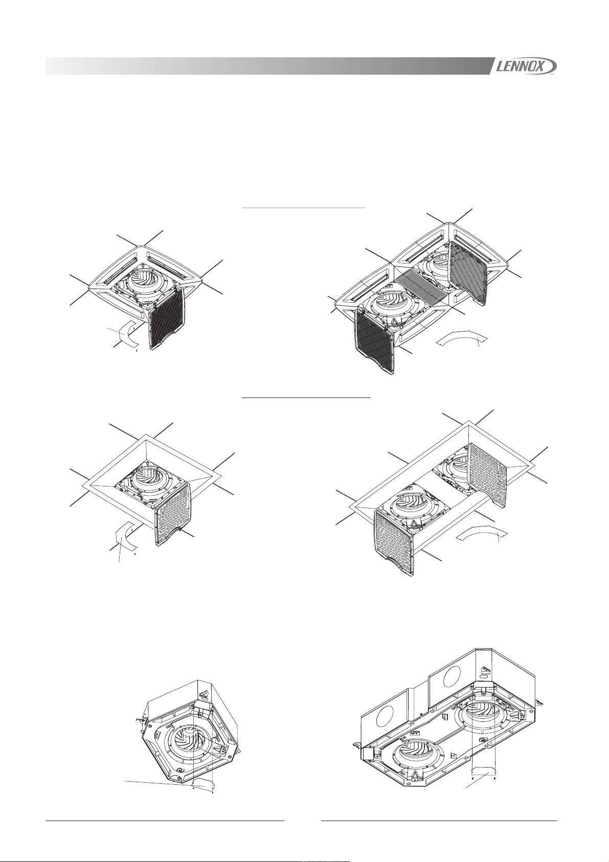
MAINTENANCE
COIL CLEANING
Check the coil and make sure it is not blocked with dust or dirt.
Please clean the coil if it is dirty.
ACCESS TO ELECTRICAL COMPONENTS
Access to terminal plate
The terminal plate can be accessed by removing the air intake grille and unscrewing the terminal cover.
PLASTIC DIFFUSER PANEL
MODEL 600x1200MODEL 600x600
TERMINAL
PLATE
COVER
TERMINAL
PLATE
COVER
METALLIC DIFFUSER PANEL
MODEL 600x1200MODEL 600x600
TERMINAL PLATE
COVER
Access to electrical panel
To gain access to the electrical panel follow these instructions:
1.- Disassemble the diffuser panel by removing the screws that attaches it to the unit.
2.- Remove the cover of the electrical panel, where is the PCB, (depending on version).
3.- The PCB can be checked or replaced, by loosening the screws that hold it.
MODEL 600x1200MODEL 600x600
TERMINAL PLATE
COVER
ELECTRICAL PANEL
COVER
ELECTRICAL PANEL
COVER
19
Page 21

MAINTENANCE
WARNING: Electric shock hazard can cause injury or death. Before attempting to perform any service or maintenance
on the unit, turn OFF the electrical power, and check that the fan has stopped.
ACCESS TO INTERNAL COMPONENTS
When checking or replacing any internal component of the unit, e.g. coil, fan motor, condensate pump, float switch, the drip
tray and volute must be removed.
DISASSEMBLING DRIP TRAY
Remove the air intake grille and filter.
Disassemble the diffuser panel by removing the screws that attach it to the unit.
Detach the volute/s by removing the screws, and the electrical panel cover/s.
The drip tray can be taken apart by removing its screws, as shown in the figure.
MODEL
1
600x600
4
3
Volute
AIR DISTRIBUTION
2
Drip tray
1
Coil
2
Fan motor
3
Condensate pump
4
Float switch (in option)
MODEL
600x1200
Volute
2
1
4
Louvres change position to distribute air according to heating or cooling
operation (only for plastic diffuser).
In cooling operation the louvres are positioned to distribute air
outwards from the discharge, which allow airflow close to the ceiling.
3
Drip tray
2
1
1
Louvre position for correct air flow in heating
mode.
2
Louvre position for correct air flow in cooling
mode.
FAULT ANALYSIS
PROBLEM ACTION
Check power is available at unit.
1.- Unit not operating.
2.- Indoor unit fan running too
fast without apparent
speed change.
3.- Condensate overflowing.
Check wiring.
Check remote control is functioning and set properly (if any).
Check the indoor unit filter is clean.
Check wiring.
If problem persists then motor may be faulty.
Check drip tray for blockage, and condensate drains away.
Check unit is level.
Check condensate pump is working.
Check service drain pipework.
In heating mode the louvres are repositioned to blow air in a
downward direction. The air should flow towards to the floor to prevent
layers or stationary hot air forming in the upper part of the room.
When the electro-mechanical thermostat is used, the louvres movement
is manual, louvres should be positioned manually.
20
Page 22

NOTES
21
Page 23

NOTES
22
Page 24

www.lennoxeurope.com
BELGIUM,
LUXEMBOURG :
CZECH REPUBLIC :
FRANCE :
GERMANY :
IRELAND :
NETHERLANDS :
POLAND :
LENNOX BENELUX N.V./S.A.
www.lennoxbelgium.com
LENNOX JANKA a.s.
www.janka.cz
LENNOX FRANCE
www.lennoxfrance.com
LENNOX DEUTSCHLAND GmbH
www.lennoxdeutschland.com
LENNOX IRELAND
www.lennoxireland.com
LENNOX BENELUX B.V.
www.lennoxbenelux.com
LENNOX POLSKA Sp. z o. o.
www.lennoxpolska.com
PORTUGAL :
RUSSIA :
SLOVAKIA :
SPAIN :
UKRAINE :
UNITED KINGDOM :
OTHER COUNTRIES :
LENNOX PORTUGAL Lda.
www.lennoxportugal.com
LENNOX DISTRIBUTION MOSCOW
www.lennoxrussia.com
LENNOX SLOVENSKO s.r.o.
www.lennoxdistribution.com
LENNOX REFAC S.A.
www.lennox-refac.com
LENNOX DISTRIBUTION KIEV
www.lennoxrussia.com
LENNOX UK
www.lennoxuk.com
LENNOX DISTRIBUTION
www.lennoxdistribution.com
COD: MSL102E-0105 03-2005
Due to Lennox's ongoing commitment to quality, Specifications, Ratings and Dimensions subject to change without notice and without incurring liability.
Improper installation, adjustment, alteration, service or maintenance can cause property damage or personal injury.
Installation and service must be performed by a qualified installer and servicing agency.
 Loading...