

Lennox Compactair LVHA 24E, Compactair LVHA 38E, Compactair LVHA 28E, Compactair LVHA 32E, Compactair LVHK 22E Installation, Operation & Maintenance Manual
...Page 1
COMPACTAIR
LVCK / LVHK
English/03-2005
INSTALLATION
OPERATION &
MAINTENANCE MANUAL
Page 2

1
WARNING: Read this manual before installation, reparation o maintenance works.
1.1.- PHYSICAL DATA
1.2.- ELECTRICAL DATA
1.3.- FAN PERFORMANCES
1.4.- OPERATING LIMITS
1.5.- UNIT DIMENSIONS
1.6.- AVAILABLE OPTIONS
PAGE
PAGE
PAGE
PAGE
4-5
6
7-10
11
12-17
18-33
34
34
35-36
37
38
39
39
40-43
44
45
46
47
48
PAGE 3
2.1.- INSTALLATION GUIDELINES
2.2.- UNIT INSTALLATION
2.3.- OPTIONAL TASK PRIOR TO UNIT INSTALLATION:
CHANGING THE POSITION OF DISCHARGE AND AIR INTAKE
2.4.- OPTIONAL TASK PRIOR TO UNIT INSTALLATION:
FLOW REGULATION IN THE FANS
2.5.- UNIT LOCATION
2.6.- INSTALLATION CLEARANCES
2.7.- DRAINS
2.8.- ELECTRICAL CONNECTIONS
POINTS TO KEEP IN MIND
PAGE 2
3.1.- PRELIMINARY CHECKS
3.2.- STEPS TO FOLLOW FOR COMMISSIONING THE UNIT
4.1.- PREVENTIVE MAINTENANCE
4.2.- CORRECTIVE MAINTENANCE
4.3.- FAILURE DIAGNOSIS
4.- MAINTENANCE
DATA PAGE FOR UNIT COMMISSIONING
2.- INSTALLATION
3.- COMMISSIONING AND OPERATION
1.- GENERAL CHARACTERISTICS
TABLE OF CONTENTS
Lennox have been providing environmental solutions since 1895, our range of COMPACTAIR continues to meet the standards
that have made LENNOX a household name. Flexible design solutions to meet YOUR needs and uncompromising attention
to detail. Engineered to last, simple to maintain and Quality that comes as standard. Information on local contacts at
www.lennoxeurope.com.
All the technical and technological information contained in this manual, including any drawing and technical descriptions
provided by us, remain the property of Lennox and must not be utilised (except in the operation of this product), reproduced,
issued to or made available to third parties without the prior written agreement of Lennox.
Page 3
2
Risk of injury with
rotating objects
Low
temperatures
High
temperatures
Risk of injury with
moving objects
Electrical
voltage
Abrasive
surfaces
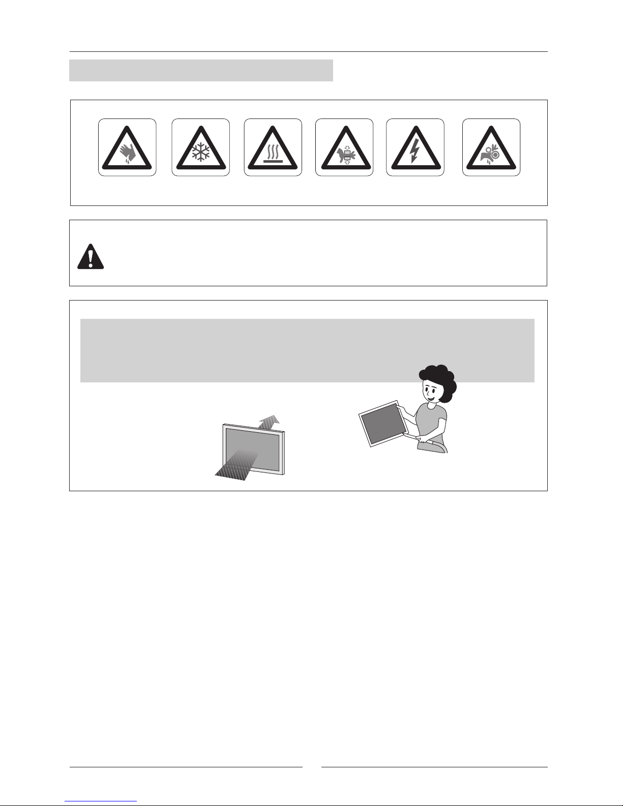
FILTER CLEANING
Check the air filter and make
sure it is not blocked with dust
or dirt.
If the filter is dirty, wash it in a bowl with neutral
soap and water, drying it in the shade before
inserting it in the unit.
All technical data contained in these operating instructions including the diagrams and technical description remains the property
of Lennox and may not be used (except for the purpose of familiarizing the user with the equipment), reproduced, photocopied,
transferred or transmitted to third parties without prior written authorization from Lennox .
The data published in the operating instructions is based on the latest information available. We reserve the right to make
modifications without notice.
We reserve the right to modify our products without notice without obligation to modify previously supplied goods.
These operating instructions contain useful and important information for the smooth operation and maintenance of your
equipment.
The instructions also include guidelines on how to avoid accidents and serious damage before commissioning the equipment
and during its operation and how to ensure smooth and fault-free operation. Read the operating instructions carefully before
starting the equipment, familiarize yourself with the equipment and handling of the installation and carefully follow the instructions.
It is very important to be properly trained in handling the equipment. These operating instructions must be kept in a safe place
near the equipment.
Like most equipment, the unit requires regular maintenance. This section concerns the maintenance personnel and management.
If you have any queries or would like to receive further information on any aspect relating to your equipment, do not hesitate
to contact us.
The air filter cleaning operations do not
require technical service; however when
an electrical or mechanical operation
is required call an Engineer.
Electric shock hazard can cause injury
or death. Before attempting to perform
any service or maintenance on the
unit, turn OFF the electrical power,
and check that the fan has stopped.
Standard Guidelines to Lennox equipment
POINTS TO KEEP IN MIND
DANGER AND WARNING SIGNS
Make sure to open the power off switch before to install, repair or make maintenance works in the unit, in order to
prevent serious electrical injuries.
To install the unit, keep in mind local and national legislation.
ELECTRICAL CONNECTIONS
ATTENTION - WARNING
Page 4
3
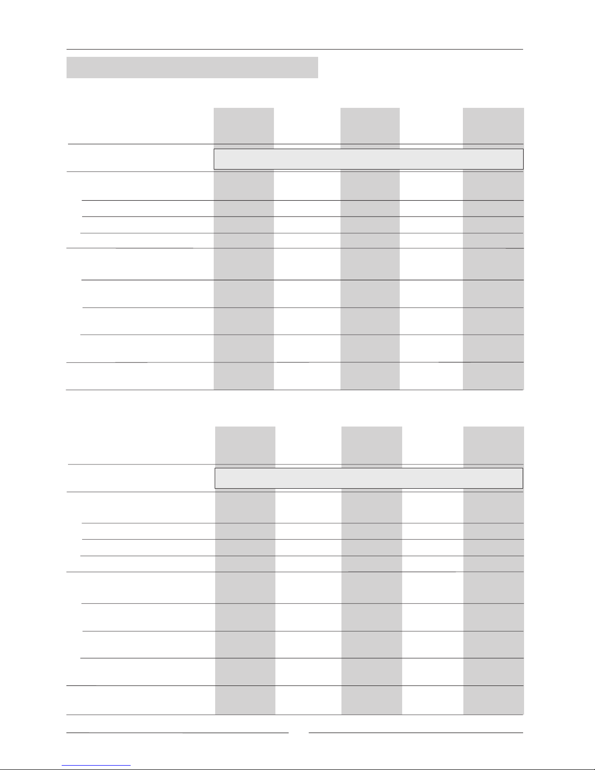
DATA INPUT:
COLD CYCLE
HEATING CYCLE
ºC
ºC
ºC
ºC
Fan outdoor section 1
Fan outdoor section 1
circuit 1
circuit 2
circuit 1
circuit 2
ºC
1
ºC
2
ºC
1
ºC
2
ºC
1
ºC
2
ºC
1
ºC
2
circuit 1
circuit 2
circuit 1
circuit 2
Fan outdoor section 2
Fan outdoor section 2
Compressor 1 Compressor 2 Compressor 1 Compressor 2
Air Intake Temperature, Indoor Coil:
Air Output Temperature, Indoor Coil:
High Pressure:
Low Pressure:
Options Installed:
High Pressure:
Low Pressure:
Comments:
ELECTRIC POWER CONSUMPTION
Fan indoor section
(Amps)
Air Intake Temperature, Outdoor Coil:
Air Output Temperature, Outdoor Coil:
Air Intake Temperature, Indoor Coil:
Air Output Temperature, Indoor Coil:
INSTALLATION ADDRESS:
INSTALLER:
INSTALLER TEL.:
CHECKS:
SUPPLY VOLTAGE:
DATE OF COMMISSIONING:
INSTALLER ADDRESS:
RATED VOLTAGE OF THE UNIT:
YES NO
GENERAL POWER SUPPLY CONNECTION
CONTROL PANEL CONNECTION
COMPRESSOR OIL LEVEL INDICATOR
UNIT ON SHOCK ABSORBERS
DRAINAGE WITH TRAP
CLEAN INTERIOR AIR FILTER
CONTROL PANEL IDENTIFICATION CODE
Air Intake Temperature, Outdoor Coil:
Air Output Temperature, Outdoor Coil:
Fan indoor section
DATE PAGE FOR UNIT COMMISSIONING
UNIT:
SERIAL Nr.:
Page 5

4
kW
Kg
kW
kW
kW
Pa
m /h.
3
(1)
m /h.
3
Pa
m /h.
3
m /h.
3
Kg
gr.
gr.
(*)
(**)
(*)
(**)
LVCK
LVHK
(1)
LVCK 22E
LVHK 22E
LVCK 24E
LVHK 24E
LVCK 28E
LVHK 28E
LVCK 32E
LVHK 32E
LVCK 38E
LVHK 38E
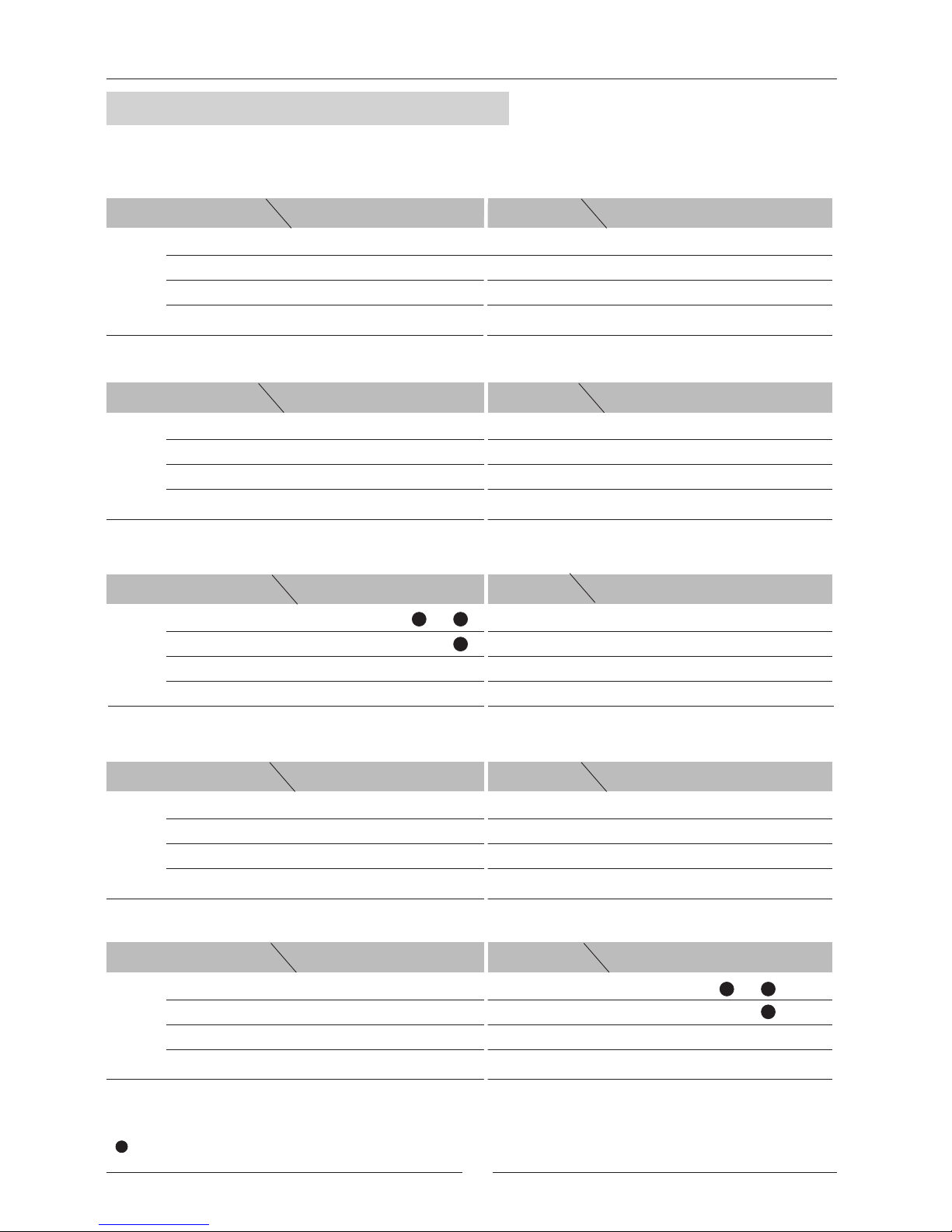
LVHA 22E LVHA 24E LVHA 28E LVHA 32E LVHA 38E
Cooling capacity
COMPRESSOR
FAN OUTDOOR SECTION
NET WEIGHT
Heating capacity
Refrigerant charge R-22
Refrigerant charge
R-407C
Maximum air flow
Maximum available pressure
Minimum air flow
FAN INDOOR SECTION
(1) With admissible minimum air flow.
UNIT MODELS
UNIT MODELS
Cooling only units
Heat pump units
UNIT MODELS
Maximum air flow
Maximum available pressure
Minimum air flow
1 / Scroll
22E
19,50
20,20
19,20
20,40
5100
5700
5600
170
7550
3500
205
4700
310
6000
1 / Scroll
24E
22,00
22,50
21,50
22,70
5600
6250
5600
160
7350
3900
195
5100
370
6550
1 / Scroll
28E
26,50
27,00
26,00
27,30
6700
7400
5600
140
7100
4500
250
5850
385
7500
1 / Scroll
32E
28,70
30,30
28,10
30,90
7600
8450
6500
300
8000
4750
220
6000
390
8900
36,50
1 / Scroll
36,90
38E
35,80
37,60
10500
9500
9000
300
11000
5800
240
7300
505
10900
315 375 390 395 510
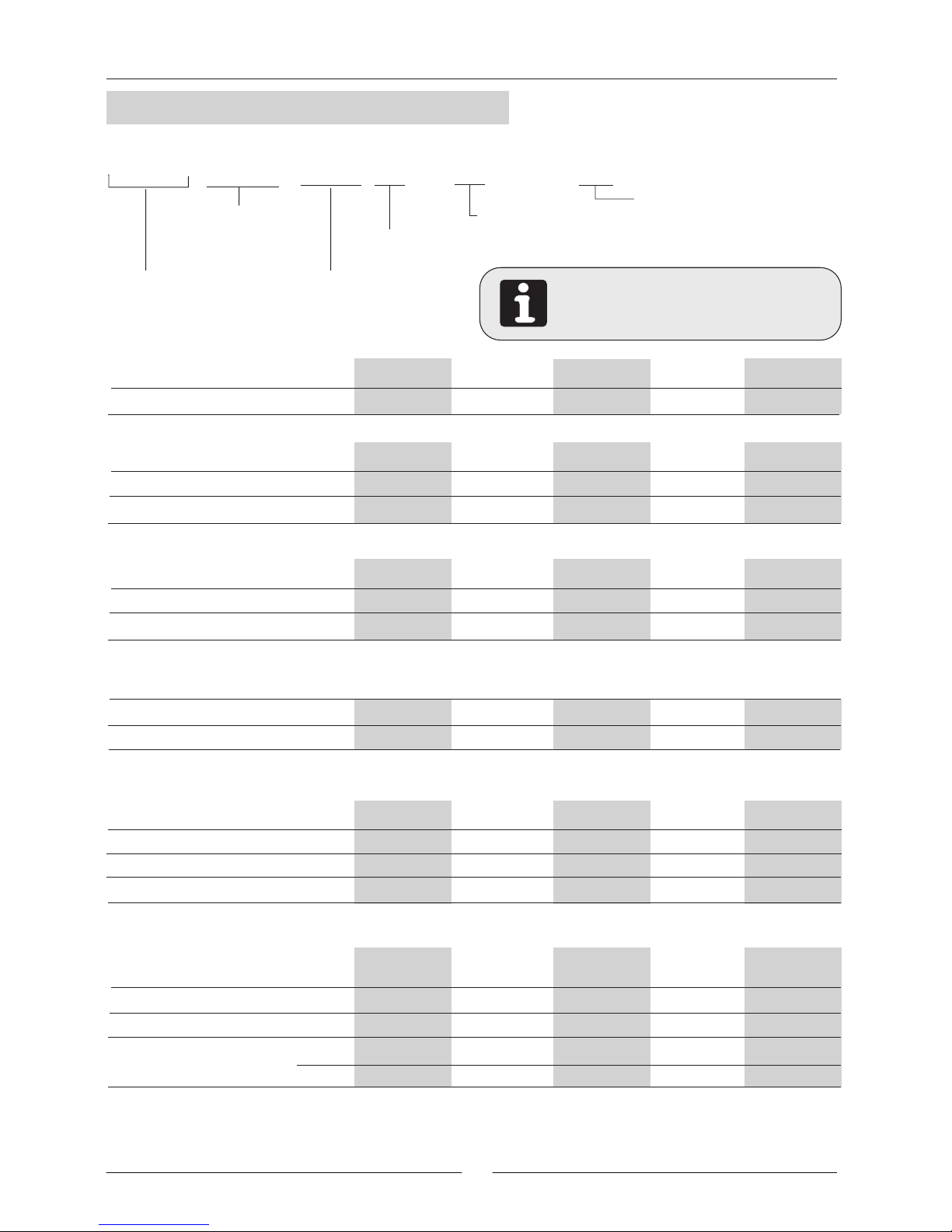
LVHA: Heat pump unit R-22
LVCK: Cooling only unit R-407C
LVHK: Heat pump unit R-407C
Type of Refrigerant
A: R-22
K: R-407C
LV C K 24
Type of unit
Vertical compact
COMPACTAIR
VFC
VFC: Voltage free contact
unit version.
------: Standard unit version.
E
E: One circuit
D: Two circuits
DB.- Dry bulb temperature
WB.- Wet bulb temperature
(*) Air intake temperature in the indoor exchanger: 27°C DB/19 °C WB
(*) Air intake temperature in the outdoor exchanger: 35 ºC DB
(**) Air intake temperature in the indoor exchanger: 20°C DB / 12 ºC WB
(**) Air intake temperature in the outdoor exchanger: 7°C DB / 6 ºC WB
Application
C: Cooling only
H: Heat pump
Approximately cooling
capacity in kW
1.1.- PHYSICAL DATA
1.- GENERAL CHARACTERISTICS
Nr. / Type
Cooling capacity
Heating capacity
Page 6
5
kW
Kg
kW
kW
kW
Pa
m /h.
3
(1)
m /h.
3
Pa
m /h.
3
m /h.
3
Kg
gr.
gr.
(*)
(**)
(*)
(**)
LVCK
LVHK
(1)
LVHA 44D LVHA 48D LVHA 56D LVHA 64D LVHA 76D
Cooling capacity
FAN OUTDOOR SECTION
NET WEIGHT
Heating capacity
Cooling capacity
Heating capacity
Refrigerant charge R-22
Refrigerant charge
R-407C
Maximum available pressure
Minimum air flow
FAN INDOOR SECTION
(1) With admissible minimum air flow.
UNIT MODELS
UNIT MODELS
Cooling only units
Heat pump units
UNIT MODELS
Maximum available pressure
Minimum air flow
Maximum air flow
Maximum air flow
2 / Scroll
44D
39,00
40,40
38,40
40,80
10200
11400
11200
170
15100
7000
205
9400
620
12000
2 / Scroll
48D
44,00
45,00
43,00
45,40
11200
12500
11200
160
14700
7800
195
10200
740
13100
2 / Scroll
56D
53,00
54,00
52,00
54,60
13400
14800
11200
140
14200
9000
250
11700
780
15000
2 / Scroll
64D
57,40
60,60
56,20
61,80
15200
16900
13000
300
16000
9500
220
12000
785
17800
73,00
2 / Scroll
73,80
76D
71,60
75,20
21000
19000
18000
300
22000
11600
240
14600
935
21800
LVCK 44D
LVHK 44D
LVCK 48D
LVHK 48D
LVCK 56D
LVHK 56D
LVCK 64D
LVHK 64D
LVCK 76D
LVHK 76D
630 750 790 795 945
LV C K
VFC
VFC: Voltage free contact
unit version.
------: Standard unit version.
24
E
Type of Refrigerant
A: R-22
K: R-407C
Type of unit
Vertical compact
COMPACTAIR
LVHA: Heat pump unit R-22
LVCK: Cooling only unit R-407C
LVHK: Heat pump unit R-407C
DB.- Dry bulb temperature
WB.- Wet bulb temperature
(*) Air intake temperature in the indoor exchanger: 27°C DB/19 °C WB
(*) Air intake temperature in the outdoor exchanger: 35 ºC DB
(**) Air intake temperature in the indoor exchanger: 20°C DB / 12 ºC WB
(**) Air intake temperature in the outdoor exchanger: 7°C DB / 6 ºC WB
Application
C: Cooling only
H: Heat pump
Approximately cooling
capacity in kW
E: One circuit
D: Two circuits
1.- GENERAL CHARACTERISTICS
1.1.- PHYSICAL DATA
COMPRESSOR
Nr. / Type
Page 7
6
V/f (50 Hz)
kW
kW
kW
kW
A
A
A
A
A
V/f (50 Hz)
kW
kW
kW
kW
A
A
A
A
A
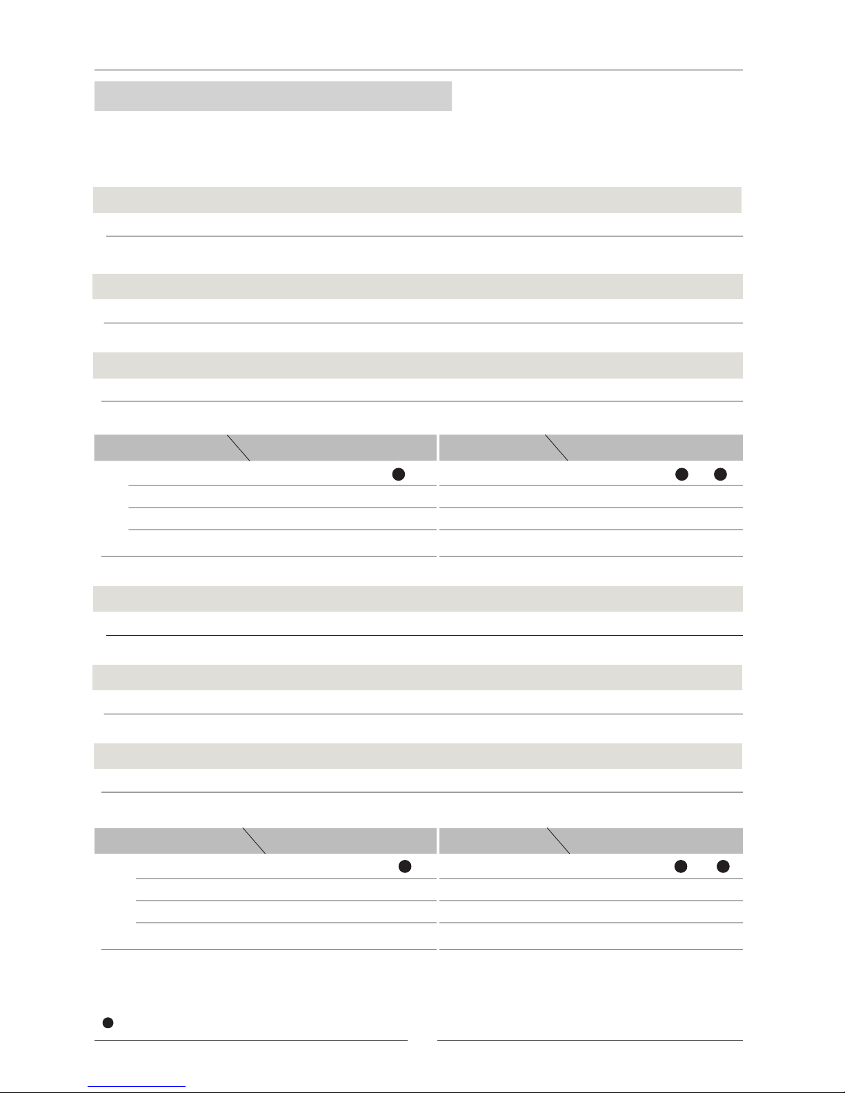
1.2.- ELECTRICAL DATA
Total power
Voltage
Maximum current
Maximum absorbed power
Total power
Voltage
Maximum current
Total current
Start up current
Maximum absorbed power
Total Current
Start up current
UNIT MODELS
Fan outdoor section
Fan outdoor section
Compressor
Fan outdoor section
Compressor
Compressor
Compressor
Fan outdoor section
Fan indoor section
UNIT MODELS
Fan indoor section
Fan indoor section
Fan indoor section
230V-400V/ 3Ph
33,1/19,1
188,7/107,2
4,3/2,5
6,4/3,7
22,4/12,9
1,3
2,2
7,6
11,1
35,0/20,2
176,7/105,2
24,3/14
1,4
2,2
8,62
12,2
4,3/2,5
6,4/3,7
6,2/3,6
6,4/3,7
28,5/16,4
1,5
2,2
11,15
14,9
41,1/23,7
222,6/130,3
6,2/3,6
8,8/5,1
1,8
2,5
12,9
17,2
51,5/29,7
239,0/135,7
36,5/21
2
2,8
15,55
20,4
64,8/36,4
297,7/168,8
6,2/3,6
12,5/7,2
46,1/25,6
LVCK 22E
LVHK 22E
LVHA 22E
LVCK 24E
LVHK 24E
LVHA 24E
LVCK 28E
LVHK 28E
LVHA 28E
LVCK 32E
LVHK 32E
LVHA 32E
LVCK 38E
LVHK 38E
LVHA 38E
230V-400V/ 3Ph
66,4/38,3
222,0/126,4
8,8/5,1
12,8/7,4
44,8/25,8
2,6
4,4
15,2
22,2
70,2/40,5
211,9/125,5
48,6/28
2,8
4,4
17,24
24,4
8,8/5,1
12,8/7,4
12,5/7,2
12,8/7,4
57/32,8
3
4,4
22,3
29,7
82,3/47,4
263,8/154,0
12,5/7,2
17,6/10,2
3,6
5
25,8
34,4
103,1/59,4
290,6/165,4
73/42
4
5,6
31,1
40,7
129,6/72,8
362,5/205,2
12,5/7,2
24,9/14,4
92,2/51,2
LVCK 44D
LVHK 44D
LVHA 44D
LVCK 48D
LVHK 48D
LVHA 48D
LVCK 56D
LVHK 56D
LVHA 56D
LVCK 64D
LVHK 64D
LVHA 64D
LVCK 76D
LVHK 76D
LVHA 76D
R-407C
R-22
1.- GENERAL CHARACTERISTICS
Page 8
7
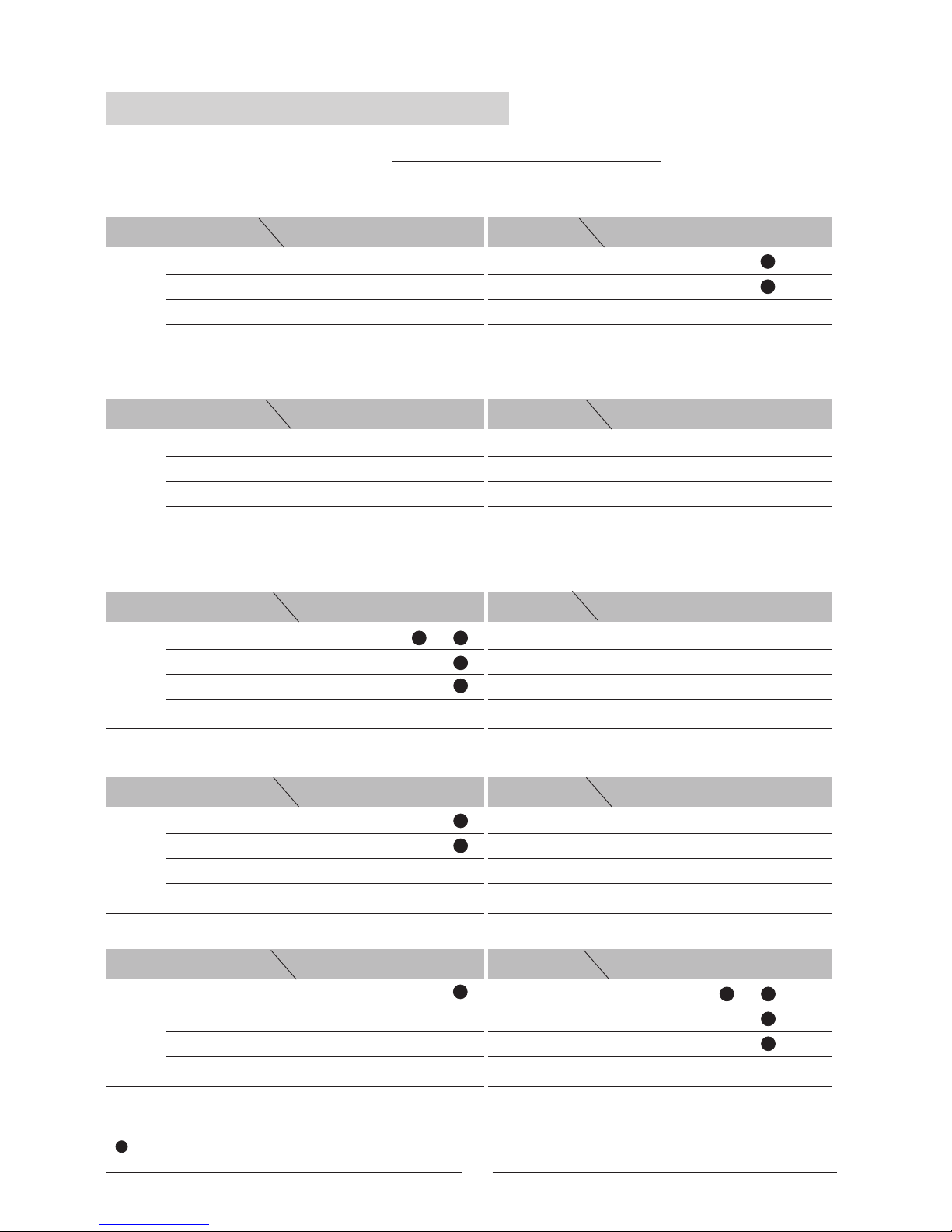
1.3.- STANDARD INDOOR FAN PERFORMANCES
PULLEY
POSITION
22E
3500 3900 4300 4700
24E
3900 4300 4700 5100
28E
4500 4950 5400 5850
32E
5250 5750 60004750
38E
48D
56D
7800 8600 9400 10200
9000 9900
10800
11700
44D
7000 7800 8600 9400
5800 6400 7000 7300
64D
76D
9500 10500 11500 12000
11600 12800 14000 14600
PULLEY CLOSED
1 TURN
2 TURNS
3 TURNS
AIR FLOW
PULLEY
POSITION
PULLEY CLOSED
1 TURN
2 TURNS
3 TURNS
AIR FLOW
PULLEY
POSITION
PULLEY CLOSED
1 TURN
2 TURNS
3 TURNS
AIR FLOW
PULLEY
POSITION
PULLEY CLOSED
1 TURN
2 TURNS
3 TURNS
AIR FLOW
PULLEY
POSITION
PULLEY CLOSED
1 TURN
2 TURNS
3 TURNS
AIR FLOW
205*
165*
195*
150*
165*
125*
130* 115* 90*
105* 80* 60*
55*
20*
90*
195*
150*
165*
125*
130*
90*
115* 90* 55*
80* 60* 20*
15*
___
50*
250*
190*
200*
145*
95*
40*
145* 100* 0*
105* 55*
___
___
___
___
220*
165*
175*
115*
115*
50*
125* 65* 0*
80* 25*
___
___
___
1010
955
900
845
1010
955
900
845
890
840
790
740
890
840
790
740
130*
85*
30*
0*
70*
195*
150*
165*
125*
130*
90*
890
840
790
740
115* 90* 55*
80* 60* 20*
15*
___
50*
250*
190*
200*
145*
95*
40*
145* 100* 0*
105* 55* ___
___
___
85*
1010
955
900
845
30*
___
205*
165*
195*
150*
165*
125*
130* 115* 90*
105* 80* 60*
55*
20*
90*
890
840
790
740
130*
240*
190*
200*
150* 100*
1010
900
845
150* 110* 65*
105* 60* 15*
40*
0*
955
240*
190*
200*
150* 100*
150* 110* 65*
105* 60* 15*
40*
0*
1010
955
900
845
80* 25* ___
___
125* 65* 0* ___
165*
115* 50*
220* 175* 115*
0*
70*
1140
1070
995
920
(*)
( )
AVAILABLE STATIC PRESSURE Pa.
WRONG STATUS ON ACCOUNT OF MOTOR POWER LIMIT.
NOTE: The unit leaves factory with pulley two
turns opened.
1.- GENERAL CHARACTERISTICS
M3/H
R.P.M.
M3/H
R.P.M.
M3/H
R.P.M.
M3/H
R.P.M.
M3/H
R.P.M.
M3/H
R.P.M.
M3/H
R.P.M.
M3/H
R.P.M.
M3/H
R.P.M.
M3/H
R.P.M.
Page 9
8
1.3.- STANDARD OUTDOOR FAN PERFORMANCES
22E
24E
28E
32E
38E
5600 6325
7350
5600 6325
7550
AVAILABLE STATIC PRESSURE Pa.
9000 9600 10300 11000
7050
6800
5600 6125
7100
6650
6500 7000 7500 8000
13000
14000
15000
16000
18000
19200
20600
22000
44D
64D
76D
AIR FLOW M3/H
AIR FLOW M3/H
AIR FLOW M3/H
AVAILABLE STATIC PRESSURE Pa.
AVAILABLE STATIC PRESSURE Pa.
AVAILABLE STATIC PRESSURE Pa.
AIR FLOW M3/H
AIR FLOW M3/H
AIR FLOW M3/H
AVAILABLE STATIC PRESSURE Pa.
AVAILABLE STATIC PRESSURE Pa.
11.200 12.650 15.10014.100
48D
11.200 12.650
14.700
13.600
56D
11.200 12.250
14.200
13.300
PULLEY
POSITION
PULLEY CLOSED
1 TURN
2 TURNS
3 TURNS
AIR FLOW
PULLEY
POSITION
PULLEY CLOSED
1 TURN
2 TURNS
3 TURNS
AIR FLOW
140 90 50 0
160 110 50 0
170 120 50 0
1000
300*
250*
270*
200*
160* 120*
90* 40*
930
870
800
165*
70*
0*
25*
___
110*
1140
300*
230*
275*
200*
175* 140*
115* 75*
1070
995
920
225*
140*
75*
20*
25*
___
1140
1070
995
920
300*
230*
275*
200*
225*
140*
175*
140*
75*
115*
75*
20*
25*
___
1000
930
870
800
300*
250*
270*
200*
165*
160*
120*
70*
90*
40*
0*
110*
25*
___
170 120 50 0
160 110 50 0
140 90 50 0
85*
85*
( )
NOTE: The unit leaves factory with pulley two
turns opened.
(*)
AVAILABLE STATIC PRESSURE Pa.
WRONG STATUS ON ACCOUNT OF MOTOR POWER LIMIT.
1.- GENERAL CHARACTERISTICS
M3/H
R.P.M.
M3/H
R.P.M.
M3/H
R.P.M.
M3/H
R.P.M.
Page 10
9
1.3.- INDOOR FAN PERFORMANCES WITH KIT HIGH STATIC PRESSURE TO 400Pa (OPTION)
38E
22E
3500 3900 4300 4700
24E
3900 4300 4700 5100
28E
4500 4950 5400 5850
32E
5250 5750 6000
48D
56D
7800 8600 9400 10200
9000 9900
10800
11700
44D
7000 7800 8600 9400
4750
5800 6400 7000 7300
64D
76D
9500 10500 11500 12000
11600 12800 14000 14600
PULLEY
POSITION
PULLEY CLOSED
1 TURN
2 TURNS
3 TURNS
AIR FLOW
PULLEY
POSITION
PULLEY CLOSED
1 TURN
2 TURNS
3 TURNS
PULLEY
POSITION
PULLEY CLOSED
1 TURN
2 TURNS
3 TURNS
AIR FLOW
AIR FLOW
PULLEY
POSITION
PULLEY CLOSED
1 TURN
2 TURNS
3 TURNS
AIR FLOW
PULLEY
POSITION
PULLEY CLOSED
1 TURN
2 TURNS
3 TURNS
AIR FLOW
420*
360*
405*
340*
385*
315*
290* 275* 250*
240*
215* 190*
205*
160*
290*
405*
340*
385*
315*
360*
290*
275* 250* 205*
215* 190* 160*
195*
130*
410*
340*
390*
305*
320*
240*
275* 240* 165*
215* 175* 100*
130*
60*
210*
400*
330*
365*
290*
300*
220*
265* 225* 145*
205* 160* 80*
110*
40*
1200
1125
1050
970
1200
1125
1050
970
1140
1070
995
920
1140
1070
995
920
360*
290*
405*
340*
385*
315*
360*
290*
1140
1070
995
920
275* 250* 205*
215* 190* 160*
195*
130*
410*
340*
390*
305*
320*
240*
275* 240* 165*
215* 175* 100*
130*
60*
1200
1125
1050
970
290*
210*
420*
360*
405*
340*
385*
315*
290* 275* 250*
240* 215* 190*
205*
160*
290*
1140
1070
995
920
360*
270*
190*
400*
320*
385*
305* 260*
1200
1050
970
270* 235* 180*
220* 185* 110* 95*
1125
400*
320*
385*
305* 260*
270* 235* 180*
220* 185* 110*
95*
1200
1125
1050
970
1200
1125
1050
970
205* 160* 80*
40*
265* 225* 145* 110*
330* 290* 220*
400* 365* 300*
190*
(*)
( )
NOTE: The unit leaves factory with pulley two
turns opened.
AVAILABLE STATIC PRESSURE Pa.
WRONG STATUS ON ACCOUNT OF MOTOR POWER LIMIT.
1.- GENERAL CHARACTERISTICS
M3/H
R.P.M.
M3/H
R.P.M.
M3/H
R.P.M.
M3/H
R.P.M.
M3/H
R.P.M.
M3/H
R.P.M.
M3/H
R.P.M.
M3/H
R.P.M.
M3/H
R.P.M.
M3/H
R.P.M.
Page 11
10
1.3.- OUTDOOR FAN PERFORMANCES WITH KIT HIGH STATIC PRESSURE TO 350Pa (OPTION)
22E
24E
5600 6325 6800 7350
5600 6325 7050 7550
5600
6125
6650
7100
11200 12650
14100
15100
28E
44D
11200
12650
13600
14700
11200 12250
13300
14200
48D
56D
PULLEY
POSITION
PULLEY CLOSED
1 TURN
2 TURNS
3 TURNS
AIR FLOW
PULLEY
POSITION
PULLEY CLOSED
1 TURN
2 TURNS
3 TURNS
AIR FLOW
PULLEY
POSITION
PULLEY CLOSED
1 TURN
2 TURNS
3 TURNS
AIR FLOW
1140
365*
290*
325*
250*
240* 190*
185* 140*
1070
995
920
290*
210*
165*
105*
135*
70*
195*
1140
365*
290*
330*
255*
240* 195*
185* 145*
1070
995
920
290*
210*
165*
105*
135*
70*
1140
1070
995
920
365*
290*
325*
250*
290*
210*
240*
190*
165*
185*
140*
105*
135*
70*
1140
1070
995
920
365*
290*
330*
255*
210*
240*
195*
165*
185*
145*
105*
135*
70*
1140
1070
995
920
365*
290*
330*
255*
290*
210*
240*
195*
165*
185*
145*
105*
135*
1140
1070
995
920
365*
290*
330*
255*
290*
210*
240*
195*
165*
185*
145*
105*
195*
135*
70*
70*
195*
270*
195*
(*)
( )
NOTE: The unit leaves factory with pulley two
turns opened.
AVAILABLE STATIC PRESSURE Pa.
WRONG STATUS ON ACCOUNT OF MOTOR POWER LIMIT.
1.- GENERAL CHARACTERISTICS
M3/H
R.P.M.
M3/H
R.P.M.
M3/H
R.P.M.
M3/H
R.P.M.
M3/H
R.P.M.
M3/H
R.P.M.
Page 12
+19º C STANDARD UNIT
0ºC WITH OPTIONAL CPC ON/OFF
-10ºC (*)
INDOOR
TEMPERATURE
OUTDOOR
TEMPERATURE
COOLING CYCLE
OPERATION
MAXIMUM TEMPERATURES MINIMUM TEMPERATURES
MAXIMUM TEMPERATURES MINIMUM TEMPERATURES
INDOOR
TEMPERATURE
OUTDOOR
TEMPERATURE
INDOOR
TEMPERATURE
OUTDOOR
TEMPERATURE
COOLING CYCLE
OPERATION
HEATING CYCLE
OPERATION
32ºC DB / 23ºC WB
DEPENDING ON MODEL
(TABLE 1)
+19ºC STANDARD UNIT
0ºC WITH OPTIONAL CPC ON/OFF
-10ºC (*)
21ºC DB / 15ºC WB
32ºC DB / 23ºC WB
21ºC DB / 15ºC WB
27ºC DB
15ºC DB
24ºC DB / 18ºC WB
-10ºC DB / -11ºC WB
DEPENDING ON MODEL
(TABLE 1)
11
22E
45
43
24E
45
43
28E
43
41
32E
43
40
38E
42
39
44D
45
43
48D
45
43
56D
43
41
64D
43
40
76D
42
39
22E
48
46
24E
48
45
28E
46
44
32E
46
44
38E
45
42
44D
48
46
48D
48
45
56D
46
44
64D
46
44
76D
45
42
(*) With kit hot gas by pass or proportional winter control (options).
(*) With kit hot gas by pass or proportional winter control (options).
1.- GENERAL CHARACTERISTICS
OPERATING LIMITS FOR (HEATING PUMP) UNITS
OPERATING LIMITS FOR (COOLING ONLY) UNITS
1.4.- OPERATING LIMITS
DB.- Dry Bulb Temperature
WB.- Wet Bulb Temperature
TABLE 1-COOLING CYCLE MAXIMUM OUTDOOR OPERATING TEMPERATURES
MODELS
With rated outdoor flow
With minimum outdoor flow
MODELS WITH Refrigerant R-407C
MODELS
With rated outdoor flow
MODELS WITH Refrigerant R-22
With minimum outdoor flow
Page 13
12
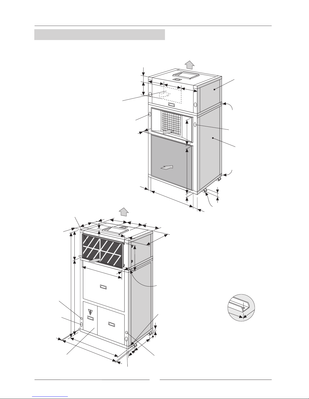
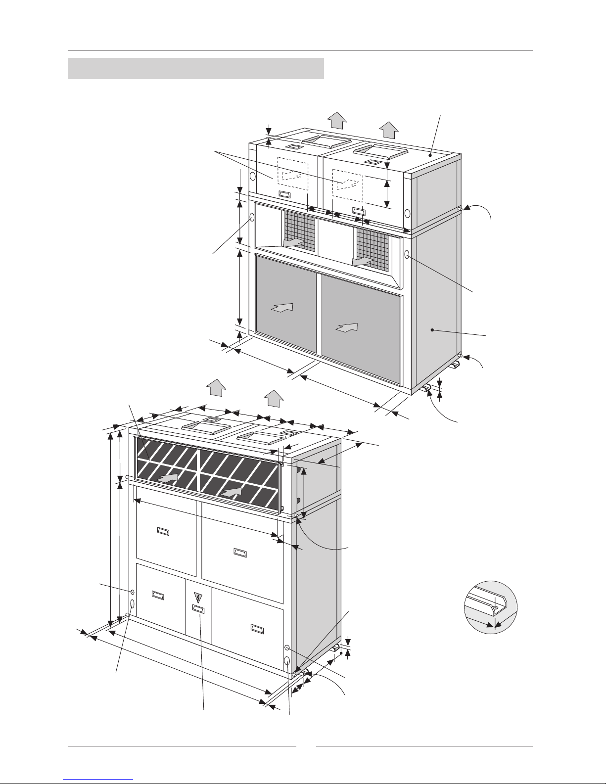
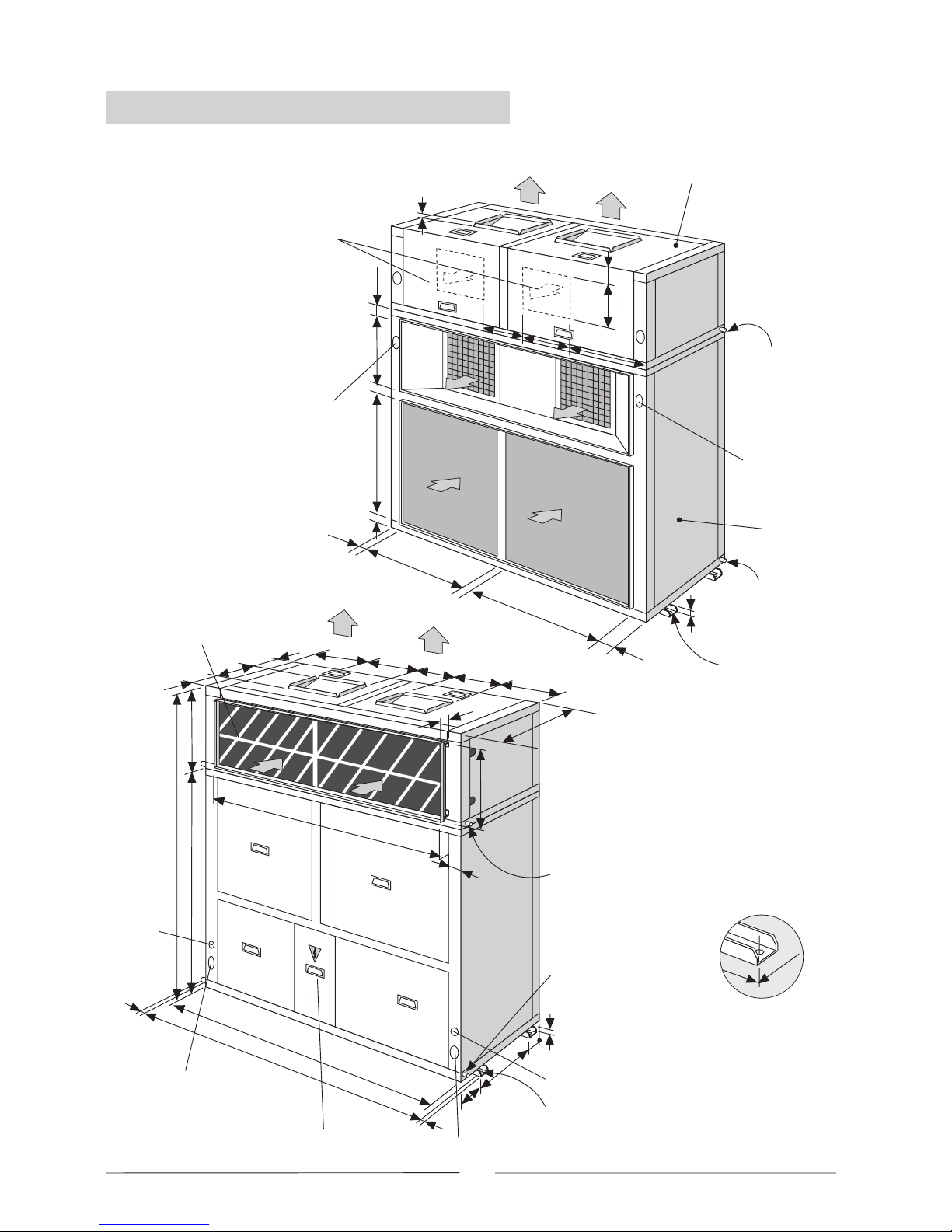
1.5.- UNIT DIMENSIONS MODELS 22E-24E-28E-32E
The dimensions referred to the
center of the drill holes for the
supports.
Power supply
connection
Power supply connection
Control panel connection
Control panel
connection
Electrical box
Air filter
Drainage outside
thread 3/4''
Drainage outside
thread 3/4''
1990
1350
640
1195
100
100
344
316
191
25
450
53
600
105
25
1005
1255
15
15
550
429
215
750
Drainage outside
thread 3/4''
Drainage outside
thread 3/4''
INDOOR
SECTION
OUTDOOR
SECTION
Power supply
Power supply
DISCHARGE
OPTIONAL
Ø 14 (x 4)
20
33
978
99
316
344
191
888
47
25
348
450
429
118
1.- GENERAL CHARACTERISTICS
Page 14
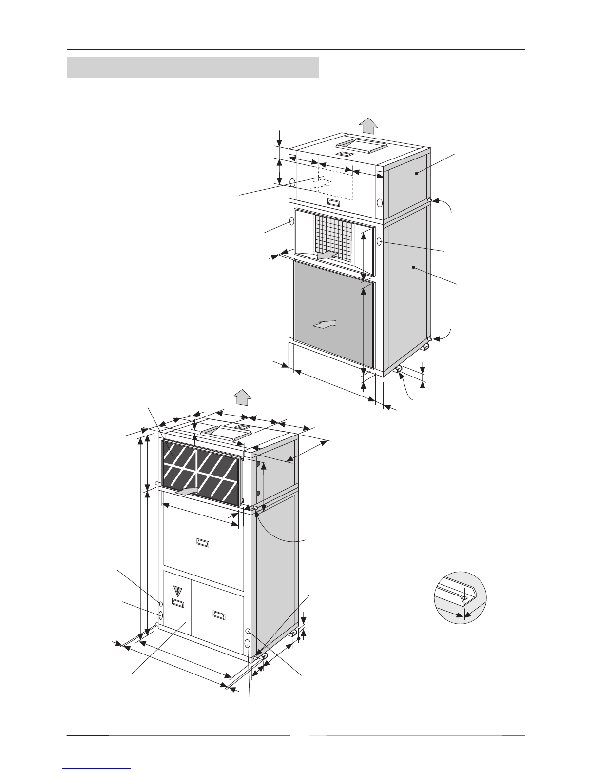
13
The dimensions referred to the
center of the drill holes for the
supports.
Drainage outside
thread 3/4''
Drainage outside
thread 3/4''
INDOOR
SECTION
OUTDOOR
SECTION
Power supply
Power supply
DISCHARGE
OPTIONAL
Ø 14 (x 4)
20
33
1103
99
401
344
191
888
47
25
413
470
449
118
Power supply
connection
Power supply connection
Control panel connection
Control panel
connection
Electrical box
Air filter
Drainage outside
thread 3/4''
Drainage outside
thread 3/4''
2055
1415
640
1320
100
100
344
401
191
25
470
53
600
105
25
1130
1380
15
15
550
449
215
750
1.5.- UNIT DIMENSIONS MODEL 38E
1.- GENERAL CHARACTERISTICS
Page 15
14
1.5.- UNIT DIMENSIONS MODELS 44D-48D-56D-64D
The dimensions referred
to the center of the drill
holes for the supports.
Ø 16 (x 4)
Drainage outside
thread 3/4''
Drainage outside
thread 3/4''
Power supply
INDOOR
SECTION
OUTDOOR
SECTION
Power supply
DISCHARGE
OPTIONAL
34
119
888
56
25
692
348
47
191
978
119
33
978
344
313
240
30
Power supply connection
Control panel connection
Power supply
connection
Control
panel
connection
Electrical box
Air filter
Ø 16 (x 4)
Drainage outside
thread 3/4''
Drainage outside
thread 3/4''
1990
1350
640
2250
100
550
100
344
313
240
313
692
191
30
15
15
2010
120
53
600
2310
692
215
750
1.- GENERAL CHARACTERISTICS
Page 16
15
The dimensions referred
to the center of the drill
holes for the supports.
Ø 16 (x 4)
Drainage outside
thread 3/4''
Drainage outside
thread 3/4''
Power supply
INDOOR
SECTION
OUTDOOR
SECTION
Power supply
DISCHARGE
OPTIONAL
34
119
888
56
25
690
413
47
191
1103
119
33
1103
344
401
318
30
Power supply connection
Control panel connection
Power supply
connection
Control
panel
connection
Electrical box
Air filter
Ø 16 (x 4)
Drainage outside
thread 3/4''
Drainage outside
thread 3/4''
2055
1415
640
2500
100
550
100
344
401
318
401
690
191
30
15
15
2260
120
53
600
2560
690
215
750
1.5.- UNIT DIMENSIONS MODEL 76D
1.- GENERAL CHARACTERISTICS
Page 17

16
1.5 UNIT DIMENSIONS MODELS 44D-48D-56D-64D
WITH KIT 180º TURN FOR INDOOR UNIT (OPTION)
The dimensions referred
to the center of the drill
holes for the supports.
Air filter
Ø 16 (x 4)
Drainage outside
thread 3/4''
Power supply
OUTDOOR
SECTION
Power supply
Drainage outside
thread 3/4''
119
888
56
348
47
978
33
978
640
344
313
240
313
692
191
2010
53
600
120
692
34
750
215
119
30
Power supply connection
Control panel connection
Power supply
connection
Control
panel
connection
Drainage outside
thread 3/4''
INDOOR
SECTION
Ø 16 (x 4)
Drainage outside
thread 3/4''
DISCHARGE
OPTIONAL
Electrical box
1990
1350
2250
100
550
100
30
15
15
2310
25
692
191
344
313
240
1.- GENERAL CHARACTERISTICS
Page 18

17
1.5 UNIT DIMENSIONS MODEL 76D
WITH KIT 180º TURN FOR INDOOR UNIT (OPTION)
The dimensions referred
to the center of the drill
holes for the supports.
Air filter
Ø 16 (x 4)
Drainage outside
thread 3/4''
Power supply
OUTDOOR
SECTION
Power supply
Drainage outside
thread 3/4''
119
888
56
413
47
1103
33
1103
640
344
401
318
401
690
191
2260
53
600
120
690
34
750
215
119
30
Power supply connection
Control panel connection
Power supply
connection
Control
panel
connection
Drainage outside
thread 3/4''
INDOOR
SECTION
Ø 16 (x 4)
Drainage outside
thread 3/4''
DISCHARGE
OPTIONAL
Electrical box
2055
1415
2500
100
550
100
30
15
15
2560
25
690
191
344
401
318
1.- GENERAL CHARACTERISTICS
Page 19

18
1.- GENERAL CHARACTERISTICS
MAIN SWITCH
The main switch is located on the access panel to the electrical box of the outdoor unit.
The main switch is endowed with a clutch gadget, which allows open the panel of the electrical box, when it is on
OFF position.
MODELS LEC (INDOOR UNIT)
22E-24E-28E-32E-38E
MAXIMUM
CURRENT
(A)
230 / III
400/ III
POWER kW
7,5
18,8
10,8
11
27,6
15,9
15
37,7
21,7
44D-48D-56D-64D-76D
15
37,7
21,7
20
50,2
28,9
30
75,3
43,3
WEIGHTS Kg (*)
10 20
22E-24E-28E-32E-38E
(A)
230 / III
400/ III
7,5
18,8
10,8
11
27,6
15,9
15
37,7
21,7
44D-48D-56D-64D-76D
15
37,7
21,7
20
50,2
28,9
11
11
27,6
15,9
11
27,6
15,9
(*) Add to the unit's weight.
(*) Add to the unit's weight.
STAGES
12
10 20
MODELS LEH (INDOOR UNIT)
MAXIMUM
CURRENT
POWER kW
WEIGHTS Kg (*)
STAGES
Check to make sure that the main switch is large enough to handle the current for the unit if electric heaters are
installed.
Security
thermostat
Small case for
contactors and
connections
Situation of the
electrical heater once
installed
Support
ELECTRICAL HEATER
Made of align shielded elements, supplied mounted on the unit as drawing shows.
All the range has three security elements: 2 security thermostat, one automatic other manual reset and an air flow
security pressure switch, which make the electrical heater stops when air flow is not enough.
The electrical heater must be supplied on from the units electrical box.
An small case on the electrical heater protects contactors and electrical connections.
DIRTY FILTER INDICATION
To install on the indoor unit.
It is based on an air flow security pressure switch, which detects the available static pressure through the air filter.
In case the filters are dirties, the detector is activated, showing an alarm, if the fan is ON.
1 1 ó 2
WITH MAIN SWITCH ON. DO NOT REMOVE THE PANEL
ATTENTION!
1.6.- AVAILABLE OPTIONS
Page 20

19
1.- GENERAL CHARACTERISTICS
Situation of the
electrical heater once
installed
Support
Water inlet
Water outlet
PHASE SEQUENCER
The phase sequencer is located in the electrical box in the outdoor section, thus assuring that the unit will not
begin operation while the phase connection of the compressor is not correct. Should this occur, then just switch
two phase connections.
ON/OFF CONDENSATION PRESSURE CONTROL
The condensation pressure control consists of one or two pressure switches, which starts and stops the outdoor
fan, regulating the condensation temperature; thus the unit will be able to operate in the cooling cycle when the
outdoor temperature is below 19ºC, (Until 0ºC).
CRANKCASE HEATER (COOLING-ONLY UNITS)
The purpose of the heater is to keep the oil in the compressor at the correct temperature while the compressor is
stopped so that it can be properly lubricated when starts again.
When the unit is operating at low outdoor temperatures (below 19ºC), it is advisable to fit a crankcase heater.
HOT WATER COIL
It is based on a refrigerating coil made of copper tubing
with aluminum swirl fins with water inlet and outlet
connections.
It is supplied mounted inside the unit as picture shows.
1.6.- AVAILABLE OPTIONS
DIFFERENCE IN TEMPERATURES
BETWEEN HOT WATER INTAKE AND
THE AIR WHICH ENTERS THE
COIL
WATER
FLOW
L/H
WATER COIL
PRESSURE
DROP
kPa
AIR
PRESSURE
DROP
Pa (*)
Nr
ROWS
WEIGHTKg WATER
OUTLET
DIAMETER
Inches
MODELS
LEC / LEH
INDOOR UNIT
(*) Nominal air flow volume
50ºC 60ºC 70ºC
22E-24E
CAPACITY EN W
CAPACITY EN W
CAPACITY EN W
29.000 36.000 44.000
40.000 48.000 56.000
58.000 62.000 88.000
2.200
3.000
4.400
8
15
8
32-40
40
32-40
38E
44D-48D
28E-32E
CAPACITY EN W
33.000 40.000 47.000 2.500 10
32-40
CAPACITY EN W
66.000 80.000 94.000 5.000 10
32-40
56D-64D
CAPACITY EN W
80.000 96.000 112.000 6.000
15
39
76D
2
2
2
2
2
2
10
12
20
10
20
24
3/4"
3/4"
3/4"
3/4"
3/4"
3/4"
A HEATING COIL FROZEN DUE TO LOW AMBIENT CONDITIONS IS NOT COVERED BY THE WARRANTY.
PROTECTION AGAINST FREEZING:
Use glycol water. GLYCOL IS THE ONLY EFFECTIVE PROTECTION AGAINST FREEZING.
This kit includes a security thermostat with a probe located inside the hot water coil. When the temperature is
below 4ºC, the unit will stop in order to protect hot water coil and to prevent unit working with very low evaporating
temperatures.
Two wires between indoor and outdoor unit have to be added with this option.
Security thermostat working mode:
- Electrical boxes with Climatic 10 controller: The security stop valve is 4ºC. When the valve is more than 4ºC +
thermostat differential, you can reset the unit pressing "resume" button in the Climatic 10 terminal.
- Electrical boxes with VFC: The security stop valve is 4ºC too. When the valve is more than 4ºC + thermostat
differential, the unit will reset automatically after 5 min of timer.
Drain the installation. You must ensure that the manual or automatic air vents have been installed on all high
points in the system. In order to drain the system check that all the drain cocks have been installed on all low
points of the system.
Page 21

20
1.- GENERAL CHARACTERISTICS
0
(*) Add to the unit data.
MODELS (OUTDOOR UNIT)
DIMENSIONS
A
B
22E-24E-28E-32E
122,5
38E
122,5
44D-48D-56D-64D
44D2-48D2-56D2-64D2
150,5
76D/D2
150,5
WEIGHTS kg (*)
15
20
30
40
102,5
102,5
150,5
150,5
970
1095
1949
2199
C
165
165
165
165
D
342
407
342
407
E
996,5
996,5
996,5
996,5
F
(*) Add to the unit's weight.
MODELS LEC / H (INDOOR)
(A)
230 / III
400/ III
POWER (*) kW
22E
0,2
0,5
0,3
24E
0,4
1,0
0,6
28E
0,8
2,0
1,2
32E
1,0
2,5
1,4
38E
1
2,5
1,4
44D
0,4
1,0
0,6
48D
0,8
2,0
1,2
56D
1,5
3,8
2,2
64D
1,5
3,8
2,2
76D
1,7
4,3
2,5
MODELS KVC / H (OUTDOOR)
(A)
230 / III
400/ III
POWER (*) kW
WEIGHTS Kg (*)
22E
0,4
1,0
0,6
15
24E
0,6
1,5
0,9
15
28E
0,8
2,0
1,2
15
32E
__
__
__
__
38E
__
__
__
__
44D/D2
0,8
2,0
1,2
30
48D/D2
1,2
3,0
1,7
30
56D/D2
1,6
4,0
2,3
30
64D/D2
__
__
__
__
76D/D2
__
__
__
__
02 2055999
WEIGHTS Kg (*)
MAXIMUM
CURRENT (*)
MAXIMUM
CURRENT (*)
It is based on one or two dampers located on the outdoor
unit discharge air, which lets you control condensation
temperature through the air flow.
The damper is moving by a servomotor, which receives a
proportional signal through a pressure detector.
PROPORTIONAL CONDENSING PRESSURE CONTROL BY DAMPERS
KIT MORE STATIC PRESSURE OF AIR DISCHARGE
It is an specific fan to obtain more available static pressure up to 350Pa for outdoor unit and 400Pa for indoor unit.
See air flow data section for optional fan performances.
Electrical data for these optional fans:
Thus the unit will be able to operate in the cooling cycles
when the outdoor temperature is until -10ºC.
COMPRESSOR STARTING CURRENT CONSTRAINED (SOFT STARTER) 400V-III
It is an electronic element, which reduces the
peak compressor starting current up to 40%
(see pages of electrical data without soft starter)
Only available for 400V-III units.
This kit is not available with kit vertical discharge
outdoor unit at the same time.
D
A
C
B
E
F
DAMPER
DAMPER
ACTUATOR
1.6.- AVAILABLE OPTIONS
Dimensions of dampers for this kit:
MODELS (OUTDOOR UNIT)
22E-24E-28E-32E-38E
44D/D2-48D/D2-56D/D2-64D/D2-76D/D2
WEIGHTS (*)
3
6
(*) Add to the unit's weight.
Page 22

21
1.- GENERAL CHARACTERISTICS
HOT GAS BYPASS VALVE
The purpose of the BYPASS valve is to make it possible for the unit to operate at low outdoor temperatures (until
-10°C), to be used in cooling-only and heat-pump units in cooling cycle.
It regulates the capacity of the compressor by injecting hot gas from the compressor discharge side to the coil.
180º TURN OF INDOOR UNIT (Only for double circuit units D)
The unit is supplied such as, the return air to the indoor section and the intake and air discharge air for the outdoor
unit are located on the same side of the unit.
1.6.- AVAILABLE OPTIONS
Standard placement
Optional placement
CONTROL USING A PROGRAMMABLE CONTROLLER:
With the programmable controller option, the desired temperature can be programmed in the area 24 hours a day,
7 days a week.
REMOTE AMBIENT SENSOR AND REMOTE DUCT SENSOR
These sensors may be used in conjunction with remote controller or allowing the controller to be mounted in a
room away from the conditioned space.
- REMOTE DUCT SENSOR: The sensor will be located in the return-air duct, detecting the air temperature of the
air being air-conditioned.
- REMOTE AMBIENT SENSOR: The sensor will be placed in the area to be air-conditioned.
PRECOATED COIL (outdoor unit)
Special protection of the aluminum condenser coil fins, to protect it from aggressive external environmental
conditions.
Page 23

22
1.- GENERAL CHARACTERISTICS
1.- DEFINITION
FREE-COOLING is a saving system in the cooling cycle, this makes the unit take air from the outside to take
advantage of its energy, this system acting as a first cold stage.
It is a saving energy system that's why many countries regulations recommended and others put under an obligation
to install a freecooling system with the unit.
2.- TYPES OF FREECOOLING.
In order to outside air parameters which has to be measured, the types are:
- Thermostatic freecooling :
Measures and compares the outside air temperature with the temperature of the room that has to be aconditioned.
- Enthalpic freecooling :
Measures and compares the outside air enthalpy with the return air enthalpy from the room that has to be
aconditioned.
The enthalpy measures temperature and humidity of air.
3.- COMPONENTS OF FREECOOLING.
The main components are:
- Electronic control and accessories: Their function is to detect the outside and indoor air conditions, through the
probes to solve when freecooling should operate.
- The servomotor and system transmission: They manage the opening and closing the dampers.
- Adjustable dampers.
- Mixing section: Where outside and return air are mixed.
Also an return fan is available, which applies an additional static pressure on the suction and return air duct.
For more details about components and drawings see pages 26,27,28,29.
4.- OPERATION
The control compares the values of temperature/enthalpy between outside air and room air through the probes,
if it is a negative difference and the security elements allow (discharge temperature probes) then the control acts
over the servomotor, which produces the opening of the outside damper and close the return one, entering cool
outside air to the room.
The damper regulation is proportional.
If indoor air demand is not great, could be enough only the freecooling to acondition the room, if the air demand
is greater it is possible need the freecooling working and the unit working on different cooling mode stages.
5.- THERMOSTAT TERMINAL.
Depending on the type of freecooling selected, the thermostat and the electrical box supplied with the unit
will be different.
With thermostatic freecooling the thermostat supplied has the same characteristics than the one supplied
with the standard unit, except because the one for the freecooling is a programmable one.
With enthalpic freecooling the terminal is different than the one supplied with the unit VFC version, its
principal characteristics are: OFF, COOL, HEAT, AUTOMATIC.
THERMOSTAT FOR THERMOSTATIC
FREECOOLING
THERMOSTAT FOR ENTHALPIC
FREECOOLING
Enthalpic freecooling is supplied with duct sensor.
Remote ambient sensor and sensor incorporated
inside the thermostat are available as an option.
Thermostatic freecooling is supplied with sensor
incorporated inside the thermostat.
Remote duct and ambient sensor are available as
an option.
1.6.- AVAILABLE OPTIONS
FREECOOLING
COOL
AUTO
O
N
FAN
SYSTEM
AUTO
HEAT
OFF
Climatic 10
Page 24

23
1.- GENERAL CHARACTERISTICS
SM: Mixing section.
SR: return fan section.
UI: Indoor unit.
UE: Outdoor unit.
- - - - Mechanical installation to be carried out by the installer.
Freecooling supports, to be carried out by the installer.
The electrical box for the freecooling is supplied apart and has to be fixed by the installer.
1
The consumption of the return fan by unit is:
MODELS
MAXIMUM
CURRENT
POWER kW
(A)
230 / III
400/ III
22E
1,3
4,3
2,5
24E
1,4
4,3
2,5
28E
1,5
6,2
3,6
32E
1,8
6,2
3,6
38E
2
6,2
3,6
44D
2,6
8,8
5,1
48D
2,8
8,8
5,1
56D
3
12,5
7,2
64D
3,6
12,5
7,2
76D
4
12,5
7,2
6.- SUPPLY AND INSTALLATION
Configuration of freecooling supply for packaged system:
7.- FREECOOLING WITH RETURN FAN
If an extra static pressure is required on the return air duct, the freecooling should add a return fan section.
This return fan section includes a discharge damper.
The operation dampers for this freecooling with return fan is as follow:
As much as the air intake damper opens, that much the by-pass damper closes and the discharge air damper
opens, for the air return suction (see drawing).
This means that at the same time is reached a free cooled of the room, the discharge or return air and the air of
the room gets removable.
1.6.- AVAILABLE OPTIONS
FREECOOLING
- Packaged system
SM
UI
UE
22E 76D
SM UI
UE
22E 76D
SR
1
1
UNITS
Page 25

24
1.- GENERAL CHARACTERISTICS
48D
7800 8600 9400 10200
1 TURN
PULLEY CLOSED
PULLEY
POSITION
2 TURNS
3 TURNS
AIR FLOW
64D
76D
9500 10500 11500 12000
11600 12800
14000
14600
1 TURN
PULLEY CLOSED
PULLEY
POSITION
2 TURNS
3 TURNS
AIR FLOW
56D
9000 9900 10800 11700
44D
7000 7800 8600 9400
1 TURN
PULLEY CLOSED
PULLEY
POSITION
2 TURNS
3 TURNS
AIR FLOW
1 TURN
PULLEY CLOSED
PULLEY
POSITION
2 TURNS
3 TURNS
AIR FLOW
28E
4500 4950 5400 5850
32E
5250 5750 6000
38E
5800 6400 7000 7300
4750
1 TURN
PULLEY CLOSED
PULLEY
POSITION
2 TURNS
3 TURNS
AIR FLOW
22E
3500 3900 4300 4700
24E
3900 4300 4700 5100
320*
275*
300*
250*
280*
230*
1010
955
900
845
235* 210* 180*
195*
150* 130*
130*
85*
185*
275*
220*
245*
175*
185*
130*
1010
955
900
845
175* 130* 75*
125* 85* 30*
55*
20*
105*
200*
160*
175*
135*
140*
100*
120* 85* 50*
75* 50* 10*
35*
0*
155*
890
840
790
740
120*
90*
280*
250*
240*
205*
220*
160*
195* 160* 110*
150* 115* 70*
70*
30*
110*
1010
955
900
845
180*
330*
290*
320*
275*
300*
250*
250* 235* 210*
200* 195* 150*
180*
130*
230*
1010
955
900
845
280*
175*
130*
130*
80*
85*
30*
80* 30* 0*
35* 0* ___
___
___
0*
160*
110*
80*
40*
35*
0*
60* 0* ___
10* ___ ___
___
____
210*
170*
183*
140*
145*
104*
890
790
740
130* 95* 45*
85* 60* 20*
35*
0*
1140
1070
995
920
1140
1070
995
920
30*
840
0*
___
125*
85*
175*
135*
145*
105*
115*
70*
110* 85* 33*
75*
50* 5*
0*
___
35*
145*
105*
115*
70*
70*
35*
85* 33* 0*
50* 5* ___
___
___
0*
1010
955
900
845
1010
955
900
845
70*
35*
NOTE: The unit leaves factory with pulley
two turns opened.
return fan performances for each models are:
(*)
( )
AVAILABLE STATIC PRESSURE Pa.
WRONG STATUS ON ACCOUNT OF MOTOR POWER LIMIT.
1.6.- AVAILABLE OPTIONS
FREECOOLING
M3/H
R.P.M.
M3/H
R.P.M.
M3/H
R.P.M.
M3/H
R.P.M.
M3/H
R.P.M.
M3/H
R.P.M.
M3/H
R.P.M.
M3/H
R.P.M.
M3/H
R.P.M.
M3/H
R.P.M.
Page 26

25
1.- GENERAL CHARACTERISTICS
INSTALLER COMPANY NAME: CONTACT PERSON NAME:
TEL.: Fax e-mail
ATTENTION TO : Lennox Refac S.A. CONTACT PERSON NAME:
TEL.: Fax e-mail
ORDER NUMBER:
B.-Select the air flow drive of the indoor unit required: Horizontal or vertical.
Packaged units: As standard vertical air flow drive.
Split and multi-split systems: As standard horizontal air flow drive.
D.- Select if you need return fan with the freecooling
E.-Select the dampers configuration for the freecooling, as following. (In order to be adapted to the ducts of the installation)
8.- SELECTION OF THE UNIT AND FREECOOLING SYSTEM
There are different types of freecooling system, different possibilities of dampers installations, and it could be supplied mounted
or loose.
In order to provide the customer the needed one, fill in the following table and send it to the order department:
E.1- Freecooling dampers position WITHOUT return fan:
The drawings are an upper view of the indoor unit and freecooling
A.-Select the unit needed, packaged, split or multi-split:
(If the unit needed is packaged, the freecooling will be supplied loose. If the unit selected is split or multi-split the freecooling
will be supplied mounted on the indoor unit, except for the freecooling with return fan on models 76D, which is supplied loose
also).
C.-Select the type of freecooling thermostatic or enthalpic and the sensor for freecooling management.
Thermostatic freecooling supplied with sensor incorporated inside the thermostat,
Enthalpic freecooling supplied with duct sensor
(If the humidity conditions where the unit is going to be installed have relevance, is convenient to install an enthalpic freecooling)
Vertical
Horizontal
Thermostatic
Enthalpic
With return fan
Without return fan
Packaged Split Multi-split
Remote ambient sensor
Remote duct sensor
Remote ambient sensor
Sensor incorporated at
the thermostat
1.6.- AVAILABLE OPTIONS
FREECOOLING
E.2- Freecooling dampers position WITH return fan:
The drawings are an upper view of the indoor unit and freecooling
POSITION 1 POSITION 2
POSITION 1
POSITION 2
POSITION 3 POSITION 4
Outdoor air intake
Freecooling
Indoor unit
Return air
Discharge
Outdoor air intake
Freecooling
Indoor unit
Return air
Discharge
Discharge
Discharge air
Return air
Indoor unit
Mixing section
Return air
section
Freecooling
Outdoor air intake
Discharge air
Discharge
Outdoor air intake
Return air
Indoor unit
Mixing section
Return air
section
Freecooling
Discharge
air
Outdoor air intake
Discharge
Return air
Indoor unit
Mixing section
Return air
section
Freecooling
Discharge air
Discharge
Return air
Indoor unit
Mixing section
Return air
section
Freecooling
Outdoor air intake
Page 27

26
1.- GENERAL CHARACTERISTICS
2x1: Nr of cables x section (mm2)
Electrical connections to be
made by the installer
ELECTRICAL BOX
FREECOOLING
POWER SUPPLY
FREECOOLING
TO OUTDOOR UNIT
ELECTRICAL BOX
MIXING
SECTION
INDOOR
UNIT
RETURN
AIR DUCT
DISCHARGE
AIR DUCT
COIL
AIR FILTER
TO OUTDOOR UNIT
ELECTRICAL BOX
MIXING
SECTION
OUTDOOR
AIR INTAKE
STAND OUT DETAIL
T - Transmission
ACTUATOR
P - Potentiometer
EC - Enthalpy measure
LM - Logic module
TF - Transformer
RC - Remote controller
RE - Return Enthalpy sensor
RS - Return Temperature sensor
DS - Discharge Temperature sensor
DA - Damper Actuator
FM - Discharge fan motor
OE - Outside enthalpy sensor
1.6.- AVAILABLE OPTIONS
FREECOOLING
OUTLINE FOR ENTHALPIC FREECOOLING WITHOUT RETURN FAN
FREECOOLING OUTLINE FOR DOUBLE CIRCUIT UNITS
Page 28

27
1.- GENERAL CHARACTERISTICS
2x1: Nr of cables x section (mm2)
Electrical connections to be
made by the installer
MIXING
SECTION
MIXING
SECTION
TO OUTDOOR UNIT
ELECTRICAL BOX
TO OUTDOOR UNIT
ELECTRICAL BOX
TO OUTDOOR UNIT
ELECTRICAL BOX
ELECTRICAL BOX
FREECOOLING
POWER SUPPLY
FREECOOLING
INDOOR
UNIT
RETURN
AIR DUCT
STAND OUT DETAIL
OUTDOOR
AIR INTAKE
AIR FILTER
RETURN
SECTION
DISCHARGE
AIR DUCT
DISCHARGE
AIR
ACTUATOR
T - Transmission
P - Potentiometer
EC - Enthalpy measure
LM - Logic module
TF - Transformer
RC - Remote controller
RE - Return Enthalpy sensor
RS - Return Temperature sensor
RFM - Return fan motor
FM - Discharge fan motor
OE - Outside enthalpy sensor
DA - Damper Actuator
DS - Discharge Temperature sensor
COIL
1.6.- AVAILABLE OPTIONS
FREECOOLING
OUTLINE FOR ENTHALPIC FREECOOLING WITH RETURN FAN
FREECOOLING OUTLINE FOR DOUBLE CIRCUIT UNITS
Page 29

28
1.- GENERAL CHARACTERISTICS
2x1: Nr of cables x section (mm2)
Electrical connections
to be made by the
installer
ELECTRICAL BOX FREECOOLING
ELECTRICAL BOX
MIXING
SECTION
MIXING
SECTION
INDOOR
UNIT
RETURN
AIR DUCT
DISCHARGE
AIR DUCT
STAND OUT DETAIL
OUTDOOR
AIR INTAKE
AIR FILTER
OUTDOOR UNIT
ACTUATOR
T - Transmission
FM - Discharge fan motor
OT - Outside temperature sensor
DA - Damper Actuator
DS - Discharge Temperature sensor
COIL
1.6.- AVAILABLE OPTIONS
FREECOOLING
OUTLINE FOR THERMOSTATIC FREECOOLING WITHOUT RETURN FAN
4x1,5 + PE
3x2,5 + PE
2x1,5 + Shielded
(5x1,5 + Shielded heat pump first stage)
THERMOSTAT
2x1+ Shielded
(3x1 + Shielded heat pump first stage)
FREECOOLING OUTLINE FOR DOUBLE CIRCUIT UNITS
DS DS
3x1
Page 30

29
1.- GENERAL CHARACTERISTICS
2x1: Nr of cables x section (mm2)
Electrical connections
to be made by the
installer
ELECTRICAL BOX FREECOOLING
ELECTRICAL BOX
MIXING
SECTION
MIXING
SECTION
INDOOR
UNIT
RETURN
AIR DUCT
DISCHARGE
AIR DUCT
STAND OUT DETAIL
OUTDOOR
AIR INTAKE
AIR FILTER
RETURN
SECTION
DISCHARGE
AIR
OUTDOOR UNIT
ACTUATOR
T - Transmission
RFM - Return fan motor
FM - Discharge fan motor
OT - Outside temperature sensor
DA - Damper Actuator
DS - Discharge Temperature sensor
COIL
TO OUTDOOR UNIT
ELECTRICAL BOX
1.6.- AVAILABLE OPTIONS
FREECOOLING
OUTLINE FOR THERMOSTATIC FREECOOLING WITH RETURN FAN
4x1,5 + PE
FREECOOLING OUTLINE FOR DOUBLE CIRCUIT UNITS
THERMOSTAT
3x2,5 + PE
DS DS
2x1,5 + Shielded
(5x1,5 + Shielded
heat pump first stage)
2x1+ Shielded
(3x1 + Shielded
heat pump first stage)
3x1
Page 31

30
1.- GENERAL CHARACTERISTICS
RETURN
INDOOR UNIT
OUTDOOR
AIR INTAKE
A
B
D
F
G
H
MIXING SECTION
C
E
I
Electrical box for freecooling is supplied
loose inside the mixing section.
Fix by the installer.
The damper position can be different than the
picture shows. See drawings.
400
160
300
1.6.- AVAILABLE OPTIONS
FREECOOLING
A 640
MODELS
22-24-28-32
640
B
750
750
C98
73,5
D
52
76,5
E
222
222
F
750
876
G
222
222
H
499
500
I
750
750
MODEL
38
22-24=105 / 28-32=110 145
WEIGHTS
Kg
100 100
INDOOR UNIT
MIXING SECTION
ELECTRICAL
BOX FOR
ENTHALPIC
FREECOOLING
DIMENSIONS FREECOOLING WITHOUT RETURN FAN
MODELS 22E-24E-28E-32E-38E
Page 32

31
1.- GENERAL CHARACTERISTICS
The damper position can be different than the
picture shows. See drawings.
A 640
MODELS
44-48-56-64
640
B
749
749
C 100,5
100,5
D
50,5
50,5
E
250
312,5
F
1750
1875
G
250
312,5
H
499
499
I
750
750
MODEL
76
44-48=220 / 56-64=240
265
WEIGHTS
Kg
130
135
INDOOR UNIT
MIXING SECTION
Electrical box for freecooling is supplied
loose inside the mixing section.
Fix by the installer.
400
160
300
1.6.- AVAILABLE OPTIONS
FREECOOLING
DIMENSIONS FREECOOLING WITHOUT RETURN FAN
ELECTRICAL
BOX FOR
ENTHALPIC
FREECOOLING
MODELS 44D-48D-56D-64D-76D
INDOOR UNIT
RETURN
OUTDOOR
AIR INTAKE
A
B
G
H
MIXING SECTION
I
C
D
E
F
Page 33

32
1.- GENERAL CHARACTERISTICS
RETURN
INDOOR UNIT
OUTDOOR
AIR INTAKE
A
B
D
I
J
K
C
E
F
G
H
M
L
RETURN DAMPER
Electrical box for freecooling is supplied
loose inside the mixing section.
Fix by the installer.
The damper position can be different than the
picture shows. See drawings.
400
160
300
1.6.- AVAILABLE OPTIONS
FREECOOLING
A 640
MODELS
22-24-28-32
640
B
750
750
C98
73,5
D
52
76,5
E
48
48
F
750
750
G
102
102
H
186
186
I
822
948
J
186
186
K
96,5 96,5
L
750
750
MODEL
38
WEIGHTS
Kg
500 500
M
22-24=105 / 28-32=110 145
100 100
INDOOR UNIT
MIXING SECTION
22-24=120 / 28-32=125 125
RETURN SECTION
DIMENSIONS FREECOOLING WITH RETURN FAN
ELECTRICAL
BOX FOR
ENTHALPIC
FREECOOLING
MODELS 22E-24E-28E-32E-38E
Page 34

33
1.- GENERAL CHARACTERISTICS
INDOOR UNIT
OUTDOOR
AIR INTAKE
A
B
D
I
J
K
C
E
F
G
H
M
L
RETURN
RETURN DAMPER
Electrical box for freecooling is supplied
loose inside the mixing section.
Fix by the installer.
The damper position can be different than the
picture shows. See drawings.
400
160
300
1.6.- AVAILABLE OPTIONS
FREECOOLING
A 640
MODELS
44-48-56-64
640
B
749
749
C 100,5
100,5
D
50,5
50,5
E
48
48
F
750
750
G
102
102
H
186
311
I
1878
1878
J
186
311
K
500 500
M
750
750
MODEL
76
WEIGHTS
Kg
96,5 96,5
L
44-48=220 / 56-64=240
265
130
135
INDOOR UNIT
MIXING SECTION
195
200
RETURN SECTION
DIMENSIONS FREECOOLING WITH RETURN FAN
ELECTRICAL
BOX FOR
ENTHALPIC
FREECOOLING
MODELS 44D-48D-56D-64D-76D
Page 35

34
How to hoist the unit
The units are designed to be installed with ducts, calculated by qualified technical staff. The joints to be used
between ducts and the openings to the unit should be Elastic Joints. Avoid the use of BYPASS joints between the
extraction air and input air in both the outdoor and indoor sections. The structure where the unit is placed must
be able to support the weight of the unit during operation.
If unloading and placement require the use of a crane, then secure the suspension cables as shown in the figure.
All the units have Metal Bedplate Profiles.
When positioning the unit, be sure that the Rating Plate will always be visible since this
data will be necessary to assure proper maintenance.
The unit must be transported in a VERTICAL POSITION on its metal bedplate profiles and TRANSPORTATION
BLOCKS. Any other position may cause serious damage to the machine. When the unit is received, it should be
checked to assure that there are no bumps or other damage, following the instructions on the packaging. If there
is damage, the unit may be rejected by notifying the LENNOX Distribution Department and reporting why the
machine is unacceptable on the transport agents delivery notice. Any later complaint or claim made to the
LENNOX Distribution Department, for this type of anomaly, cannot be considered under the Guarantee.
Sufficient space must be allowed to facilitate placement of the unit. The unit may be mounted outdoors. There
should be NO possibility of flooding if floor mounted.
All INSTALLATION, SERVICE and MAINTENANCE operations
must be carried out by QUALIFIED PERSONNEL.
2.- INSTALLATION
2.2.- UNIT RECEPTION
2.1.- PRELIMINARY PREPARATIONS
Use
separators
Page 36

35
DISCHARGE AIR STANDARD
DISCHARGE AIR OPTIONAL
1 Check that unit is electrically disconnected.
2 Unscrew and remove side covers (1) and (3).
3 Loosen the transmission belts and disassemble them.
4 Remove the pulley from the fan axle.
5 Remove the fan and their supports (2).
6 Turn the fan until horizontal discharge position is reached.
7 Replace the fan on the supports (2) which should not be moved.
8 Place the pulley on the fan axle on the side which coincides with the motor: assemble the belts and align
them.
9 Tense the belts correctly.
10 Replace the upper and lateral covers and screw them down
(1) and (3).
VERTICAL
DISCHARGE
STANDARD
HORIZONTAL
DISCHARGE
(OPTIONAL)
2.3.- OPTIONAL OPERATIONS PRIOR TO UNIT INSTALLATION:
CHANGE IN THE POSITION OF THE INDOOR FAN FOR
UNIT MODELS 22E-24E-28E-32E-38E
2.- INSTALLATION
3
2
3
2
1
1
3
1
1
3
Page 37

36
1 Check that unit is electrically disconnected.
2 Unscrew and remove side covers (1) and (3).
3 Loosen the transmission belts and disassemble them.
4 Remove the pulley from the fan axle.
5 Remove the fan and their supports (2).
6 Turn the fan until horizontal discharge position is reached.
7 Replace the fan on the supports (2) which should not be moved.
8 Place the pulley on the fan axle on the side which coincides with the motor: assemble the belts and align
them.
9 Tense the belts correctly.
10 Replace the upper and lateral covers and screw them down
(1) and (3).
DISCHARGE AIR STANDARD
DISCHARGE AIR OPTIONAL
VERTICAL
DISCHARGE
STANDARD
HORIZONTAL
DISCHARGE
(OPTIONAL)
2.3.-
2.- INSTALLATION
OPTIONAL OPERATIONS PRIOR TO UNIT INSTALLATION:
CHANGE IN THE POSITION OF THE INDOOR FAN FOR
UNIT MODELS 44D-48D-56D-64D-76D
3
2
3
2
1
1
3
3
3
1
1
3
Page 38

37
CLOSED PULLEY:
To increase the fan flow, turn the mobile part in
direction "B" (Clock wise).
OPEN PULLEY:
To reduce the flow, turn in direction "A"
(Unclock wise).
1. Fixer part
2. Mobil part
3. Fixing screw
TENSION OF BELTS
The belts can be easily tensioned through the tensing
screw incorporated into the bases of the motor of the
transmitting units which also enables a good servicing to
be carried out.
When the tensing screw is moved, the motor fan is moved
to the sides in order to tension the pulley.
FLOW REGULATION IN THE FANS
The fan for all indoor units and for outdoor units models KVCK/ KVHK/ KVHA 32E- 38E- 64D- 76D, have a
variable pulley incorporated into the activating motor, by which it is possible to vary, when the fan is off its
diameter to modify the air flow of the unit, as required.
1.- Centrifugal fan ( single or double).
2.- Activating motor.
3.- Fixed pulley at the fan.
4.- Variable pulley at the motor fan.
5.- transmission pulley or pulleys.
6.- Base of the motor with displacement system for
tensioning of belts.
7.- Tensing screw.
3
1
2
4
5
6
7
A
B
3
1
2
A
B
3
2
1
2
SIMPLE PULLEY
DOUBLE PULLEY
7
VARIABLE PULLEYS
DISPLACEMENT
2.- INSTALLATION
2.4.-OPTIONAL OPERATIONS PRIOR TO UNIT INSTALLATION:
THE VENTILATION FOR LVCK- LVHA- LVHK UNITS IS FORMED BY:
Page 39

38
UNIT INSTALLED ON SHOCK ABSORBERS
2.5.- UNIT LOCATION
- The unit is able to work in normal radioelectronic conditions for commercial and residential installations. For any
other conditions please consult.
- If the outside temperature in the area where the heat pump unit is to be installed is low or the cycle functioning
are too long, it may necessary to install an electrical heater, below the likely coils on the drip tray, which avoids
the causing of ice in the coil during defrost cycle.
- If the outdoor unit is going to be installed outside. It may be recommended to install isolation around the panel
of electrical box, to make sure it became hermetic.
- The bedplate is made up of two metal channels, capable
of with standing the weight of the units.
- If the unit is floor mounted, then the profiles should be
isolated with shock absorbing material such as anti-vibration
or pads. Keep in mind that fans rotate at approximately
850 rpm.
For the ones with variable pulley belts, see performances
tables.
2.- INSTALLATION
Floor supports
(shock absorbers)
Page 40

39
SERVICE SPACE
Space should be left free for access or servicing, to ease the installation of cables, drainage connections, electric
installation and cleaning filters, as well as easy access to the unit.
Drainage pipes will be fitted for each tray through a siphon with a
height difference of 80 mm. to avoid drainage problems from the
depression formed by the fans. The pipes should have an inclination
of 2% to ease drainage of condensation.
Also slightly tip the unit (2%) toward the drainage side. Check that the condensation trays are clean and free from
dirt and other debris from the works and that water drains correctly.
All the indoor and outdoor sections of these units have a 3/4 steel threaded drain pipe welded to the condensation
tray.
Clearance around the unit for service and maintenance.
2.6.- INSTALLATION CLEARANCES
Inspection and cleaning stopper.
2%
Min. 80 mm.
2 %
UNIT
2.- INSTALLATION
2.7.- DRAINS
1 m.
1 m.
1 m.
1 m.
Page 41

40
Printer circuit
board
Electrical
Box
Thermostat
connection
PE L1 L2 L3 N
X1
3N ~ 400V - 50 Hz + PE
PE L1 L2
X1
L3
3 ~ 230V - 50 Hz + PE
POWER SUPPLY
400V THREE-PHASE UNITS
UNIT
MODEL
UNIT
MODEL
POWER SUPPLY
230V THREE-PHASE UNITS
Power supply without electric heater
MODELS VOLTAGE
LIMIT
28E/56D
24E/48D
32E/64D
22E/44D
38E/76D
Power supply with electric heater
Power supply without electric heater
Power supply with electric heater
Nr. OF CABLES x SECTION (mm )
2
Nr. OF CABLES x SECTION (mm )
2
1 1
28E
24E
32E
22E
38E
48D
44D
56D
76D
64D
1 1
28E
24E
32E
22E
38E
48D
44D
56D
76D
64D
230 V-1Ph-50Hz
230 V-3Ph-50Hz
230 V-3Ph-50Hz
400 V-3Ph-50Hz
400 V-3Ph-50Hz
198-264 V -1Ph- 50Hz
180-242 V -3Ph- 50Hz
342-462 V -3Ph- 50Hz
198-264 V -3Ph- 50Hz
342-462 V -3Ph- 50Hz
5 x 4
5 x 4
5 x 6
5 x 6
5 x 10
5 x 10
5 x 10
5 x 10
5 x 10
5 x 16
5 x 16
5 x 25
5 x 25
5 x 16
5 x 25
5 x 25
5 x 35
5 x 35
5 x 50
5 x 10
4 x 10
4 x 10
4 x 10
4 x 16
4 x 16
4 x 25
4 x 25
4 x 25
4 x 25
4 x 25
4 x 35
4 x 35
4 x 70
4 x 70
4 x 35
4 x 50
4 x 50
4 x 70
4 x 95
4 x 95
1
VOLTAGE OPERATING LIMITS
Power supply to the unit.
- BEFORE MAKING ANY ELECTRICAL CONNECTIONS, BE SURE THAT ALL CIRCUIT BREAKERS ARE
OPEN.
- IN ORDER TO CARRY OUT THE ELECTRICAL CONNECTIONS, FOLLOW THE ELECTRICAL DIAGRAM
SUPPLIED WITH THE UNIT.
- Connect the power supply cables to the terminals in the electric box through the grommet.
- The sections have been calculated for a length no longer than 50m and a voltage drop of 10V.
Do not start the unit if the drop is greater than this.
- The wiring and circuit breakers to be mounted in the installation must comply with the Regulations in force.
- Ground wires must be properly connected and have a greater length than the phase wires.
INDOOR
SECTION
OUTDOOR
SECTION
2.- INSTALLATION
2.8.- ELECTRICAL CONNECTION
1
Page 42

41
CONTROL PANEL
ELECTRICAL CONNECTION DIGITAL THERMOSTAT, FOR STANDARD UNIT VERSION.
- For securing and connecting the Control Panel, consult the control Panel Manual supplied with the unit.
- Keep in mind that the Control Panel cable is a SHIELDED CABLE and the wire mesh is only grounded
through the electric box.
- The T+ and T- polarity must strictly agree with the electrical diagram supplied with the unit.
IMPORTANT
THE SHIELDED CONNECTION CABLE BETWEEN THE CONTROL PANEL AND THE UNIT MUST
BE SEPARATE FROM ANY OTHER TYPE OF ELECTRICAL WIRING.
CONNECT IT TO THE ELECTRIC BOX LOCATED IN THE OUTDOOR UNIT.
Since this type of control panel is factory-configured for each application, an identification code located
on the control panel of the terminal itself has been given to each panel.
Any query or request for a replacement of the control panel must be accompanied by this identification
code.
IDENTIFICATION CODE
FOR THE CONTROL PANEL
Type of control
Nr. of speeds of the indoor fan
Nr. of cooling stages
Nr. of heating stages
Application
C: Cooling only
H: Heat pump
Configuration Version
BASIC TERMINAL NAME ACCESSORIES
P: Programmable
(Programming schedule)
(INTERNAL FACTORY CODES)
Ground connection for the wire
mesh of the shielded cable
T +
T
-
PE 1
90 91
PE
PE
X1
CONTROL
PANEL
UNIT
ELECTRIC
BOX
Shielded cable,
two connection wires
A111
2.- INSTALLATION
2.8.- ELECTRICAL CONNECTION
Page 43

42
SINGLE CIRCUIT UNIT, STANDARD VERSION
C FM/RFM FM CM EH
Dirty
filter
alarm
SINGLE CIRCUIT UNIT, VFC VERSION
REMOTE
ON/OFF
Power
supply
Common
Fan
Heat/ Cool
(**)
E. HEATER
Compressor
C FM/
RFM
FM CM EH
Dirty
filter
alarm
CM
DOUBLE CIRCUIT UNIT, STANDARD VERSION
C FM/
RFM
FM CM1 EH1
Dirty
filter
alarm
CM1 CM2
CM2 EH2
DOUBLE CIRCUIT UNIT, VFC VERSION
Power supply
Common
Fan
Heat / Cool
(Second stage
electrical heater (**)
CM2
CM1
Cooling only unit
First stage
electrical heater
C FM/
RFM
FM CM1 EH1
Dirty
filter
alarm
CM1 CM2
CM2 EH2
Cooling only unit
REMOTE
ON/OFF
ELECTRICAL BOX OF THE UNIT
ELECTRICAL BOX OF THE UNIT
ELECTRICAL BOX
OF THE UNIT
ELECTRICAL BOX OF THE UNIT
When unit switches off, the system will
show CM, CM1 and CM2 failure signal.
* Remove wire, if ON/OFF remote is used.
*
*
*
*
90 91 92 93
REMOTE
ON/OFF
60 61 64 65 67 69
Alarm and
failure signals
Unit's functioning mode signals
92
93
A
BCDEFGH
60 61 64 65 67 69
Alarm and
failure signals
Unit's functioning mode signals
62
90 91 92 93
REMOTE
ON/OFF
60 61 64 65 67 69
Alarm and
failure signals
Unit's functioning mode signals
62 63 66 68
C
RGOY1Y2W3
60 61 64 65 67 69
Alarm and
failure signals
Unit's functioning mode signals
62 63 66 68
68
68
92
93
The electrical box of all the range, lets you obtain the following functions:
- Remote ON / OFF.
- Alarm and failure signals for the unit's components: FM, CM.
- The unit's functioning mode signals: FM,CM, EH.
- Dirty air filter indication (option).
- Manage the unit operation, through the supplied thermostat or through the digital inputs for a BMS system (Only
for VFC unit version).
Optional
Optional
Optional
Optional
T +
T
-
T +
T
-
Thermostat connection
Thermostat connection
** Heat
pump
** Cooling
only
C: Common
FM: Indoor fan
RFM: Return fan motor
CM: Compressor
CM1: Compressor 1
Ambient thermostat
signals or digital
inputs BMS system
Ambient thermostat
signals or digital
inputs BMS system
CM2: Compressor 2
EH1: Electrical heater 1
EH2: Electrical heater 2
ELECTRICAL CONNECTION " REMOTE SIGNALS"
2.- INSTALLATION
2.8.- ELECTRICAL CONNECTION
Page 44

Power
supply
Common
Fan
Heat/ Cool
(**)
E. HEATER
Compressor
A BCDEFGH
Power
supply
Common
Fan
Heat/ Cool
(**)
E. HEATER
Compressor
A BCDEF GH
43
*
*
Dirty
filter
alarm
REMOTE
ON/OFF
Dirty
filter
alarm
ELECTRICAL BOX OF THE UNIT
ELECTRICAL BOX OF THE UNIT
STANDARD VERSION UNIT MULTI-SPLIT SYSTEM
C FM1/
RFM1
FM2/
RFM2
FM1 EH1
CM1 FM2
CM2
EH2
C
FM1/
RFM1
FM2/
RFM2
FM1 EH1
CM1 FM2
CM2
EH2
CM1
CM2
VFC VERSION UNIT MULTI-SPLIT SYSTEM
When unit switches off, the system will
show CM1 and CM2 failure signal.
* Remove wire, if ON/OFF remote is used.
REMOTE
ON/OFF
Alarm and
failure signals
Unit's functioning mode signals
Alarm and
failure signals Unit's functioning mode signals
Optional
Optional
Thermostat connection
(**) Heat
pump
90 91 92 93
60 61 63 65 67 69
92
93
66 68
T +
T
-
94 95
70 7371
Ambient thermostat
signals or digital
inputs BMS system
60 61 63 65 67 6966 68
64
62
70
7371
Ambient thermostat
signals or digital
inputs BMS system
C: Common
FM: Indoor fan
RFM: Return fan motor
CM1: Compressor 1
CM2: Compressor 2
EH1: Electrical heater 1
EH2: Electrical heater 2
ELECTRICAL CONNECTION " REMOTE SIGNALS" MULTI-SPLIT SYSTEMS
2.- INSTALLATION
2.8.- ELECTRICAL CONNECTION
T +
T
-
Page 45

44
1
2
3
4
5
6
FIGURE FOR THE STANDARD UNIT CONFIGURATION FOR MODELS
44D-48D-56D-64D-76D
LOCATION
The unit can be installed outside. If it is installed, air entry and exit ducts should be fitted. Both indoor and outdoor
units should be assembled on bases previously made and stood on absorbent and antivibrating material to avoid
the vibrations being transmitted to the structure of the building.
DISCHARGE IN THE DOUBLE CIRCUIT UNITS
Always to be done through a
common duct or plenum.
Check that drain pipe connections and their fixtures are secure and that the level of the unit is tipped toward
the drain.
Inspect the state of the ducts and grilles (clean and open grilles, no breaks in the duct, etc.).
Check that the power supply is the same as stated on the Rating Plate which is in agreement with the electrical
diagram for the unit and that cable sizes are correct.
Check that tightness of the electrical connections to their terminals and to ground.
Check the control panel connections.
(If the connection is wrong, the unit will not operate and the control panel display will not light).
Inspect the Air Filter, which should be in its housing and correctly positioned (the metal grille should be toward
the inside).
Check with your hand that the fans turn freely.
3.1.- PRELIMINARY CHECKS
3.- COMMISSIONING AND OPERATION
DISCHARGE AIR
INDOOR SECTION
CONTROL PANEL
INLET AIR DUCT
OUTDOOR SECTION
OUTDOOR
SECTION
TRAP
OUTDOOR FAN ACCESS
INDOOR SECTION
FAN ACCESS
AIR INTAKE DUCT
OUTDOOR SECTION
RETURN AIR
DUCT
FLEXIBLE JOINT AT OPENINGS
DRAIN PIPE
TRAP
DRAIN PIPE
Page 46

45
- Check compressor oil level, if sight glass included (on the sides of the compressor, the level should be between
1/4 and 3/4 in the sight glass, while during operation the level should be between 3/4 and full).
- Connect high and low pressure gauges and check that operating pressure values are normal.
- Measure electrical consumption for the unit and check that it is near what is indicated on the Rating Plate.
- Check the electrical consumption of the compressor and the fans with what is specified in the physical data sheets.
- In the case of a Heat Pump unit, make a cycle change on the Control Panel checking that the 4-way valves make
the change correctly. Check the pressure values in the new cycle.
- Remember the low pressure switch is reset automatically and the high pressure switch is reset electronically.
- Check that pressure switches stop the unit:
FOR THE COOLING CYCLE UNIT:
Stop the outdoor fan by disconnecting it. The high pressure should rise and the high pressure switch should stop
the compressor at 27.5 kg/cm . Reconnect the fan and electrically reset the pressure switch by pressing the
RESUME button on the Control Panel for 5 seconds for standard unit version, press "OFF" for VCF version units
and wait for the anti-cycle time (5 minutes), afterwards, the unit will start-up again.
Stop the indoor fan by disconnecting it. The low pressure should drop and the unit should stop when the pressure
gauge reaches 1 kg/cm. The unit will start up again when the pressure rises and the pressure gauge indicates
2 kg/cm . Once this has been carried out, stop the unit and reconnect the fan.
- Start the unit again and when everything is operating normally, take a reading of all the data and fill out the
Commissioning Sheet.
Scroll type compressors only compress in one direction of the rotation. Single phase models are always
started up in the proper direction; however, the three phase models, turn in either direction depending on
the order of the power supply phases. Therefore, it is essential that the phase connection for scroll-type
three-phase compressors be carried out correctly (the correct direction of rotation can be checked when
the pressure on the suction side decreases and the pressure on the discharge side increases when the
compressor is activated). If the connection is wrong, the rotation will be reversed causing a high noise
level and a reduction in the amount of current consumed. If this occurs, the compressors internal protection
system will kick in shutting down the unit. The solution is to disconnect, switch the wires between two of
the phases and connect again).
REMEMBER THAT THE COMPRESSOR IS A SCROLL TYPE COMPRESSOR:
- On the heat pump units, the compressor has a single phase electric heating element to assure a separation
between the Refrigerant and the oil in the housing. This heater is activated when the compressor is off and stops
working when the compressor is on.
About eight hours before start up or after a long shutdown period, voltage should be supplied to the unit so that
this heater will be activated.
- To start the unit, follow the instructions given in the Control Panel Manual supplied with the unit
(requesting operation in any of the modes, cooling, heating, or automatic).
After a time lapse, the unit will start.
- With unit operating, check that the fans are turning freely and in the proper direction.
3.2.- STEPS TO FOLLOW FOR COMMISSIONING THE UNITS
3.- COMMISSIONING AND OPERATION
2
2
2
Page 47

46
PREVENTIVE MAINTENANCE PREVENTS COSTLY REPAIRS.
BECAUSE OF THIS PERIODIC INSPECTIONS ARE REQUIRED.
Remember that the Control Panel may program a notification parameter, for cleaning or
replacement of air filters depending on the number of hours of fan operation in the indoor section.
The filter should be cleaned with a vacuum cleaner or washed in soapy water.
The frequency for cleaning or changing the air filters will depend on the quality air in the area (fumes, vapors,
suspended dust particles, etc.).
Remember that the metal grille should always be toward the inside of the unit.
-GENERAL STATE OF THE CASING :
Furniture, paint, deterioration due to bumps, rust spots, leveling and supporting, state of the shock absorbers,
if installed, screwed panels, etc.
- ELECTRICAL CONNECTIONS :
State of hoses, tightness of screws, grounding, current draw of the compressor and fans and checking that the
unit is receiving the correct voltage.
- COOLING CIRCUIT :
Check that pressure values are correct and that there are no leaks. Check that there is no damage to the pipe
insulation, that the state of the coils is correct and that there are no chips or clogs retained by the air flow,
etc.
- COMPRESSOR :
Inspect the oil level, if sight glass is present.
Inspect the state of the silent block fixtures.
- DRAINS :
Check that water drains correctly and that the drain trays are clean.
- FANS :
Check that fans turn freely and in the correct direction without excessive noises.
- CONTROL :
Check Set Points and normal operation.
- AIR FILTER :
The air filter can be removed through the side by sliding it over the rail or down. (See figure).
For down removal, remove the two profiles supporting it (depending on the model) which are under the filter
guide rail and screwed into the unit.
SIDE
REMOVAL
4.1.- PREVENTIVE MAINTENANCE
4.- MAINTENANCE
Page 48

47
If R-407C Refrigerant is used in the unit, the following precautions characteristic of this gas should
be taken:
- The Vacuum Pump must have a Check Valve or Solenoid Valve.
- Pressure Gauges and Hoses for the exclusive use with R-407C Refrigerant should be used.
- The charge should be carried out in the Liquid Phase.
- Always use scales to weight-in charge.
- Use the Leak Detector exclusive for R-407C Refrigerant.
- Do not use mineral oil, only synthetic oil to ream, expand or make connections.
- Keep pipes wrapped before using them and be very thorough about any possible dirt (dust, filings,
burrs, etc.).
- When there is a leak, gather what is left of the charge, create a vacuum in the unit and completely
recharge with new R-407C Refrigerant.
- Brazing should always be carried out in a nitrogen atmosphere.
- Reamers should always be well sharpened.
PRECAUTIONS TO BE TAKEN IN THE USE OF R-407C Refrigerant
- Take very special care if 4-way check valves are to be replaced since these have internal components that
are very heat-sensitive such as plastic, teflon, etc.
- If a compressor must be replaced, disconnect it electrically and un-braze the suction and discharge lines. Remove
the securing screws and replace the old compressor with the new one. Check that the new compressor has the
correct oil charge, screw it to the base and connect the lines and electrical connections.
- Carry out the vacuum above and below through the schrader valves of the outdoor unit until -750 mm Hg is
reached.
Once this level of vacuum has been reached, keep the pump in operation for at least one hour. DO NOT USE
THE COMPRESSOR AS A VACUUM PUMP.
- Charge the unit with refrigerant according to the data on the Rating Plate for the unit and check that there are
no leaks.
Direction of the flame
Silver alloy welding rod
Wet rag
Component to be welded
Nitrogen
If some component in the cooling circuit must be replaced, follow these recommendations:
- Always use original replacement parts.
- Remove the entire refrigerant charge from the unit through the schrader valves located in the outdoor section.
Create a slight vacuum as a safety measure.
- Regulation prohibits the release on the refrigerant into the atmosphere.
- If cuts must be made in the pipe work, use pipe cutters. Do not use saws or any other tools that produce filings.
- All brazing must be carried out in a nitrogen atmosphere to prevent corrosion from forming.
- Use silver alloy brazing rod.
- Take special care that the flame from the torch is aimed in the opposite direction from the component to be
welded and is covered with a wet rag in order to avoid overheating.
IMPORTANT
MAKE SURE THAT THE UNIT IS COMPLETELY DISCONNECTED FROM THE POWER SUPPLY
WHEN CARRYING OUT ANY TYPE OF WORK ON THE MACHINE
4.2.- CORRECTIVE MAINTENANCE
4.- MAINTENANCE
Page 49

48
FAILURE
POSSIBLE CAUSES POSSIBLE SOLUTIONS
UNIT DOES NOT START
Failure in the power supply, or
insufficient voltage.
UNIT STOPS DUE TO HIGH
PRESSURE DURING THE
COOLING CYCLE
The same causes and solutions as the Cold Cycle but with reference to the
coils and Indoor Fan.
UNIT STARTS AND STOPS IN
SHORT CYCLES
Compressor overcharged.
Inspect suction and discharge pressure
values and correct.
UNIT STOPS DUE TO HIGH
PRESSURE DURING THE
HEATING CYCLE
UNIT STOPS DUE TO LOW
PRESSURE
LOAD AND ABNORMAL
NOISE IN THE
COMPRESSOR (SCROLL)
WATER LEAKS
Circuit breakers have opened.
Power cable or Control Panel cable
is defective.
Connect the power supply or check
the voltage.
Reset.
Inspect and Correct.
High Pressure switch is defective.
Outdoor fan is not working.
Outdoor Fan turns in the wrong
direction.
Outdoor Coil is dirty or clogged for
passing air
Check Cut-off Pressure or
change Pressure Switch if necessary.
Check for voltage, inspect the motor and
turbine or replace if necessary.
Switch the power phases.
Inspect and Clean.
Low pressure switch defective.
Check the Cut-off Pressure with a
pressure gauge and change the
Pressure switch if necessary.
Indoor Fan is not working.
Check for voltage and inspect the
motor, turbine and replace if necessary.
Indoor Fan turns in the wrong
direction.
Switch the power phases.
Lack of refrigerant. Leak. Correct leak, create vacuum and charge.
Dirty Air Filter Inspect and Clean.
Clogged Cooling Circuit.
Dirty filter drier.
Compressor cuts off due to Klixon.
Inspect input voltage and voltage drop.
Lack of Refrigerant. Correct leak and replace.
Power supply phases inverted
(three-phase compressor).
Inspect and switch power phases.
Clogged drainage.
Inspect and Clean.
Loose drainage pipe connections.
Correct connection.
Inspect and Correct or Change the
Filter drier.
Excess charge of the Refrigerant.
Remove the charge and charge
according to the data on the Rating Plate.
In case of failure or malfunction of the unit, the Display on the Control Panel will show an Error or Alarm warning
explained in the Control Panel Manual. Nevertheless, whenever there is a unit failure, the unit should be shut down
and our Service Technicians consulted.
Dirty and overflowing trays.
Inspect and Clean.
4.- MAINTENANCE
4.3.- FAILURE DIAGNOSIS
Page 50

49
NOTES
Page 51

50
NOTES
Page 52

COD: MIL64E-0701 03-2005
Due to Lennox's ongoing commitment to quality, Specifications, Ratings and Dimensions subject to change without notice and without incurring liability.
Improper installation, adjustment, alteration, service or maintenance can cause property damage or personal injury.
Installation and service must be performed by a qualified installer and servicing agency.
www.lennoxeurope.com
BELGIUM,
LUXEMBOURG :
CZECH REPUBLIC :
FRANCE :
GERMANY :
IRELAND :
NETHERLANDS :
POLAND :
PORTUGAL :
RUSSIA :
SLOVAKIA :
SPAIN :
UKRAINE :
UNITED KINGDOM :
OTHER COUNTRIES :
LENNOX BENELUX N.V./S.A.
www.lennoxbelgium.com
LENNOX JANKA a.s.
www.janka.cz
LENNOX FRANCE
www.lennoxfrance.com
LENNOX DEUTSCHLAND GmbH
www.lennoxdeutschland.com
LENNOX IRELAND
www.lennoxireland.com
LENNOX BENELUX B.V.
www.lennoxbenelux.com
LENNOX POLSKA Sp. z o. o.
www.lennoxpolska.com
LENNOX PORTUGAL Lda.
www.lennoxportugal.com
LENNOX DISTRIBUTION MOSCOW
www.lennoxrussia.com
LENNOX SLOVENSKO s.r.o.
www.lennoxdistribution.com
LENNOX REFAC S.A.
www.lennox-refac.com
LENNOX DISTRIBUTION KIEV
www.lennoxrussia.com
LENNOX UK
www.lennoxuk.com
LENNOX DISTRIBUTION
www.lennoxdistribution.com
 Loading...