

Lennox COMPACTAIR CSC, COMPACTAIR CDC, COMPACTAIR CDH, COMPACTAIR CSH Installation, Operating And Maintenance
Page 1
lennoxemeia.com
COMPACTAIR
CSC - CSH
CDC - CDH
Installation,
operating
and maintenance
Vertical packaged air conditioner
Outdoor unit
20 > 100 kW
MIL120E-0613 / 06-2013
Translation of original manual
Page 2

1
4
4
4
5
6-11
12-13
14
14
16
17
17
17
18-21
22-23
24
25
26-27
28
28
29
2.- INSTALLATION PAGE
3.- COMMISSIONING AND OPERATION PAGE
4.- MAINTENANCE PAGE
DATA PAGE FOR COMMISSIONING UNIT PAGE 3
TABLE OF CONTENTS
POINTS TO BEAR IN MIND PAGE 2
1.- GENERAL CHARACTERISTICS PAGE
1.1.- PHYSICAL DATA
1.2.- ELECTRICAL DATA
1.3.- OPERATING LIMITS
1.4.- FAN PERFORMANCES
1.5.- PIPING DRAWINGS
1.6.- UNIT DIMENSIONS
2.1.- PRELIMINARY PREPARATIONS
2.2.- UNIT ACCEPTANCE
2.3.- OPTIONAL OPERATIONS PRIOR TO UNIT INSTALATION
2.4.- UNIT LOCATION
2.5.- INSTALLATION CLEARANCES
2.6.- DRAINS
2.7.- REFRIGERANT CONNECTIONS
2.8.- ELECTRICAL CONNECTIONS
2.9.- OPTIONS INSTALLATION
3.1.- PRELIMINARY CHECKS BEFORE FIRST INSTALLATION
3.2.- PRELIMINARY CHECKS AT FIRST INSTALLATION
4.1.- PREVENTIVE MAINTENANCE
4.2.- CORRECTIVE MAINTENANCE
4.3.- FAILURE DIAGNOSIS
Lennox have been providing environmental solutions since 1895, our COMPACTAIR range continues to meet the standards that have made LENNOX a household name. Flexible design solutions to meet YOUR needs and uncompromising attention to detail. Engineered to last, simple to maintain and Quality that comes as standard.
For information on local contacts at www.lennoxeurope.com.
All the technical and technological information contained in this manual, including any drawing and technical descriptions provided by us, remain the property of Lennox and must not be used (except in the operation of this product),
reproduced, issued to or made available to third parties without the prior written agreement of Lennox.
WARNING: Read this manual before installation, reparation o maintenance works.
Page 3
2
Abrasive
surfaces
Risk of injury by
moving objects
High
temperatures
Low
temperatures
Risk of injury by
rotating objects
Electrical
voltage
ELECTRICAL CONNECTIONS
Make sure to switch off the power before installing, repairing or carrying out maintenance on the unit,
in order to prevent serious electrical injury.
Keep local and national legislation in mind when installing the unit.
Standard Guidelines to Lennox equipment
All technical data contained in these operating instructions, including the diagrams and technical description remains
the property of Lennox and may not be used (except for the purpose of familiarizing the user with the equipment),
reproduced, photocopied, transferred or transmitted to third parties without prior written authorization from Lennox.
The data published in the operating instructions is based on the latest information available. We reserve the right to
make modications without notice.
We reserve the right to modify our products without notice without obligation to modify previously supplied goods.
These operating instructions contain useful and important information for the smooth operation and maintenance of
your equipment.
The instructions also include guidelines on how to avoid accidents and serious damage before commissioning the
equipment and during its operation and how to ensure smooth and fault-free operation. Read the operating instructions
carefully before starting the equipment, familiarize yourself with the equipment and handling of the installation and
carefully follow the instructions. It is very important to be properly trained in handling the equipment. These operating
instructions must be kept in a safe place near the equipment.
Like most equipment, the unit requires regular maintenance. This section concerns maintenance and management
personnel.
If you have any queries or would like to receive further information on any aspect relating to your equipment,
do not hesitate to contact us.
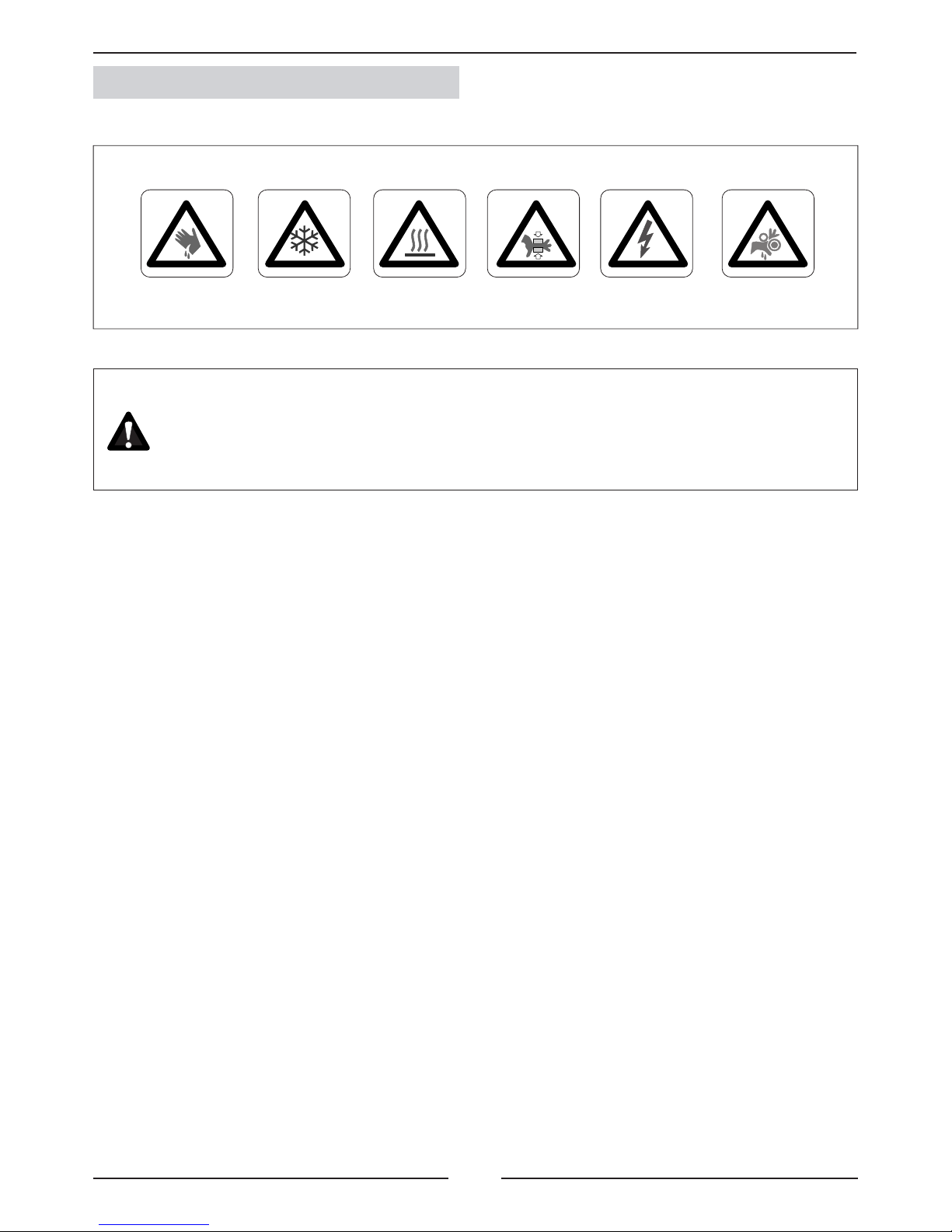
POINTS TO BEAR IN MIND
DANGER AND WARNING SIGNS
Page 4
3
1 ºC
2 ºC
1 ºC
2 ºC
1 ºC
2 ºC
1 ºC
2 ºC
DATA PAGE FOR UNIT COMMISSIONING
UNIT:
INSTALLER TEL:INSTALLER:
CONTROL PANEL IDENTIFICATION CODE:
INSTALLATION ADDRESS:
SERIAL Nr:
CHECKS:
DATE OF COMMISSIONING:
SUPPLY VOLTAGE:
RATED VOLTAGE OF THE UNIT:
UNIT ON SHOCK ABSORBERS
DRAINAGE WITH TRAP
MAIN POWER SUPPLY CONNECTION
CONTROL PANEL CONNECTION
COMPRESSOR OIL LEVEL INDICATOR
YES NO
DATA INPUT:
COOLING CYCLE
Air intake temperature to the outdoor coil:
Air output temperature to the outdoor coil:
High pressure:
Low pressure:
circuit 1
circuit 2
circuit 1
circuit 2
Air intake temperature to the outdoor coil:
Air output temperature to the outdoor coil:
High pressure:
Low pressure:
circuit 1
circuit 2
circuit 1
circuit 2
HEATING CYCLE
ELECTRIC POWER CONSUMPTION (Amps)
Compressor 1
Compressor 3
Outdoor fan section 1
Outdoor fan section 2
Options installed:
Comments:
Compressor 2
Compressor 2
INSTALLER ADDRESS:
Compressor 1
Compressor 3
Outdoor fan section 1
Outdoor fan section 2
Page 5
4
C S C 020 S N M 3 M
CSC
CSH
020S
CSC
CSH
025S
CSC
CSH
030S
CSC
CSH
035S
CSC
CSH
040S
CSC
CSH
045D
CSC/CDC
CSH/CDH
055D
CSC/CDC
CSH/CDH
070D
CSC/CDC
CSH/CDH
085D
CSC
CSH
100D
257 290 297 352 365 443 524 549 581 865
262 295 302 357 370 448 529 554 586 870
7600 8500 10000 12000 11700 14000 20000 21000 22000
15500+11700
CSC
CSH
020S
CSC
CSH
025S
CSC
CSH
030S
CSC
CSH
035S
CSC
CSH
040S
CSC
CSH
045D
CSC/CDC
CSH/CDH
055D
CSC/CDC
CSH/CDH
070D
CSC/CDC
CSH/CDH
085D
CSC
CSH
100D
8.25 10.1 11.8 15.5 16.9 20.2 23.5 31 33.8 42.5
1.45 1.89 2.69 2.69 2.69 3.63 5.38 5.38 7.26 7.75
9.7 11.99 14.49 18.19 19.59 23.83 28.98 36.38 41.06 50.25
15 21 22 25.6 31 42 44 51.2 62 77.6
2.59 3.45 4.8 4.8 4.8 6.48 9.6 9.6 12.96 13.4
17.59 24.45 26.8 30.4 35.8 48.48 53.6 60.8 74.96 91
88.4 97.8 105.1 139.1 152.7 121.8
131.9/
210.2
169.5/
278.2
191.9/
308.8
207.9
3~400V 50Hz
1.- GENERAL CHARACTERISTICS
1.1.- PHYSICAL DATA
Unit
COMPACTAIR
C: Cooling only
H: Heat pump
Type of refrigerant
M: R-410A
Approximate cooling
capacity in kW
S: Outdoor unit Split
D: Outdoor unit Multi-split
S: One Circuit
D: Two Circuits
No heat
Number
of revision
M: 400V/3/50
CSC/CDC: Cooling only unit R-410A.
CSH/CDH: Heat pump unit R-410A.
UNIT MODELS
Compressor (Nr. / Type)
1/Scroll 1/Scroll 1/Scroll 1/Scroll 1/Scroll 2/Scroll 2/Scroll 2/Scroll 2/Scroll 2/Scroll
Net Weight
(Kg)
CSC/CDC Cooling only unit (Kg.)
CSH/CDH Heat pump unit (Kg.)
Air ow (m3/h)
Refrigerant charge
NITROGEN(*)
(*) The units are supplied with nitrogen gas; this must be
removed and the unit charged with refrigerant R-410A,
depending on unit model.
(see page 23 to calculate refrigerant charge for model CSC/
CDC and CSH/DCH units to work with indoor units CIC/CIH).
R-410A factory refrigerant precharge kit is available as an
option.
1.2.- ELECTRICAL DATA
ELECTRICAL CONSUMPTION FOR STANDARD UNITS
UNIT MODELS
Maximum absorbed power (kW)
Compressor
Fan
Total power
Maximum current (A)
Compressor
Fan
Total current
Start up current (A)
Voltage V/f (50Hz)
1.3.- OPERATING LIMITS (For installation with CIC-CIH units)
OPERATING LIMITS FOR (COOLING ONLY) UNITS
COOLING CYCLE
OPERATION
INDOOR TEMPERATURE
OUTDOOR TEMPERATURE
MAXIMUM TEMPERATURES
MINIMUM TEMPERATURES
+10ºC STANDARD UNIT
0ºC (*)
-15ºC (**)
INDOOR TEMPERATURE
MAXIMUM TEMPERATURES
COOLING CYCLE
OPERATION
HEATING CYCLE
OPERATION
INDOOR TEMPERATURE
OUTDOOR TEMPERATURE
27ºC
(With 20ºC outdoor temperature)
(*) With option kit low temperature 0ºC. (**) With option kit low temperature -15ºC.
OPERATING LIMITS FOR (HEATING PUMP) UNITS
DB: Dry bulb temperature. WB: Wet bulb temperature
(*) With option kit low temperature -15ºC.
MINIMUM TEMPERATURES
OUTDOOR TEMPERATURE
32ºC DB / 23ºC WB
21ºC DB / 15ºC WB
27ºC DB
32ºC DB / 23ºC WB
15ºC DB
21ºC DB / 15ºC WB
-12ºC
(With 20ºC indoor temperature)
45ºC (020-025-030-045-055)
47ºC (035-040-070-085-100)
45ºC (020-025-030-045-055)
47ºC (035-040-070-085-100)
0ºC UNIDAD ESTÁNDAR
-15ºC (*)
Page 6
5
055D
7000 8000 9000 10000 10700
741 299 264 225 160 96
709 271 235 195 137 83
677 242 206 165 11 3 70
645 213 178 135 73 57
613 184 149 105 32 44
070D
7350 8400 9450 10500 11200
741 272 230 182 122 66
709 243 201 153 98 50
677 213 172 124 74 33
645 184 142 95 44 16
613 154 11 3 66 13 -0.4
085D
7700 8800 9900 11000 11750
751 277 235 187 126 69
719 247 199 159 101 51
686 208 162 120 71 36
654 181 139 89 24 15
621 154 11 2 65 12 n/a
020S
5300 6100 6850 7600 8100
751 178 156 134 104 77
719 162 140 11 8 89 64
686 141 11 8 96 67 38
654 124 101 78 47 6
621 108 86 64 35
(rpm)
(m3/h)
025S
5950 6800 8500 9100
841 223 195 126 91
805 202 174 107 74
769 177 148 88 44
732 154 125 63 7
696 135 107 40 4
(rpm)
(m3/h)
030S
7000 8000 9000 10000
934 272 234 194 142
894 246 208 168 11 7
854 213 175 134 84
814 186 146 106 55
773 161 123 82 36
(rpm)
(m3/h)
035S
8400 9600 10800 12000 12850
741 209 191 171 146 125
709 189 171 152 126 105
677 168 151 132 107 87
645 148 131 11 2 88 68
613 128 111 92 69 50
(rpm)
(m3/h)
040S
8200 9350 10525 11700 12500
741 205 188 170 148
709 185 168 150 128 11 0
677 163 146 128 106 89
645 143 127 109 87 68
613 126 11 0 91 69 51
(rpm)
(m3/h)
045D
9800 11200 12600 14000
829 237 213 183 136
794 235 187 156 111
758 233 161 130 86
722 231 135 104 72
686 229 109 77 57
(rpm)
(m3/h)
100D (C1)
10850 12400 13950 15500 16600
846 239 210 171 125
801 207 180 138 92 58
756 175 150 105 58 26
711 143 121 72 26 n/a
666 111 91 39 n/a n/a
(rpm)
(m3/h)
100D (C2)
8200 9350 10525 11700 12500
743 201 187 157 141 11 9
711 199 167 136 161 101
679 197 148 11 6 102 83
647 195 128 95 84 64
615 193 108 75 65 46
(rpm)
(m3/h)
(rpm)
(m3/h)
(rpm)
(m3/h)
(rpm)
(m3/h)
•
•
•
Pulley closed
1 turn
2 turns
3 turns
4 turns
Pulley closed
1 turn
2 turns
3 turns
4 turns
Pulley closed
1 turn
2 turns
3 turns
4 turns
Pulley closed
1 turn
2 turns
3 turns
4 turns
Pulley closed
1 turn
2 turns
3 turns
4 turns
Pulley closed
1 turn
2 turns
3 turns
4 turns
Pulley closed
1 turn
2 turns
3 turns
4 turns
Pulley closed
1 turn
2 turns
3 turns
4 turns
Pulley closed
1 turn
2 turns
3 turns
4 turns
Pulley closed
1 turn
2 turns
3 turns
4 turns
Pulley closed
1 turn
2 turns
3 turns
4 turns
Illegal position because of the limit of engine power Note: The unit leaves factory with the pulley t to 2 open turns
1.4.- FAN PERFORMANCES (Available static pressure Pa.)
STANDARD UNITS WITHOUT OPTIONALS
1.- GENERAL CHARACTERISTICS
Page 7
6
(ELEMENTO OPCIONAL)
045
DS
SVL3
C2
LP2
CH3
HP2
PT2
SVL1
C1
LP1
CH1
HP1
PT1
CIC 045
UNIDAD INTERIOR UNIDAD EXTERIOR
CSC 045
OS
SVL3
SVL1
DS
LPT2
HPT1
HPT2
CH1
CH3
OS
LPT1
CSC 020/025/030/035/040
UNIDAD INTERIOR
CIC 020/025/030/035/040
UNIDAD EXTERIOR
SVL1
HP1
(ELEMENTO OPCIONAL)
C1
CH1
DS
OS
LPT1
HPT1
HPT1
LPT1
HPT2
LPT2
1.- GENERAL CHARACTERISTICS
INDOOR UNIT OUTDOOR UNIT
OPTION ELEMENT
Scroll compressor
Fan
Expansion valve
Filter drier
Service valve
option
Service valve
option
Fan motor
Coil
Coil
INDOOR UNIT
OUTDOOR UNIT
OPTION ELEMENT
Scroll compressor
Scroll compressor
Fan
Coil
Expansion valve
Expansion valve
Filter drier
Filter drier
Service valve
option
Suction accumulator
(Long distance connection option).
Suction accumulator
(Long distance connection option).
Fan motor
Coil
Pressure gauge. (5/16” to be tted by the installer).
Discharge sensor. (With C50 control).
Liquid solenoid valve. (Long distance option).
To be connected by the installer to indoor units.
Liquid solenoid valve. (Long distance option).
To be connected by the installer to indoor units.
Low pressure switch, circuit 1.
Low pressure switch, circuit 2.
High pressure transducer circuit 1.
High pressure transducer, circuit 2.
Crank case heater. (Low ambient 0ºC or -15ºC option).
Crank case heater. (Low ambient 0ºC or -15ºC option).
Outdoor temperature sensor
Service valve
option
Service valve
option
Service valve
option
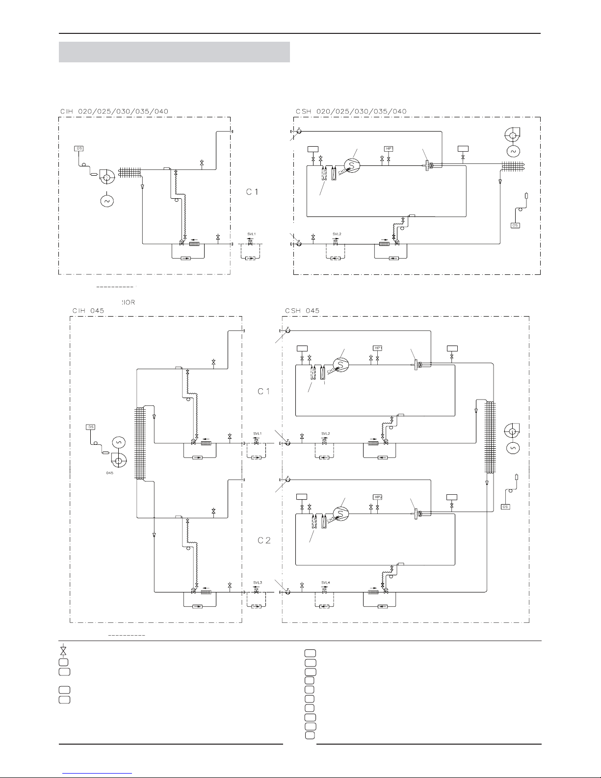
1.5.- PIPING DRAWINGS COOLING ONLY UNITS
OPTION ELEMENT
Suction accumulator
(Long distance connection option).
Page 8
7
(ELEMENTO OPCIONAL)
055/070/085
DS
SVL3
C2
LP2
CH3
HP2
PT2
SVL1
C1
LP1
CH1
HP1
PT1
CIC 055/070/085
UNIDAD INTERIOR UNIDAD EXTERIOR
CSC 055/070/085
OS
SVL3
SVL1
DS
HP1
HP2
CH1
CH3
OS
LPT1
LPT1
HPT1
HPT2
LPT2
LPT2
HPT1
HPT2
1.- GENERAL CHARACTERISTICS
1.5.- PIPING DRAWINGS COOLING ONLY UNITS
INDOOR UNIT
OUTDOOR UNIT
Scroll compressor
Scroll compressor
Fan
Coil
Expansion valve
Expansion valve
Filter drier
Filter drier
Service valve
option
Suction accumulator
(Long distance connection option).
Suction accumulator
(Long distance connection option).
Fan motor
Coil
Fan motor
Coil
Service valve
option
Service valve
option
Service valve
option
Pressure gauge. (5/16” to be tted by the installer).
Discharge sensor.
Liquid solenoid valve. (Long distance option).
To be connected by the installer to indoor units.
Liquid solenoid valve. (Long distance option).
To be connected by the installer to indoor units.
Low pressure transducer, circuit 1.
Low pressure transducer, circuit 2.
High pressure switch, circuit 1.
High pressure switch, circuit 2.
Crank case heater. (Low ambient 0ºC or -15ºC option).
Crank case heater. (Low ambient 0ºC or -15ºC option).
High pressure transducer, circuit 1
High pressure transducer, circuit 2.
Outdoor temperature sensor
OPTION ELEMENT
Page 9
8
SVL3
C2
DS
SVL1
C1
PT2
CH3
LP2
HP2
PT1
CH2
LP1
CH1
HP1
UNIDAD EXTERIOR
CSC 100
UNIDAD INTERIOR
CIC 100
(ELEMENTO OPCIONAL)
OS
DS
SVL1
DS
SVL3
LPT1
HP1
HP2
CH3
CH1
CH2
OS
HPT1
LPT1
LPT2
HPT2
LPT2
HPT1
HPT2
1.- GENERAL CHARACTERISTICS
Pressure gauge. (5/16” to be tted by the installer).
Discharge sensor.
Liquid solenoid valve (Long distance option).
To be connected by the installer to indoor units.
Liquid solenoid valve (Long distance option).
To be connected by the installer to indoor units.
Low pressure transducer, circuit 1.
Low pressure transducer, circuit 2.
High pressure switch, circuit 1.
Coil
Fan motor
Coil
Fan motor
Suction accumulator
(Long distance connection option).
Suction accumulator
(Long distance connection option).
1.5.- PIPING DRAWINGS COOLING ONLY UNITS
Scroll compressor
Scroll compressor
Scroll compressor
INDOOR UNIT
OUTDOOR UNIT
OPTION ELEMENT
Fan
Coil
Expansion valve
Expansion valve
Filter drier
Filter drier
Service valve option
Service valve option
Service valve option
Service valve option
Coil
High pressure switch, circuit 2.
Crank case heater. (Low ambient 0ºC or -15ºC option).
Crank case heater. (Low ambient 0ºC or -15ºC option).
Crank case heater. (Low ambient 0ºC or -15ºC option).
High pressure transducer, circuit 1.
High pressure transducer, circuit 1.
Outdoor temperature sensor
Page 10
9
SVL1
DS
SVL2
SVL3
HP1
HP2
CH3
CH1
SVL4
OS
(ELEMENTO OPCIONAL)
SVL1 SVL2
C1
CH1
DS
LP1 HP1
PT1
CSH 020/025/030/035/040
UNIDAD INTERIOR
CIH 020/025/030/035/040
UNIDAD EXTERIOR
OS
(ELEMENTO OPCIONAL)
SVL3 SVL4
045
DS
LP2
SVL1
HP2
SVL2
PT2
LP1 HP1 PT1
CH3
CH1
C2
C1
CIH 045
UNIDAD INTERIOR UNIDAD EXTERIOR
CSH 045
OS
HPT1
LPT1
HPT1LPT1
HPT2
LPT2
HPT1
HPT2
LPT1
LPT2
1.- GENERAL CHARACTERISTICS
1.5.- PIPING DRAWINGS HEAT PUMP UNITS
Scroll compressor
INDOOR UNIT
OUTDOOR UNIT
OPTION ELEMENT
4-way valve
INDOOR UNIT
OUTDOOR UNIT
Scroll compressor
4-way valve
Scroll compressor
4-way valve
OPTION ELEMENT
Fan
Expansion valve
Filter drier
Service valve
option
Service valve
option
Fan motor
Coil
Suction accumulator
(Remote connection option)
Coil
Check valve Check valve
Filter drier
Expansion valve
Check valve
Suction accumulator
Check valve
Coil
Fan motor
Coil
Fan
Expansion valve
Filter drier
Service valve option
Service valve option
Suction accumulator (Long
distance connection option)
Check valve Check valve
Filter drier
Expansion valve
Check valve
Suction accumulator
Check valve
Service valve option
Service valve option
Expansion valve
Filter drier
Suction accumulator (Long
distance connection option)
Check valve Check valve
Filter drier
Expansion valve
Check valve
Suction accumulator
Check valve
Pressure gauge. (5/16” to be tted by the installer).
Discharge sensor.
Liquid solenoid valve (Long distance option).
To be connected by the installer in the indoor unit.
Liquid solenoid valve (Long distance option).
Liquid solenoid valve (Long distance option).
To be connected by the installer in the indoor unit.
Liquid solenoid valve (Long distance option).
Low pressure transducer, circuit 1.
Low pressure transducer, circuit 2.
High pressure switch, circuit 1.
High pressure switch, circuit 2.
Crank case heater.
Crank case heater.
High pressure transducer, circuit 1.
High pressure transducer, circuit 2.
Outdoor temperature sensor.
Page 11

10
SVL1
DS
SVL2
SVL3
(ELEMENTO OPCIONAL)
SVL3 SVL4
055/070/085
DS
LP2
SVL1
HP2
SVL2
PT2
LP1 HP1 PT1
CH3
CH1
C2
C1
CIH 055/070/085
UNIDAD INTERIOR UNIDAD EXTERIOR
CSH 055/070/085
OS
HPT1LPT1
HPT2LPT2
HP1
HP2
CH3
CH1
SVL4
OS
HPT1
HPT2
LPT1
LPT2
1.- GENERAL CHARACTERISTICS
INDOOR UNIT
OUTDOOR UNIT
Scroll compressor
4-way valve
Scroll compressor
4-way valve
OPTION ELEMENT
Coil
Fan motor
Coil
Fan
Expansion valve
Filter drier
Service valve option
Service valve option
Suction accumulator (Long
distance connection option)
Check valve Check valve
Filter drier
Expansion valve
Check valve
Suction accumulator
Check valve
Service valve option
Service valve option
Expansion valve
Filter drier
Suction accumulator (Long
distance connection option)
Check valve Check valve
Filter drier
Expansion valve
Check valve
Suction accumulator
Check valve
Pressure gauge. (5/16” to be tted by the installer).
Discharge sensor.
Liquid solenoid valve (Long distance option).
To be connected by the installer in the indoor unit.
Liquid solenoid valve (Long distance option).
Liquid solenoid valve (Long distance option).
To be connected by the installer in the indoor unit.
Liquid solenoid valve (Long distance option).
Low pressure transducer circuit 1.
Low pressure transducer, circuit 2.
High pressure switch, circuit 1.
High pressure switch, circuit 2.
Crank case heater.
Crank case heater.
High pressure transducer, circuit 1.
High pressure transducer, circuit 2.
Outdoor temperature sensor.
Fan motor
Coil
1.5.- PIPING DRAWINGS HEAT PUMP UNITS
Page 12

11
UNIDAD EXTERIOR
SVL3
112D/128D
C2
DS
SVL1
C1
SVL4
PT2LP2
SVL2
HP2
C
H
2
C
H
1
PT1LP1 HP1
CSH 100
UNIDAD INTERIOR
CIH 100
(ELEMENTO OPCIONAL)
C
H
3
OS
DS
SVL1
DS
SVL2
SVL3
SVL4
HPT1
LPT1
HPT2LPT2
HP1
HP2
CH2
CH1
OS
HPT1
HPT2
LPT1
LPT2
CH3
1.- GENERAL CHARACTERISTICS
1.5.- PIPING DRAWINGS HEAT PUMP UNITS
INDOOR UNIT
OUTDOOR UNIT
OPTION ELEMENT
Scroll com-
pressor
Scroll compressor
Scroll compressor
4-way valve
4-way valve
Check valve
Liquid receiver
Fan
Expansion valve
Filter
drier
Service valve
option
Service valve
option
Fan motor
Coil
Suction accumulator (Long
distance connection option)
Coil
Check
valve
Check
valve
Filter
drier
Expansion valve
Check
valve
Suction accumulator
Check
valve
Service valve
option
Service valve
option
Fan
Coil
Filter drier
Check
valve
Check
valve
Expansion valve
Suction accumulator (Long
distance connection option)
Check
valve
Filter
drier
Expansion valve
Check
valve
Suction accumulator
Fan motor
Coil
Pressure gauge. (5/16” to be tted by the installer).
Discharge sensor.
Liquid solenoid valve (Long distance option).
To be connected by the installer to indoor units.
Liquid solenoid valve (Long distance option).
Liquid solenoid valve (Long distance option).
To be connected by the installer to indoor units.
Liquid solenoid valve (Long distance option).
Low pressure transducer, circuit 1.
Low pressure transducer, circuit 2.
High pressure switch, circuit 1.
High pressure switch, circuit 2.
Crank case heater.
Crank case heater.
Crank case heater.
High pressure transducer, circuit 1.
High pressure transducer, circuit 2.
Outdoor temperature sensor.
Page 13

12
CSC/CSH 20S/25S/30S/35S/40S/45D
23
A
30,5
C
B
345,5
25
929
47
33,5
41
D
D
E
30
020 - 025 - 030 S 035S - 040S - 045D
A 1194 1445
B 1000 1093
C 163,5 321,5
D 102,5 133
E 540 600
A
C
B
D
E
25
F
G
020 - 025 - 030 S 035S - 040S - 045D
A 371,5 420
B 564 622
C 288,5 403
D 1410 1500
E 204,5 252,5
F 467 543
G 77,5 74,5
CSC/CSH/CDC/CDH 55D/070D/85D
2251
143,5
143,5
953,5
345,5
25
929
47
33,5
23
41
98,5
98,5
670
57
953,5
373,5
518
493
1475
251,5
25
541
78,5
493
373,5
1.- GENERAL CHARACTERISTICS
1.6.- UNIT DIMENSIONS
Access to gas
and liquid lines
Power supply
cable entry
Electrical box
External drainage
- 3/4” thread
MODELS
“A” BOX “B” BOX
SPLIT - STANDARD HORIZONTAL DISCHARGE SPLIT - OPTIONAL VERTICAL DISCHARGE
MODELS
“A” BOX “B” BOX
Back view
Front view
SPLIT - STANDARD HORIZONTAL DISCHARGE SPLIT - OPTIONAL VERTICAL DISCHARGE
Access to gas
and liquid lines
(C2)
Access to gas
and liquid lines
(C1)
Back view
External drainage
- 3/4” thread
Electrical box
Power supply
cable entry
External drainage
- 3/4” thread
Front view
Power supply
cable entry
Page 14

13
CSC/CSH 100D
CSC/CSH 100D
23
1445
30,5
321,5
1093
345,5
25
929
47
33,5
41
133
133
600
30
23
1445
30,5
321,5
1093
345,5
25
929
47
33,5
41
133
133
600
30
420
403
622
1500
252,5
25
543
74,5
420
403
622
1500
252,5
25
543
74,5
221,5
1.- GENERAL CHARACTERISTICS
1.6.- UNIT DIMENSIONS
SPLIT - STANDARD HORIZONTAL DISCHARGE
SPLIT - OPTIONAL VERTICAL DISCHARGE
Back view
Access to gas
and liquid lines
(C2)
Access to gas
and liquid lines
(C1)
Front view
Electrical box
Power supply
cable entry
External drainage
- 3/4” thread
External drainage
- 3/4” thread
Page 15

14
2.- INSTALLATION
2.1.- PRELIMINARY PREPATATIONS
All INSTALLATION, SERVICE and MAINTENANCE work
must be carried out by QUALIFIED PERSONNEL.
The unit must be transported in a VERTICAL POSITION on its metal mounting frame. Any other position may cause
serious damage to the machine. When the unit is received, it should be checked to assure that it has received no
shocks or other damage, following the instructions on the packaging. If there is damage, the unit may be rejected by
notifying the LENNOX Distribution Department and stating why the machine is unacceptable on the transport agent’s
delivery note. Any later complaint or claim made to the LENNOX Distribution Department for this type of damage
cannot be considered under the Guarantee.
Sufcient space must be allowed to facilitate installation of the unit.
The unit may be mounted outdoors. When the unit is mounted on the oor, ensure that the position is not subject
to ooding.
When positioning the unit, be sure that the Rating Plate is always visible since this data
will be necessary to ensure correct maintenance.
The units are designed to be installed with ducts designed by qualied technical staff. The joints to be used between
ducts and openings in the unit should be Elastic Joints. Avoid the use of BYPASS joints between the extraction air
and input air. The structure where the unit is placed must be able to support the weight of the unit during operation.
2.2.- UNIT RECEPTION
All units have Metal Bedplate Proles.
If unloading and installation require the use of a crane, then the suspension cables must be secured as shown
in the diagram.
How to hoist the unit
Use
separators
Defrosting:
To avoid ice accumulation in the driptray , it may be necessary to install an electrical heater and
inside the drainage connection , to drain correctly the water
The drainage must be always accessible through the indoor part , in order to remove easily the
dirty than may be accumulated.
Page 16

15
1
3
5
2
4
6
7
3
1
2
1
2
3
2
B A B A
7
THE VENTILATION IS FORMED BY:
1.- Centrifugal fan ( single or double).
2.- Activating motor.
3.- Fixed pulley at the fan.
4.- Adjustable pulley at the motor fan.
5.- transmission pulley or pulleys.
6.- Base of the motor with displacement system for
tensioning of belts.
7.- Tensing screw.
FLOW REGULATION IN THE FANS
The fan in the outdoors units have a variable pulley incorporated into the activating motor, by which it is possible to vary,
when the fan is off its diameter to modify the air ow of the unit, as required.
1. Fixed part
2. Mobil part
3. Fixing screw
CLOSE PULLEY:
To increase the fan ow, turn the mobile part in
direction “B” (Clock wise).
OPEN PULLEY:
To reduce the ow, turn in direction “A”
(Unclock wise).
TENSION OF BELTS
The belts can be easily tensioned through the
tensing screw incorporated into the bases of
the motor of the transmitting units which also
enables a good servicing to be carried out.
When the tensing screw is moved, the motor
fan is moved to the sides in order to tension
the pulley.
DISPLACEMENT
SIMPLE PULLEY DOUBLE PULLEY
VARIABLE PULLEYS
2.3.- OPTIONAL OPERATIONS PRIOR TO UNIT INSTALATION
2.- INSTALLATION
Page 17

16
2.- INSTALLATION
2.3.- UNIT LOCATION
- The bedplate is made up of two metal channels, capable of with standing the weight of the units whether hung from the ceiling or
mounted on the oor.
- If the unit is oor mounted, then the proles should be isolated with shock absorbing material such as anti-vibration or pads. Keep in
mind that fans rotate at approximately 850 rpm.
For the ones with variable pulley belts, see performances tables.
- The unit is able to work in normal radioelectronic conditions for commercial and residential installations. For any other conditions
please consult.
- If the outside temperature in the area where the heat pump unit is to be installed is low or the cycle functioning are too long, it may
necessary to install an electrical heater, below the likely coils on the drip tray, which avoids the causing of ice in the coil during defrost
cycle.
- If the outdoor unit is going to be installed outside, it is needed to install isolation around the panel of electrical box, to make sure it
became hermetic as well as isolate the electrical panel to avoid condensations. It is also needed to install isolation around the access
panels and seal joints of the casing to make sure the unit became hermetic.
UNIT INSTALLED ON SHOCK ABSORBERS
Floor supports
(shock absorbers)
(*) If the unit is mounted outdoors, without discharge duct, the installer must mount a discharge protection grill in
the outlet of the outdoor fan.
grid (*
)
Page 18
17
1 m.
1 m.
1 m.
1 m.
2%
2%
2.- INSTALLATION
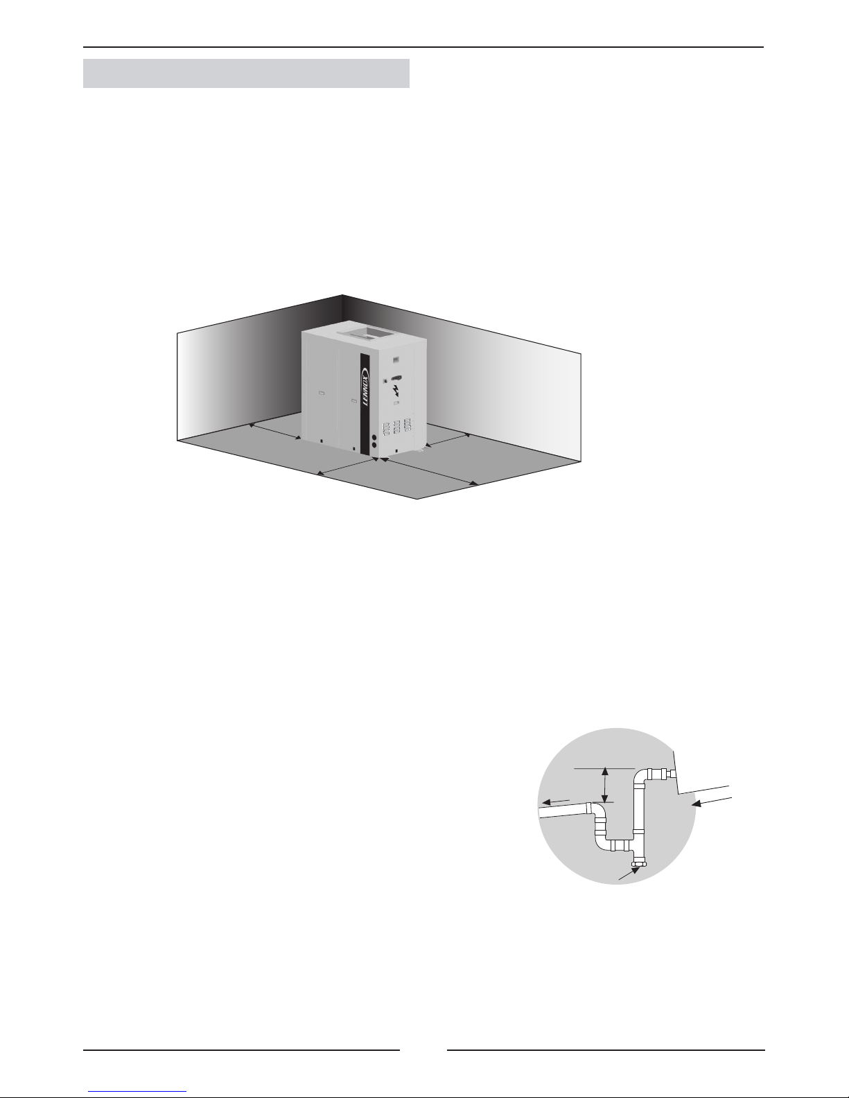
2.4.- INSTALLATION CLEARANCES
Clearance around the unit for service and maintenance
SERVICE SPACE
Space should be left free for access or servicing, to ease the installation of cables, drainage connections, electric installation and
cleaning lters, as well as easy access to the unit.
LOCATION
The unit can be installed outside. If it is installed, air entry and exit ducts should be tted. Both the interior and exterior unit should be
assembled on bases previously made and stood on absorbent and antivibrating material to avoid the vibrations being transmitted to
the structure of the building.
2.6.- DRAINS
All the indoor and outdoor sections of these units have a 3/4” steel threaded drain pipe welded to the condensation tray.
Drainage pipes will be tted for each tray through a siphon with a height
difference of 80 mm. to avoid drainage problems from the depression formed
by the fans. The pipes should have an inclination of 2% to ease drainage of
condensation.
Mín. 80 mm.
Inspection and cleaning stopper
Also slightly tip the unit (2%) toward the drainage side. Check that the condensation trays are clean and free from dirt and other debris
from the works and that water drains correctly.
UNIT
Page 19

18
2.- INSTALLATION
2.7- REFRIGERANT CONNECTIONS
The unit is supplied with the gas and liquid lines sealed with copper caps
outside the casing with possibility to install pipe lines (unless the unit is supplied with the factory precharged refrigerant kit (option) or service valves
kit (option).
Standard units are lled with Nitrogen gas, which must be removed before any operation on the unit.
As an option, the unit can be supplied with service valves on the gas and liquid lines, with Nitrogen charge
(N2) or refrigerant charge (R-410A).
FOR STANDARD UNITS AND UNITS SUPPLIED WITH SERVICE VALVES PROCEED AS FOLLOW:
1. Remove the nitrogen gas through the high and low 5/16” service ports located inside and provide a low vacuum for safety.
2. Remove the caps from the connecting lines.
3. Braze the piping connection lines. Select piping diameter from TABLE 1.
(When brazing refrigerant pipes, nitrogen gas must be supplied into the pipes through the service ports to remove the air).
4. Leak test:
Add nitrogen gas, check that a pressure of 5 kg/cm2 has been reached and that there are no leaks in the circuit or brazing
by applying soapy water to the pipes which will cause the bubbles to form where there are leaks.
To detect small leaks, proceed as follows:
Add nitrogen gas and check that a pressure of 25 kg/cm2 has been reached, there are no leaks if the pressure remains the same
for at least 24 hours and the nal pressure is not less than 10% below the initial pressure.
5. Ensure that the gas line is insulated.
6. Evacuation:
Remove the nitrogen gas, connect the gauge manifold and vacuum pump to both the liquid and gas lines, fully open the gauge
manifold valve and switch on the vacuum pump. Check to make sure the gauge shows a pressure of -750mm Hg. Once a level
of -750mm Hg is reached, keep the vacuum pump running for at least one hour.
7. Refrigerant charge:
- Check TABLE 3.1. and 3.2. for the amount of refrigerant charge, depending on the length and size of the pipe connections.
- Disconnect the vacuum pump and connect to the refrigerant-charging bottle. Open the charging pump and purge the air from
the hose at the pressure gauge manifold.
- Set up the amount of additional refrigerant on the weighing scale, open the high pressure and charged in the liquid state. If the
total amount of refrigerant charge has not been reached because the pressure is balanced, turn off the high side of the gauge
manifold, turn on the unit, and add the remaining amount of the refrigerant charge required slowly through the low side of the
pressure gauge. (With R-410A refrigerant, the charging bottle must be in a vertical position and charged in the liquid state).
Close the pressure gauge, disconnect it from the from the service port of the unit and t caps on the service ports. The unit is
then ready to operate.
During installation, keep the gas and liquid pipes covered, in order to prevent humidity and dirt
from entering them.
Take special care that the refrigerant pipes are insulated.
Avoid collapse on lines installation.
FOR UNITS SUPPLIED WITH SERVICE VALVES AND FACTORY PRECHARGED REFRIGERANT KIT, PROCEED AS FOLLOWS:
1. Release the refrigerant pressure from the connecting line through
the service port located in that line.
2. Remove the caps from the connecting lines.
3. Braze the interconnection line to the indoor unit.
4. With the service ports closed, evacuate and connect the vacuum pump
to the 5/16” service port on the connecting line to achieve a pressure of
-750mm Hg; after that, keep the vacuum pump running for at least one
hour in order to provide a vacuum to the connecting lines and the indoor
unit. Disconnect the vacuum pump.
5. Refrigerant charge:
Remove vacuum pump and connect the refrigerant bottle. Check TABLE 2 for refrigerant charge per meter of copper pipe
for the corresponding model.
Adjust the amount of refrigerant on the weighting scale and open the pressure gauge to charge in liquid state.
(with R-410A refrigerant, the charging bottle must be in a vertical position and it is important to charge in the liquid state).
Close the pressure gauge, disconnect it from the service port of the unit and t the caps.
6. Open the service valves.
7. The unit is ready to operate.
Refrigerant pipe
lines
Copper cap
Brazing
Service
port
Service
valve
To outdoor
unit piping
Copper tube to
connect to
indoor unit
Copper
cap
To the
indoor unit
Page 20

19
2%
2
1
B
L
2%
2%
2
1
C
L
2%
2%
A
L
2
1
2.7- REFRIGERANT CONNECTIONS
To locate the outdoor and the indoor units, refer to the following information:
POSITION C : Install a siphon at the base of the vertical of the gas line; no
more siphons are necessary. Maximum vertical length 16m.
NOTE: The refrigerant connections are brazing
connections. Service valves can be supplied as
option if required.
- THE GAS LINE MUST BE ALWAYS INSULATED.
- THE HORIZONTAL LINES MUST BE TIPPED AT LEAST 2% TOWARD THE OUTDOOR UNIT.
- THE MAXIMUM SPEED INSIDE LINES SHOULD NOT BE MORE THAN 15 m/seg.
OUTDOOR UNIT
INDOOR UNIT
A,B,C : Unit positions
L : Total length
1 = Gas line
2 = Liquid line
OUTDOOR UNIT
INDOOR UNIT
OUTDOOR UNIT
INDOOR UNIT
POSITION A : A syphon suction must be installed at the base of the vertical of the
gas line, and syphons must be installed every 8 meters upward. The minimum speed
suction must not be below 6m/s. Maximum vertical length 16m.
POSITION B : Tip the lines toward the outdoor unit. Make special attention
to line length longer than 10m and avoid collapse on pipe lines installation.
2.- INSTALLATION
Page 21

20
1/2” 7/8” 108
5/8” 1-1/8” 177
5/8” 1-3/8” 182
3/4” 1-3/8” 265
3/4” 1-5/8” 271
7/8” 1-5/8” 374
020S 025S 030S 035S 040S 045D 055D 070D 080D 100D
C1
1/2” 5/8” 5/8” 5/8” 5/8” 5/8” 5/8” 5/8” 5/8” 3/4”
C2
n/a n/a n/a n/a n/a 5/8” 5/8” 5/8” 5/8” 5/8”
C1
7/8” 1 1/8” 1 1/8” 1 3/8” 1 3/8” 1 1/8” 1 1/8” 1 3/8” 1 3/8” 1 5/8”
C2
n/a n/a n/a n/a n/a 1 1/8” 1 1/8” 1 3/8” 1 3/8” 1 3/8”
6 12 8 18 12 12 8 18 12 12
C1
5/8” 5/8” 5/8” 3/4” 3/4” 5/8” 5/8” 3/4” 3/4” 7/8”
C2
n/a n/a n/a n/a n/a 5/8” 5/8” 3/4” 3/4” 3/4”
C1
1 1/8” 1 1/8” 1 3/8” 1 3/8” 1 5/8” 1 1/8” 1 3/8” 1 3/8” 1 5/8” 1 5/8”
C2
n/a n/a n/a n/a n/a 1 1/8” 1 3/8” 1 3/8” 1 5/8” 1 5/8”
12 18 18 18 18 18 18 18 18 12
TABLE 1: REFRIGERANT LINES SELECTION
From 40 m to 65 meters , the long distance kit is required.
n/a: not available
- IN MODEL 100D THE REFRIGERANT PIPES ARE FROM DIFFERENT SIZE . THE BIGEST SIZE CORRES-
PONDS TO CIRCUIT C1 AND THE SMALLEST ONE TO THE C2 CIRCUIT
The unit is supplied with brazing connections. As an option , the unit can be supplied with gas precharge from the factory ; in that case only the TABLE 2 has to be taken into account. ( this option includes the service valves).
TABLE 2 : EXTRA REFRIGERANT CHARGE R410A BY METER OF COPPER PIPE
Liquid Gas gr/m
The unit is precharged from factory with nytrogene . The installer should remove this gas and charge the units
with the charge of refrigerant R410A , shown in the following tables plus the charge by additional meter shown in
the TABLE 2
In the double circuit units , check before connecting C1 and C2 circuits , that they are the same circuit for the indoor
and the outdoor section
REFRIGERANT LINES
UNIT - MODEL
Total line length
(refrigerant line
length between
indoor and
ourtoor units)
0 to 30 m.
(Standard
conection
unit)
Ø Lquid
Ø Gas
Max. ner of bends
30 to 65 m.
Ø Liquid
Ø Gas
Max. ner of bends
2.7- REFRIGERANT CONNECTIONS
2.- INSTALLATION
Page 22

21
020 025 030 035 040 045 055 070 085 100
C1 4800 5950 6700 8650 10000 5700 6800 8600 10250 13000
C2 ------ ------ ------ ------ ------ 5700 6800 8600 10250 9200
020 025 030 035 040 045 055 070 085 100
C1 5000 6150 6900 8950 10350 5850 7000 8850 10600 13450
C2 ------ ------ ------ ------ ------ 5850 7000 8850 10600 9500
055 070 085
C1 6800 8600 10250
C2 6800 8600 10250
055 070 085
C1 7000 8850 10600
C2 7000 8850 10600
020S
025S
030S
035S
040S 5 x 10mm²
045S
055D
070D
085D
100D
2.- INSTALLATION
2.7- REFRIGERANT CONNECTIONS
Charge of R-410A refrigerant (g) for 0 meters of line (Cooling only)
Charge of R-410A refrigerant (g) for 0 meters of line (Heat pump)
Charge of R-410A refrigerant (g) for 0 meters of line (Cooling only)
Charge of R-410A refrigerant (g) for 0 meters of line (Heat pump)
TABLE 3.1.: REFRIGERANT CHARGE
C1: Circuit 1. C2: Circuit 2.
REFRIGERANT CHARGE FOR THE SET:
EXAMPLE:
To install a CSH 030 + CIH 030 set, with 22m refrigerant line length between the outdoor and indoor units,
the refrigerant charge must be calculated as follows:
1. TABLE 1 (p. 20) shows that for 22m of line length between the indoor unit and outdoor units, the line sizes are:
liquid 5/8” and gas 1 1/8”.
2. TABLE 2 (p. 20) shows, for line sizes of 5/8”-1 1/8”, the charge per meter of line is: 177 g/m x 22m = 3894 g.
3. TABLE 3.1 shows charge of refrigerant for a set with 0m line length is: 6900 g.
4. To determine the charge of the set:
Add the charge in the refrigerant lines + the charge in the indoor unit and outdoor refrigerant units.
Total charge for the set: 3894 + 6900 = 10794 g
Note: If the outdoor unit includes the factory pre-charged kit, only the weight of refrigerant per meter of line in TABLE 2
is taken into account.
TABLE 3.2.: CHARGE OF REFRIGERANT FOR MULTI-SPLIT SYSTEM
Page 23

22
OS
HR/T
DS
AS
AS
HR/T
DPT
DIFS
RS
3
BAC
2
DADS
LDRP
CO2
RS
HR/T
6
5
4
PT1
PT2
1
OS
AS
FREE-COOLING 4
020S
5 x 4mm² 5 x 10mm²
4 x 1,5 mm²
4 x 2,5 mm²
+
6 x 1,5 mm²
4 x 4 mm²
+
6 x 1,5 mm²
4 x 6 mm²
+
6 x 1,5 mm²
4 x 6 mm²
+
7 x 1,5 mm²
7 x 1,5mm²
4 x 1,5mm² N/A
025S
5 x 6mm²
5 x 16mm²
030S
035S
3 x 25mm²+
2 x 16mm²
4 x 1,5 mm²
4 x 4 mm²
+
6 x 1,5 mm²
4 x 6 mm²
+
6 x 1,5 mm²
4 x 10 mm²
+
6 x 1,5 mm²
4 x 10 mm²
+
7 x 1,5 mm²
040S 5 x 10mm²
045S
5 x 16mm²
3 x 35mm²+
2 x 16mm²
055D
3 x 50mm²+
2 x 25mm²
4 x 1,5 mm²
(STD/HP1)
4 x 2,5 mm²
(HP1/HP2)
4 x 6 mm²
+
6 x 1,5 mm²
3 x 10
mm²+PE
+
6 x 1,5 mm²
4 x 16 mm²
+
6 x 1,5 mm²
4 x 16 mm²
+
7 x 1,5 mm²
4 x 1,5mm²
4 x 1,5mm²
070D
3 x 25mm²+
2 x 16mm²
3 x 70mm²+
2 x 35mm²
085D
100D
3 x 35mm²+
2 x 16mm²
3 x 95mm²+
2 x 50mm²
2 x (4 x 4mm²)
+ 10 x 1,5mm²
+ 6 x 1mm²
4 x 2,5 mm²
(STD/HP1)
2 x (4 x 1,5
mm²)
(HP1/HP2)
4 x 10 mm²
+
6 x 1,5 mm²
4 x 16 mm²
+
6 x 1,5 mm²
4 x 25 mm²
+
6 x 1,5 mm²
4 x 25 mm²
+
7 x 1,5 mm²
4 x 2,5mm²
2.- INSTALLATION
2.8.- ELECTRICAL CONNECTIONS
- BEFORE MAKING ANY ELECTRICAL CONNECTIONS, ENSURE THAT ALL CIRCUIT BREAKERS ARE OPEN.
- IN ORDER TO MAKE THE ELECTRICAL CONNECTIONS, FOLLOW THE ELECTRICAL DIAGRAM SUPPLIED WITH THE UNIT.
Note: The length of all cables for connection with indoor unit must be less than 65 m.
To connect by installer
OUTDOOR
SECTION
Electrical
box
POWER SUPPLY
POWER SUPPLY
POWER
SUPPLY 1
POWER
SUPPLY WITH
E.H. 1’
CONNECTION
BETWEEN
OUTDOOR UNITS
FAN 2
BATERÍA ELÉCTRICA 3
EXHAUST
FAN 5
RETURN
FAN 6
STANDARD MEDIUM HIGH
MODULA-
TING
Page 24

23
DS
OS
AS
RS
RS HR/T
CO2
DPT
OS HR/T
AS HRT
DIFS
2 x 1,5 mm²
LDRP
7 x 1,5 mm²
DADS
5 x 1,5 mm²
BAC
4 x 1,5 mm²
2.- INSTALLATION
2.8.- ELECTRICAL CONNECTIONS
VOLTAGE OPERATING LIMITS: 342-462V
COMFORT AND SERVICE TERMINAL CONNECTION
CONNECTION OF CONTROL ELEMENTS:
COMPONENT
Discharge sensor STANDARD 2 x 1 mm² (shielded)
Outdoor sensor STANDARD 2 x 1 mm² (shielded)
Remote ambient sensor STANDARD 2 x 1 mm² (shielded)
Remote duct sensor OPTION 2 x 1 mm² (shielded)
Duct remote sensor for enthalpic free-cooling OPTION 5 x 1 mm² (shielded)
CO2 Air quality probe. (Available only with enthalpic free-cooling) OPTION 4 x 1 mm² (shielded)
Air differential pressure transducer OPTION 3x 1 mm² (shielded)
Outdoor sensor for enthalpic free-cooling OPTION 5 x 1 mm² (shielded)
Remote ambient sensor for enthalpic free-cooling OPTION 6 x 1 mm² (shielded)
Dirty lter sensor OPTION
Long distance connection OPTION
Smoke detector OPTION
Hot water coil OPTION
Page 25

24
BM60
CH1
BM60
RS485
RS232
230V
BMS
BM60
BM60
BM60
CH2
CH3 CH4
RT12
LAN
J11
J10
J11 J10
J11
J10
J11
J10
RT2
RT1
BM60 BM60 BM60 BM60
LAN
DT50
DT50
DT50
DT50
A
B
CA
B
C
A
B
C
A
B
C
DC60
DC60
DC60
DC60 DS60DS60 DS60
DS60
RT3
A master-slave connection is possible with version C50 units:
SERIAL
CARD
SERIAL
CARD
SERIAL
CARD
SERIAL
CARD
RS485 MODBUS
LON WORKS FTT 10A
BACNET
RS485 MODBUS
LON WORKS FTT 10A
BACNET
SERIAL
CARD
Cable c. section (mm2)
two wire S12E racing
from min. 0.2 a max. 2.5 mm
2
AWG 20/22
1000m. max.
Connect a 120 Ω 1/4 W
terminating resistor,
MODBUS only.
SERIAL
CARD
SERIAL
CARD
SERIAL
CARD
SERIAL
CARD
Cable c. section (mm2)
3 shielded pairs
AWG24
500m max.
Cable c. section (mm2)
3 shielded pairs
AWG24
500m max.
Cable c. section (mm2)
3 shielded pairs
AWG24
500m max.
Cable c. section (mm2)
3 shielded pairs
AWG24
500m max.
Cable c. section (mm2)
3 shielded pairs
AWG24
500m max.
COMMUNICATION CAPABILITIES
2.- INSTALLATION
2.9.- OPTIONS INSTALLATION
1. BMS MODBUS_RS485 connection.
2. BMS LONWORKS_Echelon connection.
3. BMS BACnet connection.
Page 26

25
3.1.- PRELIMINARY CHECKS BEFORE STARTUP
- Check that the power supply is the same as stated on the Rating Plate which is in agreement with the electrical
diagram for the unit and that cable sizes are correct.
- Check that tightness of the electrical connections to their terminals and to ground.
- Check the control panel connections.
(If the connection is incorrect, the unit will not operate and the control panel display will not light).
- Check with your hand that the fans are turning freely.
FIGURE FOR THE STANDARD UNIT CONFIGURATION FOR MODELS:
055D-070D-085D
CONTROL PANEL
3.- COMMISSIONING AND OPERATION
CHECK COMPRESSOR OIL LEVEL
- Part of the compressor oil is pumped to the system when the compressor starts, so for split systems part of the oil
can be placed in the system: piping lines, traps, evaporator, etc.
- The quantity of oil in the system depends on the refrigerant charge. The compressor cannot work with incorrect
or excessive refrigerant.
- It may be necessary to add oil to the system, depending on the piping length.
- See below an example of calculation of the oil quantity to be added to the system.
EXAMPLE:
CSH 030 + CIH 030 with 65m. (With remote option).
- Refrigerant charge = 6.33kg. (TABLE 3.1, p. 23).
- Refrigerant charge to add with 65m = 182g/m x 65 = 11.83kg. (TABLE 2, p. 22).
- Total refrigerant charge = 6.33 + 11.83 = 18.16kg.
- Oil compressor charge (l) = 3.25.
- Oil compressor charge (kg) = 2.925 (density = 0.9).
- Permissible quantity in the system (kg) = 0.03 (= 2.925 x 0.01).
- Permissible refrigerant charge (kg) = 6 (= 0.03/ 0.005).
- Excess refrigerant charge = 18.16 - 6 = 12.16
60.8g (= 12.16 x 5g) quantity of oil to be added to the system.
0.55l of oil to be added to the system.
In the event of having to add oil, remember the type of oil is synthetic POE.
The original oil charge, including the compressor, is ICI Emkarate RL32-3MAF. This type of oil must also be used
when replacing the oil completely.
If only topping up, RL32-3MAF or Mobil EAC Artic 22C can be used.
Page 27

26
3.- COMMISSIONING AND OPERATION
3.2.- PRELIMINARY CHECKS AT STARTUP
To start the unit, follow the instructions given in the User Manual for the control supplied with the unit
(requiring operation in any of the modes, cooling, heating, or automatic).
After a time delay, the unit will start.
With the unit operating, check that the fans are turning freely and in the correct direction.
CHECK THAT THE COMPRESSOR IS ROTATING IN THE CORRECT DIRECTION.
- If you have the option phase rotation indicator, use it to check the correct rotation.
- If you do not have three phase return lock, check the correct direction of rotation. The suction pressure decreases and the discharge
pressure increases when the compressor is started.
- If the connection is incorrect, rotation will be reversed, causing a high noise level and a reduction in the amount of current consumed.
If this occurs, the compressor’s internal protection system will operate to shut down the unit. The solution is to disconnect, reverse
two of the phases and connect again.
ASTP Protection is included with the unit compressors. See "Fault diagnosis" for more information.
WITH OPERATING UNIT, CHECK:
- Low pressure and high pressure.
- Use the evaporating and liquid temperature to calculate superheat and subcooling.
- Adjust the refrigerant charge and/or expansion valve according to the preceding values.
COMPRESSOR OIL LEVEL
The oil level must always be checked. When the compressor is at rest, the level should be between 1/4 and 3/4
in the sight glass, while when running the level should be between 3/4 and full.
In the event of having to add oil, remember the type of oil is synthetic POE.
The original oil charge in the compressor is ICI Emkarate RL32-3MAF. This type of oil must also be used when replacing the oil
completely.
When only topping up, RL32-3MAF or Mobil EAC Artic 22C can be used.
AIR INTAKE DUCT
OUTDOOR
SECTION
INLET AIR DUCT
OUTDOOR
SECTION
FLEXIBLE JOINT AT
OPENINGS
OUTDOOR
SECTION
TRAP
DRAIN PIPE
ACCESO A VENTILADOR EXTERIOR
DISCHARGE IN THE DOUBLE CIRCUIT UNITS
Always to be done through a common duct or plenum.
Page 28

27
3.- COMMISSIONING AND OPERATION
3.2.- PRELIMINARY CHECKS AT STARTUP
The unit must be installed in accordance with local safety codes
andregulations and can only be used in a well ventilated area.
Please readcarefully the manufacturer’s instructions before starting this unit
All work on the unit must be carried out by a qualied and
authorised employee.
Non-compliance with the following instructions may result in injury or serious accidents.
Work on the unit:
The unit shall be isolated from the electrical supply by disconnection and locking using the main isolating switch. Workers
shall wear the appropriate personal protective equipment (helmet, gloves, glasses,etc.).
Electrical system:
Electrical connections can become loose during transport. Please check them before starting-up the unit Compressors with
specic rotation direction. Check the correct rotation direction
of the fan before closing the compressor circuit breakers. If the
direction is incorrect, the phases must be reversed at the head
of the main switch. Work on electric components shall be performed with the power off (see below) by employees having valid
electrical qualication and authorisation.
Refrigerating circuit(s):
After more than 12 hours of power cut, the cranckcase heater
(compressor) should be powered for 5 hours before any return
to service. Non-compliance with this instruction can cause deterioration of the compressors.
Monitoring of the pressures, draining and lling of the system
under pressure shall be carried out using connections provided
for this purpose and suitable equipment.
To prevent the risk of explosion due to spraying of coolant and
oil, the relevant circuit shall be drained and at zero pressure before any disassembly or unbrazing of the refrigerating
parts takes place.
There is a residual risk of pressure build-up by degassing the
oil or by heating the exchangers after the circuit has been
drained. Zero pressure shall be maintained by venting the
drain connection to the atmosphere on the low pressure side.
The brazing shall be carried out by a qualied brazier. The
brazing shall comply according to code ASME section IX follo-
wing the procedures specic.
Before starting up:
-Test the circuit to the maximum working pressure(see the nameplate)
-Verify the operation of the high pressure swich.
-Check the piping and the components of the refrigerant circuit.
Replacing components:
In order to maintain CE marking compliance, replacement of
components shall be carried out
using spare parts, or using parts approved by Lennox.
Only the coolant shown on the manufacturer’s nameplate
shall be used, to the exclusion of all other
products (mix of coolants, hydrocarbons, etc.).
CAUTION:
In the event of re, refrigerating
circuits can cause an explosion
and spray coolant gas and oil.
Page 29

28
4.- MAINTENANCE
4.1.- PREVENTIVE MAINTENANCE
PREVENTIVE MAINTENANCE PREVENTS COSTLY REPAIRS.
THIS REQUIRES PERIODIC INSPECTIONS:
- GENERAL STATE OF THE CASING:
Furniture, paint, damage due to shocks, rust spots, levelling and supporting, condition of the shock absorbers, if installed, screwed panels, etc.
- ELECTRICAL CONNECTIONS:
State of hoses, tightness of screws, earthing, current consumption of the compressor and fans and check that the unit is receiving the correct voltage.
- COOLING CIRCUIT:
Check that the pressures are correct and that there are no leaks. Check that there is no damage to the pipe insulation, that the condition of the coils
is good and that they are not blocked by bits of paper or plastic drawn in by the air ow, etc.
- COMPRESSOR:
If a sight glass is tted, check the oil level.
Check the condition of the silentbloc mountings.
- FANS:
Check that fans turn freely and in the correct direction without excessive noise.
- CONTROL:
Check Set Points and normal operation.
4.2.- CORRECTIVE MAINTENANCE
IMPORTANT
MAKE SURE THAT THE UNIT IS FULLY DISCONNECTED FROM THE POWER SUPPLY WHEN CARRYING OUT
ANY TYPE OF WORK ON THE MACHINE.
If any component in the cooling circuit is to be replaced, follow these recommendations:
- Always use original replacement parts.
- If the component can be isolated, it is not necessary to remove the entire refrigerant charge, if the component cannot be isolating and the refri-
gerant charge is removed, it should be removed through the Schrader valves located in the outdoor section. Create a slight vacuum as a safety
measure.
- Regulation prohibits the release of refrigerant into the atmosphere.
- If cuts must be made in the pipe work, use pipe cutters. Do not use saws or any other tools that produce lings.
- All brazing must be carried out in a nitrogen atmosphere to prevent corrosion forming.
- Use silver alloy brazing rod.
- Take special care that the ame from the torch is directed away from the component to be welded and cover with a wet rag to prevent overheating.
PRECAUTIONS TO BE TAKEN WHEN USING OF R-410A Refrigerant:
R-410A refrigerant is used in the unit; the following standard precautions for this gas should therefore be taken:
- The Vacuum Pump must have a Check Valve or Solenoid Valve tted.
- Pressure Gauges and Hoses for exclusive use with R-410A Refrigerant should be used.
- Charging should be carried out in the Liquid Phase.
- Always use scales to weigh-in charge
- Use the Leak Detector exclusive for R-410A Refrigerant.
- Do not use mineral oil, only synthetic oil to ream, expand or make connections.
- Keep pipes wrapped before using them and be very thorough about any possible dirt (dust, lings, burrs, etc.).
- When there is a leak, collect what remains of the charge, create a vacuum in the unit and completely recharge with new R-410A Refrigerant.
- Brazing should always be carried out in a nitrogen atmosphere.
- Reamers should always be well sharpened.
- Take very special care if 4-way or check valves are to be replaced since these have internal components that are very heat-sensitive such as plastic, teon, etc.
- If a compressor is to be replaced, disconnect it electrically and un-braze the suction and discharge lines. Remove the securing screws and
replace the old compressor with the new one. Check that the new compressor has the correct oil charge, screw it to the base and connect the lines
and electrical connections.
- Evacuate above and below through the Schrader valves of the outdoor unit until -750 mm Hg is reached.
Once this level of vacuum has been reached, keep the pump running for at least one hour.
DO NOT USE THE COMPRESSOR AS A VACUUM PUMP.
- Charge the unit with refrigerant according to the data on the Rating Plate for the unit and check that there are no leaks.
Silver alloy welding rod
Direction of the ame
Component to be welded
Wet rag
Nitrogen
Page 30

29
Unit with specic compressor protection
La unidad incorpora compresor con protección especíca
4.- MAINTENANCE
4.3.- FAULT DIAGNOSIS
In case of failure or malfunction of the unit, the display on the control panel will show an error or alarm warning which
is explained in the control panel manual. Nevertheless, whenever there is a unit fault, the unit should be shut down and
our service technicians consulted.
FAULT
UNIT DOES NOT START
Fault in the power supply or insufcient voltage.
Connect the power supply or check the voltage.
UNIT STOPS DUE TO HIGH PRESSU-
RE DURING THE HEATING CYCLE
POSSIBLE CAUSES POSSIBLE SOLUTIONS
Circuit breakers have opened.
Power cable or control panel cable is defective.
Reset.
Inspect and correct.
UNIT STOPS DUE TO HIGH
PRESSURE DURING THE
COOLING CYCLE
UNIT STOPS DUE TO LOW
PRESSURE
UNIT STARTS AND STOPS IN
SHORT CYCLES
LOAD AND ABNORMAL NOISE IN
THE COMPRESSOR (SCROLL)
High pressure switch is defective.
Outdoor fan is not working.
Outdoor fan turns in the wrong direction.
Outdoor coil is dirty or clogged for passing air.
Excess refrigerant charge.
The same causes and solutions as the cold cycle but with reference to the coils and indoor fan.
Check cut-off pressure switch or replace
pressure switch if necessary.
Check for voltage, inspect the motor and turbine
or replace if necessary..
Reverse the power phases.
Inspect and clean.
Remove the charge and charge according to the
data on the rating plate.
Check the cut-off pressure with a pressure gauge
and replace the pressure switch if necessary.
Check for voltage and inspect the motor, turbine
and replace if necessary.
Reverse the power phases.
Correct leak, create vacuum and charge.
Inspect and clean
Inspect and correct or change the lter drier.
Inspect suction and discharge pressure values
and correct.
Check input voltage and voltage drop.
Correct leak and replace.
Check and reverse power phases.
Low pressure switch defective.
Indoor fan is not working.
Indoor fan turns in the wrong direction.
Lack of refrigerant. Leak.
Dirty air lter.
Clogged cooling circuit.
Dirty lter drier.
Compressor overcharged.
Compressor cuts off due to Klixon.
Lack of refrigerant.
Power supply phases inverted.
(three-phase compressor).
- Occasionally, when the compressor stops and starts, there is a metallic noise due to the compressor scrolls. This is
normal.
- Connect high and low pressure gauges and check that the operating pressures are normal.
- Measure electrical consumption for the unit and check that it is close to that indicated on the specication plate.
- Check the electrical consumption of the compressor and the fans against that specied in the physical data sheets.
- In the case of a Heat Pump unit, make a cycle change on the Control Panel, checking that the 4-way valve makes
the change correctly. Check the pressures in the new cycle.
- STD (C40): Low pressure switch and high pressure switch are reset automatically and if it operates 3 times in
one hour, they change to manual reset, through the control unit.
- C50: Low pressure switch and high pressure switch are reset automatically and if it operates 3 times in one
day, they change to manual reset, through the control unit.
ASTP COMPRESSOR PROTECTION:
This device protects the compressor against high discharge temperatures.
When the temperature reaches critical values, ASTP protection causes
the "Scrolls" to separate. The compressor stops pumping but the motor
continues to run.
4.3.1.- SAFETY DEVICES
Page 31

30
NOTES
Page 32

lennoxemeia.com
+7 495 626 56 53
+34 902 533 920
+38 044 585 59 10
+44 1604 669 100
+ 32 3 633 3045
+33 1 64 76 23 23
+49 (0) 40 589 6235 0
+ 39 02 495 26 200
+ 31 332 471 800
+48 22 58 48 610
+351 229 066 050
LENNOX DISTRIBUTION
+33 4 72 23 20 00
RUSSIA
SPAIN
UKRAINE
UNITED KINGDOM AND IRELAND
BELGIUM AND LUXEMBOURG
FRANCE
GERMANY
ITALY
NETHERLANDS
POLAND
PORTUGAL
Due to Lennox’s ongoing commitment to quality, the specifi cations,
ratings and dimensions are subject to change without notice and
without incurring liability.
Improper installation, adjustment, alteration, service or
maintenance can cause property damage or personal injury.
Installation and service must be performed by a qualifi ed installer
and servicing agency
SALES OFFICES :
OTHER COUNTRIES :
Translation of original manual
MIL120E-0613 / 06-2013
 Loading...