

Page 1
INSTALLATION
E2011 Lennox Industries Inc.
Dallas, Texas, USA
RETAIN THESE INSTRUCTIONS
FOR FUTURE REFERENCE
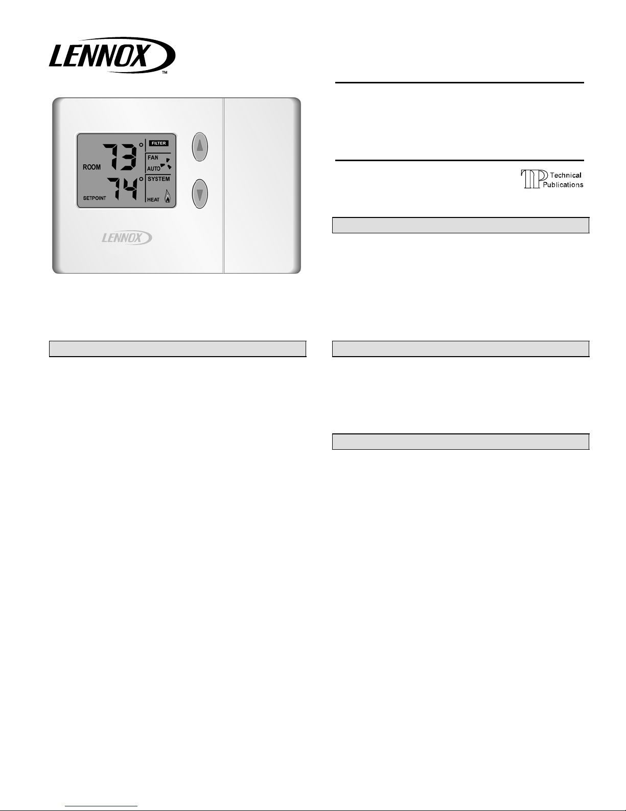
L3011C/L3021H Thermostats
The Lennox ComfortSenset 3000 Series non-programmable electronic thermostats are easy-to-use, have a
large, easy-to-read display, and provide excellent temperature control. Both thermostat models also includes a programmable filter change reminder, and a system check indicator which will notify the user of the need for equipment
service.
Thermostat model L3011C is suitable for non-heat pump,
single−stage heat/single−stage cool applications that are
matched with a gas or electric furnace.
Thermostat model L3021H is suitable for single−stage heat
pump applications that are matched with a gas or electric
furnace as the auxiliary heat source. An optional outdoor
temperature sensor provides auxiliary heat lockout/balance point operation and dual−fuel compatibility.
INSTRUCTIONS
ComfortSenset 3000 Series
Models L3011C/L3021H
Non-Programmable
Thermostats
CONTROLS
506080−01
11/11
Supersedes 02/08
Table of Contents
L3011C /L3021HThermostats 1. . . . . . . . . . . . . . . . . . .
General 1. . . . . . . . . . . . . . . . . . . . . . . . . . . . . . . . . . . . . .
Shipping & Packing 1. . . . . . . . . . . . . . . . . . . . . . . . . . . .
Requirements 2. . . . . . . . . . . . . . . . . . . . . . . . . . . . . . . . .
Installation 2. . . . . . . . . . . . . . . . . . . . . . . . . . . . . . . . . . . .
Thermostat Operation 3. . . . . . . . . . . . . . . . . . . . . . . . . .
DIP Switch Settings 3. . . . . . . . . . . . . . . . . . . . . . . . . . .
Wiring Diagrams 5. . . . . . . . . . . . . . . . . . . . . . . . . . . . . .
General
These instructions are intended as a general guide and do
not supersede local codes in any way. Consult authorities
having jurisdiction before installation.
Check equipment for shipping damage. If you find any
damage, immediately contact the last carrier.
Shipping and Packing List
1 − Thermostat (L3011C or L3021H)
2 − Plastic wall anchors
2 − Screws
Optional Accessories
Outdoor Sensor (used with L3021H only): X2658
Wall Plate: X2659
Litho U.S.A.
11/11 506080−01
*2P1111* *P506080-01*
Page 2
Requirements
IMPORTANT
Read all of the information in this manual before using
this thermostat.
All wiring must conform to local and national building
and electrical codes and ordinances.
This is a 24VAC Class II voltage thermostat. Do not
install on voltages higher than 30VAC.
Be sure that power routed to the thermostat has been powered off before beginning installation.
This thermostat should be used only as described in this
manual.
Do not install the thermostat on outside walls (where there is
unconditioned space on opposite side of wall) or in locations
where direct sunlight may be present.
Install thermostat about 5 feet up from the floor.
CAUTION
Do not short (jumper) across terminals on the gas
valve or at the system control to test installation.
This will damage the thermostat and void the warranty.
Installation
NOTE − If this thermostat is replacing an existing thermostat, carefully label the existing thermostat wires so that
they can be identified later.
1. If a previously-installed thermostat exists, remove it; if
none exists, identify the location for installation (locate,
or install wiring as necessary). To facilitate installation,
enlarge the hole where the thermostat wires protrude
through the wall to about 1−1/2" wide by 3/4" high.
2. Pull about 3 inches of the thermostat wiring through
the wall opening. Strip 1/4" of the insulation from the
ends of the thermostat wires to be used.
3. Use a screwdriver to remove the thermostat subbase
from the body. Carefully pry the subbase away from
the body along the bottom edge of the base near the
two mounting snaps; then lift the subbase upward.
4. Use the subbase as a template to mark the desired
mounting hole locations on the wall.
5. Drill two 3/16" holes at the marked locations on the
wall. Insert the provided plastic wall anchors provided
into the holes. Press the anchors into the holes until
anchors are flush with the wall.
6. Align the subbase over the plastic anchors and secure
it to the wall using the provided screws.
7. Use a small slotted screwdriver to secure all wires to
the subbase terminal block. Make thermostat connections as follows:
D L3011C − See table 1 and figure 1.
D L3021H − See table 2 and figure 2.
8. Thermostat L3021H Only
D For most applications, E will be jumpered to W1. If
separate wires are not provided for both E and
W1, jumper the E terminal to the W1 terminal on
the thermostat subbase.
D For dual−fuel applications (heat pump with gas fur-
nace), OR for auxiliary heat lockout applications,
the optional outdoor sensor (part number X2658)
MUST be installed.
D Connect the outdoor temperature sensor wires to
the T terminals on the subbase terminal strip. (The
sensor connections are not polarity−sensitive.)
9. After wiring is complete, thoroughly seal the hole in the
wall with a suitable material to prevent unconditioned
air in the wall space from entering the thermostat.
10. Set the thermostat DIP switches as required for the
application. See table 3 for DIP switch settings.
11. Carefully attach the thermostat to the subbase by first
engaging the hinges at the top of the unit, then pivoting
the thermostat downward until the thermostat snaps
into place.
The thermostat is now ready for operation. Turn on
power to the thermostat and refer to the appropriate
thermostat operation manual: 504,865M for L3011C
or 504,931M for L3021H.
12. Remove the clear protective film from the face of the
thermostat display.
Note: After this film is removed, some dark streaks or
lines may temporarily appear on the display. These
are normal and should disappear within a few minutes.
Removing Thermostat
The thermostat hinges on tabs on the top of the subbase.
After installation is complete, no tool is needed to remove
the thermostat from the subbase. Pivot the bottom of thethermostat outward (releasing the snaps), then lift up to remove.
Table 1. L3011C Terminal Designations
Terminal Description
R 24VAC
G Fan control
Y1 First stage cooling
W1 First stage heating
L Service Indicator
C 24VAC common
506080−01 11/11
Page 2
Page 3

Table 2. L3021H Terminal Designations
Terminal Description
O Reversing valve, cool active
B Reversing valve, heat active
R 24VAC
G Fan control
Y1 First-stage cooling/heating, compressor-
generated
W1 Auxiliary heating, furnace-generated
L Service Indicator
C 24VAC common
E Emergency heat
T Outdoor temperature sensor connection 1
T Outdoor temperature sensor connection 2
(Wired)
Figure 2. L3021H Terminal Strip
Thermostat Operation
NOTE: The thermostat heating mode will not operate if the
thermostat has been stored or is being used at ambient
temperatures that are above 93°F. The heating function
will be enabled after the thermostat is exposed to ambient
temperatures below 93°F for about 30 minutes.
Figure 1. L3011C Terminal Strip
(Wired)
DIP Switch Settings
DIP Switch Settings
L3011C and L3021H thermostats include five DIP
switches located on the back side of the thermostat body.
These switches may be used to re−calibrate the thermostat
(Cal 1, Cal 2 and Cal±) and to select the thermostat display
(Fahrenheit or Celsius). Thermostats L3011C also include
a DIP switch used to select fan operation for either electric
heat or gas heat applications.
Thermostat L3021H includes a DIP switch used to indicate
whether electric or gas back−up heat will be used. Refer to
table 3 for DIP switch function descriptions.
Page 3
L3011C/L3021H THERMOSTATS
Page 4

Table 3. DIP Switch Function Description
Designation
1 − Cal 1 Room Temperature
2 − Cal 2 Room Temperature
3 − Cal +/− Room Temperature
4 − F/C Select Fahrenheit or
5 − Fan
Option
(L3011C
only)
5 − Backup Heat
(L3021H
only)
Description Off On
Offset: 1°F
Offset: 2°F
Offset: Sign
Celsius Display
Select Heating Fan
Operation:
Electric (E) or
Gas (G)
Select Backup Heat:
Electric (Aux) or
Gas (Dual)
0°F 1°F 0°F
0°F 2°F 0°F
Positive
F C F
G E G
Aux Dual Aux
Negative
Factory
Setting
Positive
Thermostat Calibration
The Cal 1, Cal 2 and Cal± DIP switches may be used to
offset or recalibrate the room temperature display. Table 4
provides DIP switch settings and corresponding temperature offset values.
L3011C Thermostats Only − If the fan operation DIP switch
is set on G, fan operation during the heating mode will be controlled by the furnace, rather than by the thermostat. The
thermostat fan icon is not displayed during heating mode operation, even though the fan may be energized. This setting
is used in applications which include a gas furnace. If the fan
operation DIP switch is set on E, the thermostat controls fan
operation during the heating mode. This setting is used in applications which include an electric furnace.
L3021H Thermostats Only − Restriction of the backup heat
functions requires the installation of the optional outdoor temperature sensor (X2658). The sensor must be wired to the
subbase terminal strip T terminals. Use the backup heat DIP
switch to select either electric heat backup or gas heat backup.
Table 4. DIP Switch Temperature Offset
Cal 1 Cal 2 Cal +/− Temperature Offset
Off Off Off +0°F (no offset)
On Off Off +1°F
Off On Off +2°F
On On Off +3°F
Off Off On −0°F (no offset)
On Off On −1°F
Off On On −2°F
On On On −3°F
506080−01 11/11
Page 4
Page 5

Wiring Diagrams
Typical wiring diagrams for the thermostats are shown in figure 3 for the L3011C and figure 4 (Page 6) for the L3021H.
L3011C
L3011C
NOTE − If the CS3000 is being installed with an icomfort−enabled air handler, refer to
the appropriate Air Handler Installation Instructions for thermostat connections.
L3011C L3011C
AIR HANDLER WITH V" DRIVEAIR HANDLER
FURNACE WITH V" DRIVEFURNACE
Figure 3. Typical Wiring Diagrams for Condenser and L3011C Thermostat
Page 5
L3011C/L3021H THERMOSTATS
Page 6

AIR HANDLER AIR HANDLER WITH V" DRIVE
HEAT PUMP
L3021HL3021H
NOTE − If the CS3000 is being installed with an icomfort−enabled air handler, refer to
the appropriate Air Handler Installation Instructions for thermostat connections.
FURNACE
DUAL FUEL
L3021HL3021H
FURNACE WITH V" DRIVE
Figure 4. Typical Wiring Diagrams for Heat Pump or Dual Fuel with L3021H Thermostat
506080−01 11/11
Page 6
 Loading...