

Page 1

E2017 Lennox Industries Inc.
Dallas, Texas, USA
THIS MANUAL MUST BE LEFT WITH THE OWNER
FOR FUTURE REFERENCE
WARNING
Improper installation, adjustment, alteration, service or
maintenance can cause property damage, personal injury
or loss of life. Installation and service must be performed
by a qualified installer, service agency or the gas supplier
OPERATION MANUAL
C0STAT05FF1L CS3000
Commercial Programmable
Thermostat
CONTROLS
507518-02
5/2017
Supersedes 507518-01
C0STAT05FF1L 5/2 Day Programmable
Thermostat
The Lennox ComfortSense® 3000 Series Commercial
Programmable Thermostat, Model C0STAT05FF1L
(11Y05) is a 5/2 day programmable and 2-heat / 2-cool
electronic thermostat. It includes a programmable filter
change reminder, an equipment maintenance reminder,
and a system check indicator to notify the user when the
equipment requires service.
This thermostat is suitable for 2‐stage heat / 2‐stage cool
applications using a gas or electric auxiliary heat source and
can also be used with an economizer.
Page 2
Page 2
507518-02
The remote indoor sensor when connected and configured
will act as a room temperature sensor instead of internal
temperature sensor available with the thermostat. The dip
switch is used to select either built-in or external remote
indoor temperature sensor used for temperature control.
Table of Contents
5/2 Day Programmable Thermostat 1..............
General 2......................................
Initial Thermostat Power‐up 2.....................
Buttons, Backlight, Timers & Settings 3............
DAY/TIME - Set Day and Time 4..................
HEAT - Heat Mode 4............................
COOL - Cool Mode 5............................
HOLD - Temperature Hold Mode 6................
PROG - Thermostat Programming 7...............
FAN - Controlling Fan Operation 9.................
SETTINGS - Filter and Maintenance Reminders 10...
SETTINGS - Balance Point 11.....................
Service Indicator 12..............................
Thermostat RESET 12............................
Removing/Installing Thermostat 13.................
Default Thermostat Settings 13....................
Technical Specifications 13........................
General
These instructions are intended as a general guide and do
not supersede local codes in any way. Consult authorities
having jurisdiction before installation. Check equipment for
shipping damage. If you find any damage, immediately
contact the last carrier.
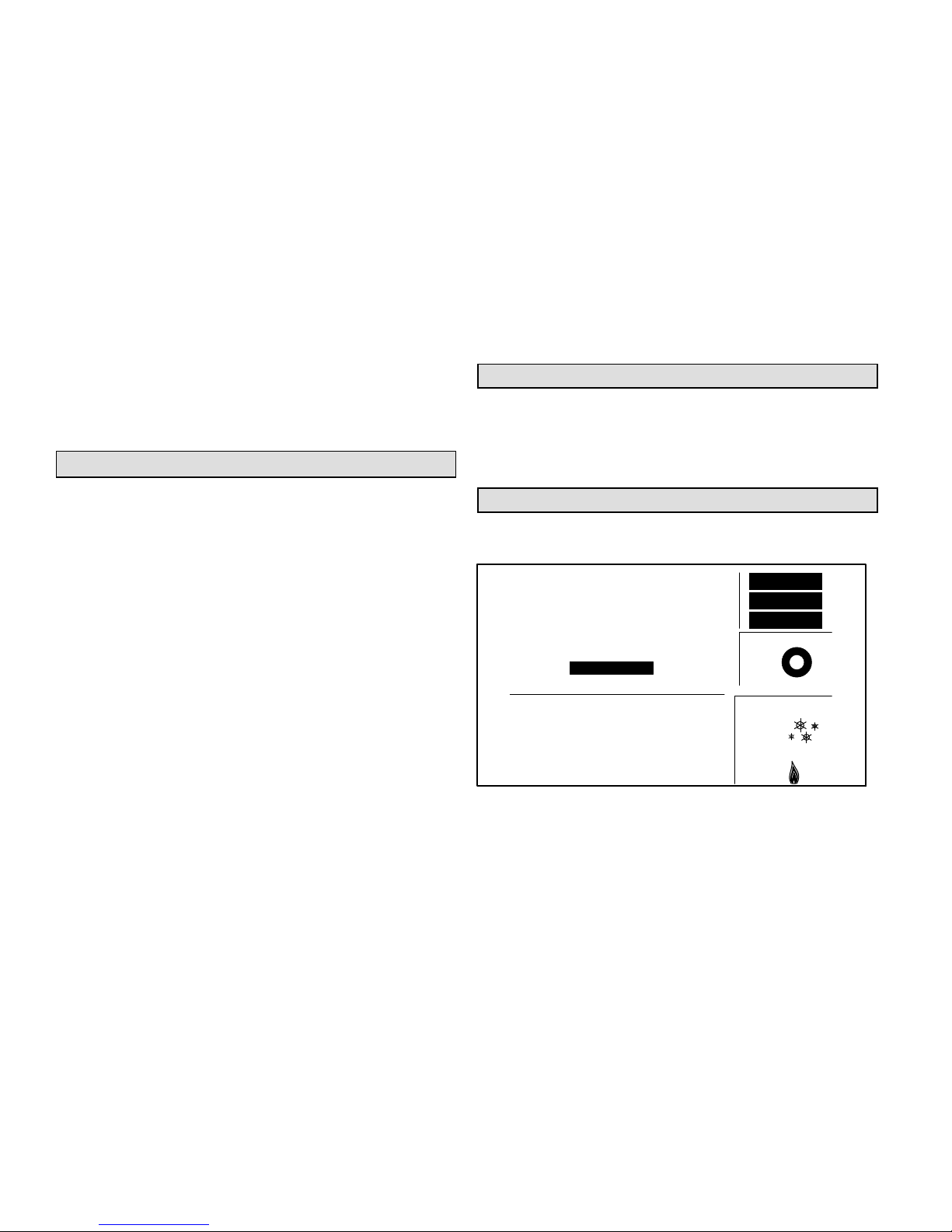
Initial Thermostat Power‐up
When power is initially applied to the thermostat, the display
will appear as shown in figure 1.
FAN
ON
AUTO
SYSTEM
COOL
OFF
HEAT
12:88
88
AM
PM
ROOM
88
MO TU WE TH FR SA SU
SETPOINT
°
°
SERVICE
FILTER
MAINT
Hi
Lo
PROG A | B | C | D HOLD
Figure 1. Initial Power-Up Display
NOTE - Tables 3 on page 13 lists all of the system defaults.
Page 3

Page 3
5/2 DAY PROGRAMMABLE COMMERICAL THERMOSTAT
At this point, the thermostat will be fully functional; its default
temperature set point (not shown) is 70°F. At this point, if the
equipment has been fully powered and if a heat demand
were present, the system would begin operating. UC
indicates unoccupied and OC indicates occupied.
NOTE - Temperature scale default is Fahrenheit units but
may be reset to show Celsius, if desired. See page 14.
Buttons, Backlight, Timers & Settings
Buttons are located behind the small door on the right-hand
side of the thermostat (see figure 2).
Heat
Prog
Fan
Settings
Cool
Day/Time
Hold
Enter
(DOOR
OPEN)
10:36
72
UC
HOLD
AM
PM
ROOM
MO
°
FAN
AUTO
SYSTEM
COOL
Figure 2. Thermostat Buttons
IMPORTANT
Do NOT begin pressing buttons until after you read the fol
lowing section describing each button.
A pale blue display backlight illuminates for 30 seconds
each time any button is pressed.
When PROG or DAY/TIME is pressed, a field begins
flashing, expecting another input. Start making changes
within 15 seconds or the HOME screen will return.
When an Arrow, HOLD, HEAT, or COOL button is pressed,
setpoint and temperature setting appears for 15 seconds. If
desired, start making changes within 15 seconds or the
HOME screen will return. The backlight will turn off 15
seconds after the HOME screen reappears.
WARNING
This product contains a chemical known to the State of
California to cause cancer, birth defects, or other
reproductive harm.
Page 4

Page 4
507518-02
DAY/TIME - Setting the Day and Time
Press the DAY/TIME button and set the CURRENT hour,
minute, and day of week as follows:
1. “AM12” will flash on the screen. Press the up or down
arrows buttons to change the hour. (“AM” or “PM” must
correspond to time of day.) Press DAY/TIME OR, if
adjusting for daylight savings time, pressing ENTER
stores the single change and exits to the HOME screen,
bypassing minutes and day of week.
2. Minutes will flash. Use the up or down arrow buttons to
display the minutes past the hour. Press DAY/TIME.
3. Day “MO” (Monday) will flash. Use up or down arrow
buttons to display the current day. Day selections are
abbreviated as “MO“, “TU”, “WE”, “TH”, “FR”, “SA”, and
“SU”. Press DAY/TIME.
4. The HOME screen reappears; confirm day and time are
correct. This completes day and time setting.
HEAT - Using the Heat Mode
Enabling Normal Heat Mode
Use the HEAT button to enable or disable heat mode. If the
thermostat is in OFF or COOL mode, pressing the Heat
button enables Heat mode. This is indicated by HEAT in the
SYSTEM box as shown in figure 3.
Heat
Prog
Fan
Settings
Cool
Day/Time
Hold
Enter
5:30
UC
70
HOLD
AM
PM
SETPOINT
FAN
AUTO
SYSTEM
HEAT
MO
°
Figure 3. Turn Heat ON/OFF
Disabling Heat Mode
If the thermostat is in heat mode when the HEAT button is
pressed, then heat mode is disabled. This is indicated by
OFF in the SYSTEM box as shown in figure 4.
SYSTEM
COOL
OFF
75
ROOM
UC
°
Figure 4. Heat Mode Disabled
Page 5

Page 5
5/2 DAY PROGRAMMABLE COMMERICAL THERMOSTAT
Heating Demand
The thermostat must be in heat mode in order to properly
control the heating equipment. In heat mode, when the
actual temperature is lower than the temperature set point
the thermostat detects a heating demand and activates the
heating equipment to satisfy the demand. Heating operation
is indicated by a flame icon in the SYSTEM box.
When the actual temperature rises above the temperature
setpoint, the flame icon will disappear. This indicates that
the heating demand has been satisfied and that the heating
equipment has been turned off.
There are two timers govern the restart of heating:
1. Minimum furnace off timer (1.5 minutes only for HG).
2. Minimum cycle timer (six minutes).
For example:
If heating has been on for over six minutes then minimum
cycle timer is already fulfilled. For HG (gas), it will restart
after 1.5 minutes. For HE (electric), it will restart
immediately.
If the heating has not been on for six minutes, it will make up
the six minutes during the off time. Therefore the lock out
time is never six minutes.
COOL - Using the Cool Mode
Enabling and Disabling Cool Mode
Use the COOL button to enable or disable cool mode as
desired. If the thermostat is in HEAT or OFF mode, cool
mode is enabled when the COOL button is pressed. This is
indicated by COOL in the SYSTEM box (see figure 5).
10:30
UC
70
HOLD
AM
PM
SETPOINT
MO
°
°
Heat
Prog
Fan
Settings
Cool
Day/Time
Hold
Enter
FAN
ON
SYSTEM
COOL
Figure 5. Turn Cool ON/OFF
Page 6

Page 6
507518-02
If the thermostat is in cool mode, pressing the COOL button
disables COOL mode (indicated by OFF in the SYSTEM
box - see figure 6).
SYSTEM
COOL
OFF
HEAT
75
ROOM
°
OC
Figure 6. Cool Mode Disabled
Cooling Demand
Set the thermostat to cool mode to control the cooling
equipment. Then, if the room temperature is higher than the
temperature setpoint, the thermostat detects a cooling
demand and will activate the cooling equipment to satisfy
the demand.
75
ROOM
°
OC
SYSTEM
COOL
OFF
HEAT
HI
Figure 7. Cooling Demand
Cooling operation is indicated by flashing “snowflake” icons
in the SYSTEM box. When the actual temperature drops
below the temperature setpoint, the snowflake icons will
disappear. This indicates that the cooling demand has been
satisfied and that the cooling equipment has been turned
off.
If a large cooling demand is present, ”Hi” will be displayed in
the SYSTEM box (shown in figure 7).
NOTE - If no buttons are pressed during a demand for
cooling, the equipment must operate for at least four
minutes. After a demand has been satisfied, cooling
equipment operation is locked out for five minutes. If
another cooling demand occurs during this 5-minute
interval, “COOL” and the snowflakes will flash; however, the
cooling equipment will not operate until the 5-minute delay
has elapsed.
HOLD - Using Temperature Hold Modes
When HOLD is displayed on the HOME screen, the
thermostat is in a temperature hold condition. This means
that the temperature program data is ignored and the
thermostat functions much like a non-programmable
thermostat.
Adjusting Temperature Setpoint in Hold Mode
The temperature setpoint represents the desired
temperature of the space around the thermostat.
To adjust the setpoint, press the up or down (YB) arrow
buttons the existing setpoint is displayed to the right of the
Page 7

Page 7
5/2 DAY PROGRAMMABLE COMMERICAL THERMOSTAT
occupancy mode. Each button press adjusts the setpoint up
or down by 1 degree.
Heat
Prog
Fan
Settings
Cool
Hold
Enter
Day/Time
10:36
72
UC
HOLD
AM
PM
ROOM
MO
°
FAN
AUTO
SYSTEM
COOL
Figure 8. Hold Temperature Mode
After the desired setpoint is reached, the HOME screen will
reappear after about 15 seconds (see figure 8).
Permanent Hold Mode
At any time the program is running, from the HOME screen,
set a permanent hold (program override) by pressing the
HOLD button (see figure 8). The thermostat now functions
much like a non-programmable thermostat. Use the
Up/Down arrow buttons to adjust the hold set point. To
return to the program, press HOLD again. The occupancy
status will remain unchanged in permanent hold mode.
Temporary (2‐Hour) Hold
At any time the program is running, from the HOME screen,
set a temporary 2‐hour hold by pressing the up or down
arrow buttons until the desired set point is displayed;
“HOLD” flashes (see figure 9). This overrides the program
for 2 hours from the last button press, then returns to the
program.
To change occupancy status in temporary hold mode, press
the ENTER button while HOLD indicator flashes. The
occupancy can be set to OC (occupied) / UC (unoccupied)
by pressing the ENTER button.
Heat
Prog
Fan
Settings
Cool
Hold
Enter
Day/Time
10:36
72
UC
AM
PM
ROOM
MO
°
FAN
AUTO
SYSTEM
COOL
PROG B HOLD
Figure 9. Temporary Hold Temperature Mode
While in Temporary Hold, press HOLD once to switch to
Permanent Hold (HOLD displays solid; PROG not
displayed); press HOLD again to return to the program
(PROG displays; HOLD not displayed).
PROG - Thermostat Programming
The thermostat can be programmed to perform a set of
either heating or cooling events (but not a combination of
Page 8

Page 8
507518-02
heat and cool) for five consecutive days using a set of four
unique events per day. The remaining two days can then be
set for a different set of four unique events per day. Both the
consecutive days and the events/temperature are set by the
user.
To Change Consecutive Days...
To alter the five consecutive days, press and hold the
PROG button for three seconds. The five consecutive day
period is then displayed (default is MOnday thru FRiday). To
change to a different 5‐consecutive days, use the up or
down arrow buttons. Any five consecutive-day span may be
selected, for example, in figure 10, Saturday through
Wednesday is defined as the 5-day programming
(Thursday and Friday would constitute the 2-day
programming). Press the PROG button when finished.
FILTER
MO TU WE TH FR SA SU
Figure 10. Change Consecutive days
To Set Program Events and Temperatures...
Figure 11 gives an example of how the two sets of programs
can be set for a normal workweek and weekend.
In the 5-day bar graph, note how programs A and C reflect
the desired warmth while the location IS occupied (72°); B
allows less heating while the location is NOT occupied; D
reflects a cooler sleeping temperature. The 2-day bar graph
would support day-long occupancy and, because the first
program begins later, a less-demanding time schedule.
5-DAY PROGRAM:
72°
68°
64°
|A | B | C | D |
2-DAY PROGRAM:
72°
68°
64°
|A| B | C | D |
6AM NOON 6PM MID 6AM
NIGHT
6AM NOON 6PM MID 6AM
NIGHT
Figure 11. 5/2 Day Program Example
NOTE - Pressing ENTER during the following programming
steps, saves and exits to the HOME screen.
To program events and temperatures, perform the following
steps, once with Cool selected and once with Heat selected.
1. Press either the HEAT or COOL button.
2. Press and release PROG. “AM 6:00”, period “A”, and the
5 consecutive days are displayed; “AM 6” flashes.
3. Use the up or down arrow buttons to select the desired
hour; press PROG when the desired hour is reached.
4. Use the up or down arrow buttons to select the desired
minute; press PROG.
Page 9

Page 9
5/2 DAY PROGRAMMABLE COMMERICAL THERMOSTAT
5. Use the up or down arrow buttons to select either uc
(unoccupied) or oc (occupied) minute; press PROG.
6. Use the up or down arrow buttons to select the desired
temperature set point; press PROG.
7. Repeat steps 3 through 6 for periods B, C, and D.
8. Repeat steps 1 through 7 for the 2-day program.
NOTE - This thermostat will NOT automatically switch from
heating to cooling, or cooling to heating; operator
involvement is required. At the change of seasons, or to
accommodate abnormal seasonal temperature swings, you
must manually select to the opposite conditioning (Heat or
Cool) program.
FAN - Controlling the Fan Operation
Use the FAN button to select either continuous fan mode or
auto fan mode.
To change from continuous to auto fan mode or back to
continuous, press the FAN button. Note whether a fan icon
in the FAN box is present (indicating that the fan is running)
or not (fan not running).
If continuous fan mode is enabled (ON displayed in FAN box
- see figure 12), the fan will run continuously regardless of
whether the heating or cooling equipment is running.
Heat
Prog
Fan
Settings
Cool
Hold
Enter
Day/Time
10:10
67
PROG B
AM
PM
ROOM
FAN
ON
SYSTEM
HEAT
MO
°
UC
Figure 12. Using Fan ON
If auto fan mode is selected (AUTO displayed in FAN box see figure 13), the fan will only run when the heating or
cooling equipment is running.
Heat
Prog
Fan
Settings
Cool
Hold
Enter
Day/Time
10:36
72
AM
PM
ROOM
MO
°
FAN
AUTO
SYSTEM
OFF
PROG B
UC
Figure 13. Using Fan AUTO
Page 10

Page 10
507518-02
SETTINGS - Filter/Maintenance Reminders
The thermostat is designed to remind you when the filter
needs changing or when routine maintenance is required,
as (and if) defined, by you. These optional reminders are not
enabled until you activate them. To do so, press the
SETTINGS button (shown below the Fan button in figure
13) once or twice for the desired reminder as shown in figure
14 and as described in table 1.
FILTER
off
MAINT
For FILTER,
press Settings
button 1 time
For MAINT,
press Settings
button 2 times
Figure 14. Reminder Settings Display
The default setting for the reminders is OFF (disabled).
Press either the up or down arrow buttons to select the
desired reminder intervals.
Table 1. Filter and Maintenance Reminders
Buttons to
Use
Reminder
Available Settings and How
to Use
Settings
(1st press)
then Arrows
to scroll
selections
FILTER
Total fan run time expressed in
months (Off, 1, 3, 6, 12); for
example, if fan runs 12 hours a
day, 1 month reminder displays
in 2 calendar months.
Settings
(2nd press)
then Arrows
to scroll
selections
MAINT
Elapsed chronological time in
months (Off, 6, 12). Use this, for
example, to remind yourself
when to perform routine checks
or when to call a technician for
periodic preventive
maintenance.
Enter Stores settings.
NOTE - The HOME screen will reappear about 15 seconds
after the final arrow button press. OR, press ENTER at any
time to store any changes and exit to the HOME screen.
After either programmed interval has elapsed, the reminder
will be displayed as shown in figure 15.
Page 11

Page 11
5/2 DAY PROGRAMMABLE COMMERICAL THERMOSTAT
10:i2
PROG A B C D HOLD
FAN
ON
AUTO
SYSTEM
COOL
OFF
HEAT
78
ROOM
SERVICE
°
FILTER
AM
PM
MO TU WE TH FR SA SU
MAINT
UC
Figure 15. Reminders
After the filter has been changed or maintenance
performed, reset the reminder by pressing the SETTINGS
button for four seconds. The screen will blink for a few
moments to indicate that the timer has been reset.
Internal/Remote Sensor
If the optional Remote Indoor Sensor (10K) (47W37) is
connected and configured it will serve as a room
temperature sensor instead of using the internal
temperature sensor built into the thermostat. The dip switch
(position #4) is used to select either built-in or external
remote indoor temperature sensor used for temperature
control.
Occupied and Unoccupied Modes
During permanent hold mode the occupancy output follows
the program. During two hour hold mode the user can
change the occupancy status by pressing the enter button.
The occupancy status will be changed to occupied OC or
Unoccupied UC alternatively by pressing the enter button.
The occupancy relay is turned on when the user selected
the occupancy status during programming. The default
state of the occupancy relay is off. The occupancy relay will
turn on the economizer in the system
Table 2. Thermostat Outputs (Occupancy)
Demand Condition
W1 W2 OC Y1 Y2 G
Cooling Demands with Occupancy
First Stage Cooling X X X
Second Stage Cooling X X X X
No Demand - Continuous mode X X
No Demand - Auto mode X
Heating Demands with Occupancy
First Stage Heating X X X
Second Stage heating X X X X
No Demand - Continuous mode X X
No Demand - Auto mode X X
Page 12

Page 12
507518-02
Service Indicator
When abnormal equipment operation is detected, the
SERVICE indicator will flash on the screen (see figure 16).
This indicates that the equipment requires service from a
qualified service technician.
10:14
PROG A B C D HOLD
79
ROOM
SERVICE
°
FILTER
AM
PM
FAN
ON
AUTO
SYSTEM
COOL
OFF
HEAT
MO TU WE TH FR SA SU
UC
Figure 16. Service Indicator Flashing
Thermostat RESET
Under some abnormal conditions, it may be necessary to
“reset” the thermostat to its default condition. Such a
RESET would delete all programming and settings and
therefore should only be used on rare occasions when the
the thermostat fails to function as designed and/or as
programmed. Such an instance can occur as a result of a
power surge or similar electrical disturbance (e.g. after an
electrical storm or power outage). The RESET button can
be used to recover from this situation.
Heat
Prog
Fan
Settings
Cool
Day/Time
Hold
Enter
(DOOR
OPEN)
10:36
72
UC
HOLD
AM
PM
ROOM
MO
°
FAN
AUTO
SYSTEM
COOL
Figure 17. Reset Button
CAUTION
When the RESET button is pressed, ALL settings revert
back to the their defaults (see tables 3 on page 13.
The RESET button is an unlabeled, recessed button located
behind the door, on the right-hand side of the thermostat,
Page 13

Page 13
5/2 DAY PROGRAMMABLE COMMERICAL THERMOSTAT
below the SETTINGS button (see figure 17). Use a paper
clip or small pencil to press the RESET button; ALL
thermostat settings will be reset to the defaults listed in the
Default Thermostat Settings section.
Removing/Installing Thermostat
The thermostat hinges on tabs on the top of the sub-base;
no tool is needed to remove the thermostat from the
sub-base. Pivot the bottom of the thermostat outward
(releasing the snaps), then lift up to remove.
To replace it, first position the top tilted toward the wall
bracket and align it until you feel the tabs and slots engage;
then, while the top is in place, pivot the bottom toward the
wall until the thermostat snaps into place.
Default Thermostat Settings
Default thermostat settings are shown in table 3.
Table 3. Default Thermostat Settings
Mode Heat (Permanent Hold Mode)
Setpoint 70°F (or 21°C)
Fan Auto
Filter Reminder OFF
Maintenance Reminder OFF
Equipment Protection Timers Reset Back to Zero
Technical Specifications
Thermostat Type
Electronic programmable thermostat for non-heat pump,
2‐stage heat / 2‐stage cool.
Power Supply Range
18VAC - 30VAC (24VAC nominal), 50Hz1 or 60Hz
1
When the thermostat is used in 50Hz applications, the
tolerance will be lowered leading to slight change in
temperature control accuracy.
CAUTION
24VAC is present on the terminals of the thermostat
bracket. If removing the thermostat from the wall, use cau
tion and avoid touching any of the connector terminals on
the wall bracket.
Also, when working with the thermostat dip switches, use
a non-conductive tool and take caution to avoid making
any contact with the circuit board, its imprinted circuitry
and its connector prongs.
Temperature Display
S Display Scale: Fahrenheit or Celsius user selectable
S Display range: 35°F (2°C) to 99°F (37°C)
S Display resolution: 1°F (1°C)
S Display Accuracy: +/-1°F
Page 14

Page 14
507518-02
Setting Temperature Scale
To select either Fahrenheit or Celsius, press Settings
button three times. Press up/down arrows to toggle
between Fahrenheit and Celsius. Once selected, press
Settings button to exit.
Selecting Internal or Remote Sensor
To select between the internal or remove temperature
sensor use dip switch #4. Factor default setting is set to
internal sensor (OFF)
I/R (internal/remote switch
1
2
3
4
5
6
PLUG IN (Use Care To Avoid Bending Prongs.)
Figure 18. Internal/Remote Sensor Settings
Temperature Measurement Range
S Measurement Scale: Fahrenheit
S Measurement Range: 35°F to 99°F
S Measurement Resolution: 0.125°F
S Measurement Accuracy: +/-1°F
S Field Offset: via DIP switches to +/-3°F
Sampling Method: Tetemperature measurements
sampled every two seconds. Displayed temperature is the
average of the last four measurements.
Temperature Set Point Range
S Setting range: 50°F (10°C) to 90°F (32°C)
S Setting resolution: 1°F (1°C)
Smooth Setback Recovery (via DIP switch #6)
Smooth Setback Recovery (SSR) affects the way the
thermostat responds to program events. If SSR is disabled,
the thermostat will react to a program event at the time the
event occurs. However, if SSR is enabled, the thermostat
will react to a program event before the event occurs such
that the desired temperature is reached at the time of the
event, not after.
Fan Control
AUTO or ON modes.
I/O Relays
All thermostat relays are latching type to minimize power
consumption.
Page 15

Page 15
5/2 DAY PROGRAMMABLE COMMERICAL THERMOSTAT
Table 4. Terminal Designations
Terminal Description
R 24VAC
Y1 Compressor Stage 1 cooling
W1 Stage 1 heating
Y2 Compressor Stage 2 cooling
W2 Stage 2 heating
G Fan
L Service indicator
C Common 24VAC
T Remote Temperature Sensor connection 2
T Remote Temperature Sensor connection 2
OC Occupancy output (economizer)
Equipment Protection Timers
Minimum Compressor OFF time: 5 minutes
Minimum Compressor ON time: 4 minutes
Minimum Electric Heat ON time: 3 minutes
Minimum Furnace ON time: 3 minutes
Minimum Furnace OFF time:1-1/2 minutes
Minimum cycle time (applies to both furnace cycle and
elapsed time) between any furnace activation and the next
furnace activation): 6 minutes.
Minimum elapsed time between any compressor activation
and the next compressor activation: 6 minutes.
NOTE - All protection timers (except the compressor OFF
timer) can be over-ridden if a heating or cooling demand is
initiated or terminated using the UP, DOWN, HEAT, or
COOL buttons.
Equipment Protection Override
Both the minimum compressor OFF timer and the minimum
equipment cycle timer can be over-ridden by pressing and
holding either the HEAT or COOL button down for four
seconds.
Filter Reminder
Settings of Off, 1, 3, 6 or 12 (months of fan run time) are
available. When programmed time has elapsed, a FILTER
indicator is displayed.
Maintenance Reminder
Settings of Off, 6 or 12 (months of chronological time) are
available. When programmed time has elapsed, a
maintenance indicator “MAINT” is displayed.
Page 16

Page 16
507518-02
Service Reminder
The SERVICE indicator is displayed only under the
following conditions:
S if the thermostat Y1 terminal has been activated with
24VAC for at least 5 minutes, AND the L terminal is
shorted to the R terminal;
OR
S if the thermostat Y1 terminal has been activated with
24VAC for at least 5 minutes, AND the L terminal is
shorted to the C terminal.
Power Loss/Recovery
Thermostat memory is retained for a minimum of 24 hours
during a power loss (includes retention of program
information, HOLD status, programmed temperature set
point, heat/cool and fan mode settings, filter reminder
status, maintenance reminder status, and equipment
protection timers). After 24 hours of power loss,
programmed settings will be lost and replaced with default
settings.
IMPORTANT
Power must be applied for at least six consecutive hours
prior to a power loss in order for memory to be retained for
the specified time.
LCD Back Light
Activated for 30 seconds when any button is pressed.
NOTE - During an electrical storm or similar disturbance,
the back light may activate for a few seconds. This is normal
and will no longer occur after the electrical disturbance has
passed.
Thermostat Operating Conditions
32°F to 122°F, 10% to 90% RH
Thermostat Storage Conditions
-40°F to 176°F, 10% to 90% RH
 Loading...