

Lennox COMFORT Installation Manual
Providing indoor climate comfort
COMFORT - Sizes 12-48
COMFORT-IOM-0106-E
Installation manual


1
CONTENT
1. PRECAUTIONS .........................................................................................2
2. INSTALLATION INFORMATION ............................................................... 3
3. ATTACHED FITTINGS...............................................................................4
4. INSTALLATION PLACE ............................................................................ 5
5. INDOOR UNIT INSTALLATION................................................................. 6
6. OUTDOOR UNIT INSTALLATION........................................................... 12
7. INSTALL THE CONNECTING PIPE ........................................................13
8. CONNECT THE DRAIN PIPE .................................................................. 16
9. INSTALLATION OF FLANGE AND DUCT.............................................. 17
10. WIRING ..................................................................................................19
11. TEST OPERATION ................................................................................ 27

2
1. PRECAUTIONS
SAFETY CONSIDERATIONS
Installation and servicing of air conditioning equipment can be hazardous due to system pressure and
electric components. Only trained and qualified service personnel should install, repair or service air
conditioning equipment.
All other operations should be performed by trained service personnel. When working on air
conditioning equipment, observe precautions in the literature, tags and labels attached to the unit and
other safety precautions that may apply. Follow all safety codes. Wear glasses and work gloves. Use
quenching cloth for brazing and unbrazing operations. There are fire extinguishers available for all
brazing operations.
WARNING
This manual describes the installation of specified indoor and outdoor units. Do not install them
connected with any other indoor or outdoor unit .Mismatching of units and incompatibility between
control devices in the two units could lead to damage of both units .
WARNING
Before performing service or maintenance operations on system, turn off main power switch of the unit.
Electrical shock could cause personal injury.
This unit shall be installed in accordance with national wiring regulations.
WARNING
If the supply cord is damaged, it must be replaced by the manufacturer or its service agent or similarly
qualified person in order to avoid a hazard.
The means for disconnection from the supply having a contact separation of at least 3 mm in all poles.
CAUTION
1. Wire the outdoor unit, then wire the indoor unit. You are not allow to connect the air conditioner with
the power source until wiring and piping the air conditioner is done.
2. For installation of the indoor unit, outdoor unit, and connection piping in between, follow the
instructions given in this manual as strictly as possible.
3. Installation in the following places may cause trouble. If it is unavoidable using in such places,
please consult with the dealer.
(1) A place full of machine oil.
(2) A saline place such as coast.
(3) Hot-spring resort.
(4) A place full of sulfide gas.
(5) A place where there are high frequency machines such as wireless installation, welding
machine, medical facilities.
(6) A place of special environmental conditions.
4. Don't install this unit in the laundry.
3
NOTE
Remark per EMC Directive 89/336/EEC
For to prevent flicker impressions during the start of the compressor (technical process), following
installation conditions do apply.
1. The power connection for the air conditioner has to be done at the main power distribution. The
distribution has to be of a low impedance, normally the required impedance reaches at a 32 A fusing
point.
2. No other equipment has to be connected with this power line.
3. For detailed installation acceptance please refer to your contract with the power supplier, if
restrictions do apply for products like washing machines, air conditioners or electrical ovens.
4. For power details of the air conditioner refer to the rating plate of the product.
5. For any question contact your local dealer.
2. INSTALLATION INFORMATION
• To install properly, please read this "installation manual" at first.
• The air conditioner must be installed by qualified persons.
• When installing the indoor unit or its tubing, please follow this manual as strictly as possible.
• When all the installation work is finished, please turn on the power only after a thorough check.
• Regret for no further announcement if there is any change of this manual caused by product
improvement.
CAUTIONS FOR THE REMOTE CONTROLLER OPERATION
• Please do not throw the remote controller or beat it.
• Please use the remote controller within the allowed distance, and keep the transmitter toward the
receiver of the indoor unit.
• Please keep the remote controller more than 1m away from TV or stereo set.
• Never put the remote controller at the place with humid or direct sunlight, or near heaters.
• Please insert the batteries properly.
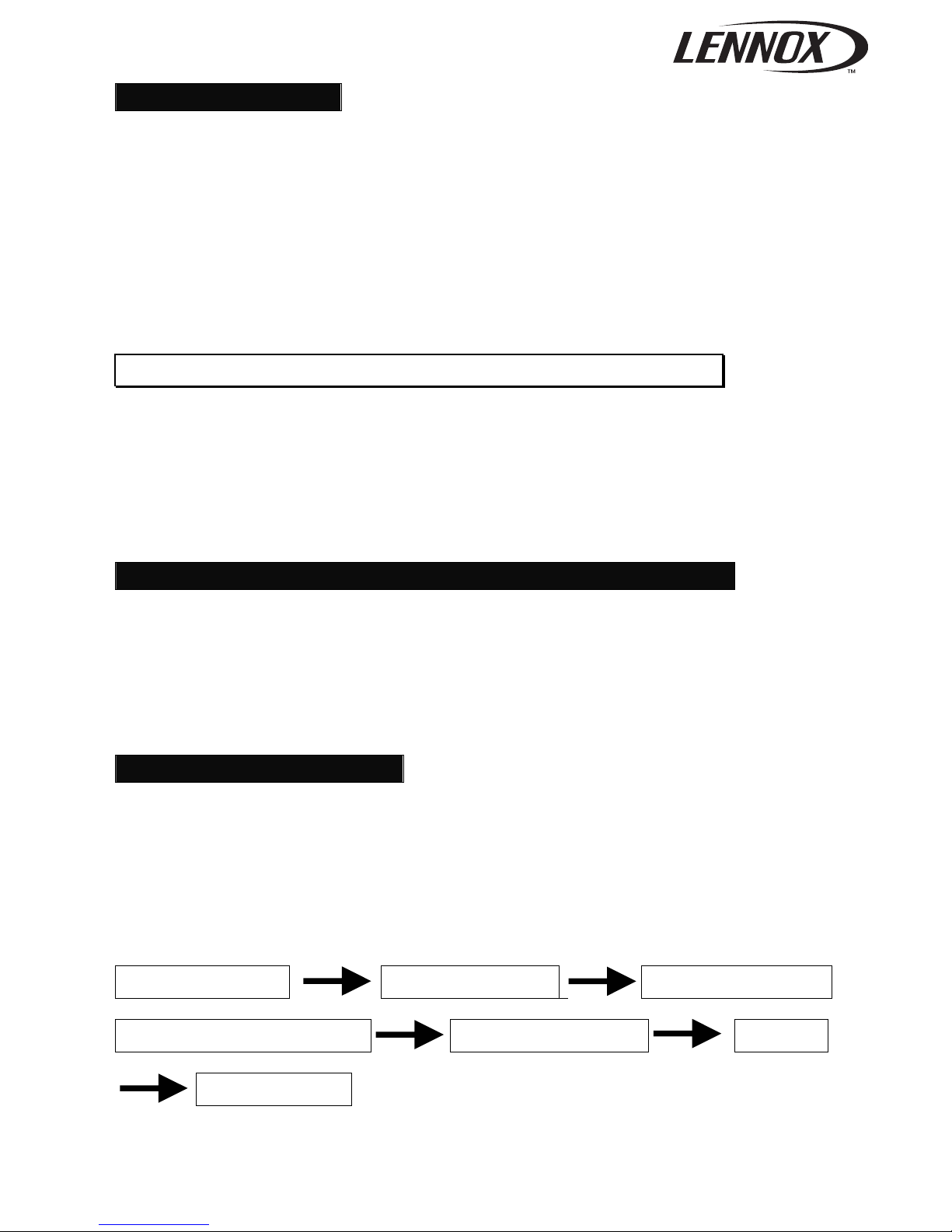
INSTALLATION ORDER
1. Select the location;
2. Install the indoor unit;
3. Install the outdoor unit;
4. Install the connecting pipe;
5. Connect the drain pipe;
6. Wiring;
7. Test operation.
Select the location Install the indoor unit Install the outdoor unit
Install the connecting pipe Connect the drain pipe Wiring
Test operation
4
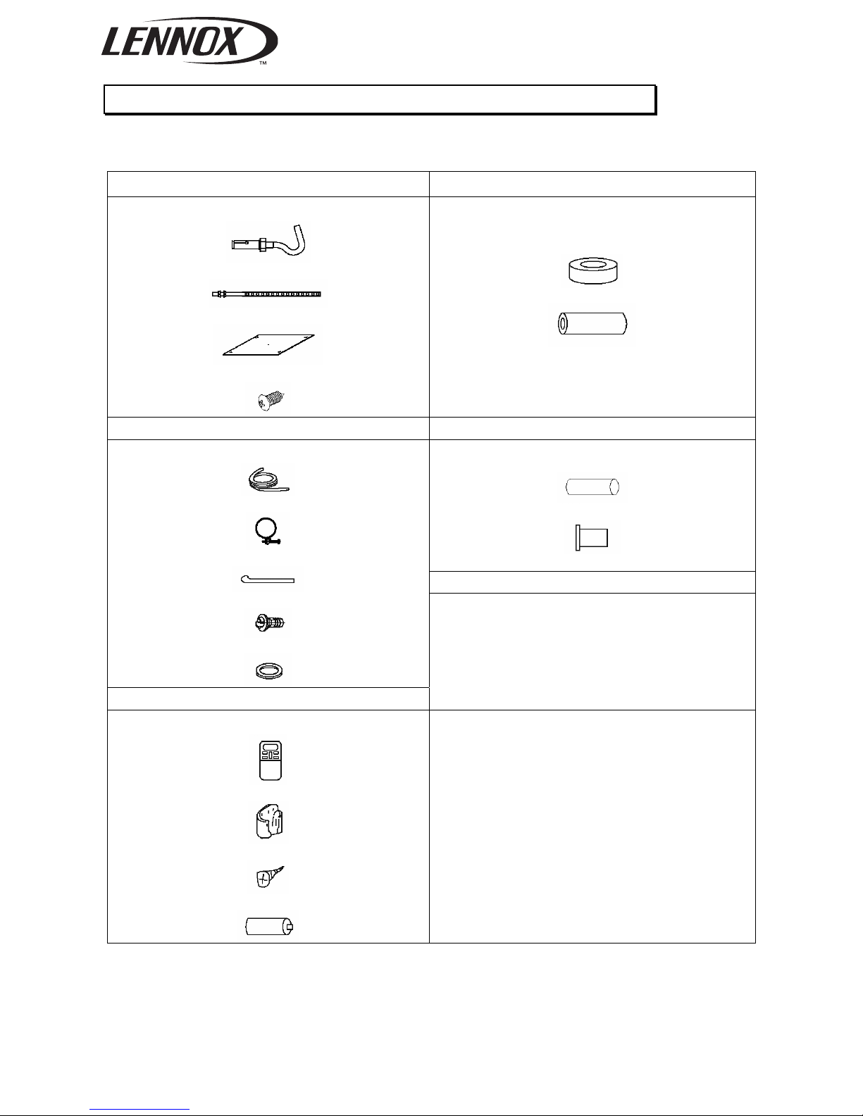
3. ATTACHED FITTINGS
Please check whether the following fittings are of full scope. If there are some attached fittings free from
use, please restore them carefully.
Installation Fittings Tubing & Fittings
1. Expansible hook......................................... 4
2. Installation hook......................................... 4
3. Installation paper board ............................. 1
4. Bolt M5 X 16 or M6 X 12............................ 4
5. Connecting pipe group ...............................1
6. Binding tape................................................6
7. Soundproof / insulation sheath...................2
Drainpipe Fittings Protect Pipe Fittings
13. Wall conduit..............................................1
14. Wall conduit cover ....................................1
Others
8. Out-let pipe sheath..................................... 1
9. Out-let pipe clasp....................................... 1
10. Tightening band ..................................... 20
11. Drain elbow .............................................. 1
12. Seal ring................................................... 1
Remote controller & Its Frame
19. Owner's manual........................................1
20. Installation manual....................................1
15. Remote controller..................................... 1
16. Frame....................................................... 1
17. Mounting screw (ST2.9 x 10-C-H) ........... 2
18. Alkaline dry batteries (AM4)..................... 2

5
4. INSTALLATION PLACE
CAUTION
Location in the following places may cause malfunction of the machine. (If unavoidable, please consult
your local dealer)
a. There is petrolatum existing.
b. There is salty air surrounding (near the coast).
c. There is caustic gas (the sulfide, for example) existing in the air (near a hot spring).
d. The Volt vibrates violently (in the factories).
e. In buses or cabinets.
f. In kitchen where it is full of oil gas.
g. There is strong electromagnetic wave existing.
h. There are inflammable materials or gas.
i. There is acid or alkaline liquid evaporating.
j. Other special conditions.
NOTICES BEFORE INSTALLATION
1. Select the correct carry-in path.
2. Move this unit as originally packaged as possible.
3. If the air conditioner is installed on a metal part of the building, it must be electrically insulated
according to the relevant standards to electrical appliances.
1. The indoor unit
•
There is enough room for installation and maintenance.
• The ceiling is horizontal, and its structure can endure the weight of the indoor unit.
• The air outlet and the air inlet are not impeded, and the influence of external air is the least.
• The air flow can reach throughout the room.
• The connecting pipe and drainpipe could be extracted out easily.
• There is no direct radiation from heaters.
2. The outdoor unit
•
There is enough room for installation and maintenance.
• The air outlet and the air inlet are not impeded, and can not be reached by strong wind. It must be a dry
and well ventilating place.
• The support is flat and horizontal and can stand the weight of the outdoor unit. And will no additional
noise or vibration.
• Your neighborhood will not feel uncomfortable with the noise or expelled air. There is no leakage of
combustible air.
• It is easy to install the connecting pipe or cables.
• Determine the air outlet direction where the discharged air is not blocked.
• A place free of a leakage of combustible gases.
• In the case that the installation place is exposed to a strong wind such as a seaside or high position,
secure the normal fan operation by putting the unit lengthwise along the wall or using a duct or shield
plates.
• If possible, do not install the unit where it is exposed to direct sunlight.
• If necessary, install a blind that does not interfere with the air flow.
• During the heating mode, the water drained off the outdoor unit.The condensate should be well drained
away by the drain hole to an appropriate place, so as not to interfere other people or public.
• Select the position where it will not be subject to snow drifts, accumulation of leaves or other seasonal
debris. It is important that the air flow for the outdoor unit is not impeded as this will result in reduction in
heating or cooling performance.
6
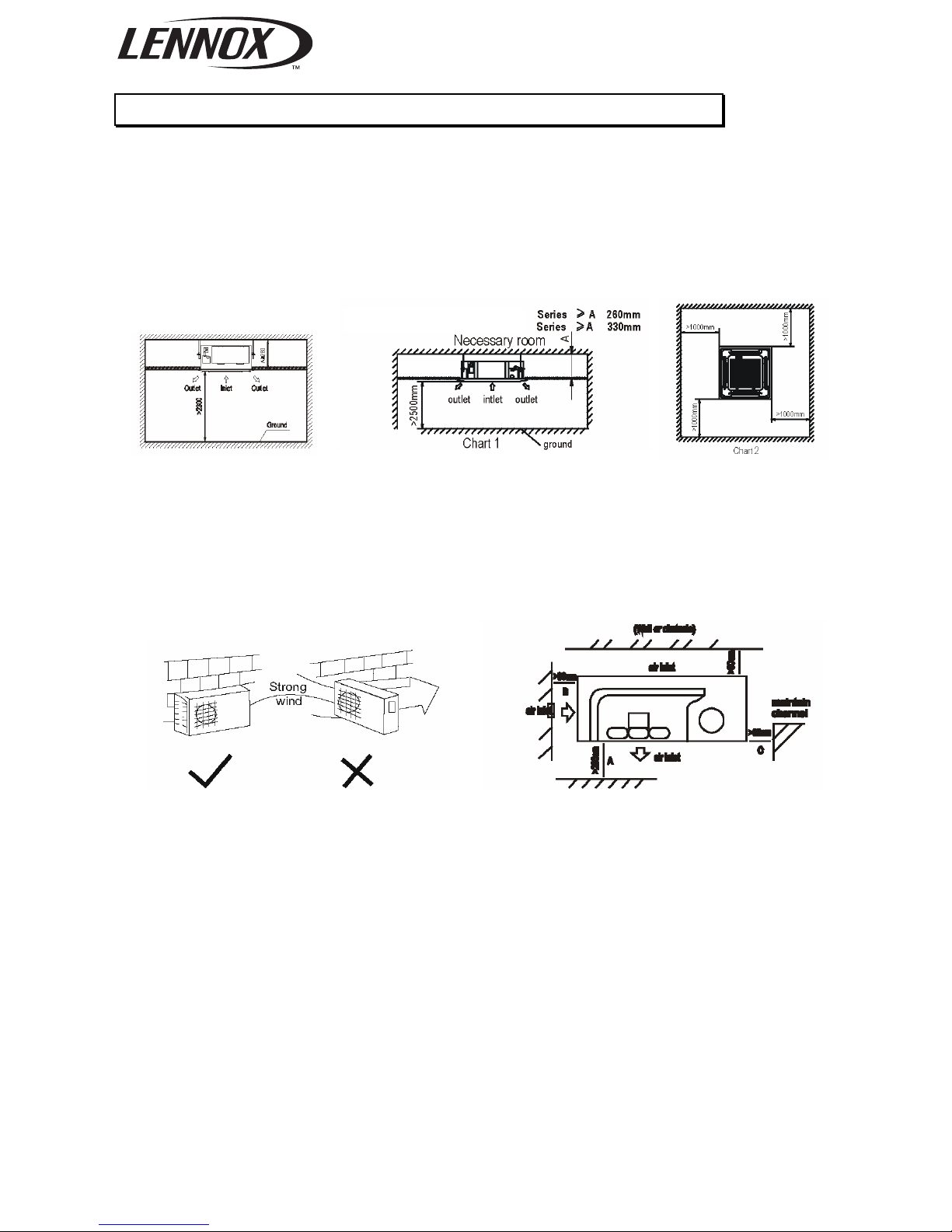
5. INDOOR UNIT INSTALLATION
1. Installation place
•
A place where there is enough room for installation and maintenance.(Refer to Chart 1)
• The ceiling is structurally sound to hold the Indoor Unit.
• A place that is well ventilated and the influence of weather is the least.
• A place that the airflow can reach every corners of the room.
• A place where the drain pipe can reach out easily.
Necessary room
MODEL 12-18(600x600)
• Install the outdoor unit on a rigid base to prevent increasing noise level and vibration.
• Determine the air outlet direction where the discharged air is not blocked.
• In the case that the installation place is exposed to strong wind such as a seaside or high position,
secure the normal fan operation by putting the unit length wise along the wall or using a duct or
shield plates.
• Specially in windy area, install the unit to prevent the admission of wind.
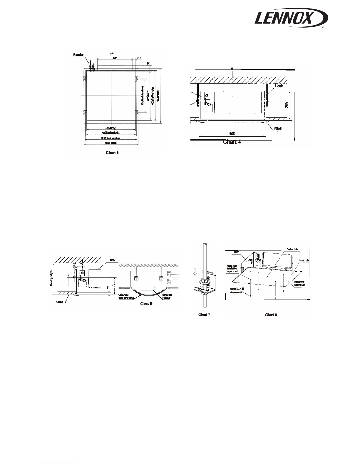
2. Indoor unit installation Model 12-18(600x600)
(1) Install the main body
A. The existing ceiling (to be horizontal)
a. Please cut a quadrangular hole of 600X600mm in the ceiling according to the shape of the
installation paper board.
The center of the hole should be at the same position of that of the air conditioner body.
Determine the lengths and outlets of the connecting pipe, drain pipe and cables.
To balance the ceiling and to avoid vibration, please enforce the ceiling when necessary.
b. Please select the position of installation hooks according to the hook holes on the installation board.
Drill four holes of 12mm, 50~55mm deep at the selected positions on the ceiling. Then embed the
expansible hooks (fittings).
Face the concave side of the installation hooks toward the expansible hooks. Determine the length
of the installation hooks from the height of ceiling, then cut off the unnecessary part.
If the ceiling is extremely high, please determine the length of the installation hook according to facts.
Cut the installation hook open in the middle position, then use appropriate length of reinforcing rod
(φ12) to weld together.
Model 18, 24, 30, 36, 48
7
The length could be calculated from Chart5:
Length = 210+L (in general, L is half of the whole length of the installation hook)
c. Please adjust the hexangular nuts on the four installation hooks evenly, to ensure the balance of the
body.
Use the transparent hose filled with water to check the lever of the main body from the four sides or
diagonal line direction, the lever indicator also can check the lever from four sides of the main body.
(Refer to chart 6)
If the drainpipe is awry, leakage will be caused by the malfunction of the water-level switch.
Adjust the position to ensure the gaps between the body and the four sides of ceiling are even.
The body's lower part should sink into the ceiling for 10~12mm (Refer to chart5).
Locate the air conditioner firmly by wrenching the nuts after having adjusted the body's position well.
B. New built houses and ceilings
a. In the case of new built house, the hook can be embedded in advance (refer to the A.b mentioned
above). But it should be strong enough to bear the indoor unit and will not become loose because
of concrete shrinking.
b. After installing the body, please fasten the installation paper board onto the air conditioner with
bolts (M5X16) to determine in advance the sizes and positions of the hole opening on ceiling.
Please first guarantee the flatness and horizontal of ceiling when installing it. Refer to the A.a
mentioned above for others.
c. Refer to the A.c mentioned above for installation.
d. Remove the installation paper board.
8
(2) Install The Panel
Cautions: Never put the panel face down on floor or against the wall, or on bulgy objects.
Never crash or strike it.
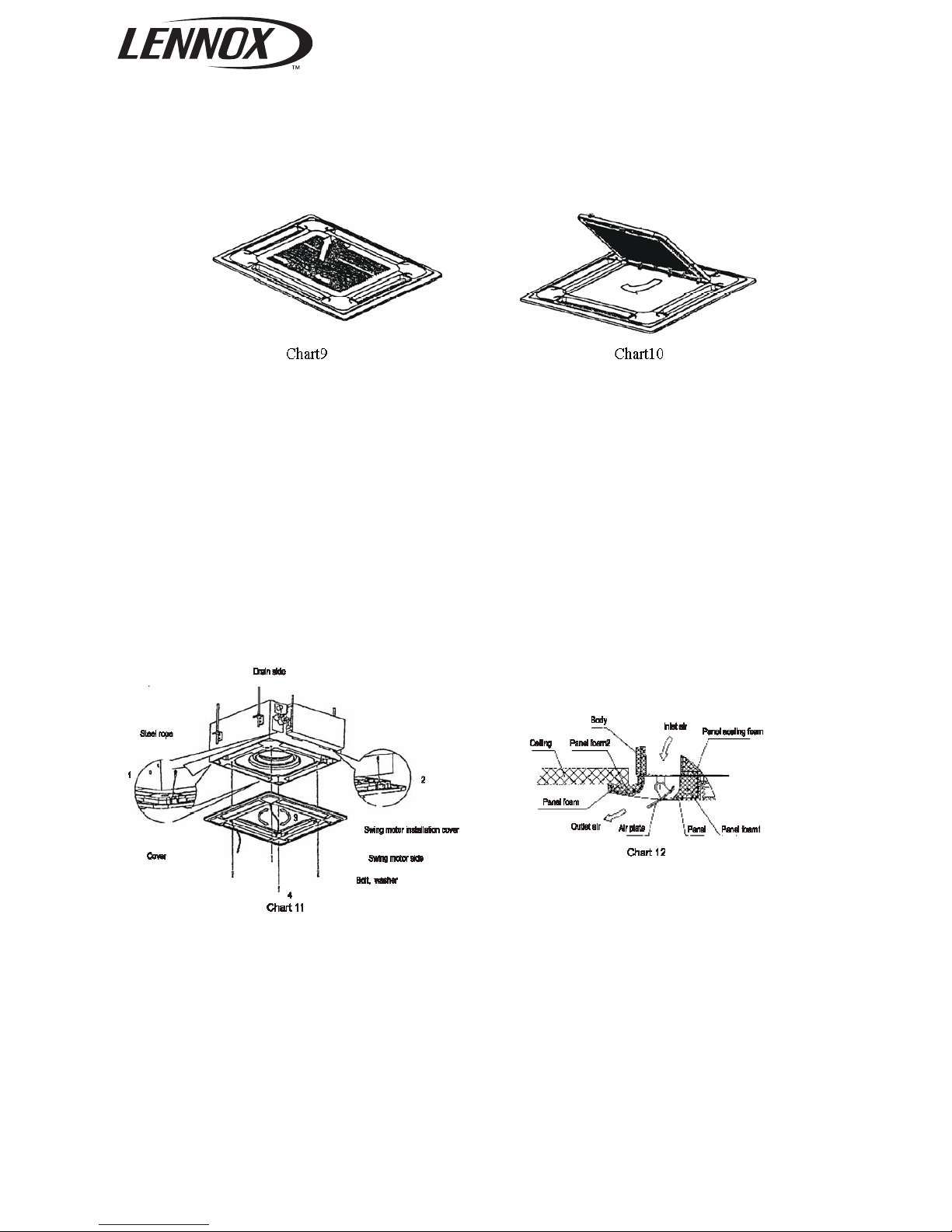
1) Remove the inlet grid.
a. Slide two grid switches toward the middle at the same time, and then pull them up. (Refer to chart 9)
b. Draw the grid up to an angle of about 45, and remove it. (Refer to chart 10)
2) Install the panel
a. Align the swing motor on the panel to the water receiver of the body properly. (Refer to chart 11)
b. Hang the four fixed rope of the main body to the installation cover and the other three covers of the
swing motor: (Refer to chart 11)
CAUTIONS: The installation cover of the swing motor must sink into the corresponding water
receiver.
c. Install the panel on the main body with bolt (M5X16) and washer. (Refer to chart 11)
d. Adjust the four panel hook screws to keep the panel horizontal, and screw them up to the ceiling
evenly.
e. Regulate the panel in the direction of the arrow in Chart 11 (3) slightly to fit the panel's center to the
center of the ceiling's opening. Guarantee that hooks of four corners are fixed well.
f. Keep fastening the screws under the panel hooks, until the thickness of the sponge between the
body and the panel's outlet has been reduced to about 4~6mm. The edge of the panel should
contact with the ceiling well. (Refer to chart 12)
Malfunction described in Chart 13 can be caused by inappropriate tightness the screw.
If the gap between the panel and ceiling still exists after fastening the screws, the height of the
indoor unit should be modified again. You can modify the height of the indoor unit through the
openings on the panel's four corners, if the lift of the indoor unit and the drainpipe is not
influenced (refer to chart 14-right).
3) Hang the air-in grid to the panel, then connect the lead terminator of the swing motor and that of the
control box with corresponding terminators on the body respectively.
 Loading...