

Lennox COMFAIR HH, COMFAIR HH 20, COMFAIR HH 10, COMFAIR HH 30, COMFAIR HH 40 Application Manual
...Page 1
lennoxemeia.com
COMFAIR
HH
APPLICATION
GUIDE
High pressure fan coil unit
840 8000 m
3
/h
COMFAIR HH-AGU-1107-E
Page 2

Page 3
• 1 •Application Guide • COMFAIR HH-AGU-1107-E
HIGH PRESSURE FAN COIL UNITS - HH
General description . . . . . . . . . . . . . . . . . . . . . . . . . . . . . . . . . . . . . . . . . . . . . . .2
General data - Eurovent Conditions . . . . . . . . . . . . . . . . . . . . . . . . . . . . . . . . . . . 4
Technical data . . . . . . . . . . . . . . . . . . . . . . . . . . . . . . . . . . . . . . . . . . . . . . . . . . . 5
Working limits . . . . . . . . . . . . . . . . . . . . . . . . . . . . . . . . . . . . . . . . . . . . . . . . . . . 8
Aeraulic performances . . . . . . . . . . . . . . . . . . . . . . . . . . . . . . . . . . . . . . . . . . . . .9
Sound power spectrum . . . . . . . . . . . . . . . . . . . . . . . . . . . . . . . . . . . . . . . . . . . 13
Air pressure drops for the main accessories . . . . . . . . . . . . . . . . . . . . . . . . . . . 14
Water coil pressure drop diagram . . . . . . . . . . . . . . . . . . . . . . . . . . . . . . . . . . . 15
Dimensional data . . . . . . . . . . . . . . . . . . . . . . . . . . . . . . . . . . . . . . . . . . . . . . . . 16
Accessories . . . . . . . . . . . . . . . . . . . . . . . . . . . . . . . . . . . . . . . . . . . . . . . . . . . . 18
CONTROLLERS
General description . . . . . . . . . . . . . . . . . . . . . . . . . . . . . . . . . . . . . . . . . . . . . . 28
APPLICATION GUIDE
Ref : COMFAIR HH-AGU-1107-E
TABLE OF CONTENTS
COMFAIR HH
High pressure fan coil units
Product designed and manufactured under a quality management system certifi ed ISO 9001.
Our products comply with the European standards.
Our company is a member of the Eurovent Certifi cation Program.
The COMFAIR LENNOX fan coil units are tested and rated in accordance with Eurovent certifi cation program.
All the technical and technological information contained in this manual, including any drawing and technical descriptions provided
by us, remain the property of Lennox and must not be utilised (except in operation of this product), reproduced, issued to or made
available to third parties without the prior written agreement of Lennox.
Page 4
• 2 •
RAM
BAM
PAM
SRE
HH SSP
SFA
Application Guide • COMFAIR HH-AGU-1107-E
GENERAL - HH
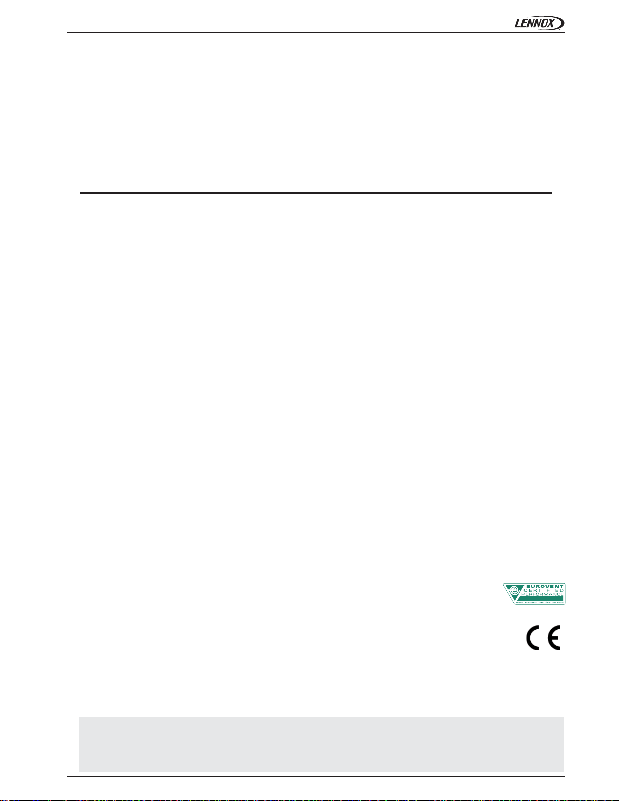
Comfair HH fan coil units are designed to operate against higher external static pressures (from 105 to 260 Pa), and are available in
7 sizes.
All standard units can be supplied with a complete range of factory or site fi tted accessories, allowing a multitude of confi gurations
for all typical applications, for example :
• auxiliary condensate drain pan (UTC)
• air Filter section (SFA)
• auxiliary Coil
• fresh air inlet damper (SSP)
• electric heater (SRE)
• inlet, supply and exhaust air plenums (PAM, RAM et BAM)
FAN SECTION
Composed of one or two double inlet centrifugal fans with aluminium blades, mounted in horizontal position and statically and
dynamically balanced. The electric motor is fi tted with overload protection and has three speeds. It is constructed to comply with all
relevant International standards, with a capacitor permanently in circuit. Motors are connected directly to the fan shafts and are located
on anti-vibration mounts to ensure particularly quiet operation.
CHASSIS
The chassis is manufactured from thick (1mm) galvanised sheet steel.
COILS
Water Heat exchangers are copper tubes with aluminium fi ns, bonded to the tubes by a mechanical
expansion process. Coil connections are of female type antitorsion and headers are fi tted with easily
accessible air-vents.
CONTROL PANEL
Comfair HH fan coil units must be controlled from a separate remote controller. A large selection of controllers
with varying levels of function is available to satisfy most requests.
Options delivered separately : Ambient Thermostats (TA), Minimum water temperature thermostat (TC),
Remote (wall mounted) controllers (CD1, CD2/X1, ... ).
AIR FILTER
Simple to remove, it comprises a metal frame containing a washable acrylic fi lter media (fi ltration effi ciency EU 2).
HIGH PRESSURE FAN COIL UNITS - HH
Page 5

• 3 •Application Guide • COMFAIR HH-AGU-1107-E
MANUAL FRESH AIR INLET DAMPER
Produced form Alu-Zinc sheet metal, it allows the introduction of fresh air up to a maximum of 30% of the total air volume.
ELECTRIC HEATER
Electric heater elements meet all of the relevant International safety standards and are fi tted as standard
with a safety cut-out thermostat and automatic reset. Heater elements are factory fi tted with all electrical
wiring and are connected to the control panel via a contactor.
AUXILIARY COIL
In order to offer the best solutions for 4 pipe applications, a supplementary 1 row coil can be ordered
factory fi tted.
INLET, SUPPLY AND EXHAUST AIR PLENUMS
Plenums are constructed from galvanised sheet steel allow for easy connection to ductwork.
GENERAL - HH
Page 6
• 4 •
10 20 30 40 50
3,11 4,02 5,63 6,11 7,23
3,46 5,02 6,93 7,88 9,44
3,63 5,64 7,36 8,63 11
3,82 5,16 7,21 7,79 8,91
4,2 6,35 8,66 9,81 11,3
4,4 7,05 9,2 10,6 13,1
4,3 6,13 8,66 9,23 11,2
4,75 7,62 10,5 11,8 14,5
4,98 8,51 11,2 12,8 16,9
18,1 19,3 20,8 17,2 16,6
21,9 29,2 30 27,3 26,9
24 35,9 33,8 31,9 35,9
16,7 17 17,7 15,1 15,4
20,2 25,7 25,6 23,9 24,9
22,2 31,7 28,9 27,9 33,2
0,11 0,15 0,3 0,31 0,28
0,12 0,19 0,32 0,34 0,41
0,16 0,24 0,32 0,34 0,58
230/1/50
63 53 61 58 62
67 62 68 65 69
68 66 70 69 74
10 20 30 40 50
2,66 4,02 5,4 5,76 6,89
2,93 5 6,66 7,44 9,02
3,1 5,63 7,07 8,04 10,6
3,13 5,12 6,51 7,03 8,31
3,44 6,3 7,82 8,86 10,6
3,6 7 8,3 9,57 12,3
3,61 5,04 7,5 8,23 9,3
3,98 6,27 8,73 9,93 12
4,18 7 9,17 10,6 14
12 14,4 17,7 13,9 14,2
14,5 21,8 25,2 21,8 23
15,9 26,8 28 25 30,8
20 11,9 25,3 13,3 15
24,3 18,4 33,8 19,3 24,9
26,8 22,9 37 21,7 33,8
0,11 0,14 0,3 0,31 0,28
0,12 0,17 0,32 0,34 0,41
0,16 0,22 0,32 0,34 0,58
230/1/50
63 53 61 59 61
67 62 68 66 68
69 66 70 70 73
Application Guide • COMFAIR HH-AGU-1107-E
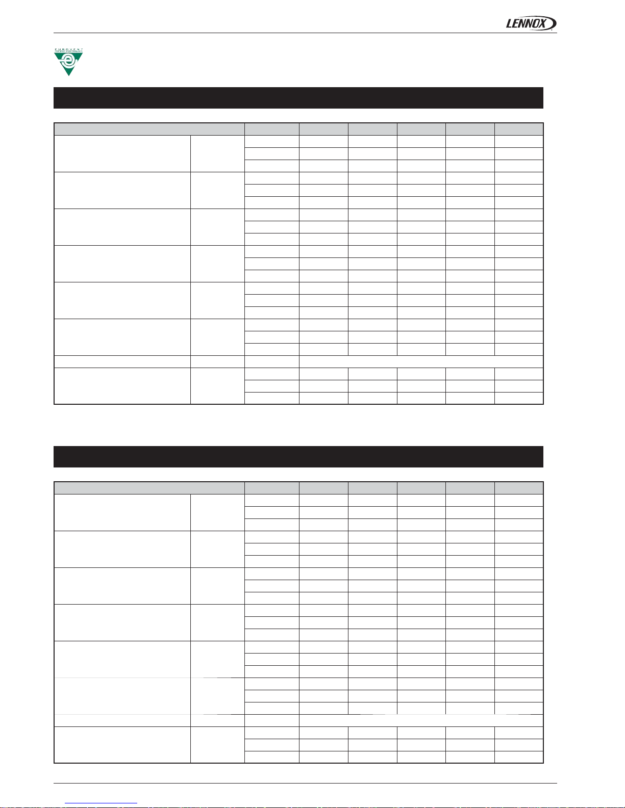
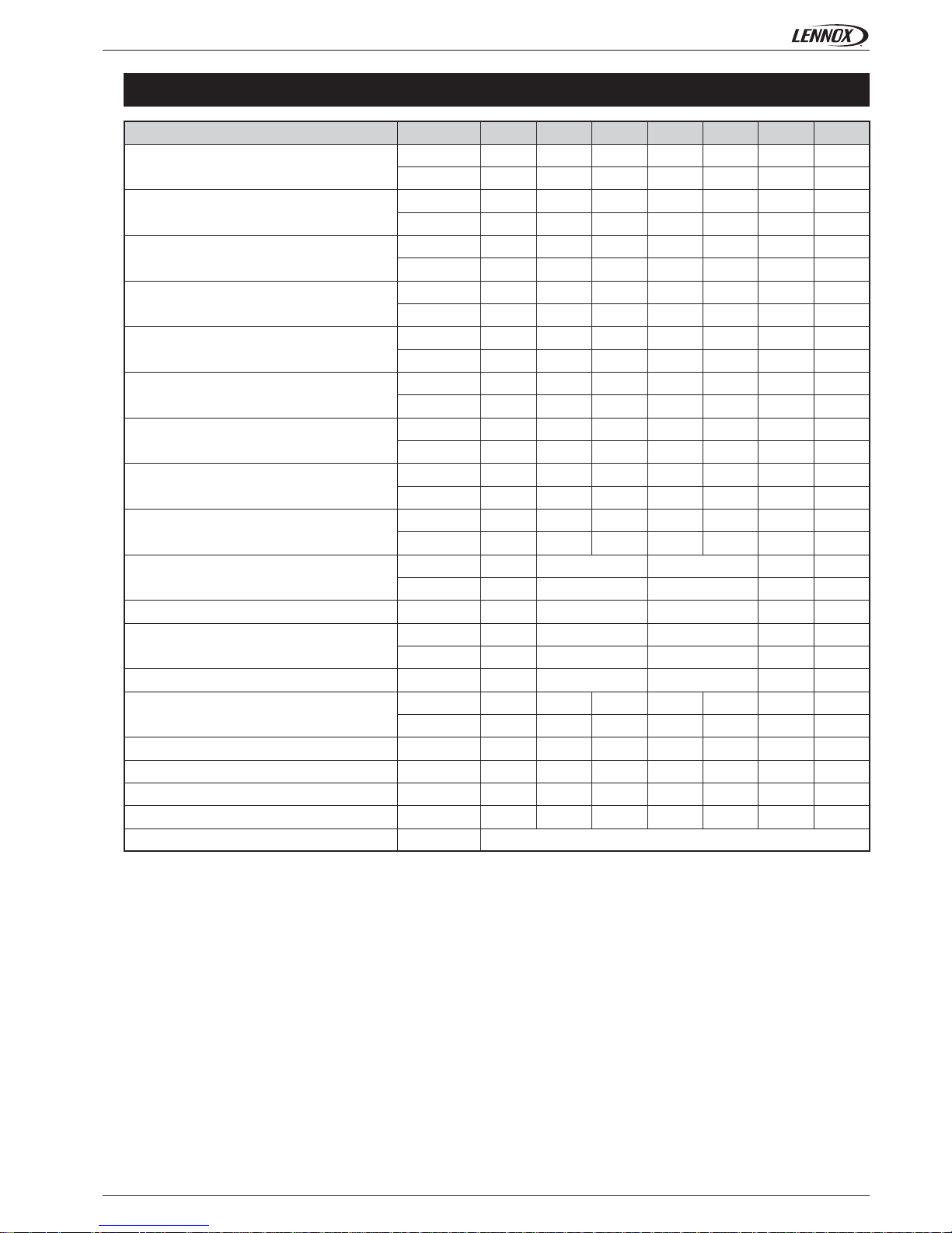
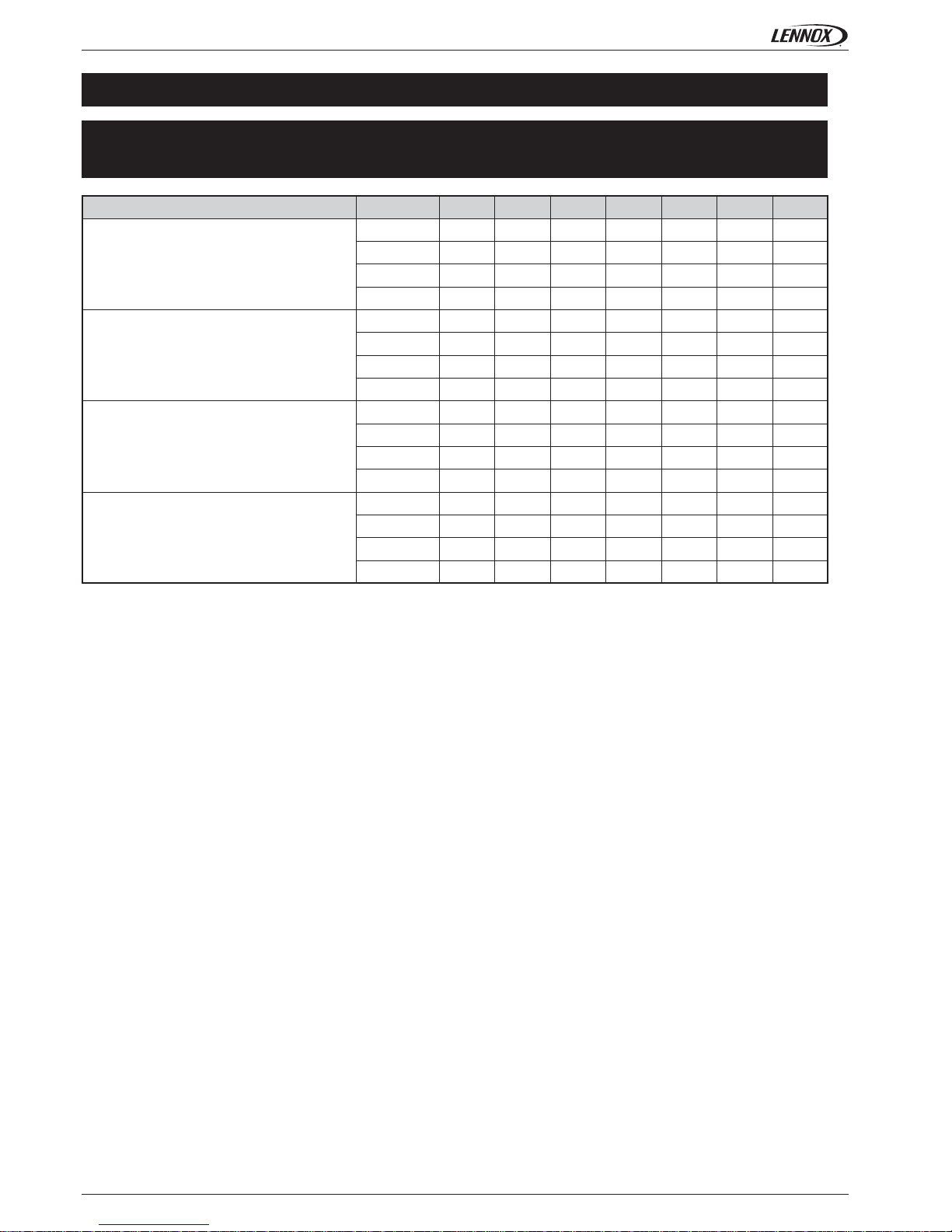
GENERAL DATA - EUROVENT CONDITIONS - HH
All data are at Eurovent conditions.
http://www.eurovent-certifi cation.com/
PROGRAM: FC-2-H
PROGRAM: FC-4-H
COMFAIR HH
Sensible cooling capacity kW
Min
Med
Max
Total cooling capacity kW
Min
Med
Max
Heating capacity kW
Min
Med
Max
Water pressure drops in cooling kPa
Min
Med
Max
Water pressure drops in heating kPa
Min
Med
Max
Fan electrical power kW
Min
Med
Max
Voltage V/Ph/Hz -
Sound power level dB(A)
Min
Med
Max
Page 7
• 5 •
10 20 30 40 50 60 70
3640 7050 9200 10600 13100 27800 50600
3130 6063 7912 9116 11266 23908 43516
2870 5640 7360 8630 11000 21100 39500
2,468 4,85 6,33 7,422 9,46 18,146 33,97
4972 8512 11210 12800 16818 32430 60111
4276 7320 9641 11008 14464 27890 51696
626 1213 1582 1823 2253 4782 8703
0,174 0,337 0,441 0,506 0,626 1,328 2,418
24 35,9 33,8 31,9 35,9 34 40
2,4 3,7 3,4 3,3 3,7 3,5 4,1
22,2 31,7 28,9 27,9 33,2 24 30
2,3 3,2 2,9 2,8 3,4 2,4 3,1
8400 14300 18850 21520 28490 54240 100810
7224 12298 16211 18507 24502 46647 86698
722 1230 1621 1850 2450 4664 8670
0,201 0,342 0,45 0,514 0,681 1,296 2,408
18,3 29,6 27,5 26,1 35,6 20,7 27
1,9 3 2,8 2,7 3,6 2,1 2,8
3000 6000 9000 12000 18000
2586 5172 7759 10345 15517
4,56 9,12 13,67 18,23 27,35
4500 9000 12000 18000 24000
3879 7759 10345 15517 20690
6,84 13,67 18,23 27,35 36,46
837 1423 1951 2131 3002 4678 9250
0,233 0,395 0,542 0,592 0,834 1,299 2,569
1360 1360 1200 1207 1382 806 822
68 66 70 69 75 78 81
160 240 320 340 580 1320 2600
0,72 0,97 1,43 1,51 2,58 5,86 11,54
230/1/50
Application Guide • COMFAIR HH-AGU-1107-E
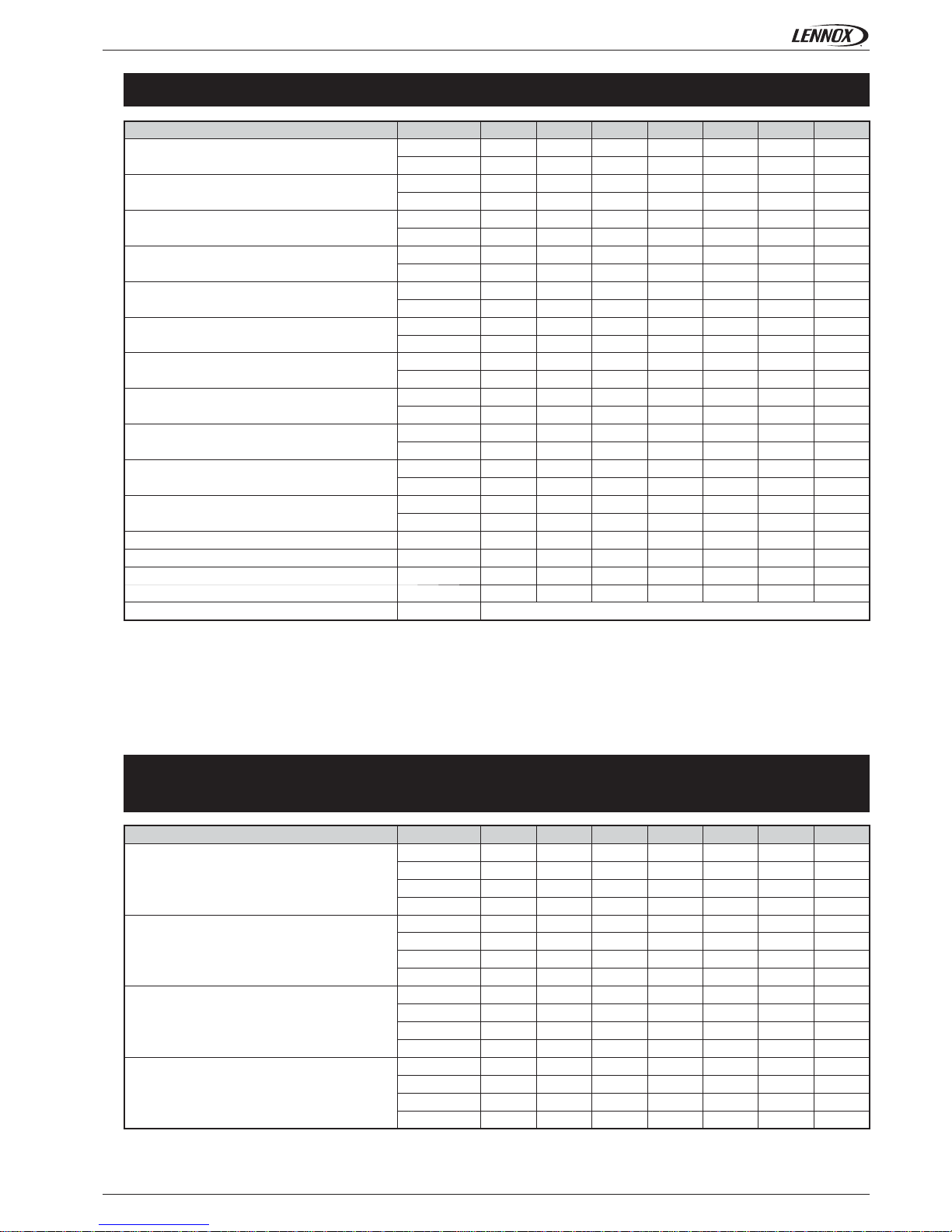
TECHNICAL DATA - HH
2 PIPES SYSTEM
COMFAIR HH
Total cooling capacity
(1)
W
Frig/h
Sensible cooling capacity
(1)
W
Frig/h
Heating capacity
(3)
W
kcal/h
Water fl ow
(1) (3)
l/h
l/s
Water pressure drops in cooling
(1)
kPa
mWG.
Water pressure drops in heating
(3)
kPa
mWG.
Heating capacity
(2)
W
kcal/h
Water fl ow
(2)
l/h
l/s
Water pressure drops in heating
(2)
kPa
mWG.
Electrical heater heating capacity
(4)
W
kcal/h
Electrical heater power input
(4)
A
Electrica heater heating capacity
(5)
W
kcal/h
Electrical heater input current
(5)
A
Air fl ow
(6)
m3/h
m
3
/s
Fan speed
(6)
rpm
Sound power level
(7)
dB(A)
Motor electrical power
(8)
W
Motor electrical input
(8)
A
Electrical supply V/Ph/Hz
Above mentionned technical data are calculated ar the following operating conditions:
- Maximum fan speed
- Standard unit without ducts (fancoil operating without external back pressure)
(1) Cooling: entering water temperature 7°C, leaving water temperature 12°C, entering air temperature 27°C W.B.; 19°C D.B.
(2) Heating: entering water temperature 50°C, same water fl ow as in cooling, entering air temperature 20°C
(3) Heating: entering water temperature 70°C, leaving water temperature 60°C, entering air temperature 20°C
(4) Electric heaters section SRE - B: electric heaters capacities, lower speed cabling (SRE - B supplied as accessory only)
(5) Electric heaters section SRE - A: electric heaters capacities, high speed cabling (SRE - A supplied as accessory only)
(6) Air fl ow and fan speed: fancoil performances with cleaned fi lter
(7) Sound power level: sound power measured following ISO 23741
(8) Electrical data referred to the maximum available speed
Page 8
• 6 •
10 20 30 40 50 60 70
0,98 0,96
-----
0,98 0,95
-----
0,98 0,96
-----
0,97 0,94
-----
Application Guide • COMFAIR HH-AGU-1107-E
TECHNICAL DATA - HH
CORRECTION COEFFICIENT FOR DIFFERENT AVAILABLE SPEEDS
2 PIPES SYSTEM
COMFAIR HH 10 20 30 40 50 60 70
Total cooling capacity
1 0,84 min 0,74 min 0,79 min 0,74 min 0,68 min 0,77 min 0,78 min
2 0,95 med 0,90 med 0,94 med 0,93 med 0,87 med 0,89 med 0,90 med
3 1,00 max 1,00 max 1,00 max 1,00 max 1,00 max
4 1,00 max 1,00 max
Sensible cooling capacity
1 0,86 min 0,71 min 0,77 min 0,71 min 0,65 min 0,75 min 0,76 min
2 0,95 med 0,89 med 0,94 med 0,91 med 0,85 med 0,88 med 0,89 med
3 1,00 max 1,00 max 1,00 max 1,00 max 1,00 max
4 1,00 max 1,00 max
Heating capacity
1 0,86 min 0,72 min 0,77 min 0,72 min 0,67 min 0,75 min 0,77 min
2 0,95 med 0,90 med 0,94 med 0,92 med 0,86 med 0,88 med 0,89 med
3 1,00 max 1,00 max 1,00 max 1,00 max 1,00 max
4 1,00 max 1,00 max
Air fl ow
1 0,81 min 0,63 min 0,69 min 0,63 min 0,56 min 0,69 min 0,70 min
2 0,93 med 0,85 med 0,91 med 0,89 med 0,80 med 0,84 med 0,85 med
3 1,00 max 1,00 max 1,00 max 1,00 max 1,00 max
4 1,00 max 1,00 max
Data indicated as min., med., max. concern the 3 standard speeds set at the factory. Upon customer request other 3 speeds among the 6 speeds available can be
connected.
NOTE: The symbol (-) means that for HH30 to HH70, only 3 fan speeds are available. For HH10 and HH20, upon customer request other 3 speeds among the 4 available
speeds can be connected.
Page 9
• 7 •
10 20 30 40 50 60 70
3600 7000 8300 9570 12300 24950 45550
3096 6020 7138 8230 10578 21457 39173
3100 5630 7070 8040 10600 20150 37750
2666 4842 6080 6914 9116 17329 32465
4180 7000 9170 10600 14000 38800 70150
3595 6020 7886 9116 12040 33368 60330
619 1205 1428 1646 2116 4291 7835
0,172 0,335 0,397 0,457 0,588 1,192 2,176
360 602 789 912 1204 3337 6033
0,1 0,167 0,219 0,253 0,334 0,927 1,676
15,9 26,8 28 25 30,8 27 32
1,6 2,7 2,9 2,5 3,1 2,8 3,3
26,8 22,9 37 21,7 33,8 33 36
2,7 2,3 3,8 2,2 3,4 3,4 3,7
2557 4275 5593 6441 8547 23730 42898
2204 3686 4822 5553 7368 20457 36981
446 746 976 1124 1492 4141 7486
0,124 0,207 0,271 0,312 0,414 1,15 2,079
46 39 62 36 58 56 62
4,7 4 6,3 3,7 5,9 5,8 6,3
795 1352 1853 2024 2852 4444 8788
0,221 0,376 0,515 0,562 0,792 1,234 2,441
1365 1365 1205 1214 1387 810 832
69 66 70 70 73 78 81
162 218 322 340 582 1320 2600
0,72 0,97 1,43 1,51 2,58 5,86 11,54
230/1/50
10 20 30 40 50 60 70
0,98 0,96
-----
0,98 0,96
-----
0,98 0,97
-----
0,97 0,94
-----
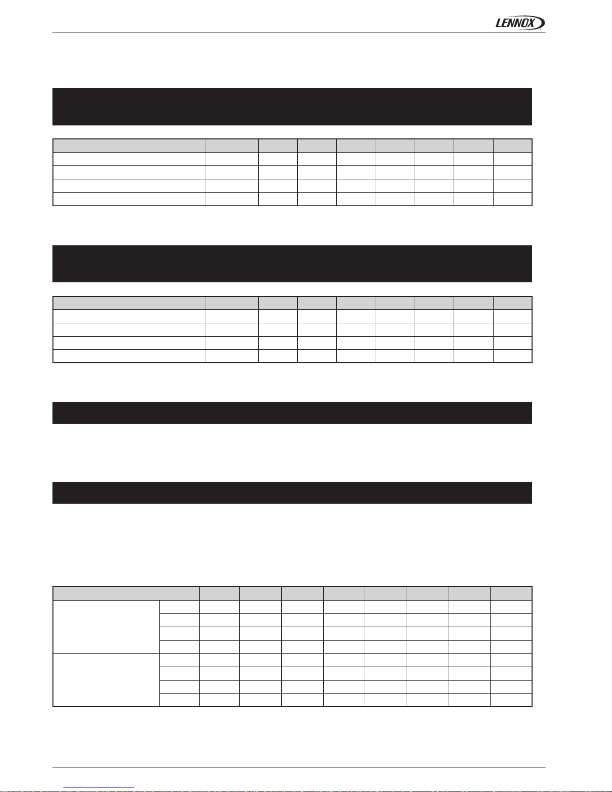
Application Guide • COMFAIR HH-AGU-1107-E
TECHNICAL DATA - HH
Above mentionned technical data are calculated ar the following operating conditions:
- Maximum fan speed
- Standard unit without ducts (fancoil operating without external back pressure)
(1) Cooling: entering water temperature 7°C, leaving water temperature 12°C, entering air temperature 27°C W.B.; 19°C D.B.
(2) Heating: entering water temperature 70°C, leaving water temperature 60°C, entering air temperature 20°C
(3) Heating: entering water temperature 50°C, same water fl ow as in cooling, entering air temperature 20°C
(4) Air fl ow and fan speed: fancoil performances with cleaned fi lter
(5) Sound power level: sound power measured following ISO 23741
(6) Electrical data referred to the maximum available speed
Data indicated as min., med., max. concern the 3 standard speeds set at the factory. Upon customer request other 3 speeds among the 6 speeds available can be
connected.
NOTE: The symbol (-) means that for HH30 to HH70, only 3 fan speeds are available. For HH10 and HH20, upon customer request other 3 speeds among the 4 available
speeds can be connected.
4 PIPES SYSTEM
CORRECTION COEFFICIENT FOR DIFFERENT AVAILABLE SPEEDS
COMFAIR HH
Total cooling capacity
(1)
W
Frig/h
Sensible cooling capacity
(1)
W
Frig/h
Heating capacity
(2)
W
kcal/h
Water fl ow in cooling
(1)
l/h
l/s
Water fl ow in heating
(2)
l/h
l/s
Water pressure drops in cooling
(1)
kPa
mWG.
Water pressure drops in heating
(2)
kPa
mWG.
Heating capacity
(3)
W
kcal/h
Water fl ow
(3)
l/h
l/s
Water pressure drops in heating
(3)
kPa
mWG.
Air fl ow
(4)
m3/h
m3/s
Fan speed
(4)
rpm
Sound power level
(5)
dB(A)
Motor electrical power
(6)
W
Motor electrical input
(6)
A
Electrical supply V/Ph/Hz
COMFAIR HH
Total cooling capacity
1 0,87 min 0,73 min 0,78 min 0,73 min 0,68 min 0,76 min 0,78 min
2 0,96 med 0,90 med 0,94 med 0,93 med 0,86 med 0,89 med 0,90 med
3 1,00 max 1,00 max 1,00 max 1,00 max 1,00 max
4 1,00 max 1,00 max
Sensible cooling capacity
1 0,86 min 0,71 min 0,76 min 0,72 min 0,65 min 0,74 min 0,76 min
2 0,94 med 0,89 med 0,94 med 0,93 med 0,85 med 0,87 med 0,89 med
3 1,00 max 1,00 max 1,00 max 1,00 max 1,00 max
4 1,00 max 1,00 max
Heating capacity
1 0,89 min 0,77 min 0,82 min 0,78 min 0,73 min 0,78 min 0,80 min
2 0,96 med 0,92 med 0,95 med 0,94 med 0,89 med 0,90 med 0,91 med
3 1,00 max 1,00 max 1,00 max 1,00 max 1,00 max
4 1,00 max 1,00 max
Air fl ow
1 0,81 min 0,63 min 0,69 min 0,63 min 0,56 min 0,69 min 0,70 min
2 0,93 med 0,85 med 0,91 med 0,89 med 0,80 med 0,84 med 0,85 med
3 1,00 max 1,00 max 1,00 max 1,00 max 1,00 max
4 1,00 max 1,00 max
Page 10
• 8 •
10 20 30 40 50 60 70
175 225 275 325 375 825 1400
1,3 1,1 1 1 1 1 1
1300 1850 2275 2700 3150 6900 11575
70,8 71,9 70 69,9 70,1 70,4 70,3
10 20 30 40 50 60 70
75 125 150 200 225 600 1025
1,2 1 1,3 1 1,2 1,1 1
575 1050 1100 1650 1725 4900 8450
68,5 69,7 70 69,2 69,6 70,7 70,2
10 20 30 40 50 60 70
1
2
3 100 100
4 -----
1
2
39085
4 -----
Application Guide • COMFAIR HH-AGU-1107-E
Data indicated as min., med., max. concern the 3 standard speeds set at the factory. Upon customer request other 3 speeds among the 6 speeds available can be
connected.
NOTE: The symbol (-) means that for HH30 to HH70, only 3 fan speeds are available. For HH10 and HH20, upon customer request other 3 speeds among the 4 available
speeds can be connected.
WORKING LIMITS - HH
Maximum entering water temperature: 70°C Maximum entering air temperature: 40°C
Minimum entering water temperature: +4°C Minimum entering air temperature: +4°C
Maximum working pressure: 8 Bar
WATER FLOW AND PRESSURE DROP LIMITS, 3R COIL (HH10 TO HH50)
AND 4R COIL (HH60 AND HH70)
WATER FLOW AND PRESSURE DROP LIMITS, 1 ROW COIL (HH10 TO
HH50) AND 2R COIL (HH60 AND HH70)
Data given for medium water temperature at 9,5°C
3 WAYS VALVE
Using of 2 or 3 ways valves is compulsory when the unit is used for cooling to avoid condensate in the external structure (bearing
structure and cabinet). As alternative install a regulating system to stop coil water entering when the fan is off.
When the units is connected with ducts fan air fl ow is reduced due to the ducting pressure drops.
With very high pressure drops fancoil air fl ow becomes too low and electric motor which is connected to the fan can be damaged. For
this reason we recommand static pressures lower than the maximum limit static pressures indicated in the schedule.
NOTE: When the fancoil is operating with the maximum operating indicated static pressure value, air fl ow is half in comparison with
the unit without ducts at the same working speed. Defi nitively the static presure limit corresponds to the back pressure ables to half
fancoil air fl ow (as a consequence the fancoil unit performances like heating & cooling capacity, will be reduced of about 50%).
MAXIMUM FAN STATIC PRESSURE
Data given for medium water temperature at 65°C
COMFAIR HH
Minimal water fl ow l/h
Minimal water pressure drop kPa
Maximal water fl ow l/h
maximal water pressure drop kPa
COMFAIR HH
Minimal water fl ow l/h
Minimal water pressure drop kPa
Maximal water fl ow l/h
maximal water pressure drop kPa
COMFAIR HH
2 pipes system
Pa 90 min 80 min 115 min 105 min 135 min 220 min 220 min
Pa 95 med 95 med 130 med 130 med 180 med 240 med 240 med
Pa 135 max 135 max 205 max 260 max 260 max
Pa 105 max 105 max
4 pipes system
Pa 75 min 70 min 95 min 90 min 110 min 180 min 180 min
Pa 85 med 80 med 115 med 115 med 155 med 210 med 210 med
Pa 120 max 120 max 180 max 220 max 220 max
Pa 95 max 90 max
Page 11

• 9 •
MIN
MED
MAX
MIN
MED
MAX
MIN
MED
MAX
Application Guide • COMFAIR HH-AGU-1107-E
AERAULIC PERFORMANCES - HH
HH10 - 2 PIPES SYSTEM (3 ROW COIL DATA)
Air fl ow (m3/h)
Available static pressure (Pa)
Working limit
Air fl ow (m
3
/h)
Available static pressure (Pa)
Working limit
Air fl ow (m
3
/h)
Available static pressure (Pa)
Working limit
Data indicated as min., med., max. concern the 3 standard speeds set at the factory. Upon customer request other 3 speeds among the 6 speeds available can be
connected.
MAX
MED
MIN
MAX
MED
MIN
MAX
MED
MIN
HH20 - 2 PIPES SYSTEM (3 ROW COIL DATA)
HH30 - 2 PIPES SYSTEM (3 ROW COIL DATA)
Page 12

• 10 •
MIN
MED
MAX
MIN
MED
MAX
MIN
MED
MAX
MIN
MED
MAX
Application Guide • COMFAIR HH-AGU-1107-E
AERAULIC PERFORMANCES - HH
HH40 - 2 PIPES SYSTEM (3 ROW COIL DATA)
Air fl ow (m3/h)
Available static pressure (Pa)
Working limit
Air fl ow (m
3
/h)
Available static pressure (Pa)
Working limit
Data indicated as min., med., max. concern the 3 standard speeds set at the factory. Upon customer request other 3 speeds among the 6 speeds available can be
connected.
Air fl ow (m3/h)
Available static pressure (Pa)
Working limit
MAX
MED
MIN
MAX
MED
MIN
MAX
MED
MIN
HH70 - 2 PIPES SYSTEM (3 ROW COIL DATA)
Air fl ow (m3/h)
Available static pressure (Pa)
Working limit
MAX
MED
MIN
HH50 - 2 PIPES SYSTEM (3 ROW COIL DATA)
HH60 - 2 PIPES SYSTEM (3 ROW COIL DATA)
Page 13

• 11 •
MIN
MED
MAX
MIN
MED
MAX
MIN
MED
MAX
Application Guide • COMFAIR HH-AGU-1107-E
AERAULIC PERFORMANCES - HH
HH10 - 4 PIPES SYSTEM (3 ROW + 1 ROW COIL DATA)
Air fl ow (m3/h)
Available static pressure (Pa)
Working limit
Air fl ow (m3/h)
Available static pressure (Pa)
Working limit
Air fl ow (m
3
/h)
Available static pressure (Pa)
Working limit
Data indicated as min., med., max. concern the 3 standard speeds set at the factory. Upon customer request other 3 speeds among the 6 speeds available can be
connected.
MAX
MED
MIN
MAX
MED
MIN
MAX
MED
MIN
HH20 - 4 PIPES SYSTEM (3 ROW + 1 ROW COIL DATA)
HH30 - 4 PIPES SYSTEM (3 ROW + 1 ROW COIL DATA)
Page 14

• 12 •
MIN
MED
MAX
MIN
MED
MAX
MIN
MED
MAX
MIN
MED
MAX
Application Guide • COMFAIR HH-AGU-1107-E
HH50 - 4 PIPES SYSTEM (3 ROW + 1 ROW COIL DATA)
HH60 - 4 PIPES SYSTEM (3 ROW + 1 ROW COIL DATA)
AERAULIC PERFORMANCES - HH
HH40 - 4 PIPES SYSTEM (3 ROW + 1 ROW COIL DATA)
Air fl ow (m3/h)
Available static pressure (Pa)
Working limit
Air fl ow (m
3
/h)
Available static pressure (Pa)
Working limit
Data indicated as min., med., max. concern the 3 standard speeds set at the factory. Upon customer request other 3 speeds among the 6 speeds available can be
connected.
Air fl ow (m3/h)
Available static pressure (Pa)
Working limit
MAX
MED
MIN
HH70 - 4 PIPES SYSTEM (3 ROW + 1 ROW COIL DATA)
Air fl ow (m3/h)
Available static pressure (Pa)
Working limit
Page 15

• 13 •
125 250 500 1000 2000 4000 8000
1 68,1 60,6 59,3 57,9 54,9 52,3 45,9 63
2 71,4 64,5 62,8 62 59 57 51,5 67
3 71,4 65,4 63,3 62,5 59,6 57,6 52,6 67,5
4 71,9 65,7 63,7 62,9 60,1 58,2 53,4 68
1 57,2 51,4 50,9 47,6 44,8 39,5 32 53
2 65,2 60 58,7 56,9 54,1 51,3 45,3 62
3 66,9 61,7 60,1 58,9 56,1 53,8 48,6 64
4 68,4 63,9 61,8 60,6 58,2 56,2 51,4 66
1 61,9 57,6 58,7 55,9 53 49,6 42,7 61
2 67,6 64,2 64,8 64 60,4 52 54 68
3 68,3 65,6 63,8 66,2 62,1 60,9 56,6 70
1 67,5 53,5 54,2 51,9 49,6 46 38,6 58
2 68,3 59,7 61 59,8 57,2 56,2 51,4 65
3 69,2 63,3 64,1 64,3 61 60,5 56,7 69
1 63,7 57,8 58,4 58 54,8 48,2 39,1 62
2 70,4 64,7 63,6 64,2 62,6 59,3 52,2 69
3 75,6 71,2 68,8 69,6 68,7 66,5 61,1 75
1 71,3 66,3 68,8 63,4 58,1 54,1 41,6 69
2 73,8 69 72,7 67,7 62,5 59 48 73
3 74 73,6 77,3 73,1 68,1 64,8 54,7 78
1 67,3 67,8 70,6 65,8 61 56,8 44,7 71
2 75,9 72 75,1 71,2 66,3 62,9 51,9 76
3 73,7 76,9 79,3 76,7 71,9 68,7 58,9 81
125 250 500 1000 2000 4000 8000
1 68,1 60,6 59,3 57,9 54,9 52,3 45,9 63
2 71,4 64,5 62,8 62 59 57 51,5 67
3 71,9 65,9 63,8 63 60,1 58,1 53,1 68
4 72,9 66,7 64,7 63,9 61,1 59,2 53,4 69
1 57,2 51,4 50,9 47,6 44,8 39,5 32 53
2 65,2 60 58,7 56,9 54,1 51,3 45,3 62
3 66,9 61,7 60,1 58,9 56,1 53,8 48,6 64
4 68,4 63,9 61,8 60,9 58,2 56,2 51,4 66
1 61,9 57,6 58,7 55,9 53 49,6 42,7 61
2 67,6 64,2 64,8 64 60,4 52 54 68
3 68,3 65,6 63,8 66,2 62,1 60,9 56,6 70
1 68,5 54,5 55,2 52,9 50,6 47 39,6 59
2 69,3 60,7 62 60,8 58,2 57,2 52,4 66
3 70,2 64,3 65,1 65,3 62 61,5 57,7 70
1 62,7 56,8 57,4 57 53,8 47,2 38,1 61
2 69,4 63,7 62,6 63,2 61,6 58,3 51,2 68
3 73,6 69,2 66,8 67,6 66,7 64,5 59,1 73
1 71,3 66,3 68,8 63,4 58,1 54,1 41,6 69
2 73,8 69 72,7 67,7 62,5 59 48 73
3 74 73,6 77,3 73,1 68,1 64,8 54,7 78
1 67,3 67,8 70,6 65,8 61 56,8 44,7 71
2 75,9 72 75,1 71,2 66,3 62,9 51,9 76
3 73,7 76,9 79,3 76,7 71,9 68,7 58,9 81
Application Guide • COMFAIR HH-AGU-1107-E
SOUND POWER SPECTRUM - HH
2 PIPES SYSTEM
COMFAIR Speeds
Std electric
wiring (*)
Frequence spectrum - Ref. octave band (Hz)
Total sound
power (dB(A))
HH10
Min
Med
Max
HH20
Min
Med
Max
HH30
Min
Med
Max
HH40
Min
Med
Max
HH50
Min
Med
Max
HH60
Min
Med
Max
HH70
Min
Med
Max
COMFAIR Speeds
Std electric
wiring (*)
Frequence spectrum - Ref. octave band (Hz)
Total sound
power (dB(A))
HH10
Min
Med
Max
HH20
Min
Med
Max
HH30
Min
Med
Max
HH40
Min
Med
Max
HH50
Min
Med
Max
HH60
Min
Med
Max
HH70
Min
Med
Max
4 PIPES SYSTEM
Data indicated as min., med., max. concern the 3 standard speeds set at the factory. Upon customer request other 3 speeds among the 6 speeds available can be connected.
Page 16

• 14 •
8,7 7,5 1,2 2,8 5,3 50,6 55,1 110
7,9 6,9 1,1 2,5 4,8 46,2 50,4 101
6,1 5,3 0,8 1,9 3,7 35,4 38,5 77,1
4,5 3,9 0,6 1,4 2,7 26 28,3 56,6
3,1 2,7 0,4 1 1,9 18 19,7 39,3
2 1,7 0,3 0,6 1,2 11,5 12,6 25,2
1,3 1,2 - 0,4 0,8 7,9 8,6 17,1
9,3 8,1 1,2 2,9 8,4 52,1 56,7 113
9 7,8 1,2 2,8 8,1 50,4 54,9 110
6,6 5,7 0,9 2,1 6 37 40,3 80,7
4,6 4 0,6 1,4 4,1 25,7 28 56
2,9 2,5 0,4 0,9 2,7 16,5 17,9 35,9
1,6 1,4 - 0,5 1,5 9,3 10,1 20,2
0,7 0,6 - - 0,7 4,1 4,5 9
14,1 12,2 1,6 4,4 15,8 59,5 64,9 130
12 10,4 1,4 3,8 13,5 50,7 55,2 110
9,5 8,2 1,1 3 10,6 40 43,6 87,3
7,2 6,3 0,8 2,3 8,2 30,6 33,4 66,8
5,3 4,6 0,6 1,7 6 22,5 24,5 49,1
3,7 3,2 0,4 1,2 4,2 15,6 17 34,1
2,4 2,1 0,3 0,7 2,7 10 10,9 21,8
1,6 1,4 - 0,5 1,8 6,6 7,2 14,4
10,9 9,5 1,3 3,4 10,7 45,6 49,7 99,4
9,6 8,3 1,2 3 9,4 40,2 43,8 87,6
7,8 6,8 0,9 2,5 7,6 32,5 35,5 70,9
6,1 5,3 0,7 1,9 6 25,7 28 56
4,7 4,1 0,6 1,5 4,6 19,7 21,5 42,9
3,5 3 0,4 1,1 3,4 14,5 15,8 31,5
2,4 2,1 0,3 0,8 2,4 10 10,9 21,9
1,5 1,3 - 0,5 1,5 6,4 7 14
1 0,9 - 0,3 1 4,2 4,6 9,2
15,4 13,4 1,6 4,4 21,8 57 62,1 124
11,6 10,1 1,2 3,3 16,4 42,7 46,6 93,1
8,3 7,2 0,9 2,4 11,7 30,6 33,3 66,7
5,5 4,8 0,6 1,6 7,8 20,5 22,3 44,6
3,4 2,9 0,3 1 4,7 12,4 13,5 27
1,7 1,5 - 0,5 2,4 6,3 6,9 13,8
1,1 1 - 0,3 1,5 4 4,4 8,8
8,5 7,4 0,9 2,5 13,7 27,6 30,1 60,1
7,9 6,8 0,9 2,3 12,7 25,5 27,8 55,6
6,2 5,4 0,7 1,8 10 20,2 22 43,9
4,8 4,1 0,5 1,4 7,7 15,4 16,8 33,6
3,5 3 0,4 1 5,6 11,3 12,4 24,7
2,4 2,1 0,3 0,7 3,9 7,9 8,6 17,2
1,6 1,4 - 0,5 2,5 5 5,5 11
1 0,9 - 0,3 1,6 3,2 3,5 7
13,7 11,9 1,4 4 12,4 43,8 47,8 95,5
12,9 11,2 1,3 3,8 11,7 41,5 45,2 90,4
10,7 9,3 1,1 3,1 9,7 34,4 37,5 75,1
8,7 7,6 0,9 2,5 7,9 28 30,6 61,1
6,9 6 0,7 2 6,3 22,3 24,3 48,6
5,4 4,7 0,6 1,6 4,9 17,2 18,8 37,5
4 3,5 0,4 1,2 3,6 12,8 14 27,9
2,8 2,4 0,3 0,8 2,6 9 9,8 19,7
1,8 1,6 - 0,5 1,7 5,9 6,5 12,9
1,6 1,4 - 0,5 1,5 5,2 5,7 11,4
Application Guide • COMFAIR HH-AGU-1107-E
AIR PRESSURE DROPS FOR THE MAIN ACCESSORIES - HH
Air fl ow dB(A)
Description of the accessories
Fresh air lower
section (SSP)
With completely
open fresh air
Lower position
Fresh air lower
section (SSP)
With completely
closed fresh air
Lower position
Straight intake/
Supply plenum
(PAM)
90° intake/supply
plenum (RAM)
Intake/Supply
section with
spigot section
(BAM)
Heating section
with electricl
heater (SRE)
Standard air
fi lter in medium
stemming
condition
Standard air fi lter
in limit stemming
condition
CLEANING IS
NECESSARY
COMFAIR HH10
837
800
700
600
500
400
330
COMFAIR HH20
1423
1400
1200
1000
800
600
400
COMFAIR HH30
1951
1800
1600
1400
1200
1000
800
650
COMFAIR HH40
2131
2000
1800
1600
1400
1200
1000
800
650
COMFAIR HH50
3002
2600
2200
1800
1400
1000
800
COMFAIR HH60
4678
4500
4000
3500
3000
2500
2000
1600
COMFAIR HH70
9250
9000
8200
7400
6600
5800
5000
4200
3400
3200
Page 17

• 15 •Application Guide • COMFAIR HH-AGU-1107-E
STANDARD COIL (Ref. water medium temperature 9,5°C)
Water fl ow (l/h)
Water pressure drops (kPa)
Water fl ow (l/h)
Water pressure drops (kPa)
AUXILIARY COIL (Ref. water medium temperature 65°C)
WATER COIL PRESSURE DROP DIAGRAM - HH
Page 18

• 16 •
10 20 30 40 50 60 70
1-1 2-1 2-1 2-1 2-1 1-1 2-2
34
523 873 973 1213 1900
11 12 14 26
2,1
345681626
25x22
66 88
0,144 0,240 0,292 0,364 0,425 0,788 1,235
8,128 13,567 16,495 20,564 23,991 59,407 93,053
1,36 2,18 2,63 3,25 3,79 9,38 14,44
1/2” 3/4” 1” 1”1/4 1”1/2
738 1088 1188 1428 1428 1481 2168
548 898 998 1238 1238 1239 1926
650 1000 1100 1340 1340 1341 2028
300 325 375 675
232 275 575
41 65 75
533 852
96 107 133 235
100 200
35 43
65
28 36 41 46 57 117 192
Application Guide • COMFAIR HH-AGU-1107-E
DIMENSIONAL DATA - HH
GENERAL DIMENSIONS - 2 PIPES SYSTEM
Models HH10 to HH50
Models HH60 and HH70
COMFAIR HH
Fans motor number nr
Coil used for both cooling
and heating
Rows number nr
Finned pack length mm
Number of pipes per row nr
Fin spacing mm
Number of feeding circuits nr
Shape mmxmm
Finned pack depth mm
Frontal surface m²
Total surface of fi ns m²
Water content liter
Hydraulic connections (Ø male gas) Ø
Unit general features
Amm
Bmm
Cmm
Dmm
Emm
Fmm
Gmm
Hmm
Imm
Nmm
Omm
Net weight kg
Page 19

• 17 •
10 20 30 40 50 60 70
1-1 2-1 2-1 2-1 2-1 1-1 2-2
34
523 873 973 1213 1213 1213 1900
11 12 14 26
2
345681626
25x22
66 88
0,144 0,240 0,292 0,364 0,425 0,788 1,235
8,128 13,567 16,495 20,564 23,991 59,407 93,053
1,36 2,18 2,63 3,25 3,79 9,38 14,44
1/2” 3/4” 1” 1”1/4 1”1/2
12
523 873 973 1213 1900
11 12 14 26
2,1
12 31016
25x25
25
0,144 0,240 0,292 0,364 0,425 0,788 1,235
2,709 4,522 5,498 6,855 7,997 29,704 46,527
0,45 0,73 0,88 1,08 1,26 4,69 7,22
1/2” 3/4” 1” 1”1/4
738 1088 1188 1428 1428 1481 2168
548 898 998 1238 1238 1239 1926
650 1000 1100 1340 1341 2028
300 325 375 675
232 275 575
41 65 75
533 852
96 107 133 235
100 200
75 87 113 213
140 240
35 42
95 114
35 32 43
40 65
30 38 44 49 61 130 210
Application Guide • COMFAIR HH-AGU-1107-E
DIMENSIONAL DATA - HH
GENERAL DIMENSIONS - 4 PIPES SYSTEM
Models HH10 to HH50
Models HH60 and HH70
COMFAIR HH
Fans motor number nr
Coil used for cooling
Rows number nr
Finned pack length mm
Number of pipes per row nr
Fin spacing mm
Number of feeding circuits nr
Shape mmxmm
Finned pack depth mm
Frontal surface m²
Total surface of fi ns m²
Water content liter
Hydraulic connections (Ø male gas) Ø
Coil used for heating
Rows number nr
Finned pack length mm
Number of pipes per row nr
Fin spacing mm
Number of feeding circuits nr
Shape mmxmm
Finned pack depth mm
Frontal surface m²
Total surface of fi ns m²
Water content liter
Hydraulic connections (Ø male gas) Ø
Unit general features
Amm
Bmm
Cmm
Dmm
Emm
Fmm
Gmm
Hmm
Imm
Lmm
Mmm
Nmm
Omm
Pmm
Qmm
Net weight kg
Page 20

• 18 •
B
A
F
F
FFC
D
E
26
26
2626
E
B
A
F
F7C
D
E
E
F
10 20 30 40 50 60 70
566 918 1018 1258 1258 1290 1985
546 898 998 1238 1238 1230 1924
195 195 222 222 272 568 568
215 215 242 242 292 625 625
67 67 67 67 67 118 118
10 10 10 10 10 31 31
Application Guide • COMFAIR HH-AGU-1107-E
ACCESSORIES - HH
SFA (AIR FILTER SECTION)
SIZES 10 to 50
COMFAIR HH
Amm
Bmm
Cmm
Dmm
Emm
Fmm
SIZES 60 and 70
Page 21

• 19 •
C
D
B
A
2020
20
20
E
F
115115 M
G
H
I
L2020
C
D
B
A
2020
20
20
E
F
115115 M
G
H
I
L20
20
10 20 30 40 50 60 70
240 240 265 265 310 615 725
200 200 225 225 270 575 575
590 940 1040 1280 1280 1280 1969
550 900 1000 1240 1240 1240 1929
365 600 665 825 825 825 642
185 300 335 415 415 415 1286
70 70 70 70 70 100 100
330 330 330 330 330 625 625
136 136 136 136 136 288 288
200 200 225 225 275 575 575
170 170 170 170 170 498 498
Application Guide • COMFAIR HH-AGU-1107-E
ACCESSORIES - HH
SSP (SECTION WITH FRESH AIR LOUVER - MANUAL)
SIZES 10 to 50
SIZES 60 and 70
COMFAIR HH
Amm
Bmm
Cmm
Dmm
Emm
Fmm
Gmm
Hmm
Imm
Lmm
Mmm
Page 22

• 20 •
A
B
C
204
2525
11 11
D
50 50
20425 25
10 20 30 40 50 60 70
648 998 1098 1338 1338 1342 2026
219 219 244 244 294 595 595
197 197 222 222 272 572 572
548 898 998 1238 1238 1242 1926
10 20 30 40 50 60 70
648 998 1098 1338 1338 1342 2026
219 219 244 244 294 416 416
197 197 222 222 272 394 394
548 898 998 1238 1238 1242 1926
A
C
204
2525
11 11
D
50 50
B
20425 25
Application Guide • COMFAIR HH-AGU-1107-E
ACCESSORIES - HH
PAM (STRAIGHT PLENUM: INTAKE)
COMFAIR HH
Amm
Bmm
Cmm
Dmm
COMFAIR HH
Amm
Bmm
Cmm
Dmm
PAM (STRAIGHT PLENUM: SUPPLY)
Page 23

• 21 •
A
C
B
88
B
D11 11
E
25
25
174 25
G
5088 50
25
FF
204 25
25
A
C
B
88
B
44
44
21
21
1111
D
E
2525
FF174
202 202
404
2525
G50
88
50
10 20 30 40 50 60 70
648 998 1098 1338 1338 1342 2029
84 159 109 128 128 131 *
380 580 780 980 980 980 1929
197 197 222 222 272 394 394
204 204 204 204 204 404 404
15 15 15 15 15 115 115
548 898 998 1238 1238 1242 1929
Application Guide • COMFAIR HH-AGU-1107-E
ACCESSORIES - HH
SRE (HEATING SECTION WITH ELECTRIC HEATER - 380V)
SIZES 10 to 50
SIZES 60 and 70
COMFAIR HH
Amm
Bmm
Cmm
Dmm
Emm
Fmm
Gmm
Page 24

• 22 •
F
D
E
19
19
74
C
C
B
A
1818
18
A
18
G1919
C
B
A
19
19
F
D
E
19
19
74
C
19
A
19
G
1919
10 20 30 40 50 60 70
552 902 1002 1242 1242 1242 1932
315 315 340 340 390 650 650
200 200 225 225 275 395 395
360 360 360 360 360 490 670
340 340 340 340 340 470 650
115 115 115 115 115 255 255
265 265 265 265 265 395 575
Application Guide • COMFAIR HH-AGU-1107-E
ACCESSORIES - HH
RAM (90° PLENUM: SUPPLY)
SIZES 10 to 50
SIZES 60 and 70
COMFAIR HH
Amm
Bmm
Cmm
Dmm
Emm
Fmm
Gmm
Page 25

• 23 •
F
D
E
19
19
74
C
C
B
A
18
18
18
A
18
G1919
C
B
A
19
19
19
A
19
G
19
19
F
D
E
19
19
74
C
10 20 30 40 50 60 70
552 902 1002 1242 1242 1245 1932
315 315 340 340 390 650 650
200 200 225 225 275 575 575
360 360 360 360 360 670 670
340 340 340 340 340 650 650
115 115 115 115 115 75 75
265 265 265 265 265 575 575
Application Guide • COMFAIR HH-AGU-1107-E
ACCESSORIES - HH
RAM (90° PLENUM: INTAKE)
SIZES 10 to 50
SIZES 60 and 70
COMFAIR HH
Amm
Bmm
Cmm
Dmm
Emm
Fmm
Gmm
Page 26

• 24 •
E
B
CCDD
A
E
A
F
6930
10 20 30 40 50 60 70
550 900 1000 1240 1245 1245 1935
200 200 226 226 276 416 416
135 181 227 170 135 322,5 244,5
280 270 272 300 325 600 482
100 100 113 113 138 208 208
2xØ200 3xØ200 3xØ200 4xØ200 4xØ200 2xØ400 4xØ400
E
B
CCDD
A
E
A
F
6930
10 20 30 40 50 60 70
550 900 1000 1240 1245 1245 1935
200 200 226 226 276 576 576
135 181 227 170 135 320 242
280 270 272 300 325 600 482
100 100 113 113 138 288 288
2xØ200 3xØ200 3xØ200 4xØ200 4xØ200 2xØ400 4xØ400
Application Guide • COMFAIR HH-AGU-1107-E
ACCESSORIES - HH
BAM (STRAIGHT: SUPPLY)
BAM (STRAIGHT: INTAKE)
COMFAIR HH
Amm
Bmm
Cmm
Dmm
Emm
Fmm
COMFAIR HH
Amm
Bmm
Cmm
Dmm
Emm
Fmm
Page 27

• 25 •
B
A
F
E
32
32
C
D
10 20 30 40 50 60 70
600 952 1052 1292 1292 1290 1985
249 249 276 276 326 625 625
570 922 1022 1262 1262 1260 1260
219 219 246 246 296 595 595
539 891 991 1231 1231 1230 1926
188 188 215 215 265 565 565
10 20 30 40 50 60 70
600 952 1052 1292 1292 1290 1985
249 249 276 276 326 445 445
570 922 1022 1262 1262 1260 1260
219 219 246 246 296 415 415
539 891 991 1231 1231 1230 1926
188 188 215 215 265 385 385
B
A
F
E
115*
115*
45
C
D
INTAKE SUPPLY
10 20 30 40 50 60 70
600 952 1052 1292 1292 1290 1985
249 249 276 276 326 625 625
570 922 1022 1262 1262 1260 1260
219 219 246 246 296 595 595
539 891 991 1231 1231 1230 1926
188 188 215 215 265 565 565
10 20 30 40 50 60 70
600 952 1052 1292 1292 1290 1985
249 249 276 276 326 445 445
570 922 1022 1262 1262 1260 1260
219 219 246 246 296 415 415
539 891 991 1231 1231 1230 1926
188 188 215 215 265 385 385
Application Guide • COMFAIR HH-AGU-1107-E
ACCESSORIES - HH
FAM (CONNECTION FLANGE)
GAM (ANTI-VIBRATING JOING)
INTAKE SUPPLY
COMFAIR HH
Amm
Bmm
Cmm
Dmm
Emm
Fmm
COMFAIR HH
Amm
Bmm
Cmm
Dmm
Emm
Fmm
COMFAIR HH
Amm
Bmm
Cmm
Dmm
Emm
Fmm
COMFAIR HH
Amm
Bmm
Cmm
Dmm
Emm
Fmm
Page 28

• 26 •
FCC
SFA
SSP
RAM
PAM
PAM
PAM
M
PAM
RAM
PAM
RAM
R
A
BAM
PAM
SRE
PAM
B
PAM
SRE
PAM
BAM
SRE
SRE
SRE
FAM+GAM+FAM
130
251 12
251
12
200
373
12
373
12
Application Guide • COMFAIR HH-AGU-1107-E
ACCESSORIES - HH
EXAMPLE OF ACCESSORIES
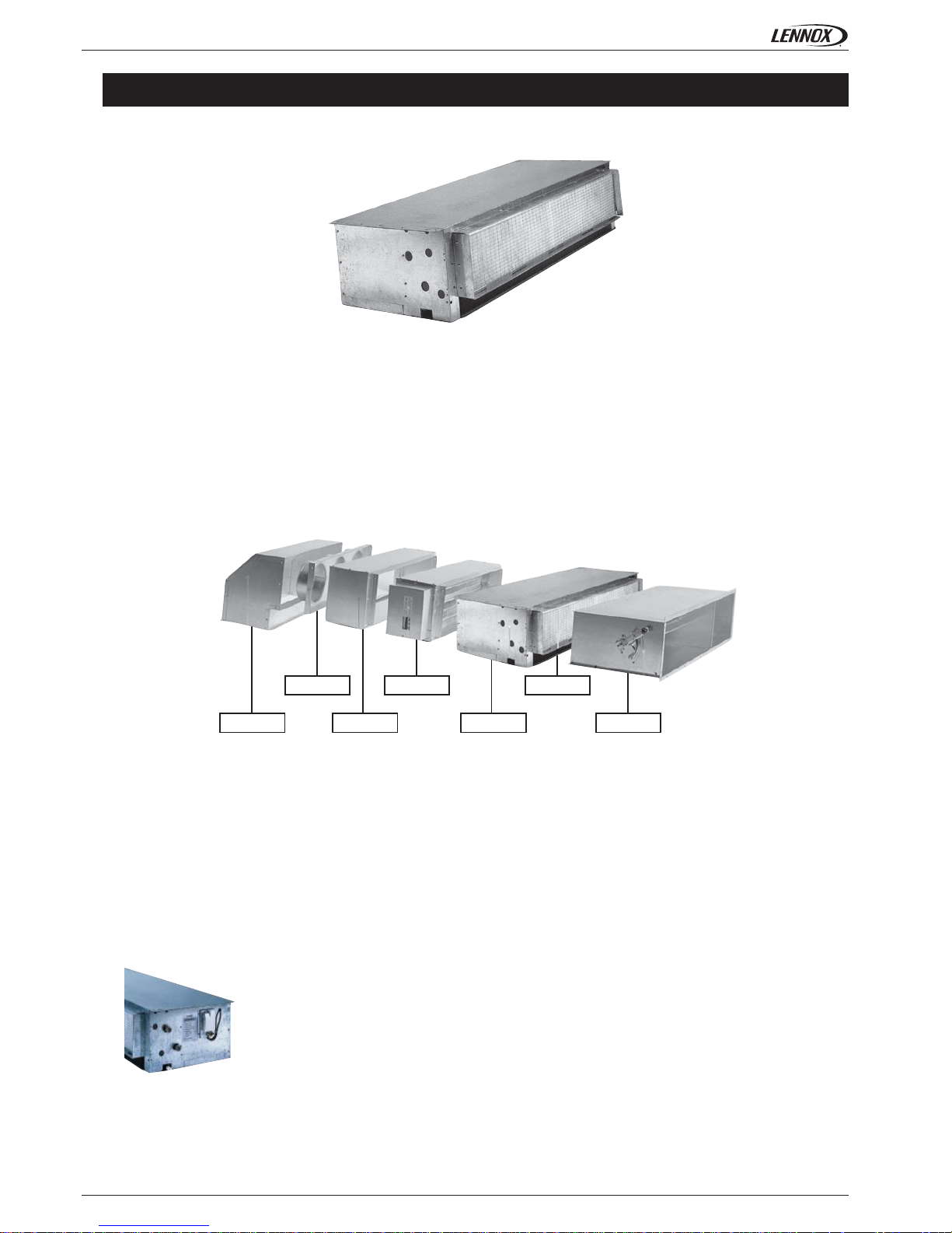
AUXILIARY DRAIN PAN
Page 29

• 27 •
HH 10 - 50
230/50 - 18
20
2
6
90
<34
66 x 44 x 60
55 x 38 x 32
±0350
HH 60 - 70
230/50 - 10,8
150
5,4
110
<34
195 x 130 x 122
Application Guide • COMFAIR HH-AGU-1107-E
CONDENSATE DRAIN PUMP
This pump is used to eliminate the condensation that collects in the tray in installations where
there is no self-emptying outlet. The pump comes with fi lter to withhold impurities, fl oat with
activation contact, suction pipe, pump body complete with control electronics and overheating
protection, wiring.
PUMP
Alarm contact normally closed that automatically cuts off the air conditioning system compressor or valve, thermal protection 90° on
the pump coil, electrical connection by plug (delivered with 1 m cable), rubber mounting bracket included, ...
AVANTAGES
Small size, low noise level.
ACCESSORIES - HH
This pump is used to eliminate the condensation that collects in the tray in installations where
there is no self-emptying outlet.
Main supply V/Hz - W
Max. fl ow rate l/h
Max. suction head m
Max. discharge head m
Alarm contact NC 8 A resistive
Thermal protection (overheat) °C
Sound level at 1 m dB(A)
Pump dimensions (Lxlxh) mm
Detection unit dimensions (Lxlxh) mm
Weight (including box) kg
Main supply V/Hz - A
Max. fl ow rate l/h
Max. suction head m
Alarm contact NC 4 A resistive
Thermal protection (overheat) °C
Sound level dB(A)
Pump dimensions mm
Page 30

• 28 •
Application Guide • COMFAIR HH-AGU-1107-E
CONTROLLERS
GENERAL DESCRIPTION
CD2X6
Wall mounted - 3 digits display
On/Off - Heating/Cooling - 3 speeds
Ambiant temperature knob adjustment
RCE 10E
Wall mounted
On/Off - Heating/Cooling - 3 speeds
Ambiant temperature knob adjustment
Wall mounted
CD2X6 RCE10E
Characteritics
On/Off
Manual speed control
Automatic fan control
Manual Heating/Cooling control
Automatic Heating/Cooling control
Temperature setting knob
External centralised contact
Windows contact
Digital display
On/Off valve control
Modulating valve control
Available for
2 pipes
2 pipes + electrical heater
4 pipes
Page 31

Page 32

lennoxemeia.com
+7 495 626 56 53
+34 902 533 920
+38 044 585 59 10
+44 1604 669 100
+ 32 3 633 3045
+33 1 64 76 23 23
+49 (0) 40 589 6235 0
+ 39 02 495 26 200
+ 31 332 471 800
+48 22 58 48 610
+351 229 066 050
LENNOX DISTRIBUTION
+33 4 72 23 20 00
RUSSIA
SPAIN
UKRAINE
UNITED KINGDOM AND IRELAND
BELGIUM AND LUXEMBOURG
FRANCE
GERMANY
ITALY
NETHERLANDS
POLAND
PORTUGAL
Due to Lennox’s ongoing commitment to quality, the specifi cations,
ratings and dimensions are subject to change without notice and
without incurring liability.
Improper installation, adjustment, alteration, service or
maintenance can cause property damage or personal injury.
Installation and service must be performed by a qualifi ed installer
and servicing agency
SALES OFFICES :
OTHER COUNTRIES :
COMFAIR HH-AGU-1107-E
 Loading...