

Page 1
Application guide
COMFAIR
440 - 860 m3/h
HD High wall fan coil unit
COMFAIR HD-AGU-1107-E
Page 2

Page 3
TABLE OF CONTENTS
COMFAIR HD
High wall fan coil units
APPLICATION GUIDE
HIGH WALL FAN COIL UNITS - HD
Ref : COMFAIR HD-AGU-1107-E
General description . . . . . . . . . . . . . . . . . . . . . . . . . . . . . . . . . . . . . . . . . . . . . . .2
General data - Eurovent Conditions . . . . . . . . . . . . . . . . . . . . . . . . . . . . . . . . . . .3
Installation . . . . . . . . . . . . . . . . . . . . . . . . . . . . . . . . . . . . . . . . . . . . . . . . . . . . . . 4
CONTROLLERS
General description . . . . . . . . . . . . . . . . . . . . . . . . . . . . . . . . . . . . . . . . . . . . . . .8
The COMFAIR HD LENNOX fan coil units are tested and rated in accordance with Eurovent certifi cation program.
Our company is a member of the Eurovent Certifi cation Program.
Our products comply with the European standards.
Product designed and manufactured under a quality management system certifi ed ISO 9001.
All the technical and technological information contained in this manual, including any drawing and technical descriptions provided
by us, remain the property of Lennox and must not be utilised (except in operation of this product), reproduced, issued to or made
available to third parties without the prior written agreement of Lennox.
• 1 •Application Guide • COMFAIR HD-AGU-1107-E
Page 4
GENERAL - HD
HIGH WALL FAN COIL UNITS - HD
Comfair HD fan coil units are similar in design and use to the widely
used DX high-wall mini-split systems. With a maximum width of only
210mm, the casing is manufactured from high quality plastic and
is of an aesthetically pleasing design to compliment almost every
environment.
«A BREATH OF FRESH AIR»
The fan is of a Tangential type running at low speed to guarantee
low noise levels. The concept of air discharge from the unit allows
effi cient distribution of the treated air for maximum comfort, and
simplicity of use. HD units are equipped with a system of automatic horizontal air defl ection through an arc of 35° in cooling operation
(10° in heating operation), which avoids stratifi cation of the airstreams. When the unit stops, the defl ector blades close automatically,
which serves not only to protect the internal components against dust but also preserves the
neat aesthetic appearance of the unit.
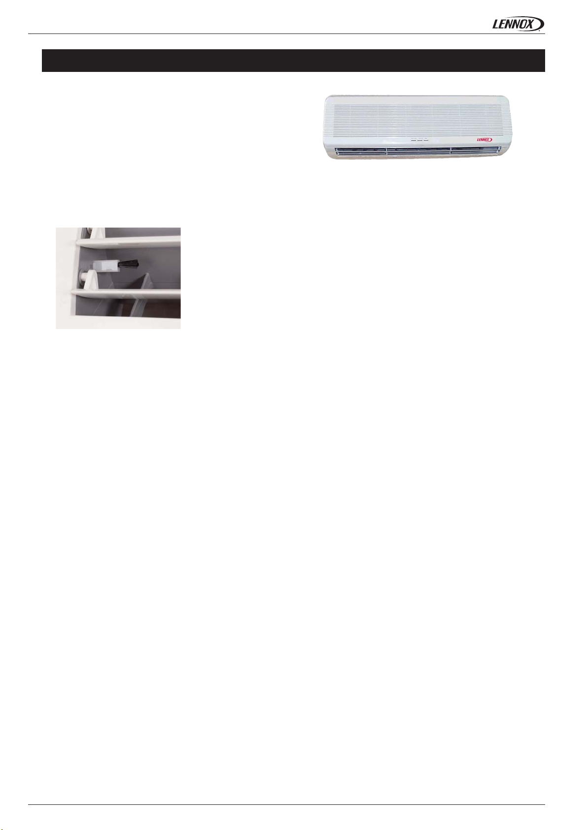
FILTRATION AND AIR QUALITY
The Comfair HD units not only control the temperature of the air but also the air quality in the
conditioned space. Each unit is fi tted with a fi lter and an Ioniser which produces negatively
charged ions which attracts the positively charged dust particles and neutralises harmful
microbes present in the atmosphere. The Ioniser comprises of a small generator, which transmits
an intermittent high voltage to carbon fi bres situated in the airstream.
COILS
Each unit contains a chilled and hot water coil manufactured from copper tubes with aluminium fi ns. Water connections are female gas
½» and each coil is fi tted with an air vent. A water temperature sensor prevents low temperature discharge.
REMOTE CONTROLLER
The infa-red remote controller offers the same functions as a DX split system. It includes an LCD display which indicates the status
and set points of the unit. Sixteen buttons allow fast and easy control of the operation of all functions of the unit.
• 2 • Application Guide • COMFAIR HD-AGU-1107-E
Page 5

GENERAL DATA - EUROVENT CONDITIONS - HD
All data are at Eurovent conditions.
http://www.eurovent-certifi cation.com/
PROGRAM: FC-2-H
COMFAIR HD
Min
Sensible cooling capacity kW
Total cooling capacity kW
Heating capacity kW
Water pressure drops in cooling kPa
Water pressure drops in heating kPa
Fan electrical power kW
Voltage V/Ph/Hz -
Sound power level dB(A)
Med
Max
Min
Med
Max
Min
Med
Max
Min
Med
Max
Min
Med
Max
Min
Med
Max
Min
Med
Max
123
1,2 1,55 2,89
1,45 1,7 3,32
1,7 1,99 3,44
1,45 1,87 3,71
1,73 2 4,2
2,04 2,46 4,42
1,81 2,21 4,51
2,22 2,42 5,24
2,59 3,32 5,64
9,1 16 48,1
13 18 61,4
18 20 68,1
8,4 14 42,2
12 16 54
16,7 17 59,8
0,02 0,02 0,05
0,03 0,03 0,05
0,03 0,03 0,06
230/1/50
49 46 50
52 50 57
54 54 61
Application Guide • COMFAIR HD-AGU-1107-E
• 3 •
Page 6

INSTALLATION - HD
INSTALLATION WITH SIMPLE MOUNTING PLATE
The method of installing the wall-mounted water-fi lled fan coil of the HD range is shown below. Take into account the following:
- Looking at the unit from the front, the supply pipes go from right to left.
- The system pipes must come from the left.
SYSTEM
WATER PIPES
100
SYSTEM
WATER PIPES
60
320
1
Make suffi cient large hoel in the wall for the system water pipes
to pass through.
3
MOUNTING PLATE
MOUNTING PLATE
Fix the fan coil mounting plate to the wall.
2
Put the fan coil back to its position of operation
SIZE OF WATER AND CONDENSATE DRAIN FITTINGS
500
B
490
157
A
6
7
HD1 AND HD2
HOSE
Take two hoses with 1/2" fi tting and connect to the systems pipes.
These pipes must be lagged.
4
HD
Anchor the fan coil to the mouting plate
5
A
15
25
Ø 16,5
A: Hoses for water connection Ø 1/2"
B: Condensate drain pipe Ø 16,5 mm
550
500
HD3
B
400
Tilt the fan coil and insert the relative polystyrene foam spacer and
then carry out the water connections
• 4 •
Application Guide • COMFAIR HD-AGU-1107-E
Page 7

INSTALLATION - HD
INSTALLATION WITH BUILT-IN VALVES
Important! It is recommended that wall-mounted water-fi lled fan coils are
installed with ON/OFF devices.
7
8
9
OUT
IN
1: Supply pipe (return)
2: Supply pipe (delivery)
3: Condensate drain pipe
4: Clamp for fi xing the condensate drain/connecting pipe
5: Condensing collecting tray
6: Condensate outlet
7: Fan coil anchoring plate
8: Screws for mounting plate assembly
9: Valve body
6
345 21
From HD
To HD
2. Cover the bottom edge of the niche with a steel angle bar
(NOT supplied). Apply the mounting plate and fi x it using four
screws and four screw anchors in the relative holes:
9-10 mm
ANGLE BAR
3. Fix the condensate collecting tray by inserting two self-tapping
screws into the relative holes. The external surface of the tray must
be fl ush with the wall:
Proceed as shown bellow to assemble the mounting plate.
235
CAUTION! Check that the highlighted measurement is exact
1. Identify the position on the wall where the fan coil is to be installed
and create a niche with the dimensions shown bellow:
4. Position the fan coil on the mounting plate:
5. Tilt the fan coil and insert the relative polystyrene foam spacer
so that the valves can be easily reached and connected to the
appliance and to the mains water supply:
370
50
200
100
Application Guide • COMFAIR HD-AGU-1107-E
6. Connect the hoses to the fan coil supply pipes and the condensate
65
drain hose:
• 5 •
Page 8

INSTALLATION - HD
INSTALLATION WITH BUILT-IN
VALVES - CONT’D
7. Connect the valve to the connecting hoses:
8. Fix the bracket for securing the condensate drain hose and the
connecting hoses on the condensate collecting tray:
INSTALLATION WITH VALVES
AND OUTER FRAME
Proceed as shown bellow to assemble the mouting plate:
IMPORTANT! It is recommended that wall-mounted water-fi lled fan coils
are installed with ON/OFF devices.
1. Mark the position on the wall where the fan coil is to be installed,
then apply the mounting plate and fi x it with two screws and
screws anchors in the relative holes.
9. Fix the condensate drain hose with silicone:
10. Replace the fan coil in its original position.
CAUTION! The condensate collecting tray must be fi xed so that it slopes
gently downward towards the condensate drain outlet:
N.B.:
- Do not bend or damage the enclosed mounting plate
- Comply with the highlighted measurements (previous page)
- The base of the enclosed mounting plate must project by 9-10 mm
from the wall
- The condensate collecting tray must always be fl ush with the wall.
2. Position the cross rail of the frame (A) on top of the mounting
plate previously fi xed to the wall.
A
Fix to the wall
with screws
Fix to the wall
with screws
Fix to the wall
with threaded
bars
N.B. In model 3, the threaded bars are locked onto the MOUNTING PLATE
with nut and check nut.
HD1 AND HD2
A
HD3
3. Fix the extension (B) to the cross rail with the 4 self-tapping
screws provided in the kit:
• 6 •
HD1 AND HD2
B
Application Guide • COMFAIR HD-AGU-1107-E
Page 9

INSTALLATION - HD
INSTALLATION WITH VALVES AND OUTER FRAME - CONT’D
4. Final result:
HD3
HD1 AND HD2
HD3
A
B
5. Repeat points 4, 5, 6, 7, and 8 of the previous section (Installtaion with built-in valves)
Application Guide • COMFAIR HD-AGU-1107-E
• 7 •
Page 10

CONTROLLERS
GENERAL DESCRIPTION
CD2X6
Wall mounted - 3 digits display
On/Off - Heating/Cooling - 3 speeds
Ambiant temperature knob adjustment
Characteritics
On/Off
Manual speed control
Automatic fan control
Manual Heating/Cooling control
Automatic Heating/Cooling control
Temperature setting knob
External centralised contact
Windows contact
Digital display
On/Off valve control
Modulating valve control
Available for
2 pipes
2 pipes + electrical heater
4 pipes
RCE 10E
Wall mounted
On/Off - Heating/Cooling - 3 speeds
Ambiant temperature knob adjustment
Wall mounted
CD2X6 RCE10E
• 8 •
Application Guide • COMFAIR HD-AGU-1107-E
Page 11

Page 12
SALES OFFICES :
www.lennoxeurope.com
BELGIUM AND LUXEMBOURG
+ 32 3 633 3045
FRANCE
+33 1 64 76 23 23
GERMANY
+49 (0) 40 589 6235 0
ITALY
+ 39 02 495 26 200
NETHERLANDS
+ 31 332 471 800
POLAND
+48 22 58 48 610
RUSSIA
+7 495 626 56 53
SPAIN
+34 902 533 920
UKRAINE
+380 44 461 87 79
UNITED KINGDOM AND IRELAND
+44 1604 669 100
OTHER COUNTRIES :
PORTUGAL
+351 229 066 050
COMFAIR HD-AGU-1107-E
LENNOX DISTRIBUTION
+33 4 72 23 20 00
Due to Lennox’s ongoing commitment to quality, the specifi cations, ratings and dimensions are subject
to change without notice and without incurring liability.
Improper installation, adjustment, alteration, service or maintenance can cause property damage or
personal injury.
Installation and service must be performed by a qualifi ed installer and servicing agency
 Loading...