

Lennox CMC 025S, CMH 020S, CMH 025S, CMH 035S, CMC 040S Installation, Operating And Maintenance Manual
...Page 1
lennoxemeia.com
COMPACTAIR
CMC - CMH
Installation,
operating
and maintenance
manual
Vertical packaged air conditioner
Packaged unit
20 à 100 kW
MIL123E-0613 11-2014
Translation of original manual
Page 2

1
4
4-5
5
6
6-8
9
10
11-14
15-16
17
17
18
19
20
20
21-22
23-26
27
28-29
30
31
32
2.- INSTALLATION PAGE
3.- COMMISSIONING AND OPERATION PAGE
4.- MAINTENANCE PAGE
DATA PAGE FOR COMMISSIONING UNIT PAGE 3
TABLE OF CONTENTS
POINTS TO BEAR IN MIND PAGE 2
1.- GENERAL CHARACTERISTICS PAGE
1.1.- PHYSICAL DATA
1.2.- ELECTRICAL DATA
1.3.- OPERATING LIMITS
1.4.- INDOORFAN PERFORMANCES
1.5.- RETURN FAN PERFORMANCES
1.6.- OPTION PRESSURE DROP
1.7.- OUTDOO FAN PERFORMANCES
1.8.- PIPING DRAWINGS
1.9.- UNIT DIMENSIONS
2.1.- PRELIMINARY PREPARATIONS
2.2.- UNIT ACCEPTANCE
2.3.- OPTIONAL OPERATIONS PRIOR TO UNIT INSTALATION
2.4.- UNIT LOCATION
2.5.- INSTALLATION CLEARANCES
2.6.- DRAINS
2.7.- ELECTRICAL CONNECTIONS
2.8.- OPTIONS INSTALLATION
3.1.- PRELIMINARY CHECKS BEFORE FIRST INSTALLATION
3.2.- PRELIMINARY CHECKS AT FIRST INSTALLATION
4.1.- PREVENTIVE MAINTENANCE
4.2.- CORRECTIVE MAINTENANCE
4.3.- FAILURE DIAGNOSIS
Lennox have been providing environmental solutions since 1895, our COMPACTAIR range continues to meet the standards that have made LENNOX a household name. Flexible design solutions to meet YOUR needs and uncompromising attention to detail. Engineered to last, simple to maintain and Quality that comes as standard.
For information on local contacts at www.lennoxeurope.com.
The manufacturing of these units is made under the requirements of the ISO 9001 and ISO 14001.
All the technical and technological information contained in this manual, including any drawing and technical descriptions provided by us, remain the property of Lennox and must not be used (except in the operation of this product),
reproduced, issued to or made available to third parties without the prior written agreement of Lennox.
WARNING: Read this manual before installation, reparation o maintenance works.
Page 3
2
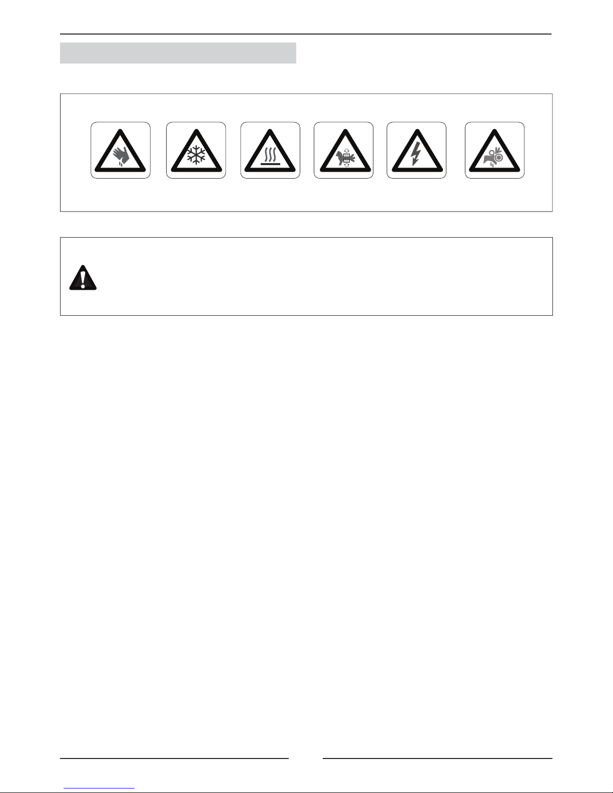
Abrasive
surfaces
Risk of injury by
moving objects
High
temperatures
Low
temperatures
Risk of injury by
rotating objects
Electrical
voltage
ELECTRICAL CONNECTIONS
Make sure to switch off the power before installing, repairing or carrying out maintenance on the unit,
in order to prevent serious electrical injury.
Keep local and national legislation in mind when installing the unit.
Standard Guidelines to Lennox equipment
All technical data contained in these operating instructions, including the diagrams and technical description remains
the property of Lennox and may not be used (except for the purpose of familiarizing the user with the equipment),
reproduced, photocopied, transferred or transmitted to third parties without prior written authorization from Lennox.
The data published in the operating instructions is based on the latest information available. We reserve the right to
make modifi cations without notice.
We reserve the right to modify our products without notice without obligation to modify previously supplied goods.
These operating instructions contain useful and important information for the smooth operation and maintenance of
your equipment.
The instructions also include guidelines on how to avoid accidents and serious damage before commissioning the
equipment and during its operation and how to ensure smooth and fault-free operation. Read the operating instructions
carefully before starting the equipment, familiarize yourself with the equipment and handling of the installation and
carefully follow the instructions. It is very important to be properly trained in handling the equipment. These operating
instructions must be kept in a safe place near the equipment.
Like most equipment, the unit requires regular maintenance. This section concerns maintenance and management
personnel.
If you have any queries or would like to receive further information on any aspect relating to your equipment,
do not hesitate to contact us.
POINTS TO BEAR IN MIND
DANGER AND WARNING SIGNS
Page 4
3
1 ºC
2 ºC
1 ºC
2 ºC
1 ºC
2 ºC
1 ºC
2 ºC
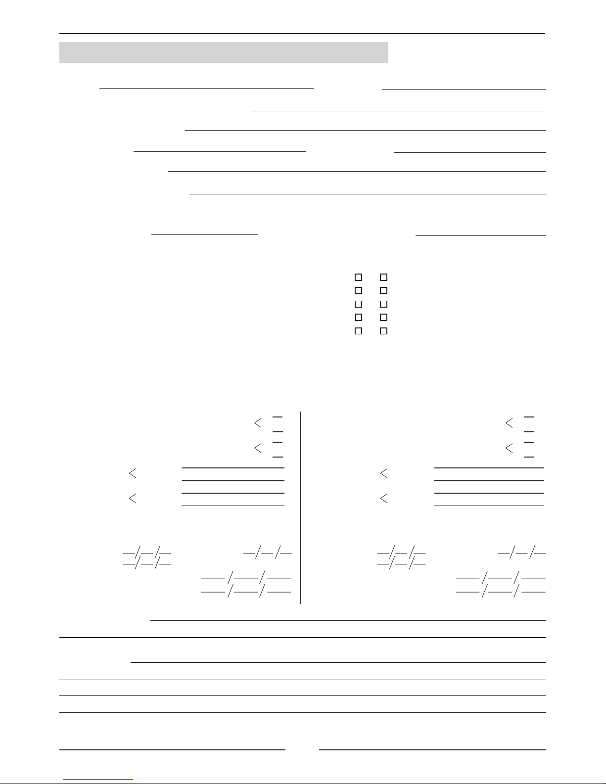
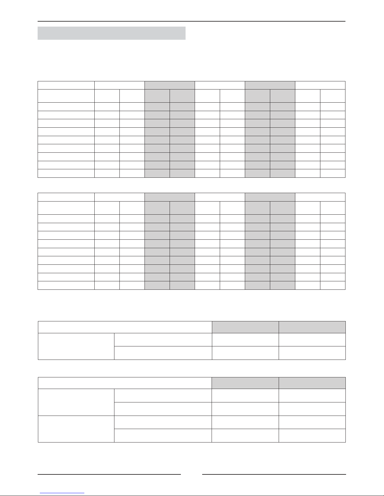
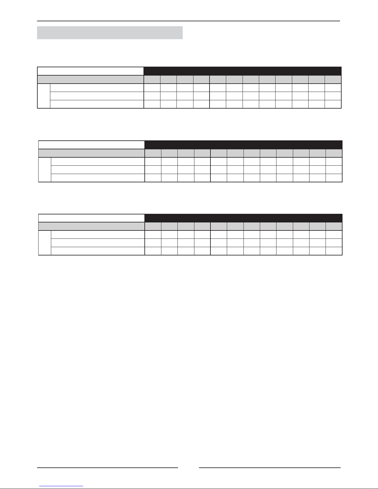
DATA PAGE FOR UNIT COMMISSIONING
UNIT:
INSTALLER TEL:INSTALLER:
CONTROL PANEL IDENTIFICATION CODE:
INSTALLATION ADDRESS:
SERIAL Nr:
CHECKS:
DATE OF COMMISSIONING:
SUPPLY VOLTAGE:
RATED VOLTAGE OF THE UNIT:
UNIT ON SHOCK ABSORBERS
DRAINAGE WITH TRAP
MAIN POWER SUPPLY CONNECTION
CONTROL PANEL CONNECTION
COMPRESSOR OIL LEVEL INDICATOR
YES NO
DATA INPUT:
COOLING CYCLE
Air intake temperature to the outdoor coil:
Air output temperature to the outdoor coil:
High pressure:
Low pressure:
circuit 1
circuit 2
circuit 1
circuit 2
Air intake temperature to the outdoor coil:
Air output temperature to the outdoor coil:
High pressure:
Low pressure:
circuit 1
circuit 2
circuit 1
circuit 2
HEATING CYCLE
ELECTRIC POWER CONSUMPTION (Amps)
Compressor 1
Compressor 3
Outdoor fan section 1
Outdoor fan section 2
Options installed:
Comments:
Compressor 2
Compressor 2
INSTALLER ADDRESS:
Compressor 1
Compressor 3
Outdoor fan section 1
Outdoor fan section 2
Page 5
4
C M C 020 S N M 3 M
CMC
CMH
020S
CMC
CMH
025S
CMC
CMH
030S
CMC
CMH
035S
CMC
CMH
040S
CMC
CMH
045D
CMC
CMH
055D
CMC
CMH
070D
CMC
CMH
085D
CMC 4300 5350 6000 7800 9000 5150 6100 7750 9250
CMH 4500 5500 6200 8050 9300 5300 6300 8000 9550
371 407 418 510 533 623 779 824 876
376 412 424 516 539 630 785 831 883
2 2 2 2 2 2 2 3 3
10 10 10 10 10 20 20 20 30
50 50 50 75 75 75 165 165 165
10 10 10 12 16 20 20 24 30
6.5 3 3 5 0 3 3 3 13
6.5 3 8 8 3 6 6 16 21
9.5 8 11 8 6 6 19 24 21
25 25 25 28 28 28 37
(1)
37
(1)
37
(1)
2 2 2 2 2 3 4 4 7
6 6 6 9 9 9 14 14 14
2 6 6 4 4 12 12 8 8
CMC
CMH
020S
CMC
CMH
025S
CMC
CMH
030S
CMC
CMH
035S
CMC
CMH
040S
CMC
CMH
045D
CMC
CMH
055D
CMC
CMH
070D
CMC
CMH
085D
8.25 10.1 11.8 15.5 16.9 20.2 23.5 31 33.8
1.45 1.89 2.69 2.69 2.69 3.63 5.38 5.38 7.26
0.74 1.45 1.45 1.89 2.69 2.69 2.69 3.63 5.06
10.44 13.44 15.94 20.08 22.28 26.52 31.57 40.01 46.12
15 21 22 25.6 31 42 44 51.2 62
2.59 3.45 4.8 4.8 4.8 6.48 9.6 9.6 12.96
1.4 2.59 2.59 3.45 4.8 4.8 4.8 6.48 8.6
18.99 27.04 29.39 33.85 40.6 53.28 58.4 67.28 83.56
89.8 100.4 107.7 142.6 157.5 126.6 136.7 176 200.5
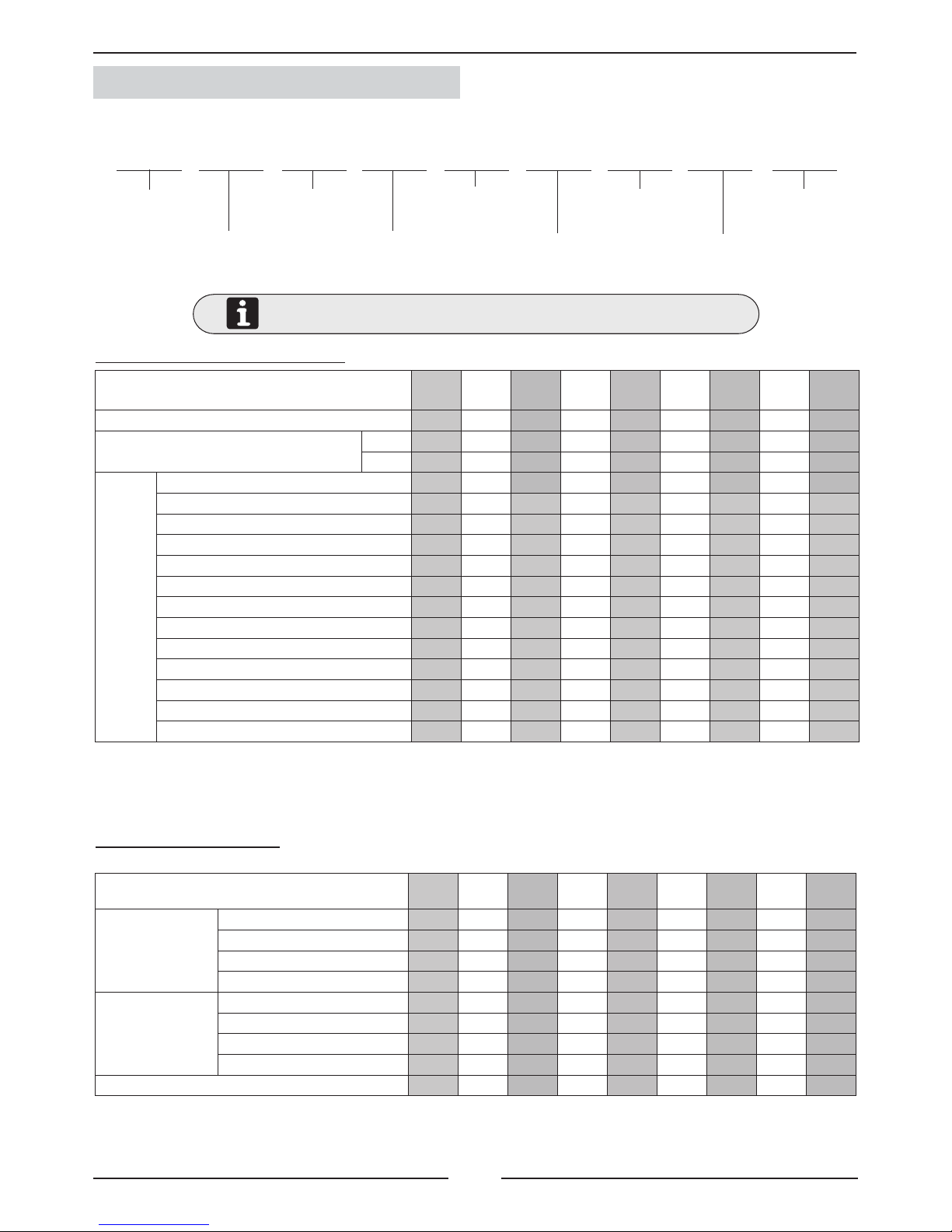
1.- GENERAL CHARACTERISTICS
1.1.- PHYSICAL DATA
Unit
COMPACTAIR
C: Cooling only
H: Heat pump
Type of refrigerant
M: R-410A
Approximate cooling
capacity in kW
M: Compact unit
S: One Circuit
D: Two Circuits
- - -
Number
of revision
M: 400V/3/50
CMC: Cooling only unit R-410A.
CMH: Heat pump unit R-410A.
(1)
Weight of free-cooling and exhaust fan.
UNIDAD MODELOS
Compressor (Nr/Type) 1/Scroll 1/Scroll 1/Scroll 1/Scroll 1/Scroll 2/Scroll 2/Scroll 2/Scroll 2/Scroll
Refrigerant R-410A charge (per circuit)
Net weight
Kg.
CMC cooling only unit
CMH heat pump unit
Air sock control
Electtrical heater
Free-cooling
Hot water coil
Kit fan HP1
Kit fan HP2
Kit fan HP2
Exhaust fan
Low noise
High ! ltration level (G4 pre! ltre / F7 ! ltration)
Kit long distance
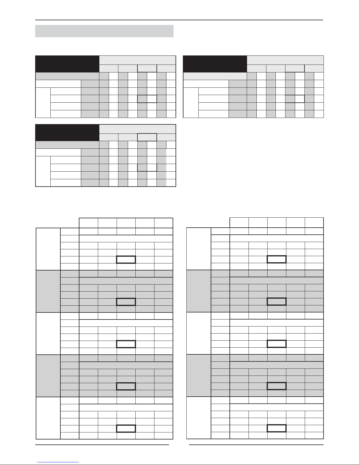
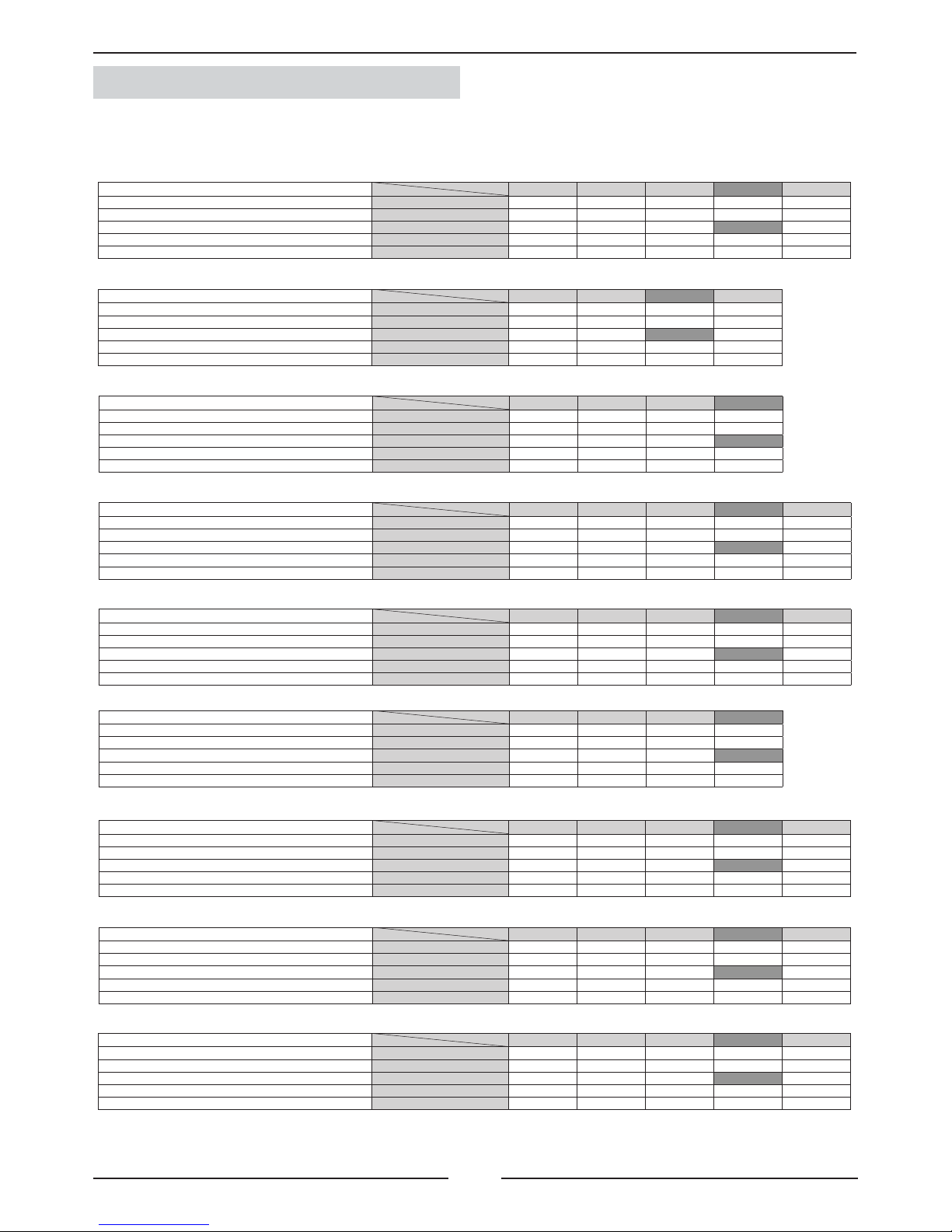
1.2.- ELECTRICAL DATA
ELECTRICAL CONSUMPTION
(*) The units are supplied with refrigerant R-410A indicated above.
UNIT MODELS
Maximum
absorbed
power
(Kw)
Compressor
Fun motor outdoor
Fun motor indoor
Total power
Maximum
current
(A)
Compressor
Fun motor outdoor
Fun motor indoor
Total current
Start up current (A)
WEIGHTS OF THE UNITS AND OPTIONS
Page 6
5
CIC/H 020S CIC/H 025S CIC/H 030S CIC/H 035S CIC/H 040S
0 0 0 0 0 0 0 0 0 0
0,71 1,19 0,44 0,86 44 0,86 0,8 1,35 0 0
0,71 1,19 1,24 2,21 1,24 2,21 1,74 3,03 0,94 1,68
1,15 2,05 1,24 2,21 2,18 3,89 1,74 3,03 2,37 3,8
0,51 2,6 0,51 2,6 0,51 2,6 1,33 6,8 1,33 6,8
n/a n/a n/a n/a n/a n/a n/a n/a n/a n/a
10 14,3 10 14,3 10 14,3 15 21,5 15 21,5
15 21,5 15 21,5 15 21,5 20 28,6 20 28,6
20 28,6 20 28,6 20 28,6 27 39 27 39
CIC/H 045D CIC/H 055D CIC/H 070D CIC/H 085D CIC/H 100D
0 0 0 0 0 0 0 0 0 0
0,94 1,68 0,94 1,68 1,43 2,12 1,32 2,5 1,32 2,5
2,37 3,8 2,37 3,8 2,75 4,62 3,73 6,7 5,06 8,6
2,37 3,8 3,69 3,69 5,16 8,82 3,73 6,7 5,06 8,6
1,33 6,8 2,65 4,5 2,65 4,5 2,65 4,5 5,3 9
n/a n/a 2,69 4,8 3,63 6,5 3,63 6,5 5,06 8,6
15 21,5
20 28,6 20 28,6 20 28,6 27 39
20 28,6
27 39 27 39 27 39 40 57,8
27 39
40 57,8 40 57,8 40 57,8 50 72,3
1.- GENERAL CHARACTERISTICS
1.2 .- ELECTRICAL DATA
Electrical consumptions to add to the unit indoor and to the set
(*) With option kit low temperature 0ºC. (**) With option kit low temperature -15ºC.
DB: Dry bulb temterature WB: Wet bulb temperature
1.3.- OPERANTING LIMITS
(*) With option kit low temperature -15ºC.
OPERATING LIMITS FOR (HEATING PUMP) UNITS MAXIMUM TEMPERATURE MINIMUM TEMPERATURES
COOLING CYCLE OPERATION
INDOOR TEMPERATURE
32ºC BS / 23ºC WH 21ºC BS / 15ºCWH
OUTDOOR TEMPERATURE
45ºC (020-025-030-045-055)
47ºC (035-040-070-085)
0ºC STANDARD UNITS
-15ºC (*)
HEATING CYCLE OPERATION
INDOOR TEMPERATURE
27ºC DB 15ºC DB
OUTDOOR TEMPERATURE
27ºC (With 20ºC outdoor tem-
perature)
-12ºC (With 20ºC indoor
temperatur)
OPERATING LIMITS FOR (COOLING-ONLY) UNITS MAXIMUM TEMPERATURES MINIMUM TEMPERATURES
COOLING CYCLE OPERATION
INDOOR TEMPERATURE
32ºC BS / 23ºC WH 21ºC BS / 15ºC WH
OUTDOOR TEMPERATURE
45ºC (020-025-030-045-055)
47ºC (035-040-070-085)
+15ºC STANDARD UNITS
0ºC (*) -15ºC (**)
Maximum
absorbed
power (Kw)
Maximum
current (A)
Maximum
absorbed
power (Kw)
Maximum
current (A)
Maximum
absorbed
power (Kw)
Maximum
current (A)
Maximum
absorbed
power (Kw)
Maximum
current (A)
Maximum
absorbed
power (Kw)
Maximum
current (A)
Ventilador interior estándar
Kit de ventilación HP1
Kit de ventilación HP2
Kit de ventilación HP3
Ventilador de extracción
Ventilador de retorno
Batería eléctrica estándar
Batería eléctrica media
Batería eléctrica alta
Maximum
absorbed
power (Kw)
Maximum
current (A)
Maximum
absorbed
power (Kw)
Maximum
current (A)
Maximum
absorbed
power (Kw)
Maximum
current (A)
Maximum
absorbed
power (Kw)
Maximum
current (A)
Maximum
absorbed
power (Kw)
Maximum
current (A)
Ventilador interior estándar
Kit de ventilación HP1
Kit de ventilación HP2
Kit de ventilación HP3
Ventilador de extracción
Ventilador de retorno
Batería eléctrica estándar
Batería eléctrica media
Batería eléctrica alta
Page 7
6
085D
14000 15125 16250 16725
ASP PI ASP PI ASP PI ASP PI
755
260 3,44 255 3,77 250 4,13
715
230 3,12 225 3,43 215 3,75 212 3,90
675
202 2,82 195 3,11 183 3,41 178 3,55
635
173 2,53 165 2,80 153 3,09 145 3,22
595
145 2,27 135 2,52 120 2,79 115 2,91
055D
9950 10825 11700 12850
ASP PI ASP PI ASP PI ASP PI
755
255 2,37 257 2,56 260 2,77 260 3,05
715
230 2,11 232 2,30 234 2,48 233 2,75
675
207 1,88 208 2,05 210 2,23 207 2,48
635
184 1,67 184 1,82 184 1,99 180 2,22
595
162 1,47 162 1,61 160 1,77 155 1,98
070D
12450 13550 14650 15090
ASP PI ASP PI ASP PI ASP PI
755
260 2,93 260 3,22 258 3,52 255 3,65
715
235 2,64 233 2,91 228 3,20 225 3,32
675
208 2,37 205 2,62 198 2,90 195 3,00
635
182 2,12 176 2,36 168 2,61 165 2,72
595
157 1,89 150 2,11 140 2,35 135 2,44
ASP (Pa):
PI (Kw):
020S
rpm
824 788 753 717 682
m3/h
3150 167 149 132 116 101
3425 162 143
127
109 93
3700 155 138 120 103 85
4100
•
127
108
90 72
025S
rpm
824 788 753 717 682
m3/h
4250 141 123 103 84 66
4625 129 109
89
69 49
5000 115 92 71 50 28
5500 89 66
42
19 n/a
030S
rpm
915 876 836 797 757
m3/h
4650 173 149 125 103 80
5050 158 133
109
84 60
5450 141 115 89 63 38
6000
•
84
56
28 0
035S
r pm
735 704 672 640 609
m3/h
6200 164 142 119 98 77
6650 153 130
106
83 61
7100 139 114 89 66 42
8050 102 75
48
22 n/a
040S
rpm
837 792 748 704 659
m3/h
6950 213 178 143 109 75
7550 196 158
122
86 50
8150 175 136 97 58 21
9050 136 94
53
10 n/a
045D
rpm 937 888 838 788 738
m3/h
7950 272 227 183 140 97
8675 249 201
155
109 63
9400
•
171 121 72 23
9750
• •
103
51 1
055D
rpm
837 792 748 704 659
m3/h
9950 206 177 148 122 96
10825 195 166
138
110 83
11700 185 154 125 97 68
12850
136
105
75 45
070D
rpm
937 888 838 788 738
m3/h
12450 237 200 163 128 95
13550
•
183
145
109 73
14650
• •
124 85 48
15090
• •
115
75 36
085D
rpm
937 888 838 788 738
m3/h
14000 202 163 125 87 51
15125 182 142
102
62 23
16250 160 117 75 34 n/a
16725 149 105
63
20 n/a
100D
rpm
750 710 670 630 591
m3/h
17350 237 202 167 133 101
18875 223 185
149
115 81
20400
•
168 131 94 59
22450
• •
100
63 25
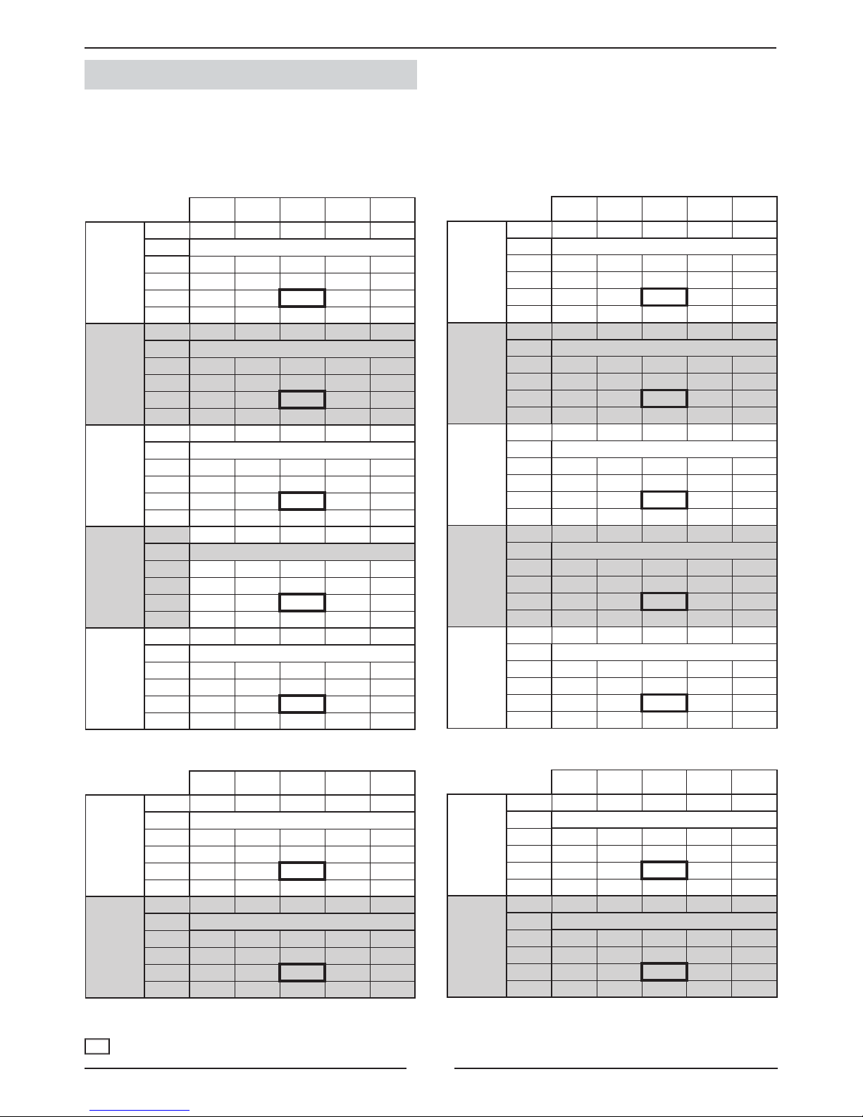
1.- GENERAL CHARACTERISTICS
Static pressure available
Absorved power
NOTA: The unit leaves factory with the pulley fi t to two
open turns
1.4.- RETURN FAN PERFORMANCES
1.5.- INDOOR FAN PERFORMANCES. STANDARD
Air fl ow (m3/h)
Return fan
(RPM)
Closed pulley
Pulley
position
1 turn
2 turns
3 vueltas
4 vueltas
Air fl ow (m3/h)
Return fan
(RPM)
Closed pulley
Pulley
position
1 turn
2 turns
3 vueltas
4 vueltas
Air fl ow (m3/h)
Return fan
(RPM)
Closed pulley
Pulley
position
1 turn
2 turns
3 vueltas
4 vueltas
CLOSED
PULLEY
1 TURN 2 TURNS 3 TURNS 4 TURNS
Available static pressure Pa.
Available static pressure Pa.
Available static pressure Pa.
Available static pressure Pa.
Available static pressure Pa.
CLOSED
PULLEY
1 TURN 2 TURNS 3 TURNS 4 TURNS
Available static pressure Pa.
Available static pressure Pa.
Available static pressure Pa.
Available static pressure Pa.
Available static pressure Pa.
Page 8
7
020S
rpm
1098 1051 1003 956 909
m3/h
3150
324 294 264 237 211
3425
321 289
261
233 207
3700
317 285 257 229 202
4100
310 279
249
222 193
025S
rpm
1098 1051 1003 956 909
m3/h
4250
308 276 246 218 190
4625
301 269
239
209 180
5000
292 260 228 197 167
5500
278 244
211
178 146
030S
rpm
1098 1051 1003 956 909
m3/h
4650
290 259 228 198 169
5050
280 248
215
184 154
5450
269 235 201 169 138
6000
249 213
178
143 109
035S
r pm
937 888 838 788 738
m3/h
6200
321 281 241 203 167
6650
313 272
232
193 155
7100
306 262 221 181 142
8050
282 236
191
148 105
040S
rpm
937 888 838 788 738
m3/h
6950
298 255 214 174 135
7550
283 240
197
155 113
8150
267 221 176 132 88
9050
•
186
138
90 43
045D
rpm 1041 986 931 876 820
m3/h
7950 371 318 267 217 168
8675 353 298
244
190 139
9400 330 271 215 158 103
9750 316 258
199
141 84
055D
rpm 1041 986 931 876 820
m3/h
9950 357 313 272 232 194
10825 349 304
263
223 185
11700
•
295 253 213 173
12850
• •
239
196 156
070D
rpm 1041 986 931 876 820
m3/h
12450 321 276 232 191 151
13550 307 262
217
174 133
14650 291 244 199 154 110
15090
•
236
190
145 101
085D
rpm 1041 986 931 876 820
m3/h
14000 288 242 197 155 112
15125 272 223
177
132 88
16250 253 203 154 107 60
16725 244 193
144
95 48
100D
rpm 837 792 748 704 659
m3/h
17350 323 279 236 196 157
18875 310 264
221
180 140
20400 296 248 204 162 121
22450
• •
178
133 90
020S
rpm
1177 1126 1075 1024 974
m3/h
3150
377 342 309 278 247
3425
373 338
306
273 243
3700
369 334 302 269 239
4100
364 329
295
263 232
025S
rpm
1318 1261 1204 1147 1091
m3/h
4250
466 423 381 341 303
4625
461 418
375
335 295
5000
•
412 368 327 287
5500
• •
•
314 273
030S
rpm 1339 1268 1197 876 1055
m3/h
4650
468 413 359 309 261
5050
462 405
352
299 250
5450
454 396 341 289 238
600
441 383
325
270 216
035S
rpm 1103 1044 986 927 869
m3/h
6200
469 414 362 313 266
6650
463 408
356
305 257
7100
458 402 348 297 247
8050
442 383
327
272 220
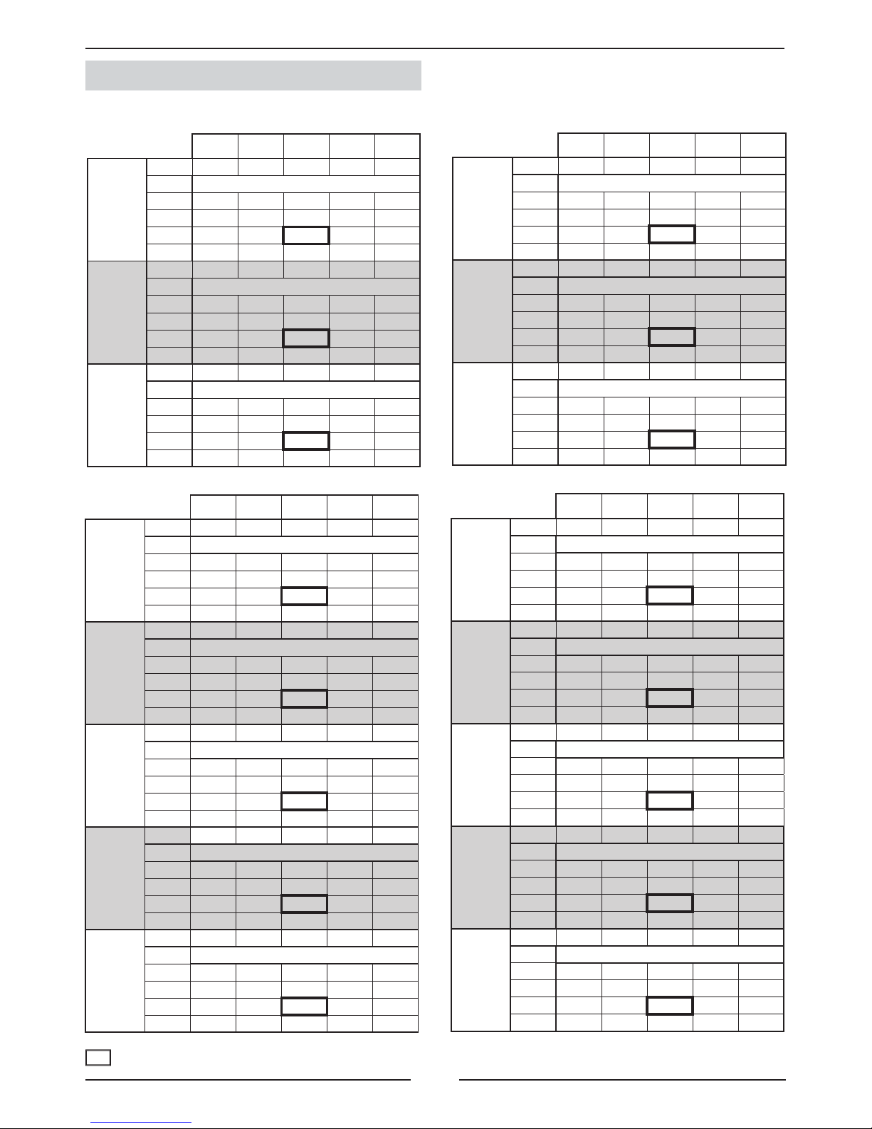
1.- GENERAL CHARACTERISTICS
1.5.- INDOOR FAN PERFORMANCES
CLOSED
PULLEY
1 TURN 2 TURNS 3 TURNS 4 TURNS
Available static pressure Pa.
Available static pressure Pa.
Available static pressure Pa.
Available static pressure Pa.
Available static pressure Pa.
CLOSED
PULLEY
1 TURN 2 TURNS 3 TURNS 4 TURNS
Available static pressure Pa.
Available static pressure Pa.
Available static pressure Pa.
Available static pressure Pa.
Available static pressure Pa.
VENTILATION HP1
VENTILATION HP2
CLOSED
PULLEY
1 TURN 2 TURNS 3 TURNS 4 TURNS
Available static pressure Pa.
Available static pressure Pa.
CLOSED
PULLEY
1 TURN 2 TURNS 3 TURNS 4 TURNS
Available static pressure Pa.
Available static pressure Pa.
(●) WRONG STATUS ON ACCOUNT OF MOTOR POWER LIMIT.
NOTE: With low distance option it is not suitable unit working below
nominal air fl ow.
NOMINAL FACTORY SETTING.
Page 9
8
040S
rpm
1103 1044 986 927 869
m3/h
6950
449 393 340 289 239
7550
440 382
327
275 223
8150
427 370 312 257 203
9050
405 344
284
225 168
045D
rpm
1103 1044 986 927 869
m3/h
7950
432 373 317 263 211
8675
415 355
296
240 184
9400
395 332 271 211 152
9750
384 320
256
195 134
055D
rpm
1172 1109 1047 985 923
m3/h
9950
514 456 399 346 296
10825
508 448
391
338 286
11700
500 440 383 328 275
12850
• •
369
313 258
070D
rpm 1172 1109 1047 985 923
m3/h
12450 371 421 363 307 252
13550 470 408
348
289 233
14650 457 391 329 268 208
15090 450 383
320
258 196
085D
rpm 1172 1109 1047 985 923
m3/h
14000 452 390 328 268 211
15125 438 371
307
245 183
16250 418 349 282 215 150
16725 408 338
270
202 135
100D
rpm 937 888 838 788 738
m3/h
8675 477 419 364 312 262
9437 469 410
354
299 248
10200 458 398 341 284 232
11225 440 379
319
261 206
020S
rpm
1318 1261 1204 1147 1091
m3/h
3150
483 438 397 357 319
3425
478 434
393
353 316
3700
474 430 389 349 312
4100
469 425
383
343 305
025S
rpm
1500 1420 1340 1261 1181
m3/h
4250
•
550 485 423 365
4625
•
545
480
418 359
5000
•
541 475 412 352
5500
•
532
466
402 339
030S
rpm
1500 1420 1340 1261 1181
m3/h
4650
•
535 469 408 349
5050
•
529
463
399 340
5450
•
521 455 391 330
6000
•
511
443
376 313
035S
r pm
1250 1183 1117 1051 985
m3/h
6200
•
548 483 421 362
6650
•
545
478
415 355
7100
•
539 472 408 347
8050
•
526
456
390 326
040S
rpm
1250 1183 1117 1051 985
m3/h
6950
602 530 463 399 339
7550
594 522
453
388 326
8150
586 512 442 376 311
9050
570 493
421
351 283
045D
rpm 1250 1183 1117 1051 985
m3/h
7950
589 515 446 381 317
8675
578 501 430 363 295
9400
562 485 411 340 270
9750
553 475 400 326 255
055D
rpm 1339 1268 1197 1126 1055
m3/h
9950 689 612 539 471 406
10825 683 606 533 464 398
11700 677 599 525 457 390
12850
670 590 515 444 376
070D
rpm 1339 1268 1197 1126 1055
m3/h
12450
662 582 508 437 370
13550 652 573
497
424 354
14650 641 561 484 408 336
15090 636 555
477
400 328
085D
rpm 1339 1268 1197 1126 1055
m3/h
14000
636 557 478 406 336
15125 623 542
464
387 315
16250 609 526 445 367 289
16725 602 518
436
357 279
100D
rpm 1041 986 931 876 820
m3/h
8675
606 537 469 407 346
9437 599 529
461
396 334
10200 592 519 451 384 321
11225
•
504
433
364 299
1.- GENERAL CHARACTERISTICS
1.5.- INDOOR FAN PERFORMANCES. VENTILATION HP2
(●) WRONG STATUS ON ACCOUNT OF MOTOR POWER LIMIT.
NOTE: With low distance option it is not suitable unit working below
nominal air fl ow.
NOMINAL FACTORY SETTING.
CLOSED
PULLEY
1 TURN 2 TURNS 3 TURNS 4 TURNS
Available static pressure Pa.
Available static pressure Pa.
Available static pressure Pa.
CLOSED
PULLEY
1 TURN 2 TURNS 3 TURNS 4 TURNS
Available static pressure Pa.
Available static pressure Pa.
Available static pressure Pa.
CLOSED
PULLEY
1 TURN 2 TURNS 3 TURNS 4 TURNS
Available static pressure Pa.
Available static pressure Pa.
Available static pressure Pa.
Available static pressure Pa.
Available static pressure Pa.
CLOSED
PULLEY
1 TURN 2 TURNS 3 TURNS 4 TURNS
Available static pressure Pa.
Available static pressure Pa.
Available static pressure Pa.
Available static pressure Pa.
Available static pressure Pa.
VENTILATION HP3
Page 10
9
020S 025S 030S
3150 3425 3700 4100 4250 4625 5000 5500 4650 5050 5450 6000
13 17 20 25 24 31 37 45 28 37 43 54
85 93 102 115 120 133 146 165 133 148 163 184
15 17 20 23 25 28 32 38 29 33 37 44
035S 040S 045D
6200 6650 7100 8050 6950 7550 8150 9050 7950 8675 9400 9750
26 30 34 43 33 38 44 52 42 48 55 58
128 140 152 178 148 164 181 208 175 197 219 230
25 29 32 39 31 35 40 47 38 44 50 54
055D 070D 085D
9950 10825 11700 12850 12450 13550 14650 15090 14000 15125 16250 16725
11 13 16 19 18 21 24 26 22 26 30 32
123 136 150 169 162 181 200 208 188 209 230 239
24 27 31 36 34 39 44 47 41 47 53 55
1.- GENERAL CHARACTERISTICS
1.6.- OPTION PRESSURE DROP (Pa)
Unit models
Airfl ow (m3/h)
Options
Free-cooling
High effi ciency fi lter
Hot water coil
Unit models
Caudal de aire (m3/h)
Options
Free-cooling
High effi ciency fi lter
Hot water coil
Unit models
Airfl ow (m3/h)
Options
Free-cooling
High effi ciency fi lter
Hot water coil
Page 11
10
055D
7000 8000 9000 10000 10700
741 299 264 225 160 96
709 271 235 195 137 83
677 242 206 165 113 70
645 213 178 135 73 57
613 184 149 105 32 44
070D
7350 8400 9450 10500 11200
741 272 230 182 122 66
709 243 201 153 98 50
677 213 172 124 74 33
645 184 142 95 44 16
613 154 113 66 13 -0.4
085D
7700 8800 9900 11000 11750
751 277 235 187 126 69
719 247 199 159 101 51
686 208 162 120 71 36
654 181 139 89 24 15
621 154 112 65 12 n/a
020S
5300 6100 6850 7600 8100
751 178 156 134 104 77
719 162 140 118 89 64
686 141 118 96 67 38
654 124 101 78 47 6
621 108 86 64 35
(rpm)
(m3/h)
025S
5950 6800 8500 9100
841 223 195 126 91
805 202 174 107 74
769 177 148 88 44
732 154 125 63 7
696 135 107 40 4
(rpm)
(m3/h)
030S
7000 8000 9000 10000
934 272 234 194 142
894 246 208 168 117
854 213 175 134 84
814 186 146 106 55
773 161 123 82 36
(rpm)
(m3/h)
035S
8400 9600 10800 12000 12850
741 209 191 171 146 125
709 189 171 152 126 105
677 168 151 132 107 87
645 148 131 112 88 68
613 128 111 92 69 50
(rpm)
(m3/h)
040S
8200 9350 10525 11700 12500
741 205 188 170 148
709 185 168 150 128 110
677 163 146 128 106 89
645 143 127 109 87 68
613 126 110 91 69 51
(rpm)
(m3/h)
045D
9800 11200 12600 14000
829 237 213 183 136
794 235 187 156 111
758 233 161 130 86
722 231 135 104 72
686 229 109 77 57
(rpm)
(m3/h)
(rpm)
(m3/h)
(rpm)
(m3/h)
(rpm)
(m3/h)
•
•
1.- GENERAL CHARACTERISTICS
Closed pulley
1 turn
2 turns
3 turns
4 turns
Closed pulley
1 turn
2 turns
3 turns
4 turns
Closed pulley
1 turn
2 turns
3 turns
4 turns
Closed pulley
1 turn
2 turns
3 turns
4 turns
Closed pulley
1 turn
2 turns
3 turns
4 turns
Closed pulley
1 turn
2 turns
3 turns
4 turns
Closed pulley
1 turn
2 turns
3 turns
4 turns
Closed pulley
1 turn
2 turns
3 turns
4 turns
Closed pulley
1 turn
2 turns
3 turns
4 turns
1.7.- OUTDOOR FAN PERFORMANCE (Pressure available Pa)
STANDARD UNITS WITHOUT OPTIONS
Illegal position because of the limit of engine power
Note: The unit leaves factory with the pulley fi t to two open turns
Page 12

11
DS
CH1
CH3
OS
LPT1
LPT2
HP1
HP2
CMC 020/025/030/035/040
LP1
HP1
PT1
(ELEMENTO OPCIONAL)
C1
C
H
1
DS
OS
HPT1
LPT1
(ELEMENTO OPCIONAL)
045
DS
C2
LP2
CH3
HP2
PT2
C1
LP1
CH1
HP1
PT1
CMC 045
OS
HPT1
LPT1
LPT2
HPT2
HPT1
HPT2
1.- GENERAL CHARACTERISTICS
1.8.- PIPING DRAWINGS COOLING ONLY UNITS
OPTION ELEMENT
Scroll compressor
Fan
Expansion valve
Filter drier
Fan motor
Coil
Coil
OPTION ELEMENT
Scroll compressor
Scroll compressor
Fan
Coil
Expansion valve
Expansion valve
Filter drier
Filter drier
Fan motor
Coil
Pressure gauge. (5/16” to be fi tted by the installer).
Discharge sensor.
Low pressure transducer, circuit 1.
Low pressure transducer, circuit 2.
High pressure switch, circuit 1.
High pressure switch, circuit 2.
Crank case heater. (Low ambient 0ºC or -15ºC option).
Crank case heater. (Low ambient 0ºC or -15ºC option).
High pressure transducer, circuit 1.
High pressure transducer, circuit 2.
Outdoor temperature sensor
Page 13

12
DS
CH1
CH3
(ELEMENTO OPCIONAL)
055/070/085
DS
C2
LP2
CH3
HP2
PT2
C1
LP1
CH1
HP1
PT1
CMC 055/070/085
OS
LPT1
LPT2
HP1
HP2
OS
HPT1
HPT2
HPT1
LPT1
HPT2
LPT2
1.- GENERAL CHARACTERISTICS
1.8.- PIPING DRAWINGS COOLING ONLY UNITS
Scroll compressor
Scroll compressor
Fan
Coil
Expansion valve
Expansion valve
Filter drier
Filter drier
Fan motor
Coil
Fan motor
Coil
Pressure gauge. (5/16” to be fi tted by the installer).
Discharge sensor.
Low pressure transducer, circuit 1.
Low pressure transducer, circuit 2.
High pressure switch, circuit 1.
High pressure switch, circuit 2.
Crank case heater. (Low ambient 0ºC or -15ºC option).
Crank case heater. (Low ambient 0ºC or -15ºC option).
High pressure transducer, circuit 1.
High pressure transducer, circuit 2.
Outdoor temperature sensor
OPTION ELEMENT
Page 14

13
DS
LPT1
HP1
HP2
CH3
CH1
OS
C1
DS
LP1 HP1
PT1
CMH 020/025/030/035/040
OS
045
DS
LP2 HP2
PT2
LP1 HP1 PT1
C2
C1
CMH 045
OS
HPT1
LPT1
HPT1
LPT1
HPT2
LPT2
LPT2
HPT1
HPT2
1.- GENERAL CHARACTERISTICS
1.8.- PIPING DRAWINGS HEAT PUMP UNITS
Scroll compressor
4-way valve
Scroll compressor
4-way valve
Scroll compressor
4-way valve
Fan
Expansion valve
Filter drier
Fan motor
Coil
Coil
Check valve
Expansion valve
Check valve
Coil
Fan motor
Coil
Fan
Expansion valve
Filter drier
Check valve
Expansion valve
Check valve
Expansion valve
Filter drier
Check valve
Expansion valve
Check valve
Pressure gauge. (5/16” to be fi tted by the installer).
Discharge sensor.
Low pressure transducer, circuit 1.
Low pressure transducer, circuit 2.
High pressure switch, circuit 1.
High pressure switch, circuit 2.
Crank case heater.
Crank case heater.
High pressure transducer, circuit 1.
High pressure transducer, circuit 2.
Outdoor temperature sensor.
Page 15

14
DS
LPT1
HP1
HP2
CH3
CH1
OS
055/070/085
DS
LP2 HP2
PT2
LP1 HP1 PT1
C2
C1
CMH 055/070/085
OS
HPT1
LPT1
HPT2LPT2
LPT2
HPT1
HPT2
1.- GENERAL CHARACTERISTICS
Scroll compressor
4-way valve
Scroll compressor
4-way valve
Coil
Fan motor
Coil
Fan
Expansion valve
Filter drier
Check valve
Expansion valve
Check valve
Expansion valve
Filter drier
Suction accumulator (Long
distance connection option)
Check valve
Expansion valve
Check valve
Pressure gauge. (5/16” to be fi tted by the installer).
Discharge sensor.
Low pressure transducer, circuit 1.
Low pressure transducer, circuit 2.
High pressure switch, circuit 1.
High pressure switch, circuit 2.
Crank case heater.
Crank case heater.
High pressure transducer, circuit 1.
High pressure transducer, circuit 2.
Outdoor temperature sensor.
Fan motor
Coil
1.8.- PIPING DRAWINGS HEAT PUMP UNITS
Page 16

15
CMC/CMH 020S/025S/030S/035S/040S/045D
A
C
B
020S - 025S - 030S 035S - 040S - 045D
A 1194 1445
B 840 960
C 2025 2170
A
C
B
020S - 025S- 030S 035S - 040S - 045D
A 1194 1445
B 840 960
C 2055 2145
CMC/CMH 055D/070D/085D
2251
955.5
2145
2251
955.5
2145
1.- GENERAL CHARACTERISTICS
1.9.- UNIT DIMENSIONS
Power supply
cable entry
Electrical box
External drainage
- 3/4” thread
MODELS
“A” BOX “B” BOX
SPLIT - STANDARD HORIZONTAL DISCHARGE SPLIT - OPTIONAL VERTICAL DISCHARGE
MODELS
“A” BOX “B” BOX
Back view
Front view
SPLIT - STANDARD HORIZONTAL DISCHARGE SPLIT - OPTIONAL VERTICAL DISCHARGE
Back view
External drainage
- 3/4” thread
Electrical box
External drainage
- 3/4” thread
Front view
Power supply
cable entry
External drainage
- 3/4” thread
Power supply
cable entry
Page 17

16
740
87
0
2
32.
5
8
0
4
11
3
.
5
181.5
490
478.5
679 28
312
1626
31
2
679
3
8
5
0
2
2
5
0
2
2
5
0
740
8
7
0
23
2.5
804
113.5
3
12
3
12
28 679
490
47
8.5
181.5
5
0
2
2
5
0
6
5
0
2
2
5
0
1626
95
28
28
525
3
9
0
5
0
0
17
22.5
5
0
0
4
9
4
0
2
4
9
5
0
0
8
5
A B C D E F G H I J K L M N
020S-030S 1000 148,5 291 38,5 138 74,5 1027 92,5 1194 640 749 789,5 100 307
035S-045D 1250 129,3 311,3 41 229,4 34 1282 129 1445 735 870 791 110 314
A
C
K
L
B
F
G
H
I
N
D
E
24
1.- GENERAL CHARACTERISTICS
1.9.- UNIT DIMENSIONS
INDOOR UNIT
SECTION OF FLEXIBLE DUCT TO BE
INSTALLED BY THE CUSTOMER
2660 x 1054mm
2
OUTDOOR AIR
DAMPER
MIXING
SECTION
DISCHARGE
FRAME
490x508x40
EXHAUST
FAN (OPTION)
RETURN AIR
An exhaust fan may be included with free cooling without return fan.
055D to 085D
FREE-COOLING WITH RETURN FAN
055D ato 085D
INDOOR UNIT
DISCHARGE
FRAME
DISCHARGE
AIR
OUTDOOR AIR
DAMPER
RETURN AIR
DAMPER
RETURN AIR
FLEXIBLE CONDUCT TO PLACE BY
THE INSTALLER 2100 x 698 mm2
FLEXIBLE CONDUCT TO PLACE BY
THE INSTALLER
1626 x 679 mm2
FREE-COOLING WITHOUT RETURN FAN
The position of the damper may be different from the one shown in the picture. See drawings.
RETURN AIR
MIXING
SECTION
EXHAUST
FAN
(View front)
INDOOR
UNIT
OUTDOOR AIR
EXHAUST
FAN
(View back)
MODELS 020S to 045D
MODELS
Page 18

17
2.- INSTALLATION
2.1.- PRELIMINARY PREPARATIONS
All INSTALLATION, SERVICE and MAINTENANCE work
must be carried out by QUALIFIED PERSONNEL.
The unit must be transported in a VERTICAL POSITION on its metal mounting frame. Any other position may cause
serious damage to the machine. When the unit is received, it should be checked to assure that it has received no
shocks or other damage, following the instructions on the packaging. If there is damage, the unit may be rejected by
notifying the LENNOX Distribution Department and stating why the machine is unacceptable on the transport agent’s
delivery note. Any later complaint or claim made to the LENNOX Distribution Department for this type of damage
cannot be considered under the Guarantee.
Suffi cient space must be allowed to facilitate installation of the unit.
The unit may be mounted outdoors. When the unit is mounted on the fl oor, ensure that the position is not subject
to fl ooding.
When positioning the unit, be sure that the Rating Plate is always visible since this data
will be necessary to ensure correct maintenance.
The units are designed to be installed with ducts designed by qualifi ed technical staff. The joints to be used between
ducts and openings in the unit should be Elastic Joints. Avoid the use of BYPASS joints between the extraction air
and input air. The structure where the unit is placed must be able to support the weight of the unit during operation.
2.2.- UNIT ACCEPTANCE
All units have Metal Bedplate Profi les.
If unloading and installation require the use of a crane, then the suspension cables must be secured as shown
in the diagram.
How to hoist the unit
Use
separators
Defrosting:
To avoid ice accumulation in the driptray , it may be necessary to install an electrical heater and
inside the drainage connection , to drain correctly the water
The drainage must be always accessible through the indoor part , in order to remove easily the
dirty than may be accumulated.
Page 19

18
3
1
2
1
2
3
2
B A B A
7
3
1
2
4
5
6
7
1
3
5
2
4
6
7
THE VENTILATION IS FORMED BY:
1.- Centrifugal fan ( single or double).
2.- Activating motor.
3.- Fixed pulley at the fan.
4.- Adjustable pulley at the motor fan.
5.- transmission pulley or pulleys.
6.- Base of the motor with displacement system for
tensioning of belts.
7.- Tensing screw.
FLOW REGULATION IN THE FANS
The fan in the outdoors units have a variable pulley incorporated into the activating motor, by which it is possible to vary,
when the fan is off its diameter to modify the air fl ow of the unit, as required.
1. Fixed part
2. Mobil part
3. Fixing screw
CLOSE PULLEY:
To increase the fan fl ow, turn the mobile part in
direction “B” (Clock wise).
OPEN PULLEY:
To reduce the fl ow, turn in direction “A”
(Unclock wise).
TENSION OF BELTS
The belts can be easily tensioned through the
tensing screw incorporated into the bases of
the motor of the transmitting units which also
enables a good servicing to be carried out.
When the tensing screw is moved, the motor
fan is moved to the sides in order to tension
the pulley.
DISPLACEMENT
SIMPLE PULLEY DOUBLE PULLEY
VARIABLE PULLEYS
2.3.- OPTIONAL OPERATIONS PRIOR TO UNIT INSTALATION
2.- INSTALLATION
INDOOR SECTION
OUTDOOR SECTION
Page 20

19
2.- INSTALLATION
2.3.- UNIT LOCATION
- The bedplate is made up of two metal channels, capable of with standing the weight of the units whether hung from the ceiling or
mounted on the fl oor.
- If the unit is fl oor mounted, then the profi les should be isolated with shock absorbing material such as anti-vibration or pads. Keep in
mind that fans rotate at approximately 850 rpm.
For the ones with variable pulley belts, see performances tables.
- The unit is able to work in normal radioelectronic conditions for commercial and residential installations. For any other conditions
please consult.
- If the outside temperature in the area where the heat pump unit is to be installed is low or the cycle functioning are too long, it may
necessary to install an electrical heater, below the likely coils on the drip tray, which avoids the causing of ice in the coil during defrost
cycle.
- If the outdoor unit is going to be installed outside, it is needed to install isolation around the panel of electrical box, to make sure it
became hermetic as well as isolate the electrical panel to avoid condensations. It is also needed to install isolation around the access
panels and seal joints of the casing to make sure the unit became hermetic.
UNIT INSTALLED ON SHOCK ABSORBERS
Floor supports
(shock absorbers)
(*) If the unit is mounted outdoors, without discharge duct, the installer must mount a discharge protection grill in
the outlet of the outdoor fan.
grid
(*)
Page 21

20
1 m.
1 m.
1 m.
1 m.
2%
2%
2.- INSTALLATION
2.5.- INSTALLATION CLEARANCES
Clearance around the unit for service and maintenance
SERVICE SPACE
Space should be left free for access or servicing, to ease the installation of cables, drainage connections, electric installation and
cleaning fi lters, as well as easy access to the unit.
LOCATION
The unit can be installed outside. If it is installed, air entry and exit ducts should be fi tted. The unit should be assembled on bases
previously made and stood on absorbent and antivibrating material to avoid the vibrations being transmitted to the structure of the
building.
2.6.- DRAINS
All the indoor and outdoor sections of these units have a 3/4” steel threaded drain pipe welded to the condensation tray.
Drainage pipes will be fi tted for each tray through a siphon with a height
difference of 80 mm. to avoid drainage problems from the depression formed
by the fans. The pipes should have an inclination of 2% to ease drainage of
condensation.
Mín. 80 mm.
Inspection and cleaning stopper
Also slightly tip the unit (2%) toward the drainage side. Check that the condensation trays are clean and free from dirt and other debris
from the works and that water drains correctly.
UNIT
Page 22

21
OS
HR/T
DS
AS
AS
HR/T
DPT /DIFS
RS
BAC
DADS
LDRP
CO2
RS
HR/T
6
5
4
1
OS
AS
PT1
PT2
Cuadro
eléctrico
RS HR/T
CO2
DPT
OS HR/T
AS HRT
LDRP
7 x 1,5 mm²
DADS
5 x 1,5 mm²
BAC
4 x 1,5 mm²
1 1´ 5 6
020S 5G x 4mm² 5G x 16mm²
6G x 1,5mm² 4G x 1,5mm²
N/A
025S
4G x 6mm² 4G x 16mm²
030S
035S
4G x 10mm²
3 x 35mm²
1 x 16mm²
040S
045D
4G x 16mm²
3 x 50mm²
1 x 25mm²
055D
4G x 1,5mm²070D
3 x 25mm²
1 x 16mm²
3 x 70mm²
1 x 35mm²
085D
100D
3 x 50mm²
1 x 25mm²
3 x 95mm²
1 x 50mm²
4G x 2,5mm²
2.- INSTALLATION
2.7.- ELECTRICAL CONNECTIONS
- BEFORE MAKING ANY ELECTRICAL CONNECTIONS, ENSURE THAT ALL CIRCUIT BREAKERS ARE OPEN.
- IN ORDER TO MAKE THE ELECTRICAL CONNECTIONS, FOLLOW THE ELECTRICAL DIAGRAM SUPPLIED WITH THE UNIT.
POWER SUPPLY
VOLTAGE OPERATING LIMITS: 342-462V
COMPONENT
DS
Discharge sensor STANDARD 2 x 1 mm² (shielded)
OS
Outdoor sensor STANDARD 2 x 1 mm² (shielded)
AS
Remote ambient sensor STANDARD 2 x 1 mm² (shielded)
RS
Remote duct sensor OPTION 2 x 1 mm² (shielded)
Duct remote sensor for enthalpic free-cooling OPTION 6 x 1 mm² (shielded)
CO2 Air quality probe. (Available only with enthalpic free-cooling) OPTION 4 x 1 mm² (shielded)
Air differential pressure transducer OPTION 3x 1 mm² (shielded)
Outdoor sensor for enthalpic free-cooling OPTION 5 x 1 mm² (shielded)
Remote ambient sensor for enthalpic free-cooling OPTION 6 x 1 mm² (shielded)
Long distance connection OPTION
Smoke detector OPTION
Hot water coil OPTION
CONNECTION OF CONTROL ELEMENTS:
POWER SUPPY
POWER SUPPLY
POWER SUPPLY
WITH E.H.
EXHAUST FAN RETURN FAN
Page 23

22
2.- INSTALLATION
2.7.- ELECTRICAL CONNECTIONS
COMFORT AND SERVICE TERMINAL
Page 24

23
FREE COOLING
*
055D-085D
* *
055D-085D020S-045D
HOT WATER COIL
Location of the hot
water coil once
installed
Water inlet
Water outlet
Support
2.8.- OPTIONS INSTALLATION
ELECTRICAL HEATER
The electrical heater must be supplied
from the unit’s electrical box.
Safety
thermostat
Small panel for contactors
and connections
Location of the
electrical heater once
installed
Support
PROTECTION AGAINST FREEZING:
• Use glycol water. GLYCOL IS THE ONLY EFFECTIVE
PROTECTION AGAINST FREEZING.
This kit includes a safety thermostat with a probe located inside the
hot water coil. When the temperature drops below 4ºC, the unit will
stop in order to protect the hot water coil and to prevent the unit from
working with very low evaporating temperatures.
Five wires must be added between indoor and outdoor unit with this
option.
Hot water coil includes regulating valve:
- ON/OFF for standard version.
- Proportional (0-10V).
A HEATING COIL FROZEN DUE TO LOW AMBIENT CONDITIONS IS NOT COVERED BY THE WARRANTY.
2.- INSTALLATION
You must ensure that manual or automatic air vents have been installed on all high points in the system. In order to
drain the system, check that drain valves have been installed at all low points of the system.
MS
INDOOR
UNIT
EF
IU
MS
IU
RS MS IU
EF
EF: Exhaust fan.
MS: Mixing section.
RS: Return fan section.
IU: Indoor unit.
Flexible duct to be installed by the customer.
* Mixing and return fan sections can be together or not.
1.- OPERATION
The control compares the values of temperature/enthalpy between outside air and room air by means of the probes;
if there is a negative difference and the safety elements allow (discharge temperature probes) then the control acts
on the servomotor, which opens the outside damper and closes the return damper, allowing cool outside air to enter
the room.
The damper is proportionally regulated.
If there is not a great demand for air indoors, it may be enough just to have free cooling to condition the room. If there
is a greater demand for air, the free cooling and the unit may need to be working in different cooling mode stages.
2.- SUPPLY AND INSTALLATION
The free cooling option can be delivered as a packaged system or as a split system.
The mixing section will be delivered with the unit for models 020S to 045D and as a split system for the remaining models.
Return fan section will be delivered with the unit.
Confi guration of free cooling supply:
Page 25

24
BATERÍA
Free-cooling
N/A
N/A
EFM
3x1.5
4X1.5
DM
FM
FM
OS
HR/T
OS
AS
AS
HR/T
DPT
CO
2
RS
RS
HR/T
DS
EFM
CO
2
RS
RS
HR/T
DPT
DS
OS
HR/T
OS
AS
AS
HR/T
DM
2.- INSTALLATION
THERMOSTATIC AND ENTHALPIC FREE-COOLING WITHOUT RETURN FAN CMC/CMH 020S TO 045D
THERMOSTATIC AND ENTHALPIC FREE-COOLING WITHOUT RETURN FAN CMC/CMH 055D TO 085D
FRESH AIR
INTAKE
OUTDOOR UNIT
DISCHARGE
AIR DUCT
RETURN
AIR DUCT
AIR FILTER
HEATER
MIXING
SECTION
INDOOR
UNIT
ELECTRICAL
BOX
2x1 Shielded
≥1m
2x1 Shielded
DISCHARGE
AIR DUCT
HEATER
MIXING
SECTION
INDOOR
UNIT
OUTDOOR UNIT
RETURN
AIR DUCT
FRESH AIR
INTAKE
ELECTRICAL
BOX
AIR FILTER
5x1 Shielded
2x1 Shielded
2x1 Shielded
5x1 Shielded
3x1 Shielded
3x1 Shielded
2x1 Shielded
5x1 Shielded
ELECTRICAL
BOX
DS (Discharge sensor).
OS (Outdoor sensor).
AS (Remote ambient sensor).
RS (Duct sensor).
RS HR/T (Duct remote sensor).
CO2 (CO2 Air quality probe).
DPT (Air differential pressure transducer).
OS HR/T (Outdoor sensor).
AS HR/T (Remote ambient sensor).
Standard Standard
Standard Standard
Standard Standard
OPT (It replaces AS)
N/A Optional
Optional Optional
N/A Standard
N/A Standard
Thermostatit Enthalpic
OPT (It replaces
AS/HR/T)
DM: Damper actuator. EFM: Exhaust fan motor. FM: Indoor fan motor.
ELECTRICAL
BOX
3x1 Shielded
3x1 Shielded
5x1 Shielded
2x1 Shielded
6x1.5+3x1.5 (With EFM)
5x1 Shielded
2x1 Shielded
2x1 Shielded
5x1 Shielded
To be wired
by the installer
The drawings show
the side view
o be wired
by the installer
The drawings show
the top view
5x1.5 (Standard version)
2x1 Shielded
2x1 Shielded
4X1.5 (4x2.5, 100D model)
6x1.5+4x1.5 (With EFM)5x1.5 (Standard version)
2.8.- OPTIONS INSTALLATION
Page 26

25
FMRFM
CO
2
RS
RS
HR/T
OS
HR/T
OS
AS
AS
HR/T
4X2.5
DPT
4X2.5
DM
DS
DM
3x1
THERMOSTATIC AND ENTHALPIC FREE-COOLING WITH RETURN FAN CMC/CMH 055D TO 085D.
FRESH AIR
INTAKE
DISCHARGE
AIR DUCT
HEATER
INDOOR
UNIT
RETURN
AIR DUCT
DISCHARGE
AIR
RETURN
SECTION
AIR FILTER
5x1 Shielded
2x1 Shielded
2x1 Shielded
5x1 Shielded
3x1 Shielded
3x1 Shielded
2x1 Shielded
ELECTRICAL
BOX
MIXING
SECTION
DM: Damper actuator. RFM: Return fan motor. FM: Indoor fan motor.
ELECTRICAL
BOX
To be wired
by the installer
The drawings show
the top view
2x1 Shieled
6x1.5+4x2.5 (With EFM)
5x1.5 (Standard version)
OUTDOOR UNIT
2.- INSTALLATION
2.8.- OPTIONS INSTALLATION
Page 27

26
BM60
CH1
BM60
RS485
RS232
230V
BMS
BM60
BM60
BM60
CH2
CH3 CH4
RT12
LAN
J11
J10
J11 J10
J11
J10
J11
J10
RT2
RT1
BM60 BM60 BM60 BM60
LAN
DT50
DT50
DT50
DT50
A
B
CA
B
C
A
B
C
A
B
C
DC60 DC60 DC60 DC60 DS60DS60 DS60DS60
RT3
A master-slave connection is possible with version C60 units:
SERIAL
CARD
SERIAL
CARD
SERIAL
CARD
SERIAL
CARD
RS485 MODBUS
LON WORKS FTT 10A
BACNET
RS485 MODBUS
LON WORKS FTT 10A
BACNET
SERIAL
CARD
Cable c. section (mm2)
two wire S12E racing
from min. 0.2 a max. 2.5 mm
2
AWG 20/22
1000m. max.
Connect a 120 Ω 1/4 W
terminating resistor,
MODBUS only.
SERIAL
CARD
SERIAL
CARD
SERIAL
CARD
SERIAL
CARD
Cable c. section (mm2)
3 shielded pairs
AWG24
500m max.
Cable c. section (mm2)
3 shielded pairs
AWG24
500m max.
Cable c. section (mm2)
3 shielded pairs
AWG24
500m max.
Cable c. section (mm2)
3 shielded pairs
AWG24
500m max.
Cable c. section (mm2)
3 shielded pairs
AWG24
500m max.
COMMUNICATION CAPABILITIES
2.- INSTALLATION
2.8.- OPTIONS INSTALLATION
1. BMS MODBUS_RS485 connection.
2. BMS LONWORKS_Echelon connection.
3. BMS BACnet connection.
Page 28

27
3.1.- PRELIMINARY CHECKS BEFORE FIRST INSTALLATION
- Check that the power supply is the same as stated on the Rating Plate which is in agreement with the electrical
diagram for the unit and that cable sizes are correct.
- Check that tightness of the electrical connections to their terminals and to ground.
- Check the control panel connections.
(If the connection is incorrect, the unit will not operate and the control panel display will not light).
- Check with your hand that the fans are turning freely.
FIGURE FOR THE STANDARD UNIT CONFIGURATION FOR MODELS:
055D-070D-085D
3.- COMMISSIONING AND OPERATION
Legislation does not allow refrigerant gas emissions to the atmosphere, so the refrigerants have to be recycled
to avoid being released to the atmosphere. Those recycled refrigerants shall be processed afterwards by an
authorized waste manager.
Those components derived from the recycling of the unit have to be managed by authorized waste manager or be
left in local waste facilities according the local normative in each country.
Page 29

28
3.- COMMISSIONING AND OPERATION
3.2.- PRELIMINARY CHECKS AT FIRST INSTALLATION
To start the unit, follow the instructions given in the User Manual for the control supplied with the unit
(requiring operation in any of the modes, cooling, heating, or automatic).
After a time delay, the unit will start.
With the unit operating, check that the fans are turning freely and in the correct direction.
CHECK THAT THE COMPRESSOR IS ROTATING IN THE CORRECT DIRECTION.
- If you have the option phase rotation indicator, use it to check the correct rotation.
- If you do not have three phase return lock, check the correct direction of rotation. The suction pressure decreases and the discharge
pressure increases when the compressor is started.
- If the connection is incorrect, rotation will be reversed, causing a high noise level and a reduction in the amount of current consumed.
If this occurs, the compressor’s internal protection system will operate to shut down the unit. The solution is to disconnect, reverse
two of the phases and connect again.
ASTP Protection is included with the unit compressors. See "Fault diagnosis" for more information.
WITH OPERATING UNIT, CHECK:
- Low pressure and high pressure.
- Use the evaporating and liquid temperature to calculate superheat and subcooling.
- Adjust the refrigerant charge and/or expansion valve according to the preceding values.
COMPRESSOR OIL LEVEL
The oil level must always be checked. When the compressor is at rest, the level should be between 1/4 and 3/4
in the sight glass, while when running the level should be between 3/4 and full.
In the event of having to add oil, remember the type of oil is synthetic POE.
The original oil charge in the compressor is ICI Emkarate RL32-3MAF. This type of oil must also be used when replacing the oil
completely.
When only topping up, RL32-3MAF or Mobil EAC Artic 22C can be used.
AIR INTAKE DUCT
OUTDOOR
SECTION
INLET AIR DUCT
OUTDOOR
SECTION
FLEXIBLE JOINT AT
OPENINGS
OUTDOOR
SECTION
TRAP
DRAIN PIPE
ACCESO A VENTILADOR EXTERIOR
DISCHARGE IN THE OUTDOOR SECTION OF UNITS 055D/070D/085D.
Always to be done through a common duct or plenum.
Page 30

29
3.- COMMISSIONING AND OPERATION
3.2.- PRELIMINARY CHECKS AT FIRST INSTALLATION
The unit must be installed in accordance with local safety codes
andregulations and can only be used in a well ventilated area.
Please readcarefully the manufacturer’s instructions before starting this unit
All work on the unit must be carried out by a quali• ed and
authorised employee.
Non-compliance with the following instructions may result in injury or serious accidents.
Work on the unit:
The unit shall be isolated from the electrical supply by disconnection and locking using the main isolating switch. Workers
shall wear the appropriate personal protective equipment (helmet, gloves, glasses,etc.).
Electrical system:
Electrical connections can become loose during transport. Please check them before starting-up the unit Compressors with
specifi c rotation direction. Check the correct rotation direction
of the fan before closing the compressor circuit breakers. If the
direction is incorrect, the phases must be reversed at the head
of the main switch. Work on electric components shall be performed with the power off (see below) by employees having valid
electrical qualifi cation and authorisation.
Refrigerating circuit(s):
After more than 12 hours of power cut, the cranckcase heater
(compressor) should be powered for 5 hours before any return
to service. Non-compliance with this instruction can cause deterioration of the compressors.
Monitoring of the pressures, draining and fi lling of the system
under pressure shall be carried out using connections provided
for this purpose and suitable equipment.
To prevent the risk of explosion due to spraying of coolant and
oil, the relevant circuit shall be drained and at zero pres-
sure before any disassembly or unbrazing of the refrigerating
parts takes place.
There is a residual risk of pressure build-up by degassing the
oil or by heating the exchangers after the circuit has been
drained. Zero pressure shall be maintained by venting the
drain connection to the atmosphere on the low pressure side.
The brazing shall be carried out by a qualifi ed brazier. The
brazing shall comply according to code ASME section IX following the procedures specifi In order to maintain CE marking
compliance, replacement of components shall be carried out
using spare parts, or using parts approved by Lennox.
Only the coolant shown on the manufacturer’s nameplate
shall be used, to the exclusion of all other
products (mix of coolants, hydrocarbons, etc.).
CAUTION:
In the event of fi re, refrigerating
circuits can cause an explosion
and spray coolant gas and oil.
Page 31

30
4.- MAINTENANCE
4.1.- PREVENTIVE MAINTENANCE
PREVENTIVE MAINTENANCE PREVENTS COSTLY REPAIRS.
THIS REQUIRES PERIODIC INSPECTIONS:
- GENERAL STATE OF THE CASING:
Furniture, paint, damage due to shocks, rust spots, levelling and supporting, condition of the shock
absorbers, if installed, screwed panels, etc.
- ELECTRICAL CONNECTIONS:
State of hoses, tightness of screws, earthing, current consumption of the compressor and fans and check
that the unit is receiving the correct voltage.
- COOLING CIRCUIT:
Check that the pressures are correct and that there are no leaks. Check that there is no damage to the
pipe insulation, that the condition of the coils is good and that they are not blocked by bits of paper or
plastic drawn in by the air fl ow, etc.
- COMPRESSOR:
If a sight glass is fi tted, check the oil level.
Check the condition of the silentbloc mountings.
- FANS:
Check that fans turn freely and in the correct direction without excessive noise.
- CONTROL:
Check Set Points and normal operation.
4.2.- CORRECTIVE MAINTENANCE
IMPORTANT
MAKE SURE THAT THE UNIT IS FULLY DISCONNECTED FROM THE POWER SUPPLY WHEN CARRYING OUT
ANY TYPE OF WORK ON THE MACHINE.
If any component in the cooling circuit is to be replaced, follow these recommendations:
- Always use original replacement parts.
- If the component can be isolated, it is not necessary to remove the entire refrigerant charge, if the component cannot be isolating
and the refrigerant charge is removed, it should be removed through the Schrader valves located in the outdoor section. Create a
slight vacuum as a safety measure.
- Regulation prohibits the release of refrigerant into the atmosphere.
- If cuts must be made in the pipe work, use pipe cutters. Do not use saws or any other tools that produce ! lings.
- All brazing must be carried out in a nitrogen atmosphere to prevent corrosion forming.
- Use silver alloy brazing rod.
- Take special care that the " ame from the torch is directed away from the component to be welded and cover with a wet rag to
prevent overheating.
Silver alloy welding rod
Direction of the fl ame
Component to be welded
Wet rag
Nitrogen
- AIR FILTER :
The air fi lter can be removed through the side by sliding it over the rail or downwards.
(See fi gure).
For downwards removal, remove the two profi les that support it (depending on the model)
which are under the fi lter guide rail and screwed onto the unit.
The fi lter should be cleaned with a vacuum cleaner or washed in soapy water.
The frequency for cleaning or changing the air fi lters will depend on the quality air in the area (fumes, vapors, suspended dust
particles, etc.).
Remember that the metal grille should always be toward the inside of the unit.
SIDE
REMOVAL
Page 32

31
PRECAUTIONS TO BE TAKEN WHEN USING OF R-410A Refrigerant:
R-410A refrigerant is used in the unit; the following standard precautions for this gas should therefore be taken:
- The Vacuum Pump must have a Check Valve or Solenoid Valve fi tted.
- Pressure Gauges and Hoses for exclusive use with R-410A Refrigerant should be used.
- Charging should be carried out in the Liquid Phase.
- Always use scales to weigh-in charge
- Use the Leak Detector exclusive for R-410A Refrigerant.
- Do not use mineral oil, only synthetic oil to ream, expand or make connections.
- Keep pipes wrapped before using them and be very thorough about any possible dirt (dust, fi lings, burrs, etc.).
- When there is a leak, collect what remains of the charge, create a vacuum in the unit and completely recharge with new R410A Refrigerant.
- Brazing should always be carried out in a nitrogen atmosphere.
- Reamers should always be well sharpened.
- Take very special care if 4-way or check valves are to be replaced since these have internal components that are very heat-sensitive such as
plastic, tefl on, etc.
- If a compressor is to be replaced, disconnect it electrically and un-braze the suction and discharge lines. Remove the securing
screws and replace the old compressor with the new one. Check that the new compressor has the correct oil charge, screw it to
the base and connect the lines and electrical connections.
- Evacuate above and below through the Schrader valves of the outdoor unit until -750 mm Hg is reached.
Once this level of vacuum has been reached, keep the pump running for at least one hour.
DO NOT USE THE COMPRESSOR AS A VACUUM PUMP.
- Charge the unit with refrigerant according to the data on the Rating Plate for the unit and check that there are no leaks.
4.- MAINTENANCE
4.2.- CORRECTIVE MAINTENANCE
All the components derived from the recycling of the unit should be managed according local legislation, and have
to be classifi ed and separated while dealt by authorized waste manager or be left in local waste facilities.
Refrigerant fl uids, electronic boards, heat exchangers and the oil extracted from the refrigerant circuit, as well as
the oil recipients used must be recycled as hazardous waste according the local normative through an authorized
waste manager or be left in local waste facilities.
The rest of the components considered as non-hazardous wastes must be recycled according to the corresponding
norms.
At the end of its life, the equipment should be recycled in local waste facilities or by an authorized waste manager.
Page 33

32
Unit with specifi c compressor protection
La unidad incorpora compresor con protección específi ca
4.- MAINTENANCE
4.3.- FAILURE DIAGNOSIS
In case of failure or malfunction of the unit, the display on the control panel will show an error or alarm warning which
is explained in the control panel manual. Nevertheless, whenever there is a unit fault, the unit should be shut down and
our service technicians consulted.
FAULT
UNIT DOES NOT START
Fault in the power supply or insuffi cient voltage.
Connect the power supply or check the voltage.
UNIT STOPS DUE TO HIGH PRESSU-
RE DURING THE HEATING CYCLE
POSSIBLE CAUSES POSSIBLE SOLUTIONS
Circuit breakers have opened.
Power cable or control panel cable is defective.
Reset.
Inspect and correct.
UNIT STOPS DUE TO HIGH
PRESSURE DURING THE
COOLING CYCLE
UNIT STOPS DUE TO LOW
PRESSURE
UNIT STARTS AND STOPS IN
SHORT CYCLES
LOAD AND ABNORMAL NOISE IN
THE COMPRESSOR (SCROLL)
High pressure switch is defective.
Outdoor fan is not working.
Outdoor fan turns in the wrong direction.
Outdoor coil is dirty or clogged for passing air.
Excess refrigerant charge.
The same causes and solutions as the cold cycle but with reference to the coils and indoor fan.
Check cut-off pressure switch or replace
pressure switch if necessary.
Check for voltage, inspect the motor and turbine
or replace if necessary..
Reverse the power phases.
Inspect and clean.
Remove the charge and charge according to the
data on the rating plate.
Check the cut-off pressure with a pressure gauge
and replace the pressure switch if necessary.
Check for voltage and inspect the motor, turbine
and replace if necessary.
Reverse the power phases.
Correct leak, create vacuum and charge.
Inspect and clean
Inspect and correct or change the fi lter drier.
Inspect suction and discharge pressure values
and correct.
Check input voltage and voltage drop.
Correct leak and replace.
Check and reverse power phases.
Low pressure switch defective.
Indoor fan is not working.
Indoor fan turns in the wrong direction.
Lack of refrigerant. Leak.
Dirty air fi lter.
Clogged cooling circuit.
Dirty fi lter drier.
Compressor overcharged.
Compressor cuts off due to Klixon.
Lack of refrigerant.
Power supply phases inverted.
(three-phase compressor).
- Occasionally, when the compressor stops and starts, there is a metallic noise due to the compressor scrolls. This is
normal.
- Connect high and low pressure gauges and check that the operating pressures are normal.
- Measure electrical consumption for the unit and check that it is close to that indicated on the specifi cation plate.
- Check the electrical consumption of the compressor and the fans against that specifi ed in the physical data sheets.
- In the case of a Heat Pump unit, make a cycle change on the Control Panel, checking that the 4-way valve makes
the change correctly. Check the pressures in the new cycle.
- CL60: Low pressure switch and high pressure switch are reset automatically and if it operates 3 times in one
day, they change to manual reset, through the control unit.
ASTP COMPRESSOR PROTECTION:
This device protects the compressor against high discharge temperatures.
When the temperature reaches critical values, ASTP protection causes
the "Scrolls" to separate. The compressor stops pumping but the motor
continues to run.
4.3.1.- SAFETY DEVICES
Page 34

33
NOTES
Page 35

34
NOTES
Page 36

( +7 495 626 56 53
( +34 902 533 920
( +38 044 585 59 10
( +44 1604 669 100
( + 32 3 633 3045
( +33 1 64 76 23 23
( +49 (0) 40 589 6235 0
( + 39 02 495 26 200
( + 31 332 471 800
( +48 22 58 48 610
( +351 229 066 050
LENNOX DISTRIBUTION
( +33 4 72 23 20 00
lennoxemeia.com
RUSSIA
SPAIN
UKRAINE
UNITED KINGDOM AND IRELAND
BELGIUM AND LUXEMBOURG
FRANCE
GERMANY
ITALY
NETHERLANDS
POLAND
PORTUGAL
Due to Lennox’s ongoing commitment to quality, the specifi cations,
ratings and dimensions are subject to change without notice and
without incurring liability.
Improper installation, adjustment, alteration, service or
maintenance can cause property damage or personal injury.
Installation and service must be performed by a qualifi ed installer
and servicing agency
SALES OFFICES :
OTHER COUNTRIES :
Translation of original manual
MIL123E-0613 11-2014
 Loading...