

Lennox CIC 040S, CIC 070D, CIC 045D, CIC 055D, CIC 085D Installation, Operation & Maintenance Manual
...
lennoxemeia.com
COMPACTAIR
CSC - CSH
CDC - CDH
Installation,
operating
and maintenance
Indoor unit
MIL121E-0613 / 11-2014
Translation of original manual
1
3
4
1 -
1.1 5
1.2 5
1.3 7
1.4 12
2 -
2.1 14
2.2 14
2.3 15
2.4 15
2.5 15
2.6 16
2.7 17
3 -
3.1 22
4 -
4.1 23
4.2 23
WARNING: Read this manual before carrying out installation, repair or maintenance work.
All the technical and technological information contained in this manual, including any drawings and technical descriptions provided
by us, remain the property of Lennox and must not be utilised (except in the operation of this product), reproduced, issued to or
made available to third parties without the prior written agreement of Lennox.
INSTALLATION
OPERATION
MAINTENANCE MANUAL
TABLE OF CONTENTS
AIRCOOLAIR/COMPACTAIR
INDOOR UNITS
POINTS TO BEAR IN MIND
Manufacturer’s recommended inspections
DATA PAGE FOR COMMISSIONING OF THE UNIT
GENERAL CHARACTERISTICS
Physical data
Electrical data
Fan performance
Unit dimensions
INSTALLATION
Installation guidelines
Optional task prior to unit installation :
regulating airfl ow in the fans
Service space
Drainage
Refrigerant connections
Electrical connections
Installation of options
COMMISSIONING AND OPERATION
Preliminary checks
MAINTENANCE
Preventive maintenance
Fault diagnosis
2
POINTS TO BEAR IN MIND
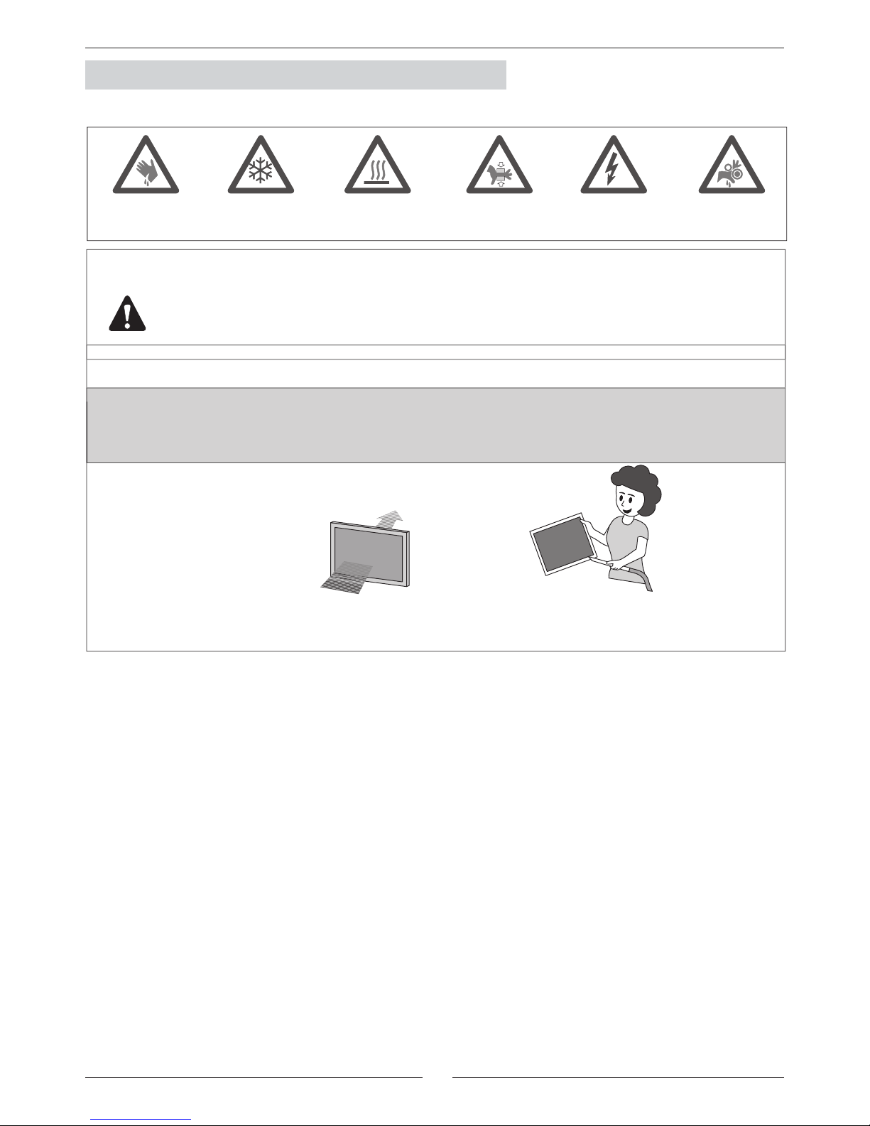
DANGER AND WARNING SIGNS
Abrasive surfaces
Low temperatures High temperatures Risk of injury from
moving objects
Electrical voltage
Risk of injury from
rotating objects
ELECTRICAL CONNECTIONS
To prevent serious electrical injuries, make sure to switch off the power before doing any installation,
repair or maintenance work on the unit.
To install the unit, bear in mind local and national legislation.
ATTENTION - WARNING
Electric shock can cause injury or death. Before attempting
to perform any service or maintenance on the unit, turn
OFF the electrical power, and check that the fan has
stopped.
The air fi lter cleaning operations does not require technical
service; however, when an electrical or mechanical
operation is required, call an Engineer.
CLEANING THE FILTER
Check the air fi lter and make sure
it is not blocked with dust or dirt.
If the fi lter is dirty, wash it in a bowl with neutral soap and
water, drying it in the shade before re-inserting it in the
unit.
Standard Guidelines for Lennox equipment.
All technical data contained in these operating instructions, including diagrams and technical descriptions, remain the property
of Lennox and may not be used (except for the purpose of familiarizing the user with the equipment), reproduced, photocopied,
transferred or transmitted to third parties without prior written authorization from Lennox.
Data published in the operating instructions are based on the latest information available. We reserve the right to make
modifi cations without notice.
We reserve the right to modify our products without notice and with no obligation to modify goods previously supplied.
These operating instructions contain useful and important information for the smooth operation and maintenance of your equipment.
The instructions also include guidelines on how to avoid accidents and serious damage before commissioning the equipment and
during its operation and how to ensure smooth and fault-free operation. Read the operating instructions carefully before starting
the equipment, familiarize yourself with the equipment and with handling the installation and carefully follow the instructions. It is
very important to be properly trained in handling the equipment. These operating instructions must be kept in a safe place near
the equipment.
Like most equipment, the unit requires regular maintenance. This section concerns maintenance personnel and management.
If you have any queries or would like to receive further information on any aspect relating to your equipment, do not hesitate to
contact us.
The manufacturing of these units is made under the requirements of the ISO 9001 and ISO 14001.
3
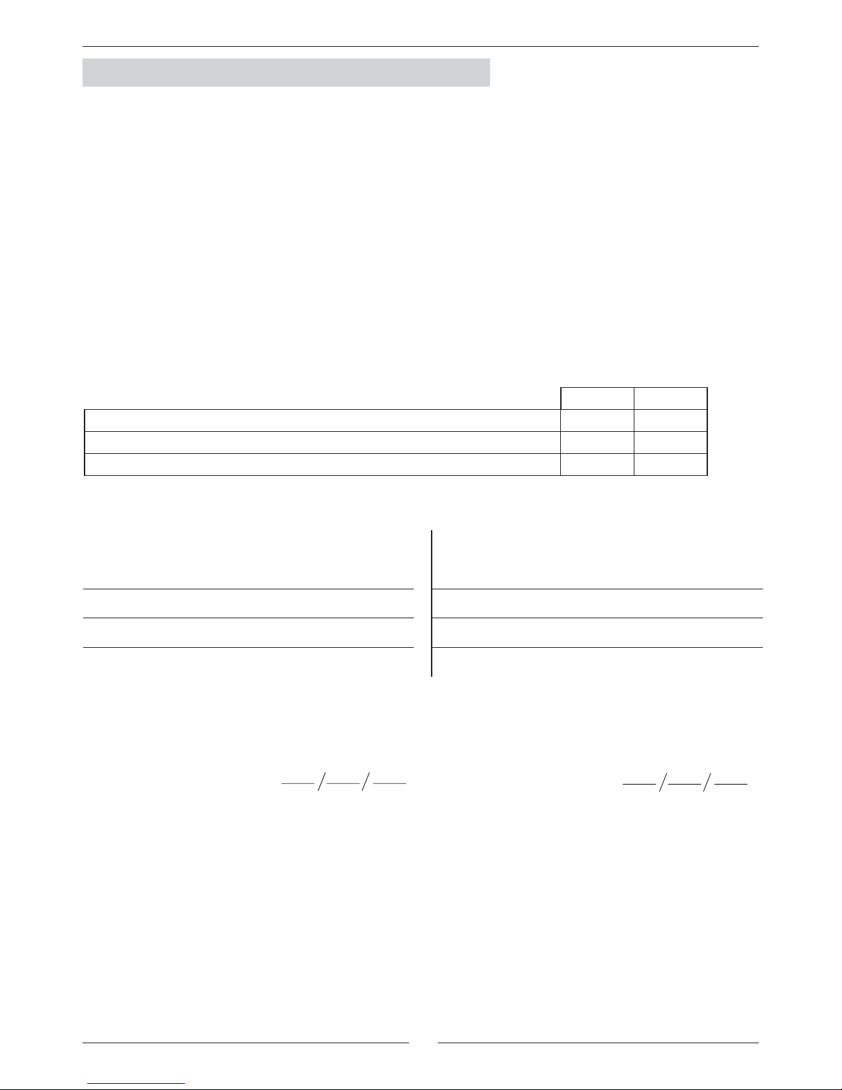
DATA PAGE FOR UNIT COMMISSIONING
COOLING CYCLE
Air fl ow data:
Air intake temperature, Indoor Coil:
ºC
High Pressure:
Low pressure :
HEATING CYCLE
Air fl ow data:
Air intake temperature, Indoor Coil:
ºC
High Pressure:
Low pressure :
YES NO
DRAINAGE WITH TRAP
CLEAN INTERIOR AIR FILTER
GENERAL POWER SUPPLY CONNECTION
DATA INPUT:
ELECTRIC POWER CONSUMPTION (Amps)
Fan indoor section: Fan indoor section:
UNIT: ______________________________________ SERIAL NUMBER : _____________________________
CONTROL PANEL IDENTIFICATION CODE : ______________________________________________________
INSTALLATION ADDRESS: ____________________________________________________________________
INSTALLER : ________________________________ INSTALLER TEL : ______________________________
INSTALLER ADDRESS : _______________________________________________________________________
___________________________________________________________________________________________
COMMISSIONING DATE : _____________________________________________________________________
CHECKS : __________________________________________________________________________________
___________________________________________________________________________________________
SUPPLY VOLTAGE : __________________________ RATED VOLTAGE OF THE UNIT : _________________
Options installed : ____________________________________________________________________________
___________________________________________________________________________________________
___________________________________________________________________________________________
___________________________________________________________________________________________
Comments : _________________________________________________________________________________
___________________________________________________________________________________________
___________________________________________________________________________________________
___________________________________________________________________________________________
___________________________________________________________________________________________
4
C I C 020 S
N
M
3
M
CIC
CIH
020S 025S 030S 035S 040S 045D 055D 070D 085D 100D 120D 140D
108 111 115 150 160 170 242 259 276 470 480 490
2 2 2 2 2 2 2 3 3 3 3 3
10 10 10 10 10 20 20 20 30 45 45 45
50 50 50 75 75 75 165 165 165 190 190 190
10 10 10 12 16 20 20 24 30 40 40 40
6,5 3 3 5 0 3 3 3 13 13 8 8
6,5 3 8 8 3 6 6 16 21 27 14 14
9,5 8 11 8 6 6 19 24 21 27 40 40
25 25 25 28 28 28 37 37 37 65 65 65
n/a n/a n/a n/a n/a n/a 145 145 145 230 230 230
6 6 6 9 9 9 14 14 14 23
23 23
CIC
CIH
020S 025S 030S 035S 040S 045D 055D 070D 085D 100D 120D 140D
0,74 1,45 1,45 1,89 2,69 2,69 2,69 3,63 5,06 5,06 6,38 6,38
1,40 2,59 2,59 3,45 4,80 4,80 4,80 6,48 8,60 8,60 11,1 11,1
6,44 13,0 13,0 17,3 26,4 26,4 26,4 35,6 60,2 60,2 81 81
3N
~400V
50 Hz
3~400V 50Hz
M:400V/3/50
- - - -
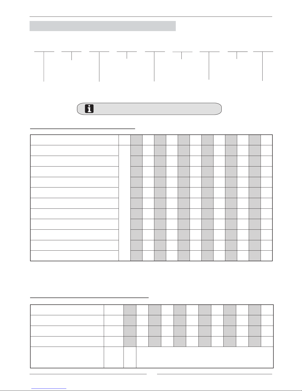
1. GENERAL CHARACTERISTICS
1.1.- PHYSICAL DATA
Type of unit
COMPACTAIR /
AIRCOOLAIR
I: Indoor unit
Type of Refrigerant
M: R-410A
Approximate cooling
capacity in kW.
S: One circuit
D: Two circuits
CIC: Cooling only unit R-410A.
CIH: Heat pump unit R-410A.
1.2.- ELECTRICAL DATA
ELECTRICAL CONSUMPTION FOR STANDARD UNITS
WEIGHT FOR STANDARD UNITS AND OPTIONS
C: Cooling only unit
H: Heat pump unit
Number of revision
MODELS
Indoor unit CIC/CIH
Airsock control
Electrical heater
Free-cooling
Hot water coil kg
Ventilation kit - HP1
Ventilation kit - HP2
Ventilation kit - HP3
Exhaust fan
Return fan
High effi ciency air fi lter
(G4 prefi ltre/F7 fi ltration)
MODELS
Maximum absorbed power
Kw
Maximum current
A
Start up current
A
Voltage
Ph/V/Hz
n/a: not available
5
CIC/H 020S CIC/H 025S CIC/H 030S CIC/H 035S
MAP MC MAP MC MAP MC MAP MC
0 0 0 0 0 0 0 0
0,71 1,19 0,44 0,86 0,44 0,86 0,8 1,35
0,71 1,19 1,24 2,21 1,24 2,21 1,74 3,03
1,15 2,05 1,24 2,21 2,18 3,89 1,74 3,03
0,51 2,6 0,51 2,6 0,51 2,6 1,33 6,8
n/a n/a n/a n/a n/a n/a n/a n/a
10 14,3 10 14,3 10 14,3 15 21,5
15 21,5 15 21,5 15 21,5 20 28,6
20 28,6 20 28,6 20 28,6 27 39
CIC/H 040S CIC/H 045D CIC/H 055D CIC/H 070D
MAP MC MAP MC MAP MC MAP MC
0 0 0 0 0 0 0 0
0 0 0,94 1,68 0,94 1,68 1,43 2,12
0,94 1,68 2,37 3,8 2,37 3,8 2,75 4,62
2,37 3,8 2,37 3,8 3,69 3,69 5,16 8,82
1,33 6,8 1,33 6,8 2,65 4,5 2,65 4,5
n/a n/a n/a n/a 2,69 4,8 3,63 6,5
15 21,5 15 21,5 20 28,6 20 28,6
20 28,6 20 28,6 27 39 27 39
27 39 27 39 40 57,8 40 57,8
CIC/H 085D CIC/H 100D CIC/CIH 120D/140D
MAP MC MAP MC MAP MC
0 0 0 0 0 0
1,32 2,5 1,32 2,5 2,41 4,2
3,73 6,7 5,06 8,6 3,74 6,1
3,73 6,7 5,06 8,6 6,38 11,1
2,65 4,5 5,3 9 5,3 9
3,63 6,5 5,06 8,6 6,38 11,1
20 28,6 27 39 27 39
27 39 40 57,8 40 57,8
40 57,8 50 72,3 50 72,3
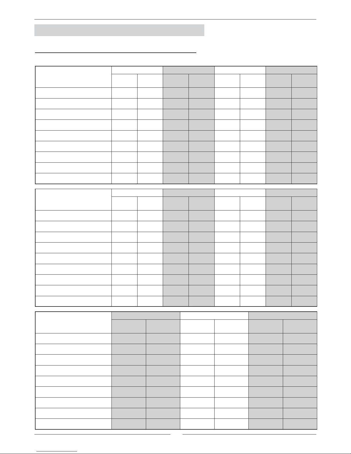
1. GENERAL CHARACTERISTICS
1.2.- ELECTRICAL DATA
ADDITIONAL ELECTRICAL CONSUMPTION FOR THE OPTIONS
kW A kW A kW A kW A
Standard Indoor fan
Ventilation kit - HP1
Ventilation kit - HP2
Ventilation kit - HP3
Exhaust fan
Return fan
Standard electrical heater
Medium electrical heater
High electrical heater
kW A kW A kW A kW A
Standard Indoor fan
Ventilation kit - HP1
Ventilation kit - HP2
Ventilation kit - HP3
Exhaust fan
Return fan
Standard electrical heater
Medium electrical heater
High electrical heater
kW A kW A kW A
Standard Indoor fan
Ventilation kit - HP1
Ventilation kit - HP2
Ventilation kit - HP3
Exhaust fan
Return fan
Standard electrical heater
Medium electrical heater
High electrical heater
MAP Maximum absorbed power MC Maximum current
6
020S
824 788 753 717 682
3150 167 149 132 116 101
3425 162 143
127
109 93
3700 155 138 120 103 85
4100 • 127
108
90 72
025S
824 788 753 717 682
4250 141 123 103 84 66
4625 129 109
89
69 49
5000 115 92 71 50 28
5500 89 66
42
19 n/a
030S
915 876 836 797 757
4650 173 149 125 103 80
5050 158 133
109
84 60
5450 141 115 89 63 38
6000 • 84
56
28 0
035S
735 704 672 640 609
6200 164 142 119 98 77
6650 153 130
106
83 61
7100 139 114 89 66 42
8050 102 75
48
22 n/a
040S
837 792 748 704 659
6950 213 178 143 109 75
7550 196 158
122
86 50
8150 175 136 97 58 21
9050 136 94
53
10 n/a
045D
937 888 838 788 738
6950 272 227 183 140 97
7550 249 201
155
109 63
8150 • 171 121 72 23
9050 • •
103
51 1
055D
837 792 748 704 659
9950 206 177 148 122 96
10825 195 166
138
110 83
11700 185 154 125 97 68
12850
136
105
75 45
070D
937 888 838 788 738
12450 237 200 163 128 95
13550
•
183
145
109 73
14650
• •
124 85 48
15090
• •
115
75 36
085D
937 888 838 788 738
14000 202 163 125 87 51
15125 182 142
102
62 23
16250 160 117 75 34 n/a
16725 149 105
63
20 n/a
100D
750 710 670 630 591
17350 237 202 167 133 101
18875 223 185
149
115 81
20400
•
168 131 94 59
22450
• •
100
63 25
120D
750 710 670 630 591
19300
207 169 133 98 64
21000
187 48
111
73 38
22700
164 124 84 46 9
24950
•
87
46
5 n/a
140D
750 710 670 630 591
21000
231 192 155 117 82
22250
218 178
140
101 65
23500
204 163 123 84 46
24750
•
146
105
65 25
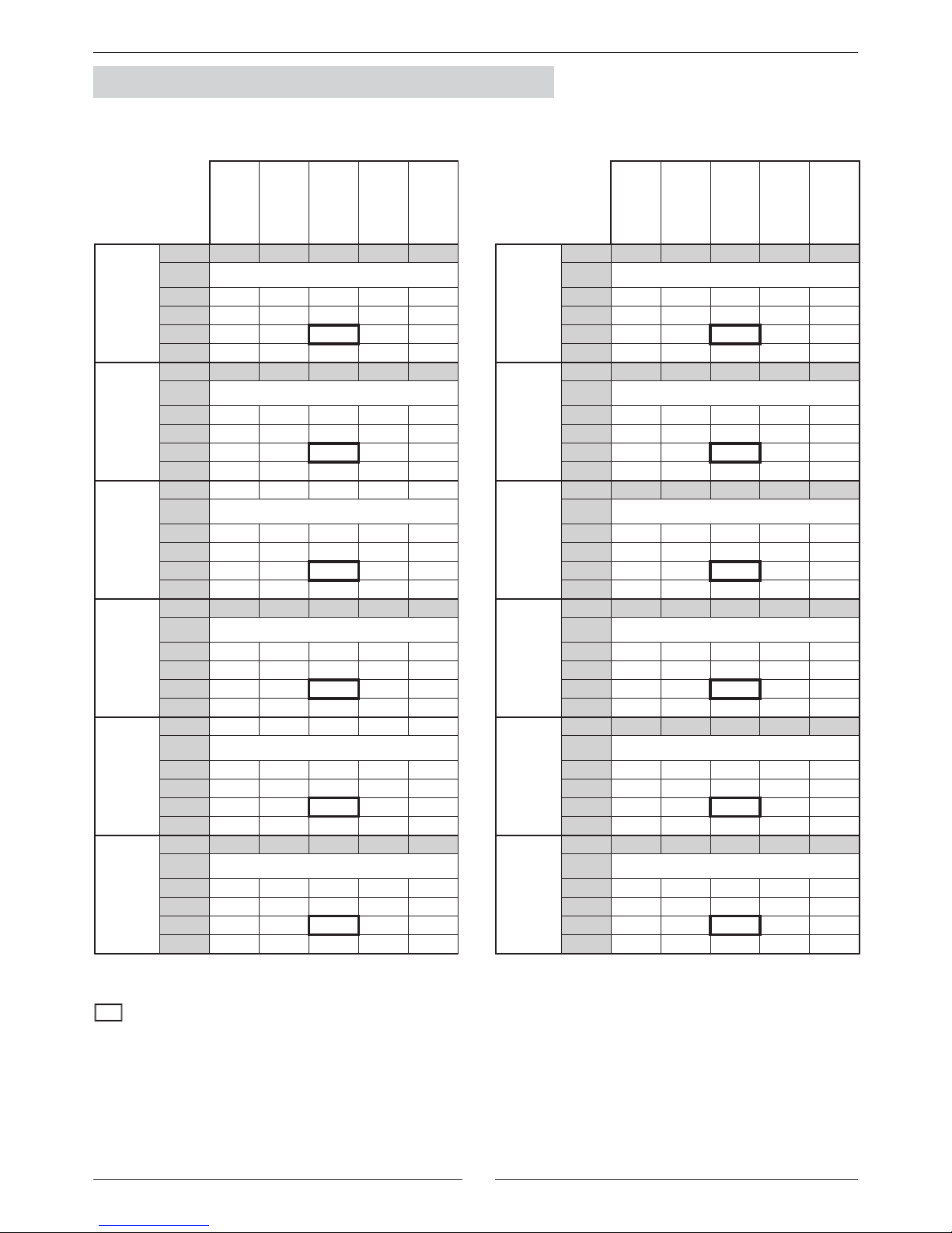
1.3.- FAN PERFORMANCES
1.3.1.- STANDARD FAN PERFORMANCES
CLOSED PULLEY
1 TURN
2 TURNS
3 TURNS
4 TURNS
rpm
m
3
/h
Available static pressure (Pa)
rpm
m
3
/h
Available static pressure (Pa)
rpm
m
3
/h
Available static pressure (Pa)
rpm
m
3
/h
Available static pressure (Pa)
rpm
m
3
/h
Available static pressure (Pa)
rpm
m
3
/h
Available static pressure (Pa)
CLOSED PULLEY
1 TURN
2 TURNS
3 TURNS
4 TURNS
rpm
m
3
/h
Available static pressure (Pa)
rpm
m
3
/h
Available static pressure (Pa)
rpm
m
3
/h
Available static pressure (Pa)
rpm
m
3
/h
Available static pressure (Pa)
rpm
m
3
/h
Available static pressure (Pa)
rpm
m
3
/h
Available static pressure (Pa)
(●) WRONG STATUS ON ACCOUNT OF MOTOR POWER LIMIT.
NOTE: With long distance kit option, the unit should not operate below its nominal airfl ow.
NOMINAL FACTORY SETTING.
1. GENERAL CHARACTERISTICS

7
020S
1098 1051 1003 956 909
3150 324 294 264 237 211
3425 321 289
261
233 207
3700 317 285 257 229 202
4100 310 279
249
222 193
025S
1098 1051 1003 956 909
4250 308 276 246 218 190
4625 301 269
239
209 180
5000 292 260 228 197 167
5500 278 244
211
178 146
030S
1098 1051 1003 956 909
4650 290 259 228 198 169
5050 280 248
215
184 154
5450 269 235 201 169 138
6000 249 213
178
143 109
035S
937 888 838 788 738
6200 321 281 241 203 167
6650 313 272
232
193 155
7100 306 262 221 181 142
8050 282 236
191
148 105
040S
937 888 838 788 738
6950 298 255 214 174 135
7550 283 240
197
155 113
8150 267 221 176 132 88
9050
•
186
138
90 43
045D
1041 986 931 876 820
6950 371 318 267 217 168
7550 353 298
244
190 139
8150 330 271 215 158 103
9050 316 258
199
141 84
055D
1041 986 931 876 820
9950 357 313 272 232 194
10825 349 304
263
223 185
11700
•
295 253 213 173
12850
• •
239
196 156
070D
1041 986 931 876 820
12450 321 276 232 191 151
13550 307 262
217
174 133
14650 291 244 199 154 110
15090
•
236
190
145 101
085D
1041 986 931 876 820
14000 288 242 197 155 112
15125 272 223
177
132 88
16250 253 203 154 107 60
16725 244 193
144
95 48
100D
837 792 748 704 659
17350 323 279 236 196 157
18875 310 264
221
180 140
20400 296 248 204 162 121
22450
• •
178
133 90
120D
837 792 748 704 659
19300 295 249 206 163 123
21000 278 231
186
142 101
22700 258 209 163 118 74
24950 228 176
127
80
35
140D
837 792 748 704 659
21000 322 275 230 186 145
22250 311 262
216
172 128
23500 299 249 202 157 112
24750 286 234
186
139
94
CLOSED PULLEY
1 TURN
2 TURNS
3 TURNS
4 TURNS
rpm
m
3
/h
Available static pressure (Pa)
rpm
m
3
/h
Available static pressure (Pa)
rpm
m
3
/h
Available static pressure (Pa)
rpm
m
3
/h
Available static pressure (Pa)
rpm
m
3
/h
Available static pressure (Pa)
rpm
m
3
/h
Available static pressure (Pa)
CLOSED PULLEY
1 TURN
2 TURNS
3 TURNS
4 TURNS
rpm
m
3
/h
Available static pressure (Pa)
rpm
m
3
/h
Available static pressure (Pa)
rpm
m
3
/h
Available static pressure (Pa)
rpm
m
3
/h
Available static pressure (Pa)
rpm
m
3
/h
Available static pressure (Pa)
rpm
m
3
/h
Available static pressure (Pa)
(●) WRONG STATUS ON ACCOUNT OF MOTOR POWER LIMIT.
NOTE: With long distance kit option, the unit should not operate below its nominal airfl ow.
NOMINAL FACTORY SETTING.
1. GENERAL CHARACTERISTICS
1.3.2.- FAN PERFORMANCES WITH KIT HIGH STATIC PRESSURE (OPTIONAL TRANSMISSION)
VENTILATION HP1
 Loading...