

Page 1
INSTALLATION AND OPERATION MANUAL
US
Free-Standing
EPA Certied
Wood-Burning Stoves
Retain These Instructions
For Future Reference
P/N 775,080M, Rev. G, 09/2007
A French manual is available upon request. Order P/N 775,080CF.
Ce manuel d’installation est disponible en francais, simplement en faire la demande. Numéro de la
pièce 775,080CF.
CI1000HT Report #132-S-03-2
CI2000HT Report #132-S-05-2.
Model CI2000HT Shown
Spectra™ Series Wood Stoves
Models CI1000HT and CI2000HT
These appliances must be properly installed and operated in order to prevent the
possibility of a house re. Please read this entire installation and operation
manual before installing and using your wood stove. Failure to follow
these instructions could result in property damage, bodily injury or
even death. Contact your local building or re ofcials to obtain
a permit and information on any installation requirements
and inspection requirements in your area.
WARNINGS
• Hot! Do not touch! The glass and surfaces of this appliance will
be hot during operation and will retain heat for a while after
shutting off the appliance. Severe burns may result.
• Carefully supervise children in the same room as appliance.
Page 2
IMPORTANT SAFETY AND WARNIING
INFORMATION
READ THIS MANUAL IN ITS ENTIRETY AND UNDERSTAND THESE RULES TO FOLLOW FOR SAFETY
CAUTION
Read this manual thoroughly before starting installation. For your safety, follow the installation,
operation and maintenance instructions exactly
without deviation. Failure to follow these instructions may result in a possible fire hazard and will
void the warranty. If this appliance is not properly
installed, a house fire may result. Contact local
building or fire officials about requirements and
installation inspection in your area.
WARNING
Improper installation, adjustment, alteration, service or maintenance can cause injury or property
damage. Refer to this manual. For assistance or
additional information consult a qualified installer,
service agency or the gas supplier.
WARNING
Do not attempt to alter or modify the construction of
the appliance or its components. Any modification
or alteration may void the warranty, certification
and listings of this unit.
1. If utilizing an older chimney, it must be inspected for adequate
serviceability. Refer to the heading Chimney Inspection on
Page 10 of this manual.
2. The minimum clearances must be maintained for all combustible surfaces. The following materials should be kept a
minimum of 36 inches (914 mm) from the heater; furniture,
carpet, drapes, clothing, wood, papers, etc. Do not store
firewood within this clearance space. Failure to maintain
clearances to all combustibles may result in a house fire.
3. This appliance requires floor protection as out-lined in this
manual (see Floor Protection on Pages 4 through 8).
4. WARNING: improper installation, adjustment, alteration,
service or maintenance can cause injury or property damage.
This appliance must be properly installed or the listing will be
void. Installations other than those specifically covered herein
have not been confirmed by test and are not covered by the
listing.
5. Minimum ceiling height must be 5 feet (measured from base
of appliance to ceiling).
6. DO NOT CONNECT THIS UNIT TO A CHIMNEY FLUE CONNECTED
TO ANOTHER APPLIANCE.
7. Do not connect this appliance to air ducts or any air distribution
system.
8. PREVENT CREOSOTE FIRE: Inspect and clean chimney connector and chimney daily for creosote build-up until experience
shows how often you need to clean to be safe
2
Under certain conditions of use, creosote buildup may occur
rapidly. Be aware that the hotter the fire the less creosote is
deposited, and weekly cleaning may be necessary in mild
weather even though monthly cleaning may be enough in
the coldest months. Using green or inadequately seasoned
.
wood can greatly increase creosote buildup. Use dry wood to
minimize creosote buildup.
9. USE SOLID WOOD FUEL ONLY: This appliance is approved
for burning dry seasoned natural wood only. CAUTION: BURN
UNTREATED WOOD ONLY. DO NOT BURN GARBAGE OR FLAMMABLE FLUIDS SUCH AS GASOLINE, NAPHTHA OR ENGINE
OIL.
10.Never use gasoline, gasoline-type lantern fuel, kerosene,
charcoal lighter fluid, or similar liquids to start or “freshen
up” a fire in this heater. Keep all such liquids well away from
the heater while it is in use.
11.DO NOT OVERFIRE: If heater or chimney connector glows, you
are overfiring. Overfiring this appliance could cause a house
fire. Overfiring is a condition where the appliance is operated
at tem-peratures above its design capabilities. Overfiring can
be caused by improper installation, improper operation, lack
of maintenance or improper fuel usage. Do not operate the
stove with the doors open or ajar, as this will produce extreme
temperatures within the stove. Damage caused from overfiring
is NOT covered under the manufacturers limited warranty (see
Care and Operation section on Pages 14 through 18).
12.NEVER LEAVE AN UNATTENDED STOVE BURNING ON HIGH.
Operation of the stove with the primary air draft control at
its highest burn rate setting for extended periods can cause
dangerous overfiring conditions. The primary air draft control should only be positioned at the highest setting during
start-up procedures (see How to Start and Maintain a Fire
on Page 15) and for short durations. When leaving the stove
unattended ensure that the primary air draft control is set to
the low or medium low range.
13.It is imperative that the control compartments and circulating
air passageways of the appliance be kept clean.
14.Use a metal container with a tight fitting lid to dispose of
ashes.
15.IN THE EVENT OF A COMPONENT FAILURE, USE ONLY COMPONENTS PROVIDED BY THE MANUFACTURER AS REPLACEMENT PARTS.
16.Burning any kind of fuel uses oxygen from the dwelling. Be
sure that you allow an adequate source of fresh air into the
room where the stove is operating (see Ventilation Require-
ments on Page 12).
17.CAUTION: HOT WHILE IN OPERATION. An appliance hot
enough to warm your home can severely burn anyone touching
it. Keep children, clothing and furniture away. Contact may
cause skin burns. Do not let children touch the appliance.
Train them to stay a safe distance from the unit. The use of
a fireguard is recommended.
18.Do not operate this appliance without the firebox baffle brick
properly installed.
19.Always build wood fires directly on the firebox grate. Do not
use andirons or any other method to elevate the fire.
20.Do not install these appliances into a Manufactured (Mobile)
Home.
21.See the listing label located on the back of stove (or see
Safety/Listing Labels on Pages 32 & 33).
22.These appliances are designed as supplemental heaters.
Therefore, it is advisable to have an alternate heat source
when installed in a dwelling.
23.SAVE THESE INSTRUCTIONS. Ensure that this manual
remains with the appliance and passed to the user after
installation.
Page 3

CONGRATULATIONS!
PACKAGING LIST
When you purchased your new wood stove, you joined the ranks of
thousands of concerned individuals whose answer to their home
heating needs reflects their concern for aesthetics, efficiency and our
environment. We extend our continued support to help you achieve
the maximum benefit and enjoyment available from your new wood
stove.
It is our goal at Lennox to provide you, our valued customer, with
an appliance that will ensure you years of trouble free warmth and
pleasure.
Thank you for selecting a Lennox stove as the answer to your home
heating needs.
Sincerely,
All of us at Lennox Hearth Products
TABLE OF CONTENTS
Important Warnings Page 2
Testing/Listing, EPA Page 3
Packaging List Page 3
Using this Manual Page 3
Planning Your Installation Page 3
Clearances - CI1000HT Page 8
Clearances - CI2000HT Page 9
Installation Page 10
Care and Operation Page 14
Recommended Fuel / Wood Storage Page 18
Maintenance Page 19
Troubleshooting Page 21
Specifications - CI1000HT Page 22
Specifications - CI2000HT Page 23
Replacement Parts List Page 24
Optional Accessories Page 31
Safety/Listing Label - CI1000HT Page 32
Safety/Listing Label - CI2000HT Page 33
EPA Labels Page 34
Service and Maintenance Log Page 35
Product Reference Information Page 36
This installation and operation manual will help you obtain a safe, efficient, dependable installation for your appliance and vent system.
The assembled wood stove models CI1000HT and CI2000HT are packaged
with an accessory package which contains the following:
One - Installation and Operation Manual
One - Warranty Certificate
One - Wood and Brass, Removable Door Handle (for opening the ashpan
One - Air Control / Ash Pan Removal Tool
One - Fire Poker
Four - Leg Cushions
One - Spray Can of Charcoal Paint
door, firebox door and side door)
USING THIS MANUAL
Please read and carefully follow all of the instructions found in this manual.
Please pay special attention to the safety instructions provided in this
manual. The homeowner’s care and operation Instructions included here
will assure you have many years of dependable and enjoyable service
from your appliance.
PRODUCT IS SUBJECT TO CHANGE WITHOUT NOTICE
PLANNING YOUR INSTALLATION
Questions To Ask Local Building Official
A correct installation is critical and imperative for reducing fire hazards
and perilous conditions that can arise when wood burning appliances are
improperly installed. The installer must follow all of the manufacturers’
instructions. These models are designed as radiant room heaters and
should be used for no other purpose.
The installation of a wood burning appliance must conform to local codes
and applicable state and federal requirements and a building permit must
be obtained before installing. Familiarity with these requirements before
installation is essential. Important considerations to discuss with local
building officials include:
1.
Applicable codes (i.e. Uniform Mechanical Code, State or Regional
Codes.)?
2. Local amendments?
3. Is a permit required - cost?
(You may wish to contact your insurance company to ask if they require
this?).
4. Rooms where the installation is not allowed?
Smoke Detectors
PLEASE READ AND UNDERSTAND THESE INSTRUCTIONS
BEFORE BEGINNING YOUR INSTALLATION
TESTING / LISTING
Models CI1000HT and CI2000HT have been Listed to UL Standard #1482
and ULC-S627 by OMNI-Test Laboratories, Inc.; Beaverton, OR; Report
numbers; CI1000HT #132-S-03-2 and CI2000HT #132-S-05-2.
EPA (Environmental Protection Agency)
This heater meets EPA particulate matter (smoke) control requirements
for noncatalytic wood heaters built on or after July 1, 1990.
Since there are always several potential sources of fire in any home, we
recommend installing smoke detectors. If possible, install the smoke
detector in a hallway adjacent to the room (to reduce the possibility of
occasional false activation from the heat produced by these appliances).
If your local code requires a smoke detector be installed within the same
room, you must follow the requirements of your local code. Check with
your local building department for requirements in your area.
Installation / Solid Fuel Standards
National Fire Protection Association – The primary NFPA standard that
refers to installation and maintenance of wood fired appliances and
venting is NFPA 211 – Latest Edition: Chimneys, Fireplaces, Vents, and
Solid Fuel appliances.
Note – This appliance is NOT approved for installation into a Manu
factured Home.
-
3
Page 4
SELECTING A LOCATION
The design of your home and where you place your stove will determine
its value as a source of heat. This type of appliance depends primarily on
air circulation (convection) to disperse its heat, and therefore, a central
location is often best. There are other practical considerations, which must
be considered before a final selection of locations is made.
• Existing Chimneys
CAUTION
The body of these appliances are very heavy. The
use of a heavy duty escalara (stair step hand truck)
is recommended for lifting the appliance body.
Floor Protection - Model CI1000HT
(USA ONLY)
• Wood Storage
• Aesthetic Considerations
• Roof Design (rafter locations & roof pitch)
• Room Traffic
• Proximity to Combustibles
The installation of these appliances will require some research. Once your
options are determined, consult with your local building department who
will be able to give you the necessary installation requirements for your
area (Is a building permit required? Rooms where installation may not
be allowed, etc.).
WARNING
Check all local building and safety codes before
installation. The installation instructions and appropriate code requirements must be followed exactly
and without compromise. Alterations to the stove are
not allowed. Do not connect the stove to a chimney
system serving another stove, appliance, or any air
distribution duct. Failure to follow these instructions
will void the manufacturers warranty.
The floor protector must meet or exceed the minimum thermal requirements as defined here (see Floor Protection / Hearth Extension Using
Alternate Material As Floor Protector). If the floor protection is to be
stone, tile, brick, etc., it must be mortared or grouted to form a continuous noncombustible surface. If a chimney connector extends horizontally
over the floor, protection must also cover the floor under the connector
and at least 2” (51 mm) to either side.
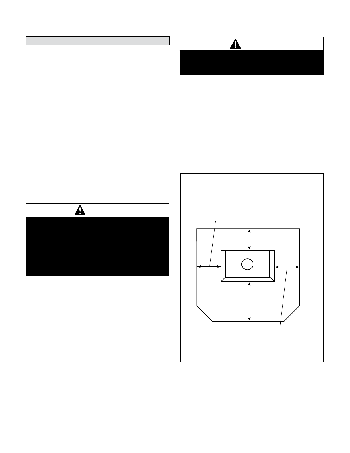
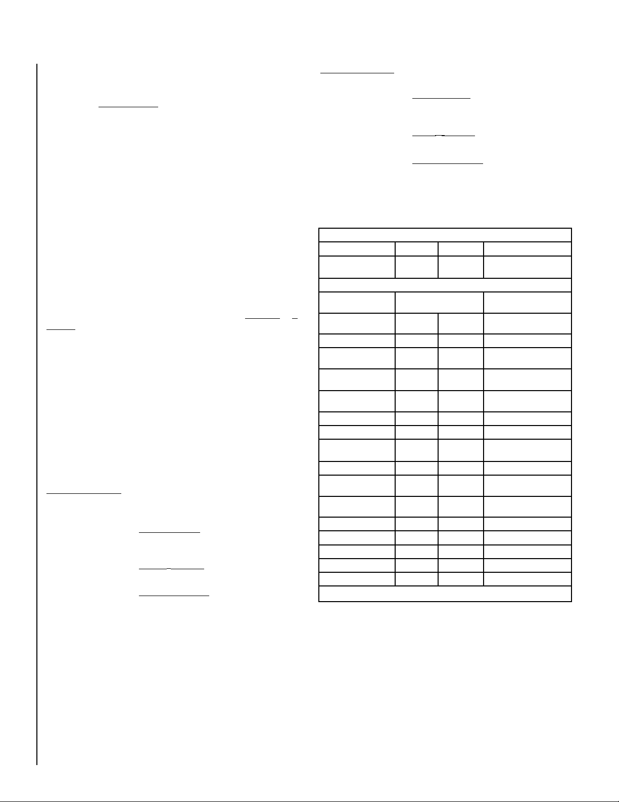
The floor protector must fully cover the area beneath the appliance and
extend 18” to the front, 5.2” to the sides, and 0” from the back as shown
in Figure 1.
For Floor Protection Material Requirements:
In USA see Page 5
In Canada see Page 6
USA - 5.2” (132 mm)
Canada - 8” (203 mm)
Minimum
Floor
Protector
USA - 0 “ (0 mm)
Canada - 8” (203 mm)
Minimum
Stove Back
Stove Front
If you plan to vent your stove into an existing masonry chimney, have it
inspected by a local fire marshal or qualified installer. Remember that a
stove’s performance is heavily influenced by the chimney and its location
on the roof. An oversized flue may not provide effective draw, and a flue
liner may be required (see Draft Requirements on Page 11). Consult your
dealer or qualified installer before final selection is made.
This stove requires pre-installation work to be completed before installation
can take place. This may include modification for flue and chimney.
The appliance should be inspected before use and the chimney cleaned
at least annually. More frequent cleaning may be required due to poor
operation, installation, or low quality fuel.
4
NOTE: DIAGRAMS & ILLUSTRATIONS ARE NOT TO SCALE
USA - 5.2” (132 mm)
Canada - 18” (457 mm)
Minimum
Top View
USA - 5.2” (132 mm)
Canada - 8” (203 mm)
Minimum
Figure 1 - Floor Protection Requirements, Model CI1000HT
Page 5
Floor Protection / Hearth Extension Using Alternate Material As
Floor Protector - Model CI1000HT (USA only)
Note: Also see Floor Protection above .
The hearth pad or alternate material used as a floor/hearth protector must
be constructed of a durable noncombustible material having an equal or
better thermal conductivity value (lower k value) of k =.84 BTU/IN FT2
HR °F or a thermal resistance that equals or exceeds r = 1.19 HR °F FT2
IN/BTU with a minimum thickness of 1/2”. With these values, determine
the minimum thickness of the alternate material required using the
formula(s) and shown in Table 1.
Note:
Any noncombustible material having a minimum thickness of 1/2”
(13 mm) whose k value is less than .84 or whose r value is more than
1.19 is acceptable. If the alternate material used has a higher k value
or lower r value will require a greater thickness of the material used. In
some cases, if the k value is less or the r value higher, a thinner material
may be used.
Methods of determining floor protection equivalents:
To determine the thickness required for the alternate material when
either the "k" value or "r" value is known, use either the k formula or r
formula.
Example: If Durock™ Cement Board is to be used for the floor protection,
how thick must this material be?
kM = k value per inch of alternate material
rM = r value per inch of alternate material
TM = minimum thickness required for alternate material
TS = standard thickness of the alternate material
kL = k value per inch of listed material
rL = r value per inch of listed material
TL = minimum thickness of listed material
Note: An asterisk "*" indicates, it is a value taken from Table 1.
Using the k formula:
Minimum k-value (per Inch) of Specified min.
thickness of =
alternate material (kM) x thickness
alternate k-value (per inch) of listed
material (TM) of listed material (kL) material (TL)
TM (inches) = kM x TL
*.84
TM (inches) = *1.92 x .5"
*.84
1.143 (inches)= 2.286 x
Answer - The minimum required thickness of the Durock is 1.143" therefore
round up to nearest standard thickness available which is 1-1/4."
.5"
Using the r formula:
Minimum r-value (per Inch) Specified min.
thickness of =
of listed material x thickness
alternate r-value (per inch) of listed
material of alternate material material
TM (inches) =
r
L x T
rM
L
TM (inches) = *1.19 x .5"
* .52
1.144 (inches)= 2.288 x
Answer - The minimum required thickness of the Durock is 1.143" therefore
round up to nearest standard thickness available which is 1-1/4."
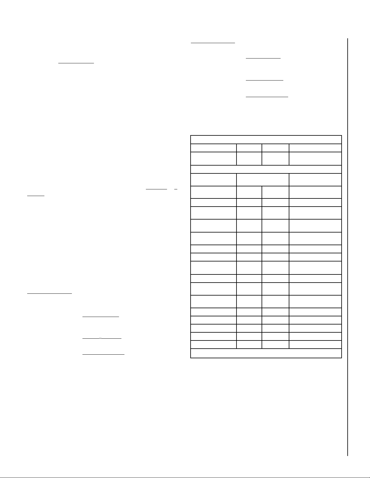
Listed Material
k (per inch) r (per inch) Listed Min. Thickness
Listed Material .84
** Approved Alternate Materials for Floor/Hearth Protection
Alternative Materials Thermal Values Minimum Thickness
Kaowool M Board .47 2.13 .28" (1/4")
Micore 160™
U.S. Gypsum
Micore 300™
U.S. Gypsum
Durock™ Cement Board
U.S. Gypsum
Hardibacker™ 1.95 .51 1.16" (1-1/8")
Hardibacker 500™ 2.30 .43 1.37" (1-3/8")
Cultured Stone Hearthstone™
Wonderboard 3.23 .31 1.92" (1-7/8")
Super Firetemp M
Johns-Manville
Super Firetemp L
Johns-Manville
Face brick 9.00 .111 5.36" (5-3/8")
Common brick 5.00 .20 2.98" (3")
Cement mortar 5.00 .20 2.98" (3")
Ceramic tile 12.5 .08 7.44" (7-1/2")
Marble ~11 ~.09 6.55" (6-1/2")
K
L
k (per inch)
K
M
.35 2.86 .21" (1/4")
.46 2.17 .27" (1/4")
1.92 .52 1.14" (1-1/8")
2.82 .35 1.68" (1-5/8")
.61 1.64 .36" (3/8")
.54 1.85 .32" (3/8")
1.19
r
L
r (per inch)
r
M
.5"
1/2" (.5")
T
L
(rounded to nearest 1/8 inch)
Min. Thickness
T
M
Table 1
** If the hearth extension material(s) that is intended to be used is NOT listed
on Table 1, the material can still be used if the material(s) is noncombustible.
However, the manufacturer of the material must provide either the listed k-value
per inch or r-value per inch with listed thickness so that the minimum thickness
required for the hearth can be calculated (per instructions on this Page and/or
as specified in the NFI Certification Manuals).
Note: Also see NFI (National Fireplace Institute) Certification Manuals show
ing other acceptable calculation methods and acceptable alternate materials
which can be used.
-
NOTE: DIAGRAMS & ILLUSTRATIONS ARE NOT TO SCALE
5
5
Page 6
Floor Protection / Hearth Extension Using Alternate Material As
Floor Protector - Model CI1000HT (Canada only)
Note: Also see Floor Protection above .
The hearth pad or alternate material used as a floor/hearth protector must
be constructed of a durable noncombustible material having an equal or
better thermal conductivity value (lower k value) of k =.84 BTU/IN FT2
HR °F or a thermal resistance that equals or exceeds r = 1.19 HR °F FT2
IN/BTU with a minimum thickness of 1/2”. With these values, determine
the minimum thickness of the alternate material required using the
formula(s) and shown in Table 2.
Note:
Any noncombustible material having a minimum thickness of 1/2”
(13 mm) whose k value is less than .84 or whose r value is more than
1.19 is acceptable. If the alternate material used has a higher k value
or lower r value will require a greater thickness of the material used. In
some cases, if the k value is less or the r value higher, a thinner material
may be used.
Methods of determining floor protection equivalents:
To determine the thickness required for the alternate material when
either the "k" value or "r" value is known, use either the k formula or r
formula.
Example: If Durock™ Cement Board is to be used for the floor protection,
how thick must this material be?
kM = k value per inch of alternate material
rM = r value per inch of alternate material
TM = minimum thickness required for alternate material
TS = standard thickness of the alternate material
kL = k value per inch of listed material
rL = r value per inch of listed material
TL = minimum thickness of listed material
Note: An asterisk "*" indicates, it is a value taken from Table 2.
Using the k formula:
Minimum k-value (per Inch) of Specified min.
thickness of =
alternate material (kM) x thickness
alternate k-value (per inch) of listed
material (TM) of listed material (kL) material (TL)
TM (inches) = kM x TL
*.84
TM (inches) = *1.92 x 1.45"
*.84
1.143 (inches)= 2.286 x 1
Answer - The minimum required thickness of the Durock is 3.31" therefore
round up to nearest standard thickness available which is 3-5/16."
.45"
Using the r formula:
Minimum r-value (per Inch) Specified min.
thickness of =
of listed material x thickness
alternate r-value (per inch) of listed
material of alternate material material
TM (inches) =
r
L x T
rM
L
TM (inches) = *1.19 x 1.45"
* .52
1.144 (inches)= 2.288 x 1
Answer - The minimum required thickness of the Durock is 3.31" therefore
round up to nearest standard thickness available which is 3-5/16."
Listed Material
k (per inch) r (per inch) Listed Min. Thickness
Listed Material .84
** Approved Alternate Materials for Floor/Hearth Protection
Alternative Materials Thermal Values Minimum Thickness
Kaowool M Board .47 2.13 .81" (3/4")
Micore 160™
U.S. Gypsum
Micore 300™
U.S. Gypsum
Durock™ Cement Board
U.S. Gypsum
Hardibacker™ 1.95 .51 3.37" (3-3/8")
Hardibacker 500™ 2.30 .43 3.97" (4")
Cultured Stone Hearthstone™
Wonderboard 3.23 .31 5.58" (5-5/8")
Super Firetemp M
Johns-Manville
Super Firetemp L
Johns-Manville
Face brick 9.00 .11 15.54" (15-1/2")
Common brick 5.00 .20 8.63" (8-5/8")
Cement mortar 5.00 .20 8.63" (8-5/8")
Ceramic tile 12.5 .08 21.58" (21-5/8")
Marble ~11 ~.09 18.99" (19")
K
L
k (per inch)
K
M
.35 2.86 .60" (5/8")
.46 2.17 .79" (3/4")
1.92 .52 3.31" (3-3/8")
2.82 .35 4.87" (4-7/8")
.61 1.64 1.05" (1")
.54 1.85 .93" (7/8")
1.19
r
L
r (per inch)
r
M
(rounded to nearest 1/8 inch)
.45"
1.45" (1-1/2")
T
L
Min. Thickness
T
M
Table 2
** If the hearth extension material(s) that is intended to be used is NOT listed
on Table 2, the material can still be used if the material(s) is noncombustible.
However, the manufacturer of the material must provide either the listed k-value
per inch or r-value per inch with listed thickness so that the minimum thickness
required for the hearth can be calculated (per instructions on this Page and/or
as specified in the NFI Certification Manuals).
Note: Also see NFI (National Fireplace Institute) Certification Manuals show
ing other acceptable calculation methods and acceptable alternate materials
which can be used.
-
6
NOTE: DIAGRAMS & ILLUSTRATIONS ARE NOT TO SCALE
Page 7
Floor Protection - Model CI2000HT (USA and Canada)
The floor protector must meet or exceed the minimum thermal requirements as defined on this Page (see Floor Protection / Hearth Extension
Using Alternate Material As Floor Protector). If the floor protection is
to be stone, tile, brick, etc., it must be mortared or grouted to form a
continuous noncombustible surface. If a chimney connector extends
horizontally over the floor, protection must also cover the floor under
the connector and at least 2” (51 mm) to either side.
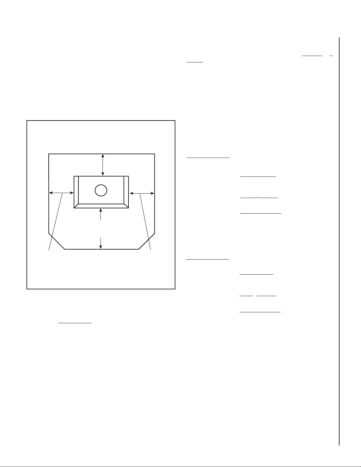
The floor protector must fully cover the area beneath the appliance and
extend 18” to the front, 5”-USA and 8”-Canada to the sides, and 0”-USA
and 8”-Canada from the back as shown in Figure 2.
Methods of determining floor protection equivalents:
To determine the thickness required for the alternate material when
either the "k" value or "r" value is known, use either the k formula or r
formula.
Example: If Durock™ Cement Board is to be used for the floor protection,
how thick must this material be?
kM = k value per inch of alternate material
rM = r value per inch of alternate material
TM = minimum thickness required for alternate material
TS = standard thickness of the alternate material
Note: For Floor Protection Material Requirements in USA and Canada
see Floor Protection Using Alternate Material As Floor Protector on
this page.
Floor
Protector
USA - 18” (457 mm)
Canada - 18” (457 mm)
USA - 5” (127 mm)
Canada - 8” (203 mm)
Minimum
USA - 0 “ (0 mm)
Canada - 8” (203 mm)
Minimum
Stove Back
Stove Front
Minimum
USA - 5” (127 mm)
Canada - 8” (203 mm)
Minimum
Top View
Figure 2- Floor Protection Size Requirements, Model CI2000HT
Floor Protection / Hearth Extension Using Alternate Material As
Floor Protector - Model CI2000HT (USA and Canada)
Note: Also see Floor Protection above .
The hearth pad or alternate material used as a floor/hearth protector must
be constructed of a durable noncombustible material having an equal or
better thermal conductivity value (lower k value) of k =.84 BTU/IN FT2
HR °F or a thermal resistance that equals or exceeds r = 1.19 HR °F FT2
IN/BTU with a minimum thickness of 1/2”. With these values, determine
the minimum thickness of the alternate material required using the
formula(s) and shown in Table 3.
kL = k value per inch of listed material
rL = r value per inch of listed material
TL = minimum thickness of listed material
Note: An asterisk "*" indicates, it is a value taken from Table 3.
Using the k formula:
Minimum k-value (per Inch) of Specified min.
thickness of =
alternate material (kM) x thickness
alternate k-value (per inch) of listed
material (TM) of listed material (kL) material (TL)
TM (inches) = kM x TL
*.84
TM (inches) = *1.92 x .5"
*.84
1.143 (inches)= 2.286 x
Answer - The minimum required thickness of the Durock is 1.143" therefore
round up to nearest standard thickness available which is 1-1/4."
.5"
Using the r formula:
Minimum r-value (per Inch) Specified min.
thickness of =
of listed material x thickness
alternate r-value (per inch) of listed
material of alternate material material
TM (inches) =
r
L x T
rM
L
TM (inches) = *1.19 x .5"
* .52
1.144 (inches)= 2.288 x
Answer - The minimum required thickness of the Durock is 1.143" therefore
round up to nearest standard thickness available which is 1-1/4."
.5"
Note:
Any noncombustible material having a minimum thickness of 1/2”
(13 mm) whose k value is less than .84 or whose r value is more than
1.19 is acceptable. If the alternate material used has a higher k value
or lower r value will require a greater thickness of the material used. In
some cases, if the k value is less or the r value higher, a thinner material
may be used.
NOTE: DIAGRAMS & ILLUSTRATIONS ARE NOT TO SCALE
7
Page 8
Floor Protection - Model CI2000HT (USA and Canada)
Continued...
CLEARANCES - MODEL CI1000HT
Listed Material
k (per inch) r (per inch) Listed Min. Thickness
Listed Material .84
** Approved Alternate Materials for Floor/Hearth Protection
Alternative Materials Thermal Values Minimum Thickness
Kaowool M Board .47 2.13 .28" (1/4")
Micore 160™
U.S. Gypsum
Micore 300™
U.S. Gypsum
Durock™ Cement Board
U.S. Gypsum
Hardibacker™ 1.95 .51 1.16" (1-1/8")
Hardibacker 500™ 2.30 .43 1.37" (1-3/8")
Cultured Stone Hearthstone™
Wonderboard 3.23 .31 1.92" (1-7/8")
Super Firetemp M
Johns-Manville
Super Firetemp L
Johns-Manville
Face brick 9.00 .111 5.36" (5-3/8")
Common brick 5.00 .20 2.98" (3")
Cement mortar 5.00 .20 2.98" (3")
Ceramic tile 12.5 .08 7.44" (7-1/2")
Marble ~11 ~.09 6.55" (6-1/2")
K
L
k (per inch)
K
M
.35 2.86 .21" (1/4")
.46 2.17 .27" (1/4")
1.92 .52 1.14" (1-1/8")
2.82 .35 1.68" (1-5/8")
.61 1.64 .36" (3/8")
.54 1.85 .32" (3/8")
1.19
r
L
r (per inch)
r
M
1/2" (.5")
T
L
(rounded to nearest 1/8 inch)
Min. Thickness
T
M
Table 3
** If the hearth extension material(s) that is intended to be used is
NOT listed on Table 3, the material can still be used if the material(s)
is noncombustible. However, the manufacturer of the material must
provide either the listed k-value per inch or r-value per inch with listed
thickness so that the minimum thickness required for the hearth can
be calculated (per instructions on this Page and/or as specified in the
NFI Certification Manuals).
Note: Also see NFI (National Fireplace Institute) Certification Manuals
showing other acceptable calculation methods and acceptable alternate
materials which can be used.
COMBUSTIBLE WALL CLEARANCE – USA & Canada
WARNING: It is very important that you observe the minimum
clearances.
There are listed clearances for your stove which were determined in a
Laboratory test using various “classes” of stove pipe or chimney. Minimums are first established for the stove itself and increased based on
how much heat is transferred by each class of pipe.
Position the unit no closer than the minimum clearances to combustible
materials. Check that no overhead cross members in the ceiling or roof
will be cut. Reposition unit if necessary being careful not to move closer
than the minimum clearances.
Minimum Ceiling Height – 7 feet / 2133mm from floor to ceiling.
Single Wall Pipe Without Pipe Shield - CI1000HT
Using single wall 24 MSG black or 25 MSG blued steel connector pipe
with factory-built chimney listed to either UL 103HT or ULC S629.
Minimum Clearances to Combustibles - inches (millimeters)
A 27-1/2” (699 mm) D 24” (610 mm)
B 27” (686 mm) E 18” (457 mm)
C 27” (686 mm) F 19” (483 mm)
G 35-3/16” (894 mm) This is a reference dimension only
Table 4 - Model CI1000HT (see Figures 3 and 4)
Single Wall Pipe With Pipe Shield / Reduced Clearance CI1000HT
Using single wall 24 MSG black or 25 MSG blued steel connector pipe
with factory-built chimney listed to either UL 103HT or ULC S629. The
use of a pipe shield for 6” connector with 1” clearance to the pipe is
mandatory.
Minimum Clearances to Combustibles - inches (millimeters)
A 21-1/2” (546 mm) D 18” (457 mm)
B 27” (686 mm) E 18” (457 mm)
C 19” (483 mm) F 11” (279 mm)
G 23-7/8” (606 mm) This is a reference dimension only
Table 5 - Model CI1000HT (see Figures 3 and 4)
Protected Wall Clearance - CI1000HT and CI2000HT
Some local codes will allow reduced clearances when the stove is
installed adjacent to a protected wall system. The variance must be
approved by your local building official. Normally, the protected wall
system is defined as a non- combustible material with a minimum of
1” air space behind. Check your local building codes or with a qualified
installer (Ref. NFPA 211).
8
NOTE: DIAGRAMS & ILLUSTRATIONS ARE NOT TO SCALE
Page 9
CLEARANCES - MODEL CI2000HT
COMBUSTIBLE WALL CLEARANCE – USA & Canada
Combustible
WARNING: It is very important that you observe the minimum
clearances.
There are listed clearances for your stove which were determined in a
Laboratory test using various “classes” of stove pipe or chimney. Minimums are first established for the stove itself and increased based on
how much heat is transferred by each class of pipe.
Position the unit no closer than the minimum clearances to combustible
materials. Check that no overhead cross members in the ceiling or roof
will be cut. Reposition unit if necessary being careful not to move closer
than the minimum clearances.
Single Wall Pipe - CI2000HT
(Not approved for alcove installations)
Using single wall 24 MSG black or 25 MSG blued steel connector pipe
with factory-built chimney listed to either UL 103HT or ULC S629.
Minimum Clearances to Combustibles - inches (millimeters)
A 18” (457 mm) D 13” (330 mm)
B 32” (813 mm) E 20” (508 mm)
C 27” (686 mm) F 16” (406 mm)
G 35-3/16” (894 mm) This is a reference dimension only
Table 6 (see Figures 3 and 4)
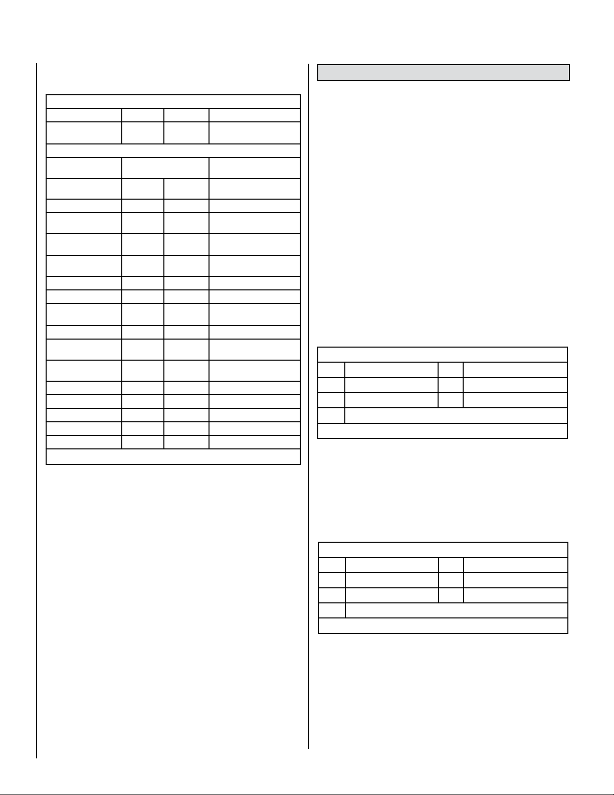
Double Wall Pipe - CI2000HT
D
E
Combustible
B
Figure 3 - Parallel Installation
Combustible
G
Combustible
B
A
F
C
(For alcove installations, clearances “C” and “F” are not applicable) Use
listed double wall chimney connector or Type L vent pipe to the top of
the stove.
Minimum Clearances to Combustibles - inches (millimeters)
A 14-1/2” (368 mm) D 10” (254 mm)
B 28-1/2” (724 mm) E 17” (432 mm)
C 18” (457 mm) F 7” (178 mm)
Table 7 (see Figures 3 and 4)
Minimum Ceiling Height for Single wall pipe and double wall pipe installations and Alcove Installations – 60” (1524 mm) from floor to ceiling
and 29” (737 mm) from stove top to ceiling.
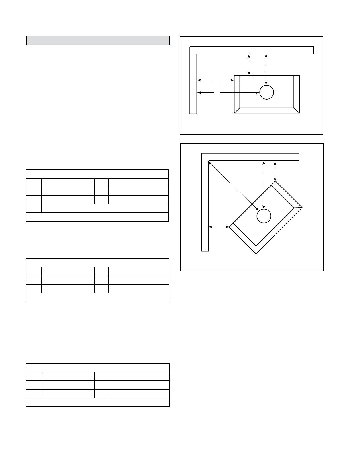
Alcove Installation Clearances - CI2000HT
Alcove Installations Require Double Wall Pipe Only
Use listed double wall chimney connector or Type L vent pipe to the top
of the stove.
Minimum Clearances to Combustibles - inches (millimeters)
A 14-1/2” (368 mm) D 10” (254 mm)
B 28-1/2” (724 mm) E 17” (432 mm)
C N/A F N/A
Table 8 (see Figures 3 and 4)
Figure 4 - Corner Installation
MODEL CI1000HT IS NOT APPROVED FOR USE WITH DOUBLE
WALL PIPE.
DO NOT INSTALL THE CI1000HT INTO AN ALCOVE OR A CONFINED
SPACE. This unit has not been tested or approved for installation
into a confined space such as an alcove (see the national standard
below).
NFPA 211- latest edition: (Applies to Solid Fuel Burning Appliances,
which are not alcove tested) - Solid fuel-burning appliances shall
not be installed in confined spaces. The space or room shall be of
ample size to allow adequate circulation of heated air. Appliances
shall be so located as not to interfere with the proper circulation
of air within the heated space.
Installing Leg Pads
The four leg pads (included in accessory package), are provided for
placement under the four legs.
Note:
Alcove clearances cannot be reduced using wall protection. Maxi-
mum alcove depth must be no more than 48” (1220 mm).
NOTE: DIAGRAMS & ILLUSTRATIONS ARE NOT TO SCALE
9
Page 10

INSTALLATION
Minimum / Maximum Flue Diameter:
Minimum 6”, Maximum 10”
Types of Chimneys
The unit must be connected to either a code-approved masonry chimney
with a flue liner, or a 6 inch diameter factory-built chimney complying with
the requirements for Type HT chimneys in the standard UL 103.
The chimney is a vital part of your stove installation. A properly built
masonry chimney or a properly installed factory-built chimney will assure
a consistent draft under a variety of weather conditions (a smoking
stove is usually caused by a chimney problem). The stove flue size is
6 inches diameter, which is approximately 28 square inches minimum.
The maximum flue size should be no more than three (3) times the cross
sectional area of the size of the stove flue collar. In this case, that would
be no larger than an 10-inch diameter stack, or approximately 85 square
inches maximum.
All chimneys must be installed as specified by local building codes and
according to the chimney manufacturer instructions (in the case of
a factory-built chimney). See the chimney manufacturer instructions
for exact specifications. Factory-built chimneys must comply with UL
103HT or ULC S629. A chimney connector shall not pass through an attic
or roof space, closet or similar concealed space, or a floor, or ceiling.
Where passage through a wall, or partition of combustible construction
is desired, the installation shall conform to CAN/CSA-B365, Installation
Code for Solid-Fuel-Burning Appliances and Equipment.
Tile-lined Masonry Chimney
Chimney Connector Adapter
Use a chimney connector adapter to connect the chimney connector up
to the chimney. The small ends of the chimney connector should all point
down for a drip free installation. Position all seams toward the back for
aesthetics. The chimney connector must be 6-inch diameter.
Secure adjoining sections of chimney connector to each other using three
equally spaced sheet metal screws. Secure the connector pipe to flue
collar using three equally spaced sheet metal screws. DO NOT secure
chimney connector to chimney with screws.
Connection To A Factory-built Chimney
This space heater is to be connected to a factory-built chimney conforming
to CAN / ULC – S629, Standard for 650°C Factory-Built Chimneys. All pipe
connections must be sealed (ie. high temperature silicone).
For Reduced Residential Clearances Using Double Wall Pipe (Approved
for Model CI2000HT Only):
Type L and listed double wall connector pipe is acceptable. Install any factory-built brand of pipe according to the manufacturer’s instructions.
Vapor Barrier at Chimney Penetration
Install all venting components per the Vent Manufacturers installation
instructions. Ensure that there is an effective vapor barrier at the location
where the chimney penetrates to the exterior of the structure. This can
be accomplished by applying a non-hardening waterproof sealant to the
following components:
Factory
Built
Figure 5 - Types of Chimney
Chimney
Acceptable Connector Pipe For Installations
When Using Single Wall Pipe: Install a six (6) inch diameter, single wall,
24 MSG black steel or 26 MSG blued steel connector pipe on the flue
collar of the unit. When installing pipe, the crimped ends of the pipe
should all point down. Position all seams toward the back for aesthetics. Three (3) pre-drilled holes are provided in the flue collar for fastening the pipe securely to the stove. Use sheet metal screws to do this.
Additional sections of single wall pipe should be fastened together with
at least three (3) sheet metal screws each section. All pipe connections
must be sealed (ie. high temperature silicone). When connecting to the
factory-built ceiling support package, use the manufacturer’s transition
piece, usually called a dripless connector, to join single wall pipe to their
factory-built chimney section.
When Using Approved Double Wall Pipe (Approved for Model CI2000HT
Only)
Type L and listed double wall connector pipe is acceptable. Install any
factory-built brand of pipe according to the manufacturer’s instructions.
All pipe connections must be sealed (ie. high temperature silicone).
• Around the chimney at the point where the storm collar will meet the
chimney just above the Flashing
• Along the vertical seam of the chimney pipe, where it is exposed to
the weather.
• On each nail head on the flashing.
• Around the chimney at the point where the storm collar will meet the
chimney just above the flashing.
Notes:
• On a flat or tarred and graveled roofs, nail and seal the flat roof flashing
to the roof on all sides with roofing compound.
• Do not put screws through the flashing into the chimney pipe.
Chimney Inspection
Existing chimneys must be inspected before installing your stove. Consult your local building department for chimney code requirements. A
masonry chimney must have a code approved liner. This liner must not
have broken or missing pieces. Some non-code masonry chimneys may
be brought up to code by being relined. (Consult your dealer or qualified
chimney sweep). Factory-built chimneys should also be inspected, first
for creosote deposits (which should be removed), and then for integrity
of the stainless steel liner. Look for obvious bulges in the lining, which
may indicate the need to replace that section (use a bright flashlight).
Also, inspect the attic to see that the chimney has proper clearance to
combustible framing members. For interior masonry chimneys and most
factory-built chimneys, this must be a two (2) inch air space clearance,
which must not be filled with insulation or any other material. An exterior
masonry chimney must have a one (1) inch air space clearance.
10
NOTE: DIAGRAMS & ILLUSTRATIONS ARE NOT TO SCALE
Page 11
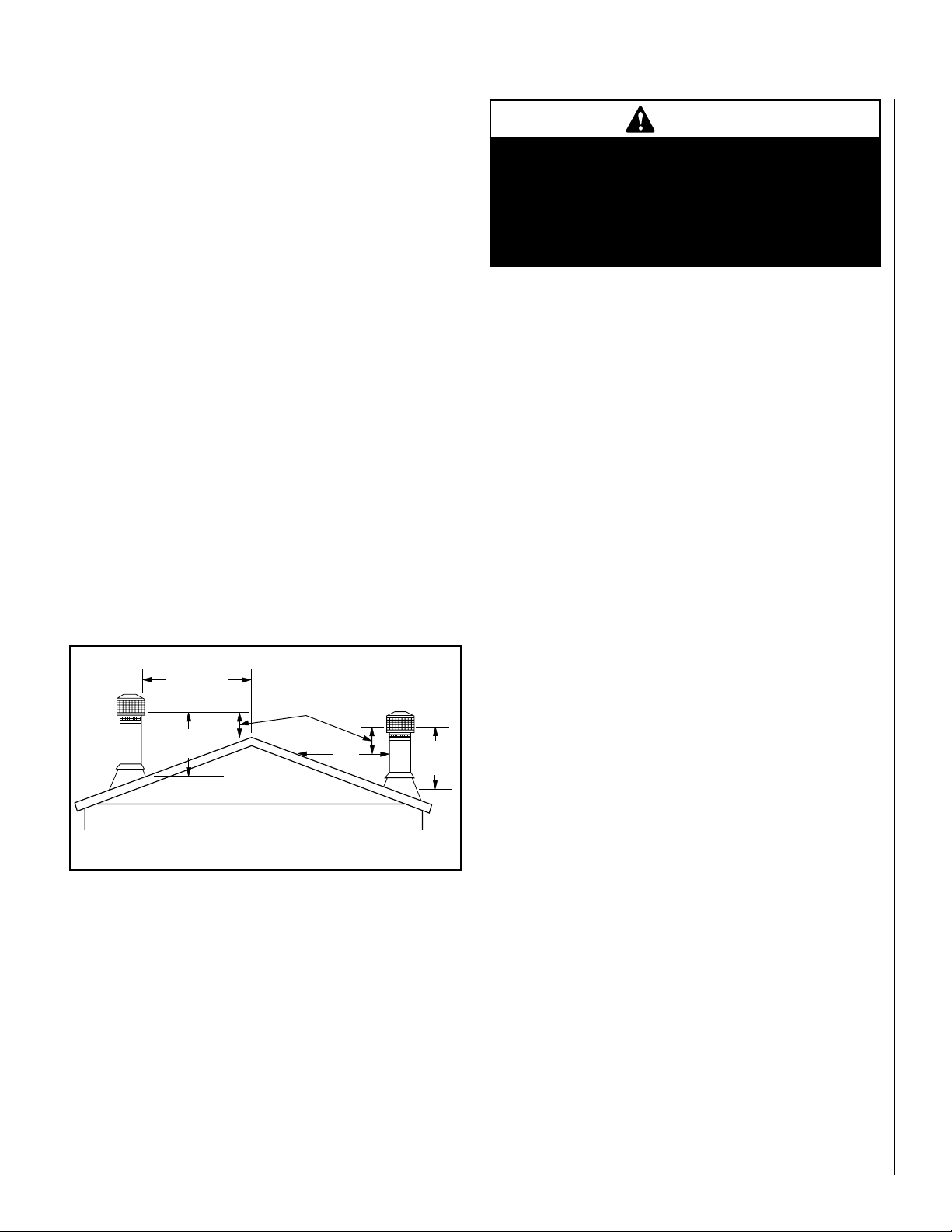
Chimney Height Requirements
Less than
10' (3 m)
10'
(3 m)
3' (914 mm)
Min.
2’ (610 mm) Min.
(914 mm)
Min.
3'
The chimney must extend 3 feet above the level of roof penetration and a
minimum of 2 feet higher than any roof surface within 10 feet (see below).
Check with your local building officials for any additional requirements
for your area.
Due to prevailing winds, local terrain, adjacent tall trees, a hill, or ravine
near the home, or adjacent structures, additional chimney height or a
special chimney cap may be required to ensure optimum performance.
See Figure 6 for the 10’ by 2’ Rule for Vent Termination. The top of the
flue must be 2’ (610 mm) higher than any part of the roof within 10’ (305
cm) horizontal and a minimum of 3’ (915 mm) higher than the highest
point of roof penetration.
Important Note:
The installation of a barometric damper is recommended for all freestanding stoves in areas that may have high winds, which can effect the
draft. The installation must be only in units with a newly constructed
chimney, free of creosote deposits. The barometric damper is an automatic device designed to regulate the draft in a heating appliance, which
in turn, stabilizes the chimney temperatures, lessening the potential of
over-firing. Do not place the barometric damper greater than 24 inches
(610 mm) above the unit. Excessive draft will lead to poor control of
the burning rate and possible over-firing of the stove and damage to the
cast iron firebox. Most barometric dampers are calibrated in inches of
water column and can be set to draft requirements of -.03 to -.08 inches
(-7.5 to -20 Pa). It is recommended that the barometric dampers to be
set between -.05 and -.06 inches.
CAUTION
Many structure fires have resulted when a slow burning
fire has been left unattended for any extended period
of time. These fires normally occur because combustible materials close to an appliance become heated
to the ignition point by an overfired appliance which
the operator thought was safety “throttled down.”
Draft Requirements
The appliance is merely one component of a larger system. The other
equally important component is the venting system which is necessary
for achieving the required flow of combustion air to the fire chamber and
for safely removing unwanted combustion by-products from the appliance. If the venting system’s design does not promote these ends, the
system may not function properly. Poorly functioning venting systems
may create performance problems (i.e. smoking stove, poor heat output,
fire goes out, window blackens, increased creosote buildup, etc.) as
well as be a safety hazard. Some factors that may lead to performance
problems are as follows:
• Oversized or undersized chimney.
• Excessive offsets in venting.
• Insufficient vertical height of chimney.
• Insufficient chimney termination height in relationship to roof.
• Insufficient ventilation.
• Lack of maintenance.
• Improper operation.
• Burning improper fuel (unit is approved for use with natural dry wellseasoned wood only).
• Down drafts in the chimney (may need a special wind cap).
Figure 6 - The 10’ by 2’ Rule for Vent Termination
THE RECOMMENDED DRAFT REQUIREMENTS FOR THESE APPLIANCES
IS NO LESS THAN -.05 AND NO GREATER THAN -.06. OPERATION OF
YOUR STOVE WITH A DRAFT GREATER THAN -.06 CAN POSSIBLY CAUSE
DAMAGE TO THE STOVE AND VOID THE WARRANTY.
Fire intensity is a function of several factors. One of these factors is DRAFT.
Normally, increasing draft increases fire intensity. Conversely, increasing
the fire intensity will increase draft. Draft can also be affected by external
factors such as wind strength and direction, outside temperature, airflow
in or out of the structure, and so forth. If one of these factors changes,
the draft of a low-burning appliance may increase. This increased draft
may cause dangerously high temperature to develop, possibly causing
failure of the unit or flue, or ignition of nearby combustibles. Closing
down the combustion airflow (“Primary Air Draft Control”) may not
guarantee that this will not happen.
NOTE: DIAGRAMS & ILLUSTRATIONS ARE NOT TO SCALE
To ensure that the venting system is functioning properly a draft test
should be performed (see Draft Test Procedure on this page).
American National Standards Institute ANSI/NFPA 211-96: A chimney or
vent shall be so designed and constructed to develop a flow sufficient
to completely remove all flue and vent gases to the outside atmosphere.
The venting system shall satisfy the draft requirements of the connected
appliance in accordance with the manufacturer instructions.
Draft Test Procedure
After this appliance is installed a draft test should be performed to
ensure proper draft. A qualified technician should perform the draft test
procedure as follows:
1) Close all windows and doors in the dwelling.
2) Turn on or operate all appliances which remove air from the home
(such as a furnace, heat pump, air conditioner, clothes dryer, exhaust
fans, fireplaces, and other fuel burning appliances).
11
Page 12

3) Drill a hole in the vent pipe per the draft gauge manufacturers instruc-
tions (to create a draft test port). Note: Hole location should be a
minimum of 1 foot above flue outlet collar.
4) Start a fire (See How To Start And Maintain A Fire on Page 15).
5) After the fire is well established (20-25 minutes) and burning at a low
setting, perform the draft test per the gauge manufacturer instructions.
The draft gauge should read between .05 and .06” W.C. (inches water
column). Excessive draft (above .06 W.C.I.) can result in too much
combustion air to be pulled into the firebox, this will produce hotter
burns and could result in overfiring. Too little draft (below .05” W.C.)
will not allow enough combustion air delivery to maintain a fire well
or cause performance problems such as smoking (this may result in
improper operation of appliance, i.e. will not maintain fire well unless
fuel door is left open).
6) Install a screw to seal the draft test port in the vent pipe. If the draft
test reading was not within the required range, correct the installation
and repeat this procedure.
Single Wall Pipe
Using 6” Diameter Single Wall Connector Pipe
Chimney
Termination
Cap
Storm
Collar
Roof
Flashing
Ceiling Support
Assembly
Ventilation Requirements / Provide Adequate Air For Combustion
THE FRESH AIR REQUIREMENTS OF THIS APPLIANCE MUST BE MET
WITHIN THE SPACE WHERE IT WILL BE INSTALLED. VENTILATION IS
ESSENTIAL WHEN USING A SOLID FUEL BURNING HEATER.
In well insulated and weather tight homes, it may be difficult to establish
a good draft up the chimney (caused by a shortage of air in the home).
The lack of air is caused by many common household appliances which
exhaust air from the home (such as a furnace, heat pump, air conditioner,
clothes dryer, exhaust fans, fireplaces, and other fuel burning appliances).
Also, the combustion process of this heater uses oxygen from inside the
dwelling. If the available fresh air delivery in the dwelling is insufficient
to support the demands of these appliances, problems can result (i.e.
excessive negative pressure can develop in the dwelling which will affect
the rate at which this appliance can draft thus resulting in performance
problems; See Draft Requirements on Page 11). To correct this problem
it may help to open a window (preferably on the windward side of the
house) or install a vent to provide make-up air into the dwelling.
Important Notes:
• Minimize the use of elbows (30°, 45° or 90°) - Offsets in the venting
system are very restrictive and will inhibit the draft (i.e. You will lose
approximately 5 feet of effective draft for every 90 degrees of direction
change). This appliance requires 12 to 15 feet of effective draft for
optimum performance (see Draft Requirements on Page 11).
Slip
Adapter
Chimney
Connector
6” x 24” 24-gage
black steel or 26 gage
blued steel single
wall pipe
• First section of pipe must be vertical - Use as much straight vertical
pipe directly above the appliance as possible before using an elbow
(a 2’ to 3’ initial vertical rise is suggested).
• See pipe manufacturers instructions for installation requirements of
venting components and vent clearances.
12
NOTE: DIAGRAMS & ILLUSTRATIONS ARE NOT TO SCALE
Figure 7 - Single Wall Pipe
Page 13

Double Wall Pipe
(Approved for Model CI2000HT Only)
Using 6” Diameter Type L-Vent Connector Pipe
Termination Cap with
Spark Arrestor
3 Feet
Minimum
Storm
Collar
Flashing
Support
Box
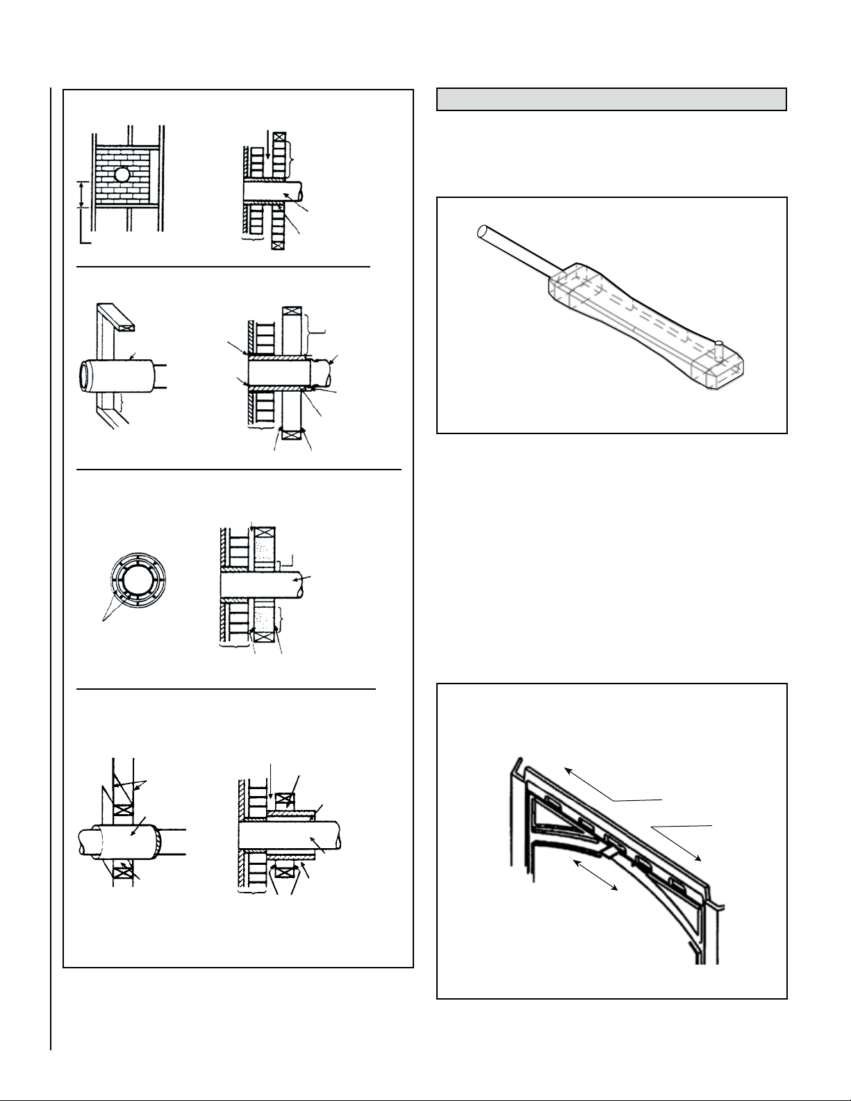
Combustible Wall Chimney Connector Pass-Throughs
Refer to Figure 9
Method A. 12” (305 mm) Clearance to Combustible Wall Member:
Using a minimum thickness 3.5” (89 mm) brick and a 5/8” (16 mm)
minimum wall thickness clay liner, construct a wall pass-through. The
clay liner must conform to ASTM C315 (Standard Specification for Clay
Fire Linings) or its equivalent. Keep a minimum of 12” (305 mm) of brick
masonry between the clay liner and wall combustibles. The clay liner
shall run from the brick masonry outer surface to the inner surface of
the chimney flue liner but not past the inner surface. Firmly grout or
cement the clay liner in place to the chimney flue liner.
Method B. 9” (229 mm) Clearance to Combustible Wall Member: Using
a 6” (153 mm) inside diameter, listed, factory-built Solid-Pak chimney
section with insulation of 1” (26 mm) or more, build a wall pass-through
with a minimum 9” (229 mm) air space between the outer wall of the
chimney length and wall combustibles. Use sheet metal supports
fastened securely to wall surfaces on all sides, to maintain the 9” (229
mm) air space. When fastening supports to chimney length, do not
penetrate the chimney liner (the inside wall of the Solid-Pak chimney).
The inner end of the Solid-Pak chimney section shall be flush with the
inside of the masonry chimney flue, and sealed with a non-water soluble
refractory cement. Use this cement to also seal to the brick masonry
penetration.
Minimum of
12-15’ of Flue to
achieve a stable
draft.
7 Feet
Minimum
Floor
Protector
Figure 8 - Double Wall Pipe
DVL Close Clearance
Connector Pipe
Method C. 6” (153 mm) Clearance to Combustible Wall Member:
Starting with a minimum 24 gage (.024” [.61 mm]) 6” (153 mm) metal
chimney connector, and a minimum 24 gage ventilated wall thimble which
has two air channels of 1” (26 mm) each, construct a wall pass-through.
There shall be a minimum 6” (153 mm) separation area containing
fiberglass insulation, from the outer surface of the wall thimble to wall
combustibles. Support the wall thimble, and cover its opening with a
24-gage minimum sheet metal support. Maintain the 6” (153 mm) space.
There should also be a support sized to fit and hold the metal chimney
connector. See that the supports are fastened securely to wall surfaces
on all sides. Make sure fasteners used to secure the metal chimney
connector do not penetrate chimney flue liner.
Method D. 2” (51 mm) Clearance to Combustible Wall Member: Start
with a solid-pak listed factory built chimney section at least 12” (304 mm)
long, with insulation of 1” (26 mm) or more, and an inside diameter of
8” (2 inches [51 mm] larger than the 6” [153 mm] chimney connector).
Use this as a pass-through for a minimum 24-gage single wall steel
chimney connector. Keep solid-pak section concentric with and spaced
1” (26 mm) off the chimney connector by way of sheet metal support
plates at both ends of chimney section. Cover opening with and support chimney section on both sides with 24 gage minimum sheet metal
supports. See that the supports are fastened securely to wall surfaces
on all sides. Make sure fasteners used to secure chimney section do
not penetrate chimney flue liner.
1. Connectors to a masonry chimney, excepting method B, shall extend
in one continuous section through the wall pass-through system and
the chimney wall, to but not past the inner flue liner face.
2. A chimney connector shall not pass through an attic or roof space,
closet or similar concealed space, or a floor, or ceiling.
3. Where passage through a wall, or partition of combustible construction is desired, the installation shall conform to CAN/CSA-B365.
NOTE: DIAGRAMS & ILLUSTRATIONS ARE NOT TO SCALE
13
Page 14
D
C
B
A
Min. 12 in. (304.8mm)
to Combustibles
Masonry
Chimney
Fire Clay
Liner
Chimney
Connector
Min. Clearance 12 in.
(304.8mm) of Brick
Minimum Chimney Clearance to Brick &
Combustibles – 2 in. (51mm)
Chimney Flue
Factory Built
Chimney Length
Air Space – 9 in.
(228.6mm) Min.
Chimney Length
Flush with
Inside of Flue
Min. Clearance
9 in. (228.6mm)
Chimney
Connector
Use Chimney
Mfrs. Parts to
Attach
Connector
Solid-Insulated
Listed FactoryBuilt Chimney
Length
Sheet Steel Su
pp
orts
yenmihC
eulF
Minimum Chimney Clearance from Masonry to Sheet Steel
Supports & Combustibles – 2 in. (51mm)
Nonsoluble
Refractory
Cement
Min. Chimney Clearance from Masonry to Sheet Steel
Supports & Combustibles – 2 in. (51mm)
Chimney
Connector
2 Air Channels, Each 1
in. (25.4 mm)
Min. 6 in.
(152.4mm) glass
Fiber Insulation
2 Ventilated Air
Channels, Each
1 in. (25.4 mm)
Construction of
Sheet Steel
Sheet Steel Su
pp
orts
Masonry
Chimney
e
u
lF
y
e
n
m
i
hC
Min. Chimney Clearance from
Masonry to Sheet Steel Supports
& Combustibles – 2 in. (51mm)
Sheet Steel
Supports
Chimney
Connector
Chimney
Section
Air Space – 2 in.
(51mm) Min.
Masonr
y
Chimney
Sheet
Steel
Supports
Chimney
Connector
Chimney
Length
1 in. (25.4 mm)
Air Space to
Chimney
Length
Min. Clearance
2 in. (51 mm)
CARE AND OPERATION
Primary Air Draft Control
Use the air control adjustment tool (provided - see FigrueX 10) to adjust
the air controls per the following instructions.
Figure 10 - Air Control / Ash Pan Removal Tool
The primary combustion air delivery is controlled by the Primary Air
Draft Control Assembly (located above the front door). The heat output
can be controlled by sliding the control to a higher or lower heat output
setting using the Air Control Tool Provided (See Primary Air Draft Control
below).
The fuel, the amount of heat and burn times desired, the type of installation are all variables that will affect the control setting. The same control
settings in a variety of installations will produce different results. You will
need to try different settings so you can learn how much heat to expect
and how long the fire will burn.
With the air control tool (provided in accessory package) the control can
be adjusted to the heat output desired (see Figure 11).
14
Figure 9 - Combustible Wall Chimney Connector Pass-Throughs
NOTE: DIAGRAMS & ILLUSTRATIONS ARE NOT TO SCALE
Primary Air Draft Control
Using the air control tool (provided) slide
the control above door to adjust burn rate.
Lower Burn / Slide Left
Higher Burn / Slide Right
Figure 11 - Primary Air Draft Control
Page 15

Adjusting Burn Rate:
How To Start And Maintain A Fire
The primary air draft control located above the front door can be adjusted to
the right for higher temperatures and to the left for lower temperatures.
Generally, you will want to set the draft control somewhere in the low
or medium range
Tips - Adjust the primary air control to a medium to low setting for a slow
and more efficient burn. When burning on a higher setting, it is more
efficient to burn with a bright but not roaring fire.
Start Up Air Control (Ignition Booster)
To facilitate lighting, your stove is equipped with an ignition booster,
which brings start-up air to the fire for a short period of time. This can
be especially helpful when your chimney is cold. The ignition booster can
also be used to allow the fire to recover quickly following refuelling.
IMPORTANT
The Start-Up Air Control provides supplemental
primary air. Do NOT leave the start-up air contol
in the open position for more than five minutes
(this could result in dangerous overfiring which is
not covered under the warranty). Close by pushing
the lever inwards.
1. Using the Air Control Tool (provided), open the Start-Up Air Control
(see Start-Up Air Control, on this Page).
2. Adjust the primary air draft control to the full open position (see
Primary Air Draft Control on Page 14).
3. Open the side fuel loading door and build your fire directly on the grate
in the firebox.
a. Place five or six loosely crumpled sheets of newspaper in the
stove.
b. Add a small amount of dry kindling randomly on the top of the
newspaper.
c. Place a few more loosely crumpled newspapers on top of the
kindling and light the bottom paper first, then light the top paper.
Once the fire is well underway, close the door. The upper fire
should preheat the chimney and create an effective draft while
the lower fire ignites the kindling.
4. After the kindling is burning well, add increasingly larger pieces of
wood until the fire is actively burning (see bullets below). Leave the
fuel door open (slightly ajar for 5 minutes). Then close the stove door.
Never leave the stove unattended when the door is open.
• When loading fuel, be careful not to smother the fire.
Stove Back
Slide to Open
Start-Up Air
Control Module
Figure 12 - Start-up Air Control
Before Initial Lighting
1. Using the air control tool open the start-up air control by pulling the
lever outwards (see Figure 12).
• Load logs evenly across the base being cautious not to place
wood in front of the rear edge of the log guard.
5. Once a bed of coals has been established, adjust the primary air control
to a lower setting AND CLOSE THE START-UP AIR CONTROL.
Air Delivery Systems
Tip – Using the air control tool, adjust the primary air draft control to
a medium to low setting for a slow and more efficient burn. On higher
settings, it is more efficient to burn with a bright but not roaring fire.
When Refueling
1. Follow the normal procedure for refuelling described on Page 17.
However, instead of cracking the door open 1/2," open the start-up
air control by pulling the lever outwards. This will supply enough
primary combustion air to allow the fire to recover.
2. Load fuel into the firebox and light the fire as usual (see How To Start
And Maintain A Fire on Page 15).
NOTE: DIAGRAMS & ILLUSTRATIONS ARE NOT TO SCALE
15
Page 16

Primary Air
Control
Secondary Air
Tubes (2)
Permanent
Secondary
Combustion Air
Intake. Secondary
air is delivered
through this opening
to ignite secondary
gases. There is no
adjustment control
for this intake.
Permanent Primary Air Intake. Supplimental primary air is delivered
through this small opening (to improve efficiency). There is no adjustment
controls for this intake.
Secondary Air
Tubes (3)
Supplemental
Secondary
Air Delivery
Secondary Air is
delivered through
this opening to ignite
secondary gases.
There is no
adjustment control
for this intake.
Start-up
Air Control.
Primary Air
Control
Figure 13 - CI1000HT Side Cut-A-Way View
Front Ash Removal Door And Side Fuel Loading Door
CAUTION
When opening the doors, do not extend them beyond
their normal travel. Overextending the doors to a
further open position can put excessive stress on
the hinge area of the doors which may result in
breakage.
Latch Assemblies
(For front ash removal door, side fuel loading door and ash drawer
door).
The door latch assemblies are designed to securely latch the front door,
side door and ash drawer door. To open the latches, insert the door handle
(provided) into hole in the latch assembly and rotate counterclockwise
until door releases. To close and latch, reverse the process
Glass
The glass is a 5 mm super heat resistant ceramic that withstands continuous temperatures up to 1256° F. This temperature is well beyond
the temperatures in which you operate your stove.
These models are designed to provide a flow of air over the inside of the
glass, where along with high heat helps keep it clean. When operating
the stove on low for extended periods of time, the glass may get dirty.
A short, hot fire (15 - 20 minutes) will help clean off much of the normal
buildup (see Dirty Glass, Page 21). A commercial glass cleaner designed
for stoves is recommended for cleaning.
Figure 14 - CI2000HT Side Cut-A-Way View
16
The glass should be cleaned thoroughly with glass cleaner and a soft
cloth BEFORE the stove is burned.
Use Control Settings That Work For You
See Start-Up
Air Control on
Page 15.
Never leave stove unattended on high settings.
The fuel, the amount of heat you want, the type of installation you have
and how long you wish the fire to burn are all variables that will affect
the control setting. The same control settings in a variety of installations
will produce different results.
Familiarize yourself with your stove by trying different settings so you can
learn how much heat to expect and how long the fire will burn. It may take
a week or two to learn but your patience will be rewarded by the warmth
and pleasant satisfaction that only a wood fire can provide.
Replenish Humidity Level Of Dwelling
Heating the air in a closed building decreases the relative humidity of the
air, which will dry wood and other combustible materials. This drying
lowers the ignition temperature of these materials, thus increasing the
fire hazard. To reduce the risk of fire, some provision should be made
for replenishing moisture to the air whenever a structure is being heated
for extended periods.
NOTE: DIAGRAMS & ILLUSTRATIONS ARE NOT TO SCALE
CAUTION
Page 17

Burn-In Period
Refueling
Your stove finish is a high temperature paint that requires time and
temperature to completely cure. We recommend that you ventilate the
house during the initial burns. The paint emits non-toxic odors during
this process.
KEEP YOUR HOUSE WELL VENTILATED DURING THE CURING PROCESS
TO PREVENT ACTIVATION OF YOUR HOME SMOKE DETECTOR.
It will take approximately three burn cycles to cure the paint. The first two
burns should be low heat, approximately 250°F., for 20 minutes each,
using paper and light kindling.
After each 20-minute burn, allow the appliance to cool completely. The
third burn should be at least medium high or about 450°F. for 45 - 60
minutes. The paint will become soft and emit non-toxic haze during these
burns. Keep the area well ventilated.
As the paint cures it will become slightly lighter in color. Eventually the
entire surface will become an even color. Once the paint has been softened
and cooled two or three times, it will harden. Do not place anything on
the stove surface until the paint is completely cured. Do not attempt to
repaint the stove until the paint is completely cured. If the surface later
becomes stained or marred, it may be lightly sanded and touched up with
spray paint from the same paint (See Small Area Paint Touch-Up, Page
19). Paint is available at your local authorized Lennox Hearth Products
dealer. Never attempt to paint a hot stove.
First Fire
Note: There is often an unpleasant odor and non-toxic fumes during the
first initial burns (this is a natural result of the paint curing). We recommend that a window should be left open near the appliance during this
curing process. See Burn-In Period on Page 17.
When your installation has been completed and inspected you are ready
to build your first fire.
1. Using the air control tool, open the primary air draft control to the full
open position (see Primary Air Draft Control, Page 14).
2. Open fuel loading door and build a small fire in the stove using tightly
rolled paper and dry kindling. Wait a few minutes for a good updraft
to establish the fire.
3. Now place two or three thoroughly dried logs on the burning kindling
and secure door.
5. After about 25-30 minutes of burning (when fire is well established),
slide the primary air draft control to a medium setting. This will keep
the fire burning at a moderate level so heat is transferred through the
stove rather than up the chimney.
6. Once a bed of coals has been established, adjust the primary air draft
control to a low setting.
7. During the first few fires, keep the combustion rate at a low to moder
ate level. Avoid burning fires with the primary air control wide open
for long periods of time. This results in an updraft fire with most of
the heat escaping up the chimney.
CAUTION
Always check for high flames when opening a door
by partially opening door for a few seconds before
opening fully.
To prevent smoke blowing into the room follow these recommendations:
1. Using the air control tool adjust the primary air draft control and
start-up air control to the full open position and let the fire “liven up”
for about one minute before opening the fuel loading door. Open door
about 1/2” and hold in this position about 30 seconds or until stove
is drafting well, then fully open the door.
2. Rake the embers towards the front of the stove and spread evenly. If
there are logs only partially burned rake these to the front of stove.
• Feed the logs to the embers. When loading wood, add one or
two logs at a time, depending on size. Try and use the side fuel
loading door as it will allow for cleaner operation. Load logs
evenly across the base being cautious not to place wood in front
of the rear edge of the log guard.
• Close the fuel loading door.
• With the primary air draft control in the full open position. Crack
the door open about 1/2” and let it burn for approximately 5
minutes. Then close the door and adjust the primary air draft
control to the desired setting and CLOSE THE START-UP AIR
CONTROL.
• In order to maintain an attractively burning fire, logs should
be up to 18” (457 mm) long and well seasoned. Loading the
appliance full of damp wood on a low fire is certain to cause low
combustion efficiency resulting in tar and dirty glass.
• High combustion temperatures are the secret to clean glass
operation.
Overnight Burning
To inhibit excessive build-up on the glass during a slow overnight burn, it
is recommended that the primary air draft control be adjusted to at least
a slightly open position (the optimum setting will depend on how well
your chimney draws). To achieve a slow burn (the maximum burn time
is 8 hours under optimum conditions - dry, high BTU wood such as oak
and proper draft from the chimney).
-
Note: With a good drafting chimney, the primary air control will need to
be closed further than with a poor drafting chimney.
WARNING
Read and use the information provided in this section. To disregard this may cause serious permanent
damage to the stove and void your warranty. It is
best to warm your stove up slowly and keep it at a
moderate level.
FUEL
Burn Recommended Fuel
This appliance is designed for use with natural well-seasoned wood. Do
NOT burn particleboard scraps or pressed logs because they can produce
conditions which will deteriorate metal. Green or uncured wood does not
work well as fuel, and can cause increased creosote buildups. The value of
green wood as a source of heat is limited. Do not overload or use kindling
wood or mill ends as primary fuel as this may cause overfiring. Overfiring
is a condition where excessive temperatures are reached, beyond the
design capabilities of the stove. The damage that occurs from overfiring
is not covered under the stove warranty.
17
Page 18

What is the best wood for the fire?
Some woods are easier to light than others (i.e. hornbeam, beech, & oak
do not light easily whereas aspen, birch and lime light easily but they do
not last as long). Then come the softwoods and conifers. Regardless if
you are burning a softer or harder wood, what is most important is that
it is well-seasoned dry wood. Damp wood has far less heating power,
this lowers the combustion temperature of the fire therefore, the output.
Green wood is difficult to light, it burns badly and gives off smoke and
causes the formation of deposits (tarring and soot staining) in the chimney
flue and on the door glass.
What is tarring and soot staining in the chimney?
When the smoke arrives in the chimney at low temperature, part of the
water vapor which they convey condenses. The heaviest constituents
are deposited on the inside of the flue (this is TARRING). The mixture
oxidizes in the air and forms brownish patches (this is SOOT STAINING).
Four essential points for avoiding these drawbacks, use dry wood, use
a stove designed for wood, connect it to a chimney with thick walls and
of suitable cross-section (size and height), and ensure the connecting
pipes are as short as possible. Horizontal pipes should be no more than
6” (150 mm).
Why Season Wood?
The key to the success of a good fire that produces heat from a woodstove
is the wood. It needs to be well-seasoned natural wood.
What does “Well-Seasoned” mean?
When a tree is cut down, the wood is green, full of sap and moisture.
This moisture content can exceed 80%, which must be reduced to less
than 20%. Wood properly seasoned is then capable of generating the
heat the stove was designed to provide.
Green wood does not burn easily. Attempting to burn green wood often
results in a lot of smoke and very little fire. Time is the most important
factor in seasoning wood. Ideally the moisture content should be reduced
to 11-20%, although very few of us will be able to check that figure.
There are several steps that should be taken to ensure that you come
close to these figures.
Seasoning Guide
Flue Gas Temperature
It is recommended to thoroughly heat the flue system during start-up,
before adjusting the burn rate to a medium or low setting (see How To
Start And Maintain A Fire, Page 15). To ensure that the flue system is
thoroughly heated, adjust the primary air to a medium/high position for
approximately 20-25 minutes after the start-up air is closed before adjusting
to a lower setting. This helps to establish the draft and it reduces creosote
deposits on the internal surfaces of the stove, glass and chimney.
Hints:
• Creosote condenses in a cold chimney, not a warm one. Avoid a
smoldering fire for more than a twelve-hour period and your chimney
will never get cold.
• Burn a hot fire for a short period once or twice a day (and after reload
ing), and then adjust the primary air draft module to a medium or low
position.
• When loading wood, add one or two logs at a time, depending on
size. Loading the appliance full of damp wood on a low fire is certain
to cause poor combustion efficiency resulting in creosote and dirty
glass.
• If the wood is not quite as dry as it should be, to assist for a short
period, smokeless coal can be added with the wood to raise the
combustion temperature.
• Have the chimney cleaned and inspected by a professional chimney
sweep once a year.
WARNING
Burning improper fuel (i.e. Charcoal) can result
in carbon monoxide poisoning which may lead to
death!
Carbon monoxide poisoning – early signs of carbon
monoxide poisoning resemble the flu with headaches, dizziness, or nausea. If you have these signs,
get fresh air at once! Have the heater inspected by
a qualified service technician. Some people are
more affected by carbon monoxide than others.
These include pregnant women, people with heart
or lung disease or anemia, those under the influence
of alcohol, and those at high altitudes.
Softwoods – 18 months
Hardwoods – 18 months to 24 months
This period can be shortened (12 to 15 months) if the wood is cut to the
right length and immediately stored under a ventilated shelter.
Logs that are 5” diameter across or larger should be split in half, three
pieces if over 8 inches, and four pieces when over a foot across (split
wood dries quicker than round logs). Round logs left in the open for
more than a year end up rotten. If the tree was fell 2 to 4 years ago, it
still needs to be cut, split, and seasoned for 18 to 24 months depending
on the wood.
Wood which is too small to split must be drained, by removing some
of the bark.
Wood Storage
Wood to be seasoned should be stacked in an area open enough to ensure
good air circulation on both sides – leaving adequate space between
woodpiles to walk comfortable. Do not stack wood against a wall or
building. It helps to elevate the wood piles off the ground (two 2 x 4’s
running lengthwise beneath the woodpile works well). This allows air to
flow under the bottom logs.
Store wood in a cool, dry place, well away from any source of flame or
heat. Keep paper, wood, rags and other easily ignited materials away
from the wood. If wood should become wet, separate it and allow it to
dry naturally; do not mix wet and dry wood or pile wet wood on top of
dry wood. If wood is kept outdoors, either covered with a tarp, or not
covered at all, it will not burn well until it has been in an enclose space
for one to two months. If stored outside, keep the wood covered to
protect from rain or snow.
Wood supplied in ready-cut lengths stored immediately under a ventilated
shelter dries quicker than wood stocked in high piles.
18
NOTE: DIAGRAMS & ILLUSTRATIONS ARE NOT TO SCALE
Page 19

MAINTENANCE
NEVER PLACE ASHES IN A CARDBOARD BOX OR ANY OTHER COMBUSTIBLE RECEPTACLE.
WARNING
Do NOT clean the stove while it is hot!
IMPORTANT
Inspect the entire stove frequently for proper
operation, fit and soundness of parts. If any malfunctioning, cracked, broken, or loose parts or
other problems are noted, contact your dealer or
qualified serviceman to inspect and repair the unit.
Do not operate the unit if installed or functioning
improperly.
Summer Shut Down
Remove ashes and cinders from the stove and dispose of (see Ash
Removal and Disposal on this page). If the room is damp, place some
absorbent crystals inside the stove and/or disconnect it completely from
the chimney. Close doors and secure the latches closed.
Cleaning Heater Surface
Clean the heater surface with a dry or slightly damp cloth. In case of
condensation, clean the affected areas before they dry.
Small Area Paint Touch-up
The stove body is painted with a quality high-temperature stove paint.
Use only Stove Paint, Catalog #40M6801. Do not touch-up your stove
with any other paint.
Using one small piece of 320 grit sand paper and lightly sand the blemish so
that the edges are “feathered” or smooth to the touch between the painted
and bare surfaces. Do not let the sand paper gum up with paint, as this
will cause scratches on the metal surface. If there are any scratches, use
600 grit sandpaper instead. Mask off surfaces you do not want painted.
Paint lightly over the bare surface first as this will act as an undercoat.
Then paint over a larger area in smooth even strokes to blend.
See Burn-In Period on Page 17 for information on curing the paint.
Ash Removal And Disposal
Proper Disposal of Ashes:
Ashes should be placed in a metal container with a tight fitting lid. The
closed container of ashes should be placed on a noncombustible floor
or on the ground, well away from all combustible materials, pending
final disposal.
If the ashes are disposed of by burial in soil or otherwise locally dispersed,
they should be retained in the closed container until all cinders have
thoroughly cooled.
Door, and glass gaskets
If the gaskets which provide a seal around the doors or glass should
become frayed or damaged they should be replaced with the same size
and type as the original gasket. Contact your dealer for ordering. Use
high temperature silicone sealer as an adhesive for the door gasket. The
glass gasket has a self-adhesive backing (see Replacement Parts on
Pages 24 through 30
closure latch screws; if these are loose, tighten with a phillips screwdriver
(do not overtighten).
). If the gasketing is in good condition, check the
WARNING
The gaskets must be kept in good condition. Do not
leave the stove burning with the fuel loading doors
open or ajar. This will cause excessive heat build
up in the unit and could ignite surrounding combustibles as well as damage the stove by overfiring it.
Overfiring is a condition where excessive temperatures are reached, beyond the design capabilities
of the stove (such damage is not covered by the
manufacturers warranty).
Firebrick
The firebrick should be inspected periodically and replaced if damaged
(crumbling or excessively cracked). Through normal wear and tear, the
firebrick may need to be replaced over time (through proper installation,
operation, maintenance and fuel, the longevity of the firebrick will be
increased – see Overfiring Damage, Page 21). For information on warranty
of the firebrick, see warranty statement provided with the appliance.
Empty the ash pan regularly to prevent the ash from spilling over. Do not
allow the ash to build up and touch the under side of the grate.
To remove the ash from the stove, operate the firebox grate using the
handle.
A layer of ash left over the grate when burning wood will protect the grate
and retain heat so encouraging clean combustion.
The tool provided for removal of the ash pan should not be used to carry
the ash pan. Use a leather glove and hold the ash pan on both sides.
Ashes can hold live embers for several days, and must be disposed of
with care.
WARNING
Make sure that the fire is out and the stove is cold
before removing ashes!
NOTE: DIAGRAMS & ILLUSTRATIONS ARE NOT TO SCALE
CAUTION
Be careful not to abuse door assembly by striking
or slamming it. If the door assembly or glass is
broken or damaged, they must be replaced with
factory original parts before heater can be safely
operated. Use only components provided by the
manufacturer as replacement parts.
Cleaning Glass
Ensure stove is cold prior to cleaning glass. A commercial glass cleaner
designed for stoves is recommended. Do not use abrasive cleaners. Do
not clean with any materials, which may scratch or otherwise damage the
glass. Scratches on the glass can develop into cracks or break. Inspect
the glass regularly. If you detect a crack, extinguish the fire and contact
your dealer for a replacement.
19
Page 20
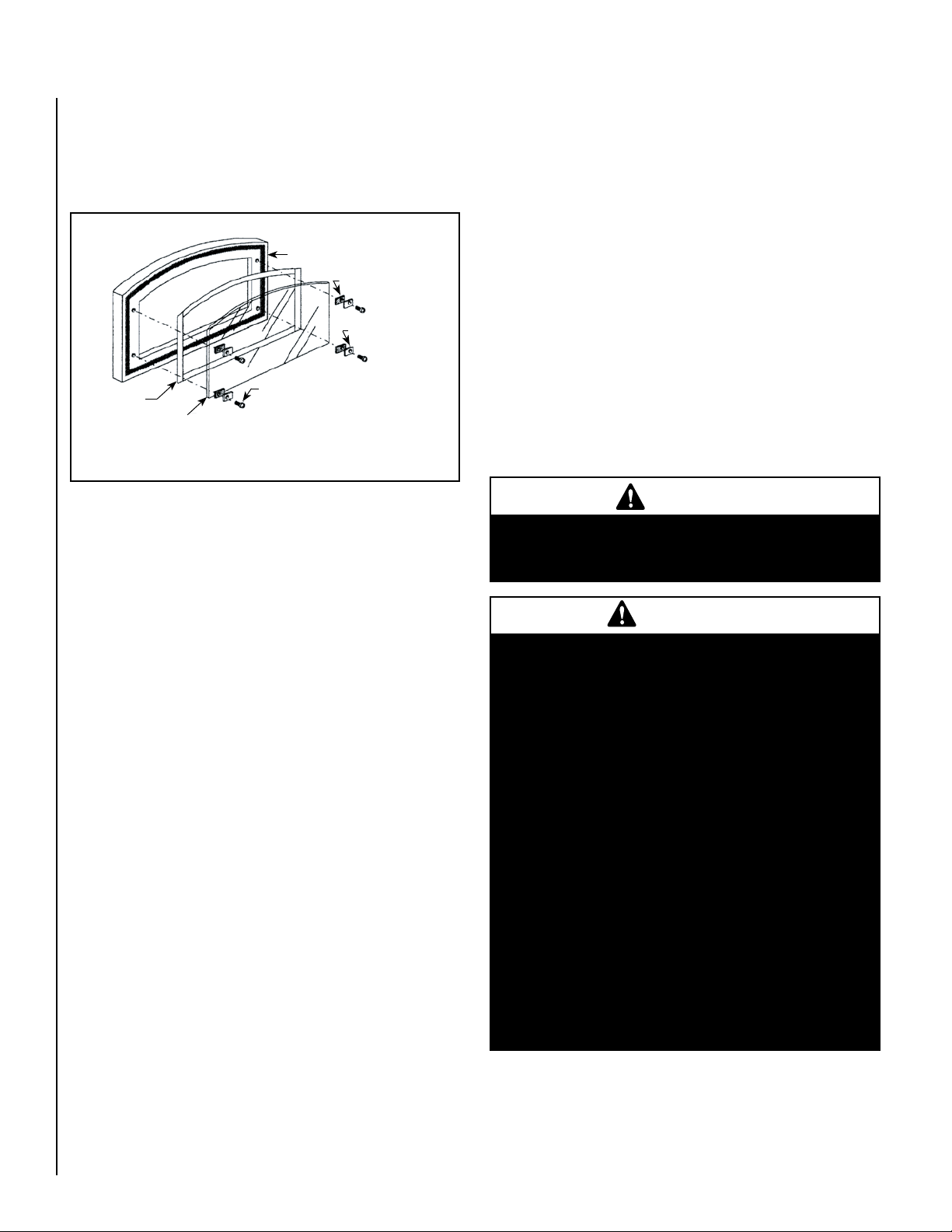
Replacing Glass:
Door Frame
4 Ea. Clip
Gaskets
4 Ea. Glass
Clips
4 Ea. Glass Clip Screws
Glass
Glass
Gasket
1. Open the door. Using a phillips screwdriver loosen the four (4) screws
which secure the glass then carefully remove broken glass one piece
at a time (protective leather gloves are recommended).
2. Remove screws and clips from doorframe and set aside.
Figure 15 - Replacing Glass
Cleaning - Remove the baffle brick in the firebox prior to having your
chimney cleaned (should be done by a qualified chimney sweep). See
following – Removing Baffle Brick for Cleaning).
Removing Baffle for Cleaning
Before flue can be cleaned, the baffle in the stove firebox must be removed.
The CI1000HT has one vermiculite firebrick, which serves as a baffle for
the flue gasses. The CI2000HT has a 5-sided box made of ceramic fiber
brick that serves as a baffle. In both cases, the baffles are located just
above the secondary air tubes (which must be removed to access the
baffle). Suggestion: Wear a pair of leather work gloves when removing
secondary air tube assembly and baffle.
1. To access the baffle, the secondary air tube assembly must be removed.
Locate the four (4) screws, which secure the assembly into place
(located at the ceiling of the firebox). Remove the assembly and set
aside. Slide the baffle out and set aside.
2. Once the baffle is removed from the firebox, the flue can be cleaned.
The accumulated soot that is removed by brushing will fall to the
firebox floor where it can be removed and disposed of.
3. Clean the area where the glass with gasket will be installed.
4. Install new glass with gasket (use only factory 4-mm glass with glass
channel gasket. Do not substitute).
5. Carefully reinstall glass clips with gasket and screws. Be very careful
not to overtighten the screws (this could result in breakage when
stove is hot).
Creosote Formation And Need For Removal
What is Creosote - When wood is burned slowly, it produces tar and
other organic vapors, which combine with expelled moisture to form
creosote. The creosote vapors condense in the relatively cool chimney
flue of a slow-burning fire. As a result, creosote residue accumulates
on the flue lining. When ignited this creosote makes an extremely hot
fire. Also, creosote deposits tend to form in long runs of venting where
gases become too cool prior to exhausting. Note: Single wall pipe cools
rapidly, therefore installations using this type of flue are more susceptible
to creosote deposits.
To inhibit the build up of creosote, adjust the primary air draft control to
a medium-high or high setting for a 10-minute period each day. Do not
attempt to burn out heavy creosote accumulations in this manner. This
must be removed from the chimney by scraping or brushing to reduce
the risk of a chimney fire.
Burn Approved Fuel Only - This stove is approved for burning dry seasoned natural wood only. Using green or inadequately seasoned wood
may increase creosote buildup.
Inspection Frequency - The chimney connector and chimney should
be inspected at least twice monthly during the heating season to determine if a creosote buildup has occurred. If creosote has accumulated it
should be removed to reduce the risk of a chimney fire. If creosote has
accumulated (1/8" [3 mm] or more) it should be removed to reduce the
risk of a chimney fire. Experienced chimney servicing personnel should
be consulted.
WARNING
Do NOT operate the stove without the baffle brick
properly installed. This will void the warranty and
the stove will not function properly.
IMPORTANT
IN THE EVENT OF A CHIMNEY FIRE - Make sure the
fuel loading doors are securely closed. Adjust the
primary air draft control to the lowest (most closed)
setting and ensure that the start-up air control is
closed. Call the fire department immediately.
After a chimney fire, the complete chimney system
should be checked by a qualified technician before
further use.
Consult your dealer for suggestions on proper chimney care. Contact your local municipal or provincial
fire authority for information on how to handle a
chimney fire. Have a clearly understood plan for
handling a chimney fire. Establish a routine for the
fuel, stove and firing technique. Check daily for
creosote build-up until experience shows how often
you need to clean to be safe. Be aware that the
hotter the fire the less creosote is deposited, and
weekly cleaning may be necessary in mild weather
even though monthly cleaning may be enough in
the coldest months.
Reinstall Baffle Brick
After your chimney has been swept, reinstall the baffle brick (see Removing Baffle for Cleaning and reverse steps).
20
NOTE: DIAGRAMS & ILLUSTRATIONS ARE NOT TO SCALE
Page 21

TROUBLESHOOTING
* When Fuel Door Is Opened, Smoke Enters Room
1. The primary air draft control is closed.
2. The chimney is too cool. Set the primary air draft control on “HIGH”
for a few minutes before opening either fuel loading door.
3. Excess creosote will not only restrict your draft but it will create a
risk of a creosote fire. Strictly adhere to maintenance requirements as
outlined in this manual. If excess creosote has built up on the inside
of the firebox sides and door, burn a small hot fire at intervals that
are more frequent with air control on HIGH for a few minutes.
4. Deposits may have built up in the chimney and are restricting the
draft, or the spark arrester on top of the chimney may be plugged.
5. Chimney diameter too large or too small to provide adequate draft.
6. The house is too airtight (usually takes 20 to 30 minutes for problem
to appear as stove lowers air pressure in house). Crack a window
open or provide an outside source of air near stove.
7. Insufficient vertical height to chimney to achieve adequate draft.
Does Not Produce Enough Heat
1. Using green or insufficiently cured wood.
2. Excessive draft.
3. High ceilings (heat rises quickly, but can be recirculated by a wellplaced ceiling fan with a winter/summer switch).
4. The area to heat is too large (square foot heating estimates are based
on “average” climates and home design).
5. There is an obstruction in the chimney.
6. The chimney or chimney cap is restricted by creosote preventing
enough draw to sustain a “high” heat output rate.
* Does Not Maintain A Fire
1. Soft wood does not burn as long or as well as seasoned hardwood
resulting in a short burn time.
2. Wood size too small. Burns at too rapid a rate.
3. The gasket seal on the fuel loading doors, or glass is leaking air. Repair
or replace it if necessary.
4. Excessive draft.
5. There may be an obstruction in the chimney.
* Backpuffing
Definition: This is a term describing the condition when combustible
gases remain unlit because of insufficient combustion air delivery which
results in combustible gases building, then flash igniting. If backpuffing
is occurring, it can push some smoke into the room through the primary
or secondary air openings. The combustion air delivery is dependent
upon the draft of the venting system. The following are variables, which
can negatively affect the draft resulting in backpuffing.
1. Downdraft in the chimney (a special wind cap may be needed).
2. The house is too air tight (ventilation is needed).
3. Insufficient vertical height to chimney to achieve adequate draft.
Odors
1. Creosote accumulation in firebox (brush out on next cleaning).
2. Chimney downdraft when stove is not operating (close the primary
air draft control).
3. Paint curing on first several burns.
* Draft problems; if installing into a larger flue, it may be necessary
to use a full-length liner to achieve adequate draft for the appliance.
A draft gauge should read a minimum of .05” W.C. (inches water
column) not to exceed .06” W.C. for optimum performance (See Draft
Requirements on Page 11).
OVERFIRING DAMAGE
If the heater or chimney connector glows, you are overfiring. Other symptoms may include: Cracking, warping or burning out of components, stove
glass may develop a haze, which will not come off with cleaning.
Overfiring of a stove is a condition where excessive temperatures are
reached, beyond the design capabilities of the appliance. The damage
that occurs from overfiring is not covered under the manufacturers
limited warranty.
The following are a few conditions that should be evaluated and (corrected
if necessary) if an overfiring condition is suspected:
Overfiring Caused From Improper Installation
Ensure that all installation requirements have been met as outlined in the
installation manual. The chimney should be clean and in good repair. A
draft test should be performed to determine if the draft requirements of
the appliance are being met. A draft gauge should read between .05 and
.06 “ W.C. (inches water column). Excessive draft (above .06 “ W.C.) will
allow too much combustion air to be pulled in which results in hotter
burns. Too little draft (below .05 “ W.C.) will not allow enough combustion air delivery to maintain a fire (this may result in improper operation
of appliance, i.e. wont maintain fire unless fuel loading door is left open.
See following, Overfiring Caused From Improper Operation).
Overfiring Caused From Improper Operation
Operate this appliance only as outlined in this manual. Never burn the
appliance with either fuel loading door open or ajar. Do not operate this
stove with the Primary Air Draft Control in the full “open” position for
extended periods. This wastes fuel and can cause dangerous overfiring
conditions. NEVER leave the stove unattended on high settings.
Overfiring Caused From Improper Maintenance
Strictly adhere to all maintenance requirements at frequent intervals as
prescribed in this manual including cleaning of flue and stove. Should
either fuel loading door or glass gaskets become worn or damaged, they
should be replaced.
Overfiring Caused From Improper Fuel
This appliance is approved for use with natural dry well-seasoned wood
only (ask your authorized dealer what are approved fuels for your area).
Do not burn garbage, particleboard scraps, or pressed logs because
they can produce conditions that will deteriorate metal. Do not overload
or use kindling wood or mill ends as primary fuel as this may cause
overfiring.
* Dirty Glass
1. Poor draft conditions.
2. Long burn periods at low draft settings.
3. Burning wet, pitchy or spongy wood.
4. Poorly arranged logs (too close to glass).
21
Page 22

SPECIFICATIONS - Model CI1000HT
Flue position Top
Flue collar size 6” (152 mm)
Approx. burn time 6 to 8 hours
Maximum burn rate 87,301 BTU
EPA BTU Range 11,500 – 55,000 BTU
Emissions Rate (grams/hr) 4.42 grams
Maximum Log length 18” (457 mm)
Firebox Size 1.12 cu. feet
Loading Front & Side
Width (overall) 23-3/4” (604 mm)
Depth (overall) 15-5/16” (389 mm)
Height (to flue) 30” (762 mm)
Height (to stove top) 27-1/4” (693 mm)
FRONT VIEW
23-3/4"
(604 mm)
6"
(152 mm)
30"
(762 mm)
27-1/4"
(693 mm)
4-1/8"
(105 mm)
* Shown with optional window trim
Back to centerline of flue 6-7/16” (163 mm)
Approx. weight with brick ~280 lbs. (140 kg)
Note: Dimensions shown are approximate only (+/- 1/4”).
SIDE VIEW
8-15/16"
(226 mm)
15-5/16"
(389 mm)
6-7/16"
(163 mm)
22
17-3/16"
(436 mm)
NOTE: DIAGRAMS & ILLUSTRATIONS ARE NOT TO SCALE
Page 23
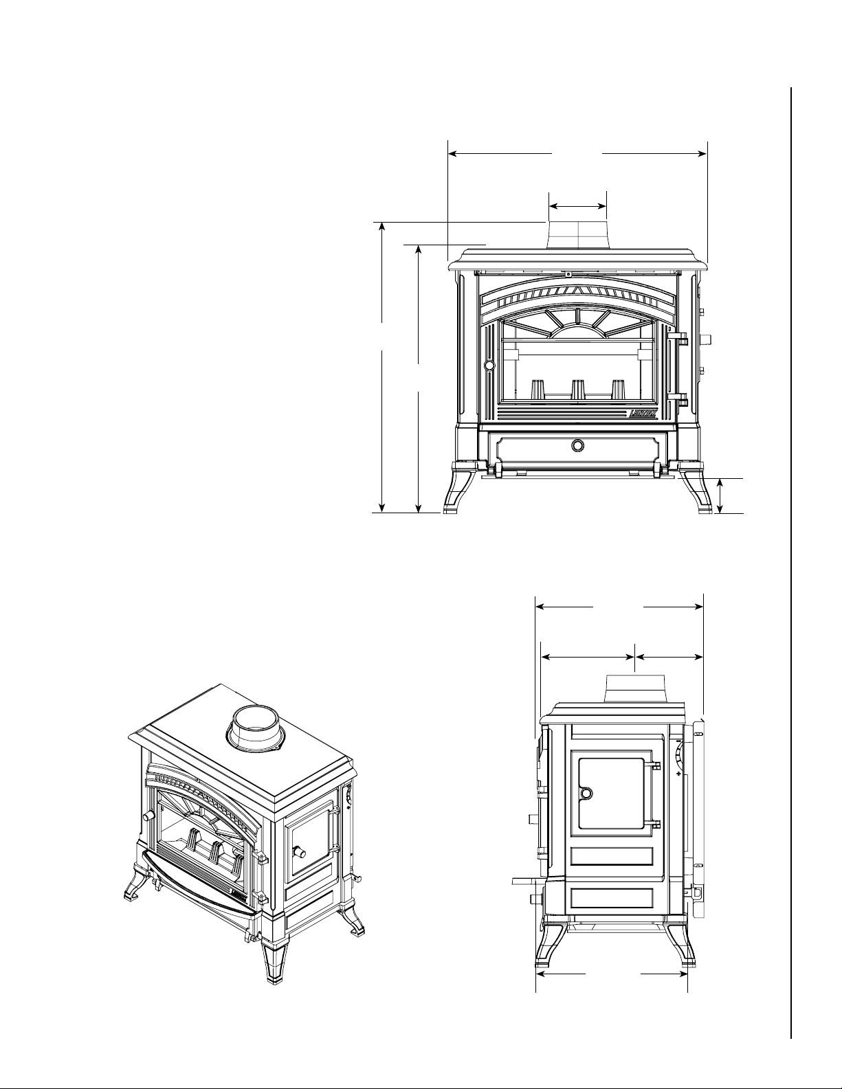
SPECIFICATIONS - Model CI2000HT
Flue position Top
Flue collar size 6” (152 mm)
FRONT VIEW
29-1/8"
(740 mm)
Approx. burn time 6 to 8 hours
Maximum burn rate 96,662 BTU
EPA BTU Range 11,923 – 60,897 BTU
Emissions Rate (grams/hr) 2.72 grams
Maximum Log length 22” (559 mm)
32-13/16"
(833 mm)
Firebox Size 1.97 cu. feet
Loading Front & Side
Width (overall) 29-1/8” (740 mm)
Depth (overall) 18-3/4” (476 mm)
Height (to flue) 32-13/16” (833 mm)
Height (to stove top) 29-3/4” (756 mm)
Back to centerline of flue 7-11/16” (195 mm)
Approx. weight with brick ~410 lbs. (205 kg)
Note: Dimensions shown are approximate only (+/- 1/4").
29-3/4"
(756 mm)
6"
(152 mm)
* Shown with optional window trim
SIDE VIEW
18-3/4"
(476 mm)
10-3/4"
(274 mm)
(195 mm)
3-15/16"
(100 mm)
7-11/16"
NOTE: DIAGRAMS & ILLUSTRATIONS ARE NOT TO SCALE
21-9/16"
(547 mm)
23
Page 24
REPLACEMENT PARTS LIST - Models: CI1000HT & CI2000HT
Item Cat. No. Description Where Used
31 40M5701 Air Column Set, Left & Right (Includes Gaskets & Screws) CI1000HT
32 40M6901 Air Column Set, Left & Right (Includes Gaskets & Screws) CI2000HT
33 40M2301 Air Deflector (Air Wash), Upper (Includes Hardware) CI1000HT
34 40M9801 Air Deflector (Air Wash), Upper (Includes Hardware) CI2000HT
35 40M2101 Ashlip, Charcoal, Painted (Includes Gasket & Screws) CI1000HT
35 40M8601 Ashlip, Charcoal, Painted (Includes Screws) CI2000HT
36 40M3901 Ashpan Assembly CI1000HT
36 41M0501 Ashpan Assembly CI2000HT
40M3601 Back, Steel Stove (Includes Hardware) CI1000HT
41M0301 Back, Steel Stove (Includes Hardware) CI2000HT
37 40M5101 Baffle Assembly, ceramic fiber brick (Baffle Box) CI2000HT
38 41M0401 Channel Assembly, Start-Up Air (Includes Gasket And Hardware) CI2000HT
41M0101 Clip Set, Glass (Includes 4 Ea. Gaskets, Screws & Clips) CI1000HT & CI2000HT
39 40M2701 Collar Kit, Charcoal Replacement Flue (Includes Gasket & Hardware) CI1000HT
40 40M9001 Collar Kit, Charcoal Replacement Flue (Includes Gasket & Hardware) CI2000HT
3 40M0701 Door, Ashpan, Charcoal (Handle Receiver Not Included) CI1000HT
4 40M4301 Door, Ashpan, Charcoal (Handle Receiver Not Included) CI2000HT
1 40M1701 Door, Firebox, Charcoal (Handle Receiver Not Included) CI1000HT
1 40M8201 Door, Firebox, Charcoal (Handle Receiver Not Included) CI2000HT
2 40M1201 Door, Side Loading, Charcoal (Handle Receiver Not Included) CI1000HT
2 40M7801 Door, Side Loading, Charcoal (Handle Receiver Not Included) CI2000HT
47 40M3501 Draft Module, Air Intake (Slide Assembly) Includes Gasket & Hardware CI1000HT
48 41M0201 Draft Module, Air Intake (Slide Assembly) Includes Gasket & Hardware CI2000HT
12 41M3901 Firebrick, Left CI1000HT
13 41M3801 Firebrick, Lower Rear CI1000HT
14 41M4001 Firebrick, Right CI1000HT
15 41M3701 Firebrick, Baffle (vermiculite) CI1000HT
16 41M4101 Firebrick, Upper Rear CI1000HT
5 41M5501 Firebrick, Bottom Center CI2000HT
6 41M4901 Firebrick, Bottom Side (left or right) CI2000HT
7 41M5001 Firebrick, Left Lower CI2000HT
8 41M5101 Firebrick, Left Upper CI2000HT
9 41M5401 Firebrick, Lower Rear CI2000HT
10 41M5201 Firebrick, Right Lower CI2000HT
11 41M5301 Firebrick, Upper Rear CI2000HT
17 40M7201 Frame, Fuel Grate (bottom) CI1000HT
18 40M9301 Frame, Fuel Grate (bottom) CI2000HT
24
The item numbers correspond to component diagrams on Pages 26 through 30
Note:
Page 25

REPLACEMENT PARTS LIST - Models: CI1000HT & CI2000HT
Item Cat. No. Description Where Used
40M4501 Gasket Kit, 6 mm x 156 cm (14979) For Air Intake Slide & Glass & 4 ea. 6mm Glass
Clip Gaskets (31856)
40M0201 Gasket Kit, Ashpan Door Rope (8 mm Dia. X 97 cm) CI1000HT
40M4201 Gasket Kit, Rope (10 mm Dia. x 146cm) Ashpan Door - CI2000HT, Side & Front
Firebox Door - CI1000HT
40M4401 Gasket Kit, Rope (12 mm Dia. x 177 Cm) Front & Side Door CI2000HT CI2000HT
19 40M4901 Gasket Set, Air Column, 70mm X 45mm (Also Includes Start Up Air Channel - Model
CI2000HT Only)
41M3601 Gasket, Flue Outlet CI1000HT
40M5401 Glass, Replacement, 10.39” X 14.02” (Includes Gasket) CI1000HT
41M0801 Glass, Replacement, 18.82” X 12.52” (Includes Gasket) CI2000HT
20 40M4001 Grate Support Bar, Fuel CI1000HT
21 40M1301 Grate, Ash Removal CI1000HT
22 40M2901 Grate, Fuel CI1000HT
23 40M9601 Grate, Fuel CI2000HT
24 40M5301 Hinge Pin Set, Ashpan Door (Includes 2 Hinge Pins, 2 Acorn Nuts & 2 Washers) CI1000HT & CI2000HT
25 40M4101 Hinge Pin Set, Firebox Door (Includes 2 Hinge Pins, 2 Acorn Nuts & 4 Washers) CI1000HT
26 40M5601 Hinge Pin Set, Firebox Door (Includes 2 Hinge Pins, 2 Acorn Nuts & 4 Washers) CI2000HT
27 40M5801 Hinge Pin Set, Side Door (Includes Hinge Pins, 2 Acorn Nuts & 2 Washers) CI1000HT & CI2000HT
28 41M0901 Leg, Front Left, Charcoal (Includes Gasket & Hardware) CI1000HT & CI2000HT
28 40M9501 Leg, Front Right, Charcoal (Includes Gasket & Hardware) CI1000HT & CI2000HT
28 41M3101 Leg, Right & Left Rear, Charcoal (Includes Gasket & Hardware) CI1000HT & CI2000HT
29 40M2801 Log Guard (With 2 Andirons) CI1000HT
30 40M9701 Log Guard (With 3 Andirons) CI2000HT
40M68 Paint, Touch-Up Spray, Charcoal, 1 Spray Can CI1000HT & CI2000HT
41 40M6201 Poker, Fire CI1000HT & CI2000HT
42 40M5201 Receiver Assembly, Ashpan Door Handle (Includes Latch) CI1000HT
42 40M0301 Receiver Assembly, Ashpan Door Handle (Includes Latch) CI2000HT
42 40M1001 Receiver Assembly, Firebox Door Handle (Includes Latch) CI1000HT & CI2000HT
42 40M3801 Receiver Assembly, Side Door Handle (Includes Latch) CI2000HT
42 40M6101 Receiver Assembly, Side Door Handle (Includes Latch) CI1000HT
49 41M5601 Retainer Set, Firebrick (Includes 1 Left, 1 Right & 2 Rear Firebrick Retainers &
Hardware)
41M4201 Retainer, Firebrick Steel CI1000HT
43 40M6001 Secondary Air Tube Kit (Includes Screws) CI1000HT
44 40M0101 Secondary Air Tube Kit (Includes Screws & Washers) CI2000HT
45 41M1001 Tool, Ashpan Removal / Air Control CI1000HT & CI2000HT
46 40M5501 Tool, Removable Door Opener CI1000HT &.CI2000HT
41M0601 Tube, Front Air Feed CI2000HT
CI1000HT & CI2000HT
CI1000HT & CI2000HT
CI1000HT & CI2000HT
CI2000HT
The item numbers correspond to component diagrams on Pages 26 through 30
Note:
25
Page 26
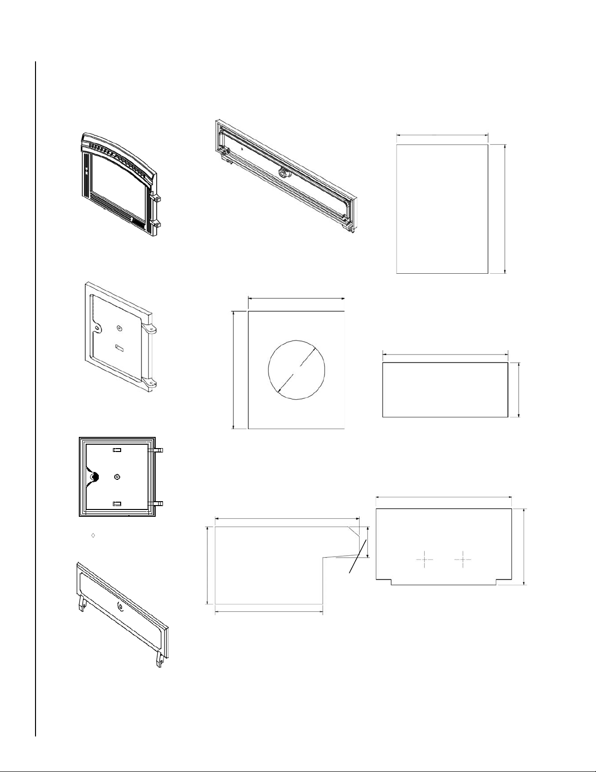
(1) Front Firebox Door
(CI1000HT & CI2000HT Series)
(2) Side Loading Door
(CI1000HT Series)
(2) Side Loading Door
(CI2000HT Series)
(
i3) Ashpan Door
(CI1000HT Series)
(4) Ashpan Door
(CI2000HT Series)
(5) Bottom Center Firebrick
(CI2000HT Series)
(6) Bottom Side Firebrick
(CI2000HT Series)
(7) Left Lower Firebrick
(CI2000HT Series)
(8) Upper Left Firebrick
(CI2000HT Series)
(
i9) Lower Rear Firebrick
(CI2000HT Series)
4.6” / 117 mm
7.87” x 200 mm
9.25 ´/ 235 mm
12.36” / 314 mm
9.25” / 235 mm
2.87” / 73 mm
7.87” / 200 mm
.79” / 20 mm thick
7.87” / 200 mm
10.08” / 256mm
.79” / 20 mm thick
10.43” / 265 mm
5.51” / 140 mm
.79” / 20 mm thick
13.94” / 354 mm
7.87” x 200 mm
.79” / 20 mm thick
REPLACEMENT PARTS - Models: CI1000HT & CI2000HT
26
NOTE: DIAGRAMS & ILLUSTRATIONS ARE NOT TO SCALE
Page 27
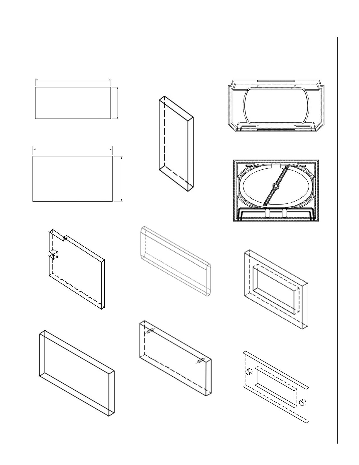
(10) Right Lower Firebrick
(CI2000HT Series)
(11) Upper Rear Firebrick
(CI2000HT Series)
(12) Left Firebrick
(CI1000HT Series)
(13) Lower Rear Firebrick
(CI1000HT Series)
(14) Right Firebrick
(CI1000HT Series)
8.47” / 215 mm x 5.12” /
130mm (.98” / 25mm thick)
(15) Baffle Firebrick
(above tubes on ceiling)
(CI1000HT Series)
(16) Upper Rear Firebrick
(CI1000HT Series)
(17) Fuel Grate Frame
(CI1000HT Series)
(18) Fuel Grate Frame
(CI2000HT Series)
(19) Air Column Gasket
(CI1000HT & CI2000HT Series)
(19) Start-up Air Column Gasket
(CI2000HT Series)
10.43” / 265 mm
4.72” / 120 mm
.79” / 20 mm thick
13.93” / 354 mm
7.87” / 200 mm
.79” / 20 mm thick
8.47” / 215 mm
x 12” / 305 mm
(.79” / 20mm
thick)
6.50” / 165mm
x 12.40” / 315 mm
(.98” / 25 mm thick
)
5.87” / 149 mm
x 14.36” / 365 mm
(.98” / 25 mm thick
)
5.51” / 140mm
x 12.60” / 320 mm
(.98” / 25 mm thick
)
REPLACEMENT PARTS - Models: CI1000HT & CI2000HT
NOTE: DIAGRAMS & ILLUSTRATIONS ARE NOT TO SCALE
27
Page 28

REPLACEMENT PARTS - Models: CI1000HT & CI2000HT
(20) Fuel Grate Support Bar
(CI1000HT Series)
(21) Ash Removal Grate
(CI1000HT Series)
(22) Fuel Grate
(CI1000HT Series)
(23) Fuel Grate
(CI2000HT Series)
(24) Ashpan Door Hinge Pin
(CI1000HT & CI2000HT Series)
(25) Front Firebox Door Hinge Pin
(CI1000HT Series)
(26) Front Firebox Door Hinge Pin
(CI2000HT Series)
(27) Side Door Hinge Pin
(CI1000HT & CI2000HT Series)
(28) Stove Leg
(CI1000HT & CI2000HT Series)
(29) Log Guard
(C1000HT Series)
(30) Log Guard
(CI2000HT Series)
(31) Left Air Column Assembly
(CI1000HT Series)
(31) Right Air Column Assembly
(CI1000HT Series)
REPLACEMENT PARTS - Models: CI1000HT & CI2000HT
28
NOTE: DIAGRAMS & ILLUSTRATIONS ARE NOT TO SCALE
Page 29

(32) Left Air Column Assembly
(CI2000HT Series)
(32) Right Air Column Assembly
(CI2000HT Series)
(33) Upper Air Deflector
(CI1000HT Series)
(34) Upper Air Deflector
(CI2000HT Series)
(35) Ashlip
(CI1000HT & CI2000HT Series)
(36) Ashpan
(CI1000HT & CI2000HT Series)
(37) Baffle Assembly, Ceramic Fiber Brick
(above secondary air tubes)
(CI2000HT Series)
(38) Start-up Air Channel Assembly
(CI2000HT Series)
(39) Flue Outlet Collar
(CI1000HT Series)
(40) Flue Outlet Collar
(CI2000HT Series)
(41) Fire Poker
(CI1000HT & CI2000HT Series)
(42) Ashpan, Side Door and Firebox
Door Handle Receivers
(CI1000HT & CI2000HT Series)
Side View
Top View
REPLACEMENT PARTS - Models: CI1000HT & CI2000HT
NOTE: DIAGRAMS & ILLUSTRATIONS ARE NOT TO SCALE
29
Page 30

REPLACEMENT PARTS - Models: CI1000HT & CI2000HT
REPLACEMENT PARTS - Models: CI1000HT & CI2000HT
(43) Secondary Air Tube Assembly
(CI1000HT Series)
(44) Secondary Air Tube Assembly
(CI2000HT Series)
(45) Air Control/Ash Pan Removal Tool
(CI1000HT & CI2000HT Series)
(46) Removable Door Opener Tool
(CI1000HT & CI2000HT Series)
(47) Draft Module (Air Intake Slide)
(CI1000HT Series)
(48) Draft Module (Air Intake Slide)
(CI2000HT Series)
(49) Rear Firebrick Retainers
(CI2000HT Series)
Side Retainers Not Shown
CI1000HT Firebrick Placement Diagram
(15) Baffle Firebrick
(16) Upper Rear Firebrick
(13) Lower Rear Firebrick
(12) Left Side
Firebrick
(14) Right Side
Firebrick
Note:
CI1000HT does
not have firebrick on firebox floor (fuel
grate & frame
on floor only).
CI2000HT Firebrick Placement Diagram
(11) Upper
Rear Firebrick
(9) Lower
Rear Firebrick
(8) Upper
Left Firebrick
(7) Lower
Left Firebrick
(6) Bottom
Side
Firebrick
(6) Bottom
Side
Firebrick
(5) Bottom Center
Firebrick
(10) Lower
Right Firebrick
BACK WALL
BACK WALL
CEILING
LEFT WALL
LEFT WALL RIGHT WALL
FLOOR
RIGHT WALL
Note: The refractory baffle assembly (37) on ceiling (above tubes), not shown.
30
NOTE: DIAGRAMS & ILLUSTRATIONS ARE NOT TO SCALE
NOTE: DIAGRAMS & ILLUSTRATIONS ARE NOT TO SCALE
Page 31

OPTIONAL ACCESSORIES - Models CI1000HT & CI2000HT
Catalog No. Model Description Stove Model
41M2401 WTK-CI10 Window Trim Kit, Charcoal CI1000HT
41M2001 WTK-CI20 Window Trim Kit, Charcoal CI2000HT
NOTE: DIAGRAMS & ILLUSTRATIONS ARE NOT TO SCALE
31
Page 32

SAFETY/LISTING LABEL – Model CI1000HT
Chimney & Dimensions
Installation Clearance Connector A B C D E** F**
U.S. Residential Standard Note: 1 27.50 27.00 27.00 24.00 18.00 19.00
(in inches) Residential Reduced Note: 1, 2 21.50 27.00 19.00 18.00 18.00 11.00
** “E” dimension is measured to side of stove below the projection of outer top.
Note 1: 6 inch diameter, single wa ll, minimum 2 4 MS G black or 25 MS G blu ed steel
connector pipe with factory-built chimney listed to either UL 103HT or ULC S629.
Note 2: Pipe shield for 6" connector with 1 inch clearance to pipe.
Espaces Cheminée Dimensions
Installation Libres et Tuyau A B C D E** F**
Canada Résidentielle Standard Note: 1 698 686 686 610 457 483
(en mm) Résidentielle Réduits Note: 1, 2 546 686 483 457 457 279
** Les dimension “E” est mesurées du côté du poêle en dessous de la projection
extérieure du haut du poéle.
Note 1: Le tuyau connecteur en acier noir de minimum 24 MSG ou en acier bleu de 25 MSG, de 6”
de diamètre, pour mur simple, avec cheminée faite en usine, enregistrée sous ULC S-629.
Note 2: Pour la buse de 6”, le protecteur doit être positionné à au minimum 1” de celle-ci.
CONTACT YOUR LOCAL BUILDING OR FIRE OFFICIALS ABOUT RESTRICTIONS AND INSTALLATION INSPECTION IN YOUR AREA
CONTACTEZ LE BUREAU DE LA CONSTRUCTION OU LE BUREAU DES INCENDIES AU SUJET DES RESTRICTIONS ET DES INSPECTIONS D’INSTALLATION DANS VOTRE VOISINAGE
Listed Room Heaters, Solid Fuel Type
/ Appareil de Chauffage de Pièce, de Combustibles Solides
FOR USE WITH SOLID WOOD FUEL ONLY / POUR USAGE AVEC LE BOIS SEULEMENT
"PREVENT HOUSE FIRES"
Install and use only in accordance with manufacturer's installation instructions and your local
building codes.
CAUTION: Special methods are required when passing chimney through a wall or ceiling, refer
to installation instructions and local building codes. Do not pass chimney connector through a
combustible surface. Do not connect this unit to a chimney flue serving another appliance.
NOTE: Replace glass only with 5mm ceramic. Operate with the doors closed.
"PRÉVENTION DES FEUX DE MAISON"
Installez et utilisez en accord avec les instructions d’installation du fabricant et des codes locaux.
AVIS: Prenez des précautions spéciales lorsque vous faites passer une cheminée à travers un
mur ou un plafond, référez-vous aux instructions d’installation et aux codes locaux de la
construction. Ne pas faire passer le tuyau de cheminée à travers une surface combustible. Ne
pas connecter cet appareil à un tuyau de cheminée servant un autre appareil.
NOTE: Remplacez la vitre avec une céramique de 5mm seulement. Opérez avec les porte fermée.
Serial No. / Numéro de Série
Model / Modèle: CI 1000HT
Tested To / Testé à: UL 1482, ULC-S627
Floor protector must be a 1/2" minimum
thick nes s, no n-comb usti ble m ater ial
(having an equal or better insulating value
(lower k Value) of k=.84 BTU/In Ft2Hr F.
It must extend beneath heater, and to the
front/sides/rear as indicated.
*In Can ada, r equired fl oor protection
mu st be a 1. 45" min imu m t hic kne ss
extending 18" (450 mm) in front and 8"
(2 00m m) on a ll o the r s ide s o f th e
appliance.
Le protecteur d e planc her doit être d'un e
épaisseur m inimum de 1/2" , d'un matér iel
incombustible ayant une valeur d'isolation
de k=.84 BTU/In Ft2Hr F.
Il doit s'étendre en dessous de l'appareil et
au d eva nt, aux côtés et à l'a rri ère de
l'appareil comme indiqué.
*Au Canada, la protection de sol nécessaire
doit avoir une épaisseur de minimum 1.45”
et dépas ser l ’avant d e l’a ppar eil de 18”
(450mm) et le autres côtés de 8” (200mm).
45°
ADJACENT WALL
MUR ADJACENT
ADJACENT WALL
MUR ADJACENT
BACKWALL
MUR ARRIÈRE
SIDEWALL
MUR DE CÔTÉ
A
B
C
D
E**
F
Manufactured for / Fabriqués pour:
LENNOX HEARTH PRODUCTS
1110 West Taft Avenue
Orange, CA 92865
U.S. ENVIRONMENTAL PROTECTION AGENCY
Certified to comply with July 1990 particulate emission standards.
Date of Manufacture / Date de Fabrication
20 06 20 07 20 08 Ja n. Feb. Mar. A pr. May Ju ne July Aug . Sept. Oct . Nov. Dec.
DO NOT REMOVE THIS LABEL / NE PAS ENLEVER CETTE ÉTIQUETTE Made in Belgium by FDL
Report No. / Numéro de Rapport 132-S-03-2
IGN P/N 775111M, Rev. A
FLOOR PROTECT
OR
PROTECTEUR DE PLANCHER
5.2"
5.2"
0"
18"
*8" (200mm)
*8" (200mm)
*8" (200mm)
(450mm)
CAUTION:
HOT WHILE IN OPERATION. DO NOT TOUCH.
CO NTACT MAY CAUSE SKIN BURNS. KEEP CHIL DREN, CLOTHING,
FURNISH INGS AND C OMBUSTIBL E MATERIAL A CONSIDER ABLE
DISTANCE AWAY. SEE NAMEPLATE AND I NSTRUCTIONS. DO NOT
OVERFIRE. IF HEATER OR CHIMNEY CONNECTOR GLOWS, YOU ARE
OVERF IRING. INSPECT AND CLEA N C HIMNEY AND CONN ECTOR
FREQUEN TLY. UNDE R CERTAIN CONDI TION S OF USE, CREOSOTE
BUILDUP MAY OCCUR RAPIDLY. DO NOT USE GRATE OR ELEVATE FIRE - BUILD
WOOD FIRE DIRECTLY ON HEARTH. DO NOT BURN WITH FEED DOORS OPEN. FEED
DOORS MUST BE CLOSED DURING FIRING EXCEPT WHEN ADDING FUEL. OPEN
COMBUSTION AIR CONTROL BEFORE OPENING FEED DOORS.
ATTENTION:
CHAUD LORS DE L’OPÉRATION. NE PAS TOUCHER. LE
CONTACT PEUT CAUSER DES BRÛLURES À LA PEAU. GARDEZ LES ENFANTS, LES
VÊTEMENTS, LES MEUBLES ET LES MATÉRIAUX COMBUSTIBLES LOIN DE L’ESPACE
DÉSIGNÉ DE L’APPAREIL. VOIR L’ÉTIQUETTE ET LES INSTRUCTIONS. NE PAS
SURCHAUFFER. SI L’APPAREIL DE CHAUFFAGE OU LE TUYAU DE CHEMINÉE
ROUGISSENT, VOUS SURCHAUFFEZ. INSPECTEZ ET NETTOYEZ LA CHEMINÉE ET LE
TUYAU CONNECTEUR FRÉQUEMMENT. SOUS CERTAINES CONDITIONS, IL SE PEUT QUE
LA CRÉOSOTE S’ACCUMULE RAPIDEMENT. N’ÉLEVEZ PAS LE FEU. BÂTISSEZ LE FEU DE BOIS
DIRECTEMENT SUR L’ÂTRE. NE PAS BRÛLER LORSQUE LES PORTE D’OUVERTURE EST OUVERTE.
LES PORTE D’OUVERTURE DOIT ÊTRE FERMÉE PENDANT L’USAGE EXCEPTÉ PENDANT QUE VOUS
AJOUTEZ DU FEU. OUVREZ LE TUYAU D’AIR AVANT D’OUVRIR LES PORTE D’OUVERTURE.
US
32
NOTE: DIAGRAMS & ILLUSTRATIONS ARE NOT TO SCALE
Page 33
SAFETY/LISTING LABEL – Model CI2000HT
Chimney & Dimensions
Installation Clearance Connector A B C D E** F** G H
U.S. Residential Standard Note: 1 18.00 32.00 27.00 13.00 20.00 16.00 29.00 60.00
(in inches) Residential Reduced Note: 2 14.50 28.50 18.00 10.00 17.00 7.00 29.00 60.00
Residential Alcove Note: 2,3 14.50 28.50 N/A 10.00 17.00 N/A 29.00 60.00
** “E” dimension is measured to side of stove below the projection of outer top.
Note 1: 6 inch diameter, single wall, m inimum 24 M SG black or 25 MSG b lued steel
connector pipe with factory-built chimney listed to either UL 103HT or ULC S629.
Note 2: 6 inch diameter listed double wall chimney connector or Type L vent pipe between the
stove and chimney.
Note 3: Maximum alcove depth must be no more than 48” (1220mm).
Espaces Cheminée Dimensions
Installation Libres et Tuyau A B C D E** F** G H
Canada Résidentielle Standard Note: 1 457 813 686 330 508 406 737 1524
(en mm) Résidentielle Réduits Note: 2 368 724 457 254 864 178 737 1524
Résidentielle Alcôve Note: 2,3 368 724 N/A 254 864 N/A 737 1524
** Les dimension “E” est mesurées du côté du poêle en dessous de la projection
extérieure du haut du poéle.
Note 1: Le tuyau connecteur en acier noir de minimum 24 MSG ou en acier bleu de 25 MSG, de 6”
de diamètre, pour mur simple, avec cheminée faite en usine, enregistrée sous ULC S-629.
Note 2: Le tuyau connecteur de 6” de diamètre, pour mur double ou un connecteur de cheminée de
type L entre le poêle et la cheminée.
Note 3: La profondeur maximum de l’alcove ne peut dépasser 48” (1220mm).
CONTACT YOUR LOCAL BUILDING OR FIRE OFFICIALS ABOUT RESTRICTIONS AND INSTALLATION INSPECTION IN YOUR AREA
CONTACTEZ LE BUREAU DE LA CONSTRUCTION OU LE BUREAU DES INCENDIES AU SUJET DES RESTRICTIONS ET DES INSPECTIONS D’INSTALLATION DANS VOTRE VOISINAGE
Listed Room Heaters, Solid Fuel Type
/ Appareil de Chauffage de Pièce, de Combustibles Solides
FOR USE WITH SOLID WOOD FUEL ONLY / POUR USAGE AVEC LE BOIS SEULEMENT
"PREVENT HOUSE FIRES"
Install and use only in accordance with manufacturer's installation instructions and your local
building codes.
CAUTION: Special methods are required when passing chimney through a wall or ceiling, refer
to installation instructions and local building codes. Do not pass chimney connector through a
combustible surface. Do not connect this unit to a chimney flue serving another appliance.
NOTE: Replace glass only with 5mm ceramic. Operate with the doors closed.
"PRÉVENTION DES FEUX DE MAISON"
Installez et utilisez en accord avec les instructions d’installation du fabricant et des codes locaux.
AVIS: Prenez des précautions spéciales lorsque vous faites passer une cheminée à travers un
mur ou un plafond, référez-vous aux instructions d’installation et aux codes locaux de la
construction. Ne pas faire passer le tuyau de cheminée à travers une surface combustible. Ne
pas connecter cet appareil à un tuyau de cheminée servant un autre appareil.
NOTE: Remplacez la vitre avec une céramique de 5mm seulement. Opérez avec les porte fermée.
Serial No. / Numéro de Série
Model / Modèle: CI 2000HT
Tested To / Testé à: UL 1482, ULC-S627
Floor protector mu st be a 1/2"
minimum thickness, non-combustible
material (having an equal or better
insulating value (lower k Value) of
k=.84 BTU/In Ft2Hr F.
It must extend beneath heater, and to
the front/sides/rear as indicated.
*In Canada, required floor protection
must be 18” (450mm) in front and 8”
(200m m) on all other sides of the
appliance.
Le protecteur de plancher doit être d'une
épaisseur minimum de 1/2", d'un matériel
incombustible ayant une valeur d'isolation
de k=.84 BTU/In Ft2Hr F.
Il doit s'étendre en dessous de l'appareil et
au devant, a ux côtés et à l'arrière de
l'appareil comme indiqué.
*Au Canada, la protection du plancher doit
s’étendre de 18” (450mm) en avant et de 8”
(200mm) sur tous les a utres côtés de
l’appareil.
45°
ADJAC ENT WALL
MUR ADJACENT
ADJACENT WALL
MUR ADJACENT
BACKWALL
MUR ARRIÈRE
SIDEWALL
MUR DE CÔTÉ
A
B
C
D
E**
F
ALCO VE WALL
MUR DE ALCÔVE
POÊLE
G H
STOVE
Manufactured for / Fabriqués pour:
LENNOX HEARTH PRODUCTS
1110 West Taft Avenue
Orange, CA 92865
U.S. ENVIRONMENTAL PROTECTION AGENCY
Certified to comply with July 1990 particulate emission standards.
Date of Manufacture / Date de Fabrication
20 06 20 07 20 08 Ja n. Feb. Mar. A pr. May Ju ne July Aug . Sept. Oct . Nov. De c.
DO NOT REMOVE THIS LABEL / NE PAS ENLEVER CETTE ÉTIQUETTE Made in Belgium by FDL
Report No. / Numéro de Rapport 132-S-05-2
IGN P/N 775112M, Rev. A
FLOOR PROTECTOR
PROTECTEUR DE PLANCHER
5"
5"
0"
18"
*8" (200mm)
*8" (200mm)
*8" (200mm)
(450mm)
CAUTION:
HOT WHILE IN OPERATION. DO NOT TOUCH.
CO NTACT MAY CAUSE SKIN BUR NS. KEEP CHIL DREN, CLOTHING,
FURNISH INGS AND C OMBUSTIBL E MATERIAL A CONSIDER ABLE
DISTANCE AWAY. SEE NAMEPLATE AND I NSTRUCTIONS. DO NOT
OVERFIRE. IF HEATER OR CHIMNEY CONNECTOR GLOWS, YOU ARE
OVERF IRING. INSPECT AND CLEA N C HIMNEY AND CONN ECTOR
FREQUEN TLY. UNDE R CERTAIN CONDI TION S OF USE, CREOSOTE
BUILDUP MAY OCCUR RAPIDLY. DO NOT USE GRATE OR ELEVATE FIRE - BUILD
WOOD FIRE DIRECTLY ON HEARTH. DO NOT BURN WITH FEED DOORS OPEN. FEED
DOORS MUST BE CLOSED DURING FIRING EXCEPT WHEN ADDING FUEL. OPEN
COMBUSTION AIR CONTROL BEFORE OPENING FEED DOORS.
ATTENTION:
CHAUD LORS DE L’OPÉRATION. NE PAS TOUCHER. LE
CONTACT PEUT CAUSER DES BRÛLURES À LA PEAU. GARDEZ LES ENFANTS, LES
VÊTEMENTS, LES MEUBLES ET LES MATÉRIAUX COMBUSTIBLES LOIN DE L’ESPACE
DÉSIGNÉ DE L’APPAREIL. VOIR L’ÉTIQUETTE ET LES INSTRUCTIONS. NE PAS
SURCHAUFFER. SI L’APPAREIL DE CHAUFFAGE OU LE TUYAU DE CHEMINÉE
ROUGISSENT, VOUS SURCHAUFFEZ. INSPECTEZ ET NETTOYEZ LA CHEMINÉE ET LE
TUYAU CONNECTEUR FRÉQUEMMENT. SOUS CERTAINES CONDITIONS, IL SE PEUT QUE
LA CRÉOSOTE S’ACCUMULE RAPIDEMENT. N’ÉLEVEZ PAS LE FEU. BÂTISSEZ LE FEU DE BOIS
DIRECTEMENT SUR L’ÂTRE. NE PAS BRÛLER LORSQUE LES PORTE D’OUVERTURE EST OUVERTE.
LES PORTE D’OUVERTURE DOIT ÊTRE FERMÉE PENDANT L’USAGE EXCEPTÉ PENDANT QUE VOUS
AJOUTEZ DU FEU. OUVREZ LE TUYAU D’AIR AVANT D’OUVRIR LES PORTE D’OUVERTURE.
US
NOTE: DIAGRAMS & ILLUSTRATIONS ARE NOT TO SCALE
33
Page 34

EPA LABELS – CI1000HT and CI2000HT
34
Page 35

OWNERSHIP RECORDS
Dealer’s Name:
Dealer’s Address:
City: State:
Serial Number:
Date Installed:
Date of Purchase:
Notes:
SERVICE AND MAINTENANCE LOG
Service Service Service
Date Technician Description
Zip Code:
35
Page 36
WARRANTY
Your wood appliance is covered by a limited warranty (provided with
appliance). Please read the warranty to be familiar with its coverage.
Retain this manual. File it with your other documents for future reference.
PRODUCT REFERENCE INFORMATION
We recommend that you record the following important information
about your fireplace. Please contact your Lennox Hearth Products dealer
for any questions or concerns. For the number of your nearest Lennox
Hearth Products dealer, please call 1-800-9-Lennox.
REPLACEMENT PARTS
See Pages 24 to 30 for a complete replacement parts list. Use only parts
supplied from the manufacturer.
Your Stove's Model Number __________________________________________
Normally, all parts should be ordered through your Lennox Hearth
Products distributor or dealer. Parts will be shipped at prevailing prices
at time of order.
When ordering repair parts, always give the following information:
1. The model number of the appliance.
2. The serial number of the appliance.
3. The part number.
4. The description of the part.
5. The quantity required.
6. The installation date of the appliance.
If you encounter any problems or have any questions concerning the
installation or application of this system, please contact your dealer.
LENNOX HEARTH PRODUCTS
1110 West Taft Avenue
Orange, CA 92865
Visit us at www.Lennox.com
Your Stove's Serial Number ___________________________________________
The Date On Which Your Stove Was Installed _____________________________
Your Dealer's Name _________________________________________________
Lennox reserves the right to make changes at any time, without notice, in design, materials, specifications, prices and also to discontinue colors, styles and products. Consult
your local distributor for fireplace code information.
Printed in U.S.A. © Lennox Hearth Products 2002
P/N 775,080M Rev. G 09/2007
36
1110 West Taft Avenue • Orange, CA 92865
 Loading...