

Page 1
CHA/CHP16
Service Literature
Corp. 0109-L2
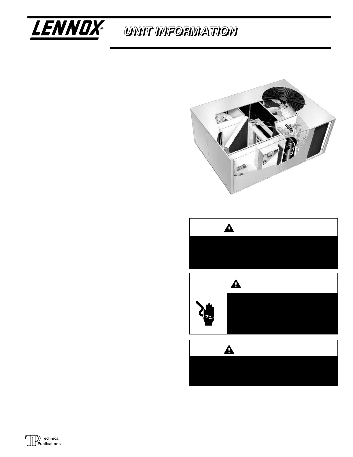
CHA/CHP16, CHP20 SERIES UNITS
CHA/CHP16 and CHP20 series units in the 2 through 5 ton
(7.0 through 17.6 kW) sizes are designed for outdoor roofĆ
top or ground level installations in light commercial applicaĆ
tions. Electric heat is available in several kW sizes. Models
are available in single or three phase power supply and can
be utilized in downflow or horizontal supply and return air.
CHA/CHP16-024/030 model units are equipped with a
reciprocating compressor. CHA/CHP16-036/060 and
CHP20-024/060 model units are equipped with scroll
compressors. The scroll compressor offers high voluĆ
metric efficiency, quiet operation and the ability to start
under system load. Continuous flank contact, mainĆ
tained by centrifugal force, minimizes gas leakage and
maximizes efficiency. The motor is internally protected
from excessive current and temperature.
CHA/CHP16 and CHP20 model units are designed to acĆ
cept any of several different thermostat control systems
with minimum field wiring. Control options such as econĆ
omizer, warm up kit, Honeywell T7300 thermostat or
Honeywell T8600/T8611/T8621 thermostat controls
connect to the unit with jackĆplugs. When plugged in the
controls become an integral part of the unit wiring. Low
voltage thermostat connections facilitate thermostat
field wiring.
Optional electric heat is field installed. Electric heat operĆ
ates in single or multiple stages depending on the kW size.
5kW through 25 kW sizes are available for the CHA/CHP16
and CHP20 units.
Information in this manual is for use by a qualified service
technicial only. All specifications in this manual are subject
to change. Procedures outlined in this manual are repesĆ
ented as a recommendation only and do not supersede or
replace state or local codes.
2 to 5 ton (7.0 to 17.6 kW)
CHP20
IMPORTANT
Improper installation, adjustment, alteration, service
or maintenance can cause property damage, personĆ
al injury or loss of life. Installation and service must
be performed by a qualified installer, service agency
or the gas supplier.
WARNING
Electric shock hazard. Can cause injury
or death. Before attempting to perform
any service or maintenance, turn the
electrical power to unit OFF at disconĆ
nect switch(es). Unit may have multiple
power supplies.
Page 1
WARNING
Refrigerant can be harmful if it is inhaled. Refrigerant
must be used and recovered responsibly.
Failure to follow this warning may result in personal
injury or death.
2001 Lennox Industries Inc.
Litho U.S.A.
Page 2
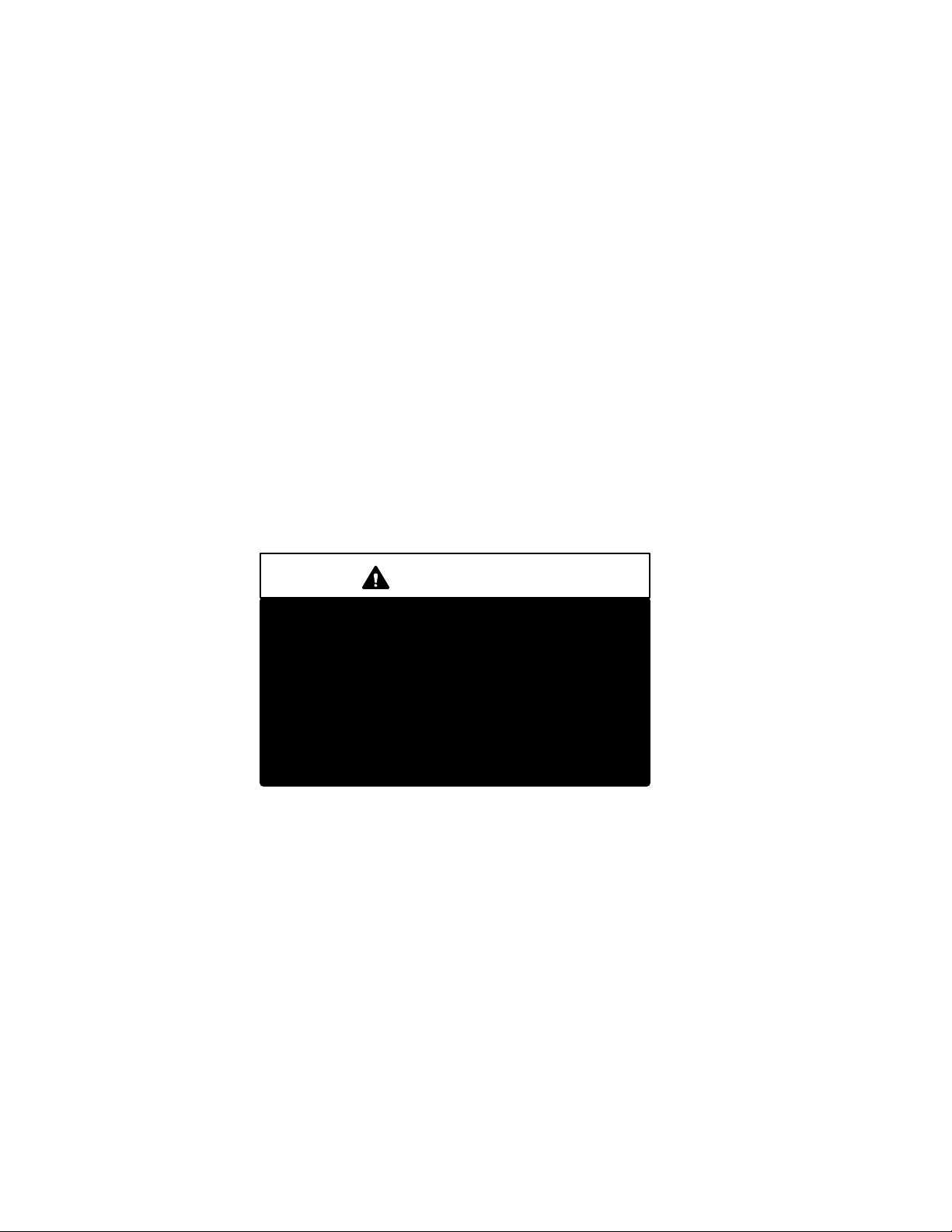
TABLE OF CONTENTS
GENERAL 1. . . . . . . . . . . . . . . . . . . . . . . . . . . . . . . .
SPECIFICATIONS CHA16 3. . . . . . . . . . . . . . . . . .
SPECIFICATIONS CHP16 4. . . . . . . . . . . . . . . . .
SPECIFICATIONS CHP20 5. . . . . . . . . . . . . . . . . .
OPTIONAL ACCESSORIES CHA/CHP16 6. . . .
OPTIONAL ACCESSORIES CHP20 7. . . . . . . . .
ELECTRICAL DATA CHA16 8. . . . . . . . . . . . . . . .
ELECTRICAL DATA CHP16/20 9. . . . . . . . . . . . .
BLOWER DATA CHA16 10. . . . . . . . . . . . . . . . . . . .
BLOWER DATA CHP16/20 13. . . . . . . . . . . . . . . . .
ACCESSORIES BLOWER DATA 16. . . . . . . . . . . .
I APPLICATION 18. . . . . . . . . . . . . . . . . . . . . . . . . . . . . . .
ELECTROSTATIC DISCHARGE (ESD)
Precautions and Procedures
II UNIT COMPONENETS 18. . . . . . . . . . . . . . . . . . . . . .
Control Box 18. . . . . . . . . . . . . . . . . . . . . . . . . . . . . . .
Cooling Components 22. . . . . . . . . . . . . . . . . . . . . . .
Condenser Fan and Indoor Blower 27. . . . . . . . . . .
III OPTIONAL ELECTRIC HEAT 28. . . . . . . . . . . . . . . .
IV PLACEMENT AND INSTALLATION 43. . . . . . . . . . .
V ELECTRICAL CONNECTIONS 43. . . . . . . . . . . . . . .
VI START UP 43. . . . . . . . . . . . . . . . . . . . . . . . . . . . . . . . .
VII COOLING SYSTEM SERVICE CHECKS 43. . . . . .
VIII HEATING SYSTEM SERVICE CHECKS 44. . . . . .
IX INDOOR BLOWER OPERATION 44. . . . . . . . . . . . .
X MAINTENANCE 45. . . . . . . . . . . . . . . . . . . . . . . . . . . . .
XI ACCESSORIES 46. . . . . . . . . . . . . . . . . . . . . . . . . . . .
XII WIRING AND OPERATION SEQUENCE 52. . . . . .
CAUTION
Electrostatic discharge can affect electronic
components. Take precautions during unit
installation and service to protect the unit's elecĆ
tronic controls. Precautions will help to avoid
control exposure to electrostatic discharge by
putting the unit , the control and the technician at
the same electrostatic potential. Neutralize elecĆ
trostatic charge by touching hand and all tools on
an unpainted unit surface, such as the blower
deck, before performing any service procedure.
Page 2
Page 3
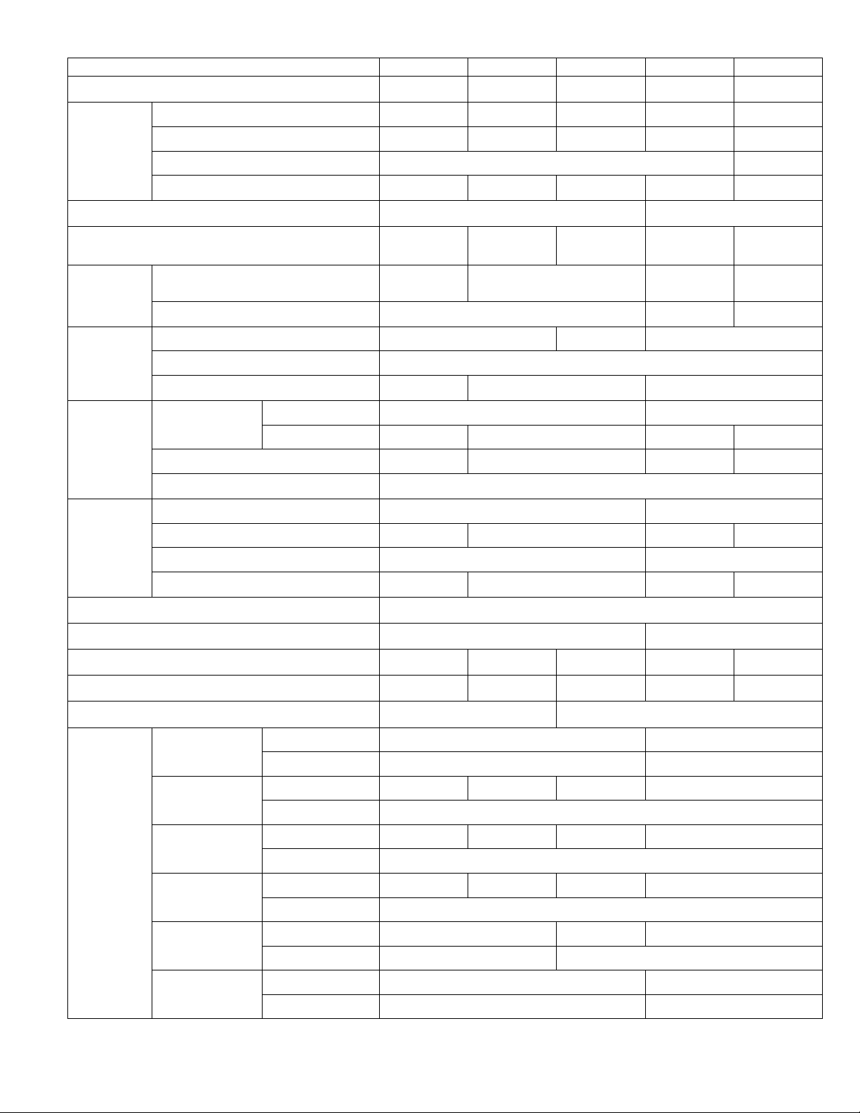
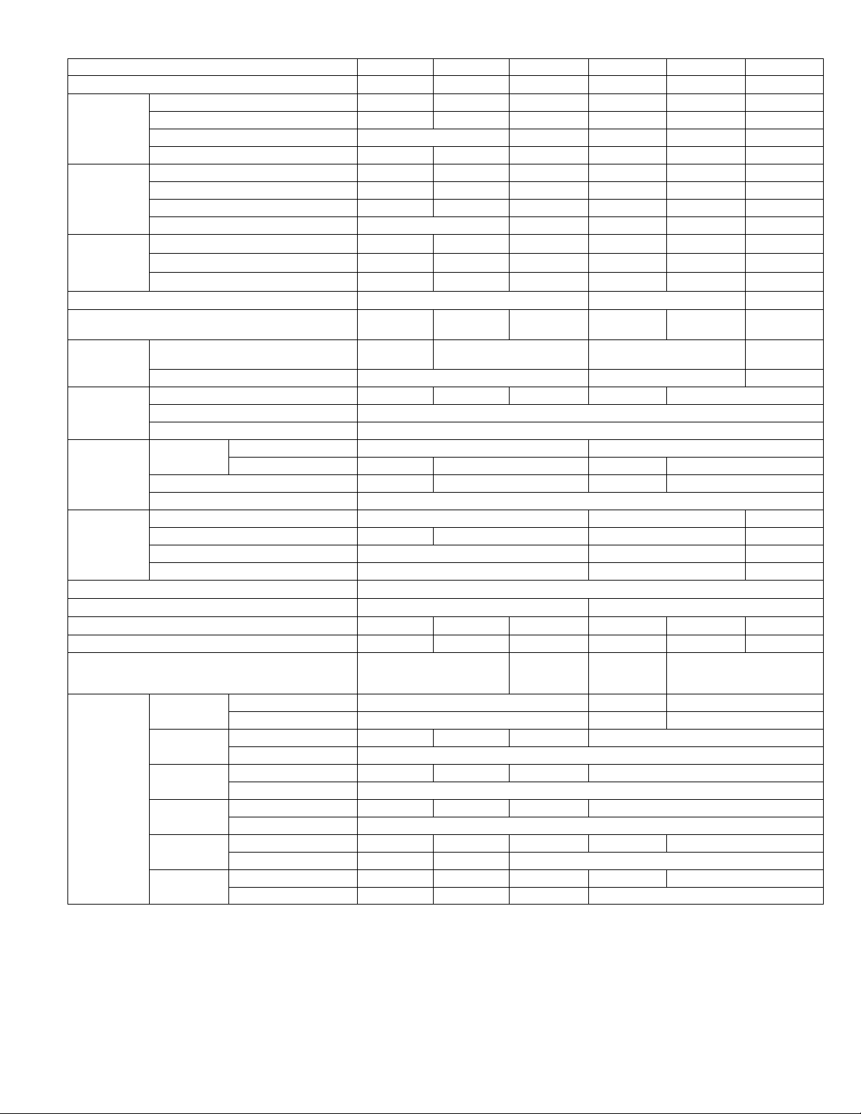
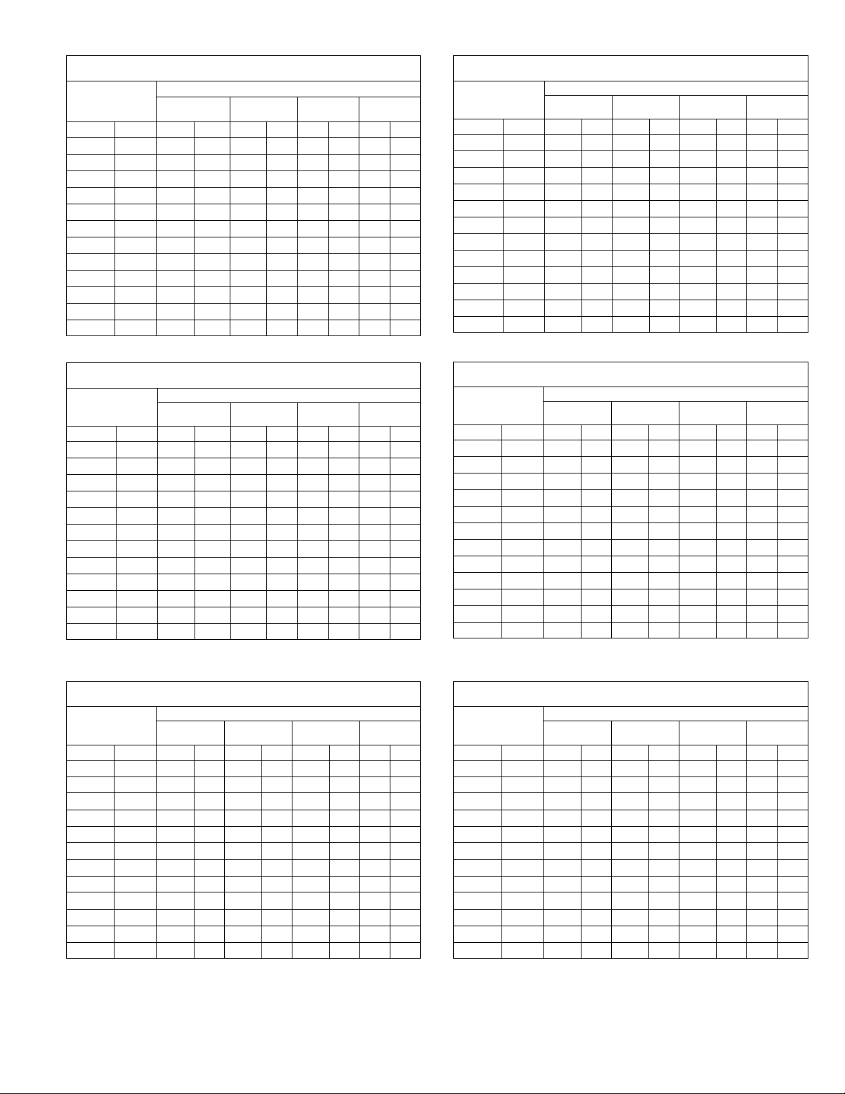
SPECIFICATIONS CHA16
Certified
g
Ratings
Coil
Net face area
Condenser
Condenser
ECH16R-5
ECH16R-7
ECH16R-10
Electric
g
Ratings
Model No. CHA16Ć024 CHA16Ć030 CHA16-036 CHA16-048 CHA16-060
Nominal Tonnage 2 2-1/2 3 4 5
Cooling capacity - Btuh (kW) 22,200 (6.5) 27,600 (8.1) 35,200 (10.3) 45,000 (13.2) 57,000 (16.5)
LARI
Certified
Cooling
Ratin
*Sound Rating Number (db) 80 82
Total unit watts 2550 3210 4045 4890 6065
SEER (Btuh/Watts) 10.0 10.25
s
EER (Btuh/Watts) 8.7 8.6 8.7 9.2 9.4
Refrigerant Charge (HCFC-22)
Blower wheel nominal
Evaporator
Blower
Evaporator
Coil
Condenser
Coil
Condenser
Fan
Condensate drain size mpt - in. (mm) 3/4 (19)
No. & size of cleanable polyurethane filters - in. (mm) (1) 16 x 25 x 1 (406 x 635 x 25) (1) 20 x 25 x 1 (508 x 635 x 25)
diameter x width in. (mm)
Motor horsepower (W) 1/3 (249) 1/2 (373) 3/4 (560)
Net face area - ft.2 (m2) 3.2 (0.30) 4.1 (0.38) 5.8 (0.54)
Tube diameter - in. (mm) & No. of rows 3/8 (9.5) - 2
Fins per inch (m) 15 (591) 17 (669) 15 (591)
Net face area
ft.2 (m2)
Tube diameter - in. (mm) & No. of rows 3/8 (9.5) - 1 3/8 (9.5) - 2 3/8 (9.5) - 1.4 3/8 (9.5) - 2
Fins per inch (m) 20 (787)
Diameter - in. (mm) & No. of blades 20 (508) - 4 24 (610) - 4
Air volume - cfm (L/s) 2400 (1135) 2200 (1040) 4000 (1890) 3600 (1700)
Motor horsepower (W) 1/6 (124) 1/4 (187)
Motor watts 230 220 340 330
Outer coil 8.6 (0.80) 14.3 (1.33)
Inner coil - - - - 8.4 (0.78) 5.9 (0.55) 13.8 (1.28)
3 lbs. 3 oz.
(1.45 kg)
9 x 8
(229 x 203)
4 lbs. 6 ozs.
(1.98 kg)
10 x 7 (254 x 178)
4 lbs. 13 ozs.
(2.18 kg)
5 lbs. 8 oz.
(2.49 kg)
10 x 8
(254 x 203)
7 lbs. 7 oz.
(3.37 kg)
11-1/2 x 9
(292 x 229)
Net weight of basic unit - lbs. (kg) 300 (136) 331 (150) 320 (145) 438 (199) 473 (215)
Shipping weight of basic unit - lbs. (kg) 1 package 385 (175) 413 (187) 407 (185) 547 (248) 582 (264)
Electrical characteristics - (60hz) 208/230v - 1 phase 208/230v - 1 ph, 208/230v, 460v or 575v - 3 ph
ECH16R-5
ECH16-5
ECH16R-7
ECH16-7
s
ECH16R-10
ECH16-10
ECH16-15
ECH16-20
ECH16-25
Optional
Electric
Heat
Ratin
*Sound Rating Number in accordance with test conditions included in ARI Standard 270.
LRated in accordance with ARI Standard 210/240 and DOE 95_F (35_F) outdoor air temperature and 80_F (27_C) db/67_F (19_C) wb entering evaporator coil air.
lAnnual Fuel Utilization Efficiency based on DOE test procedures and FTC labeling regulations.
Output - Btuh (kW) 19,000 (5.6) - - - -
lA.F.U.E. 99.0% - - - -
Output - Btuh (kW) 26,000 (7.6) 27,000 (7.9) 26,000 (7.6) 27,000 (7.9)
lA.F.U.E. 99.0%
Output - Btuh (kW) 36,000 (10.5) 37,000 (10.8) 36,000 (10.5) 37,000 (10.8)
lA.F.U.E. 99.0%
Output - Btuh (kW) 53,000 (15.5) 54,000 (15.8) 53,000 (15.5) 54,000 (15.8)
lA.F.U.E. 99.0%
Output - Btuh (kW) - - - - 70,000 (20.5) 71,000 (20.8)
lA.F.U.E. - - - - 99.0%
Output - Btuh (kW) - - - - 88,000 (25.8)
lA.F.U.E. - - - - 99.0%
Page 3
Page 4
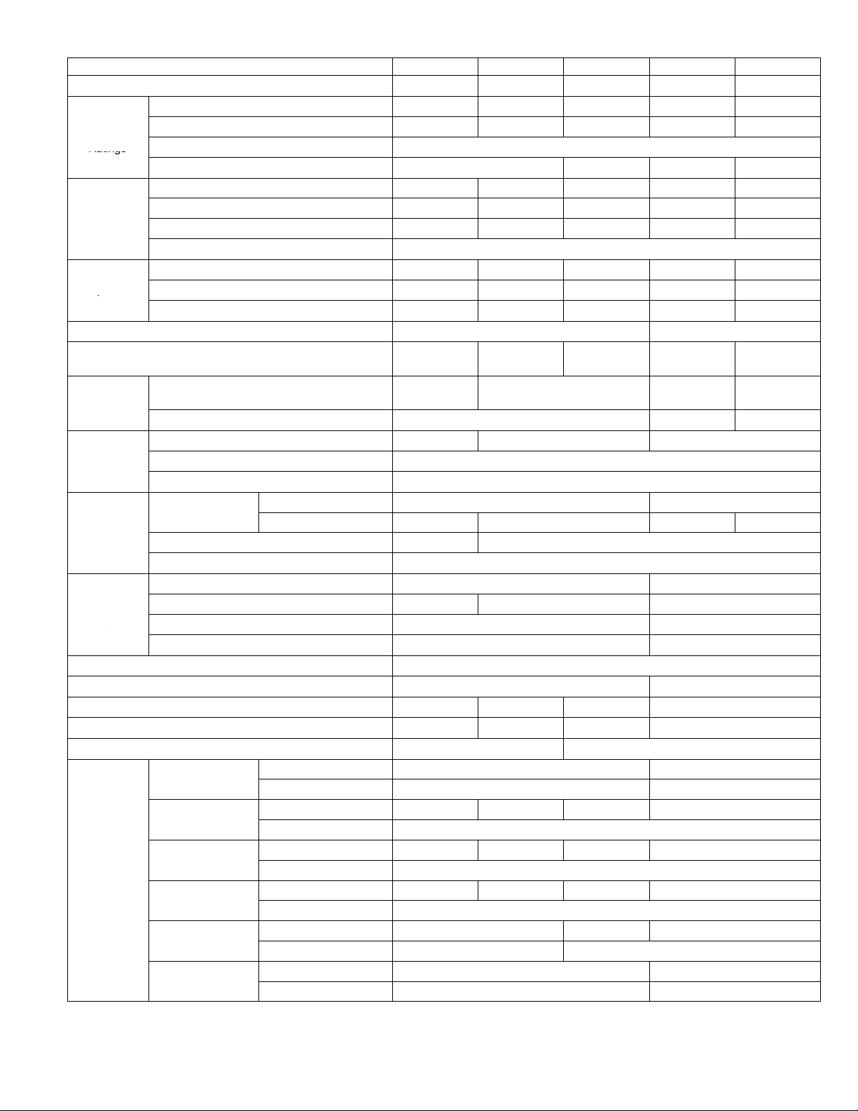
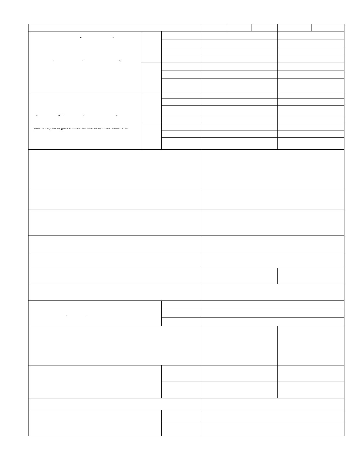
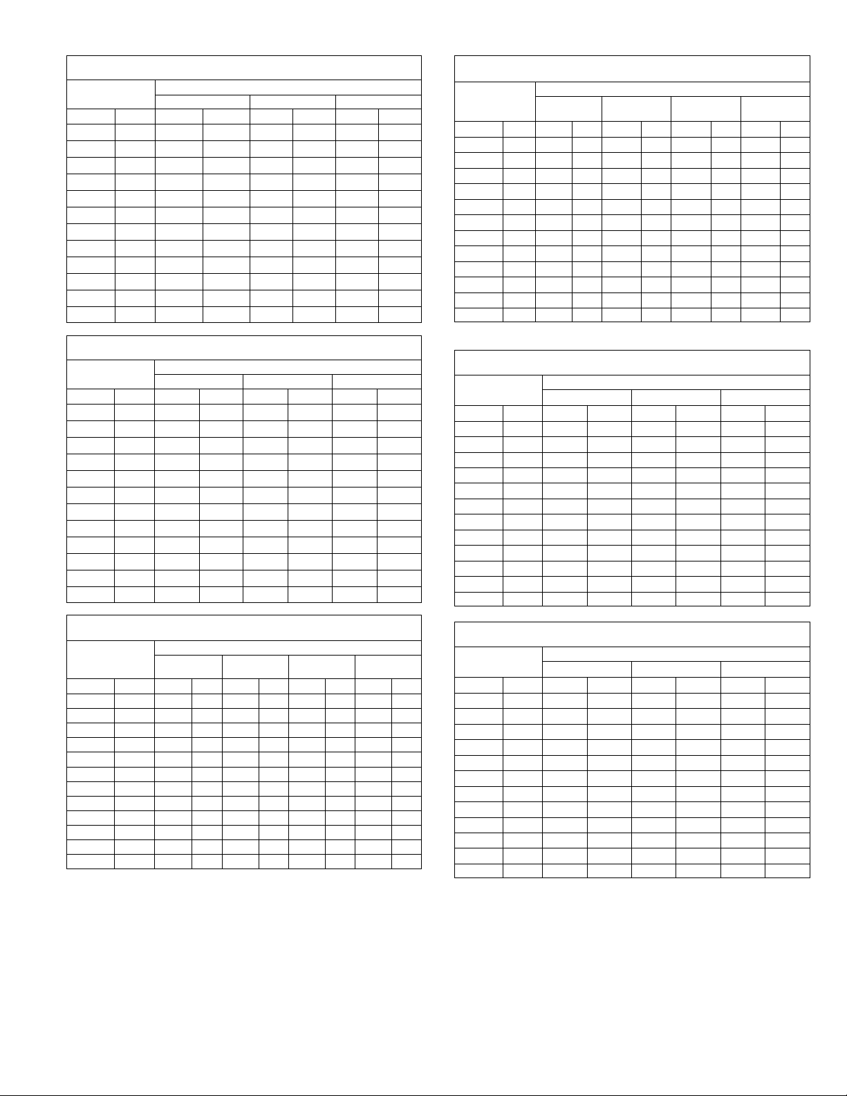
SPECIFICATIONS CHP16
C
Ratings
p
Temperature
Rati
LARI L
p
Coil
Net face area
Outdoor
C
Fan
ECH16R-5
ECH16R-7
ECH16R-10
Electric
Rati
Model No. CHP16Ć024 CHP16Ć030 CHP16-036 CHP16-048 CHP16-060
Nominal Tonnage 2 2-1/2 3 4 5
Cooling capacity - Btuh (kW) 23,800 (7.0) 29,000 (8.5) 34,600 (10.1) 46,500 (13.6) 55,000 (16.1)
LARI
ooling
Ratings
LARI High
Te m
erature
Heating
ngs
Temperature
Heating Ratings
*Sound Rating Number (db) 80 82
Refrigerant Charge (HCFC-22)
Indoor Coil
Blower
Indoor
Coil
Outdoor
Coil
Outdoor
oil
Fan
Condensate drain size mpt - in. (mm) 3/4 (19)
No. & size of cleanable polyurethane filters - in. (mm) (1) 16 x 25 x 1 (406 x 635 x 25) ( 1) 20 x 25 x 1 (508 x 635 x 25)
Net weight of basic unit - lbs. (kg) 332 (151) 340 (154) 354 (161) 535 (243)
Shipping weight of basic unit - lbs. (kg) 1 package 417 (187) 426 (193) 436 (198) 610 (277)
Electrical characteristics - (60hz) 208/230v - 1 phase 208/230v - 1 ph, 208/230v or 460v - 3 ph
Optional
Electric
Heat
ngs
*Sound Rating Number in accordance with test conditions included in ARI Standard 270.
LRated in accordance with ARI Standard 210/240;
Cooling Ratings - 95_F (35_F) outdoor air temperature and 80_F (27_C) db/67_F (19_C) wb entering indoor coil air
High Temperature Heating Ratings - 47 _F (8_C) db/43_F (6_C) wb outdoor air temperature and 70_F (21_C) entering indoor coil air
Low Temperature Heating Ratings - 17_F (-8_C) db/15_F (-9_C) wb outdoor air temperature and 70_F (21_C) entering indoor coil air.
Total unit watts 2615 3185 3870 4915 6225
SEER (Btuh/Watts) 10.0
EER (Btuh/Watts) 9.1 8.6 9.5 8.8
Total capacity - Btuh (kW) 23,800 (7.0) 29,400 (8.6) 35,800 (10.5) 49,500 (14.5) 57,500 (16.8)
Total unit watts 2235 2780 3430 4605 5765
C.O.P. (Coefficient of Performance) 3.12 3.10 3.06 3.14 2.94
HSPF - Region IV (Region V) 6.6 (5.9)
Total capacity - Btuh (kW) 12,800 (3.7) 17,000 (5.0) 22,800 (6.7) 28,000 (8.2) 33,600 (9.8)
ow
Total unit watts 1855 2330 3182 3800 5045
C.O.P. (Coefficient of Performance) 2.02 2.14 2.10 2.16 1.98
Blower wheel nominal diameter x width in. (mm)
5 lbs. 10 oz.
(2.55 kg)
9 x 8
(229 x 203)
6 lbs. 0 oz.
(2.72 kg)
10 x 7 (254 x 178)
7 lbs. 0 oz..
(3.18 kg)
10 lbs. 12 oz.
(4.88 kg)
10 x 8
(254 x 203)
Motor horsepower (W) 1/3 (249) 1/2 (373) 3/4 (560)
Net face area - sq. ft. (m2) 3.2 (0.30) 4.1 (0.38) 5.8 (0.54)
Tube diameter - in. (mm) & No. of rows 3/8 (9.5) - 3
Fins per inch (m) 15 (591)
Net face area
sq. ft. (m2)
Outer coil 8.6 (0.80) 14.3 (1.33)
Inner coil 5.3 (0.49) 8.3 (0.77) 9.9 (0.92) 13.8 (1.28)
Tube diameter - in. (mm) & No. of rows 3/8 (9.5) - 1.6 3/8 (9.5) - 2
Fins per inch (m) 20 (787)
Diameter - in. (mm) & No. of blades 20 (508) - 4 24 (610) - 4
Air volume - cfm (L/s) 2350 (1110) 2200 (1040) 3600 (1700)
Motor horsepower (W) 1/6 (124) 1/4 (187)
Motor watts 220 340
ECH16R-5
ECH16-5
ECH16R-7
ECH16-7
ECH16R-10
ECH16-10
Output - Btuh (kW) 19,000 (5.6) - - - -
lA.F.U.E. 99.0% - - - -
Output - Btuh (kW) 26,000 (7.6) 27,000 (7.9) 26,000 (7.6) 27,000 (7.9)
lA.F.U.E. 99.0%
Output - Btuh (kW) 36,000 (10.5) 37,000 (10.8) 36,000 (10.5) 37,000 (10.8)
lA.F.U.E. 99.0%
Output - Btuh (kW) 53,000 (15.5) 54,000 (15.8) 53,000 (15.5) 54,000 (15.8)
ECH16-15
lA.F.U.E. 99.0%
Output - Btuh (kW) - - - - 70,000 (20.5) 71,000 (20.8)
ECH16-20
lA.F.U.E. - - - - 99.0%
Output - Btuh (kW) - - - - 88,000 (25.7)
ECH16-25
lA.F.U.E. - - - - 99.0%
10 lbs. 5 oz.
(4.68 kg)
11-1/2 x 8
(292 x 203)
Page 4
Page 5
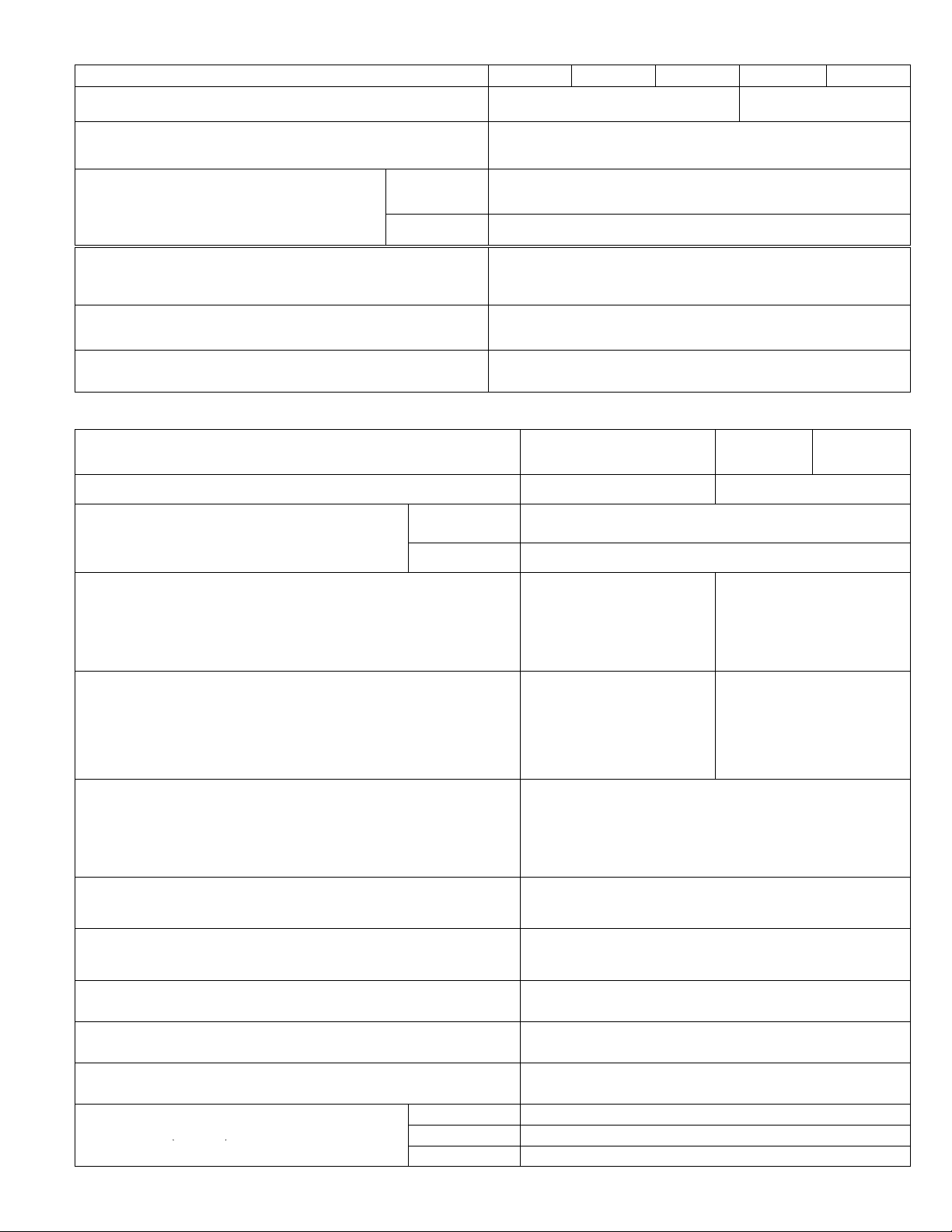
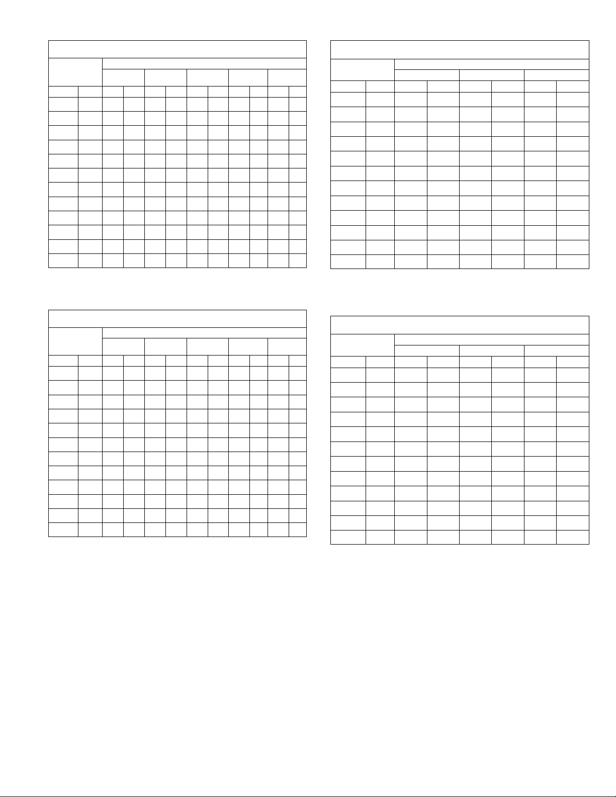
SPECIFICATIONS CHP20
Cooli
g
Ratings
LARI Certified
High
p
Temperature
Bl
Coil
Net face area
Outdoor
Outdoor
ECH16RĆ5
ECH16RĆ7
Electric Heat
ECH16RĆ10
Model No
ECH16Ć15
ECH16Ć20
ECH16Ć25
Model No. CHP20Ć024 CHP20Ć030 CHP20Ć036 CHP20Ć042 CHP20Ć048 CHP20Ć060
Nominal Tonnage 2 2-1/2 3 3-1/2 4 5
Cooling Capacity Ċ Btuh (kW) 24,000 (7.0) 30,200 (8.8) 33,600 (9.8) 43,000 (12.6) 46,500 (13.6) 59,000 (17.3)
LARI
Ratin
High
Temperature
Heating Ratings
LARI Certified
Low
Te m
erature
Heating Ratings
*Sound Rating Number (db) 80 82 84
Refrigerant Charge (HCFCĆ22)
Indoor Coil
ower
Indoor
Outdoor
Coil
Outdoor
Coil Fan
Condensate drain size mpt Ċ in. (mm) 3/4 (19)
No. & size of cleanable polyurethane filters - in. (mm) (1) 16 x 25 x 1 (406 x 635 x 25) (1) 20 x 25 x 1 (508 x 635 x 25)
Net weight of basic unit Ċ lbs. (kg) 305 (138) 355 (161) 355 (161) 455 (206) 535 (243) 535 (243)
Shipping weight of basic unit Ċ lbs. (kg) (1 Pkg.) 390 (177) 419 (190) 419 (190) 525 (238) 610 (277) 610 (277)
Electrical characteristics (60 hz) 208/230v-1ph
Model No.
and
Ratings
*Sound Rating Number in accordance with test conditions included in ARI Standard 270.
lAnnual Fuel Utilization Efficiency based on DOE test procedures and FTC labeling regulations.
LCertified in accordance with the USE certification program, which is based on ARI standard 210/240.
Cooling RatingsĊ 95_F (35_C) outdoor air temperature and 80_F (27_C) db/67_F (19.5_C) wb entering indoor coil air.
High Temperature Heating RatingsĊ 47_F (8_C) db/43_F (6_C) wb outdoor air temperature and 70_F (21_C) entering indoor coil air.
Low Temperature Heating RatingsĊ 17_F (-8_C) db/15_F (-9_C) wb outdoor air temperature and 70_F (21_C) entering indoor coil air.
Total unit watts 2555 3145 3535 4105 4875 6325
ng
SEER (Btuh/Watts) 11. 0 11 .0 5 12.05 11. 00 11.05
s
EER (Btuh/Watts) 9.4 9.6 9.5 10.5 9.5 9.4
Total Capacity Ċ Btuh (kW) 24,200 (7.1) 29,800 (8.7) 34,200 (10.0) 41,500 (12.2) 48,500 (14.2) 62,500 (18.3)
Total unit watts 2245 2800 3000 3880 4695 6180
C.O.P 3.16 3.12 3.34 3.20 3.04 2.98
HSPF Ċ Region IV (Region V) 6.60 (5.90) 7.35 (5.70) 7.15 (6.30) 7.55 (6.70) 6.85 (6.05)
Total Capacity Ċ Btuh (kW) 14,800 (4.3) 18,600 (5.4) 21,400 (6.3) 26,200 (7.7) 31,600 (9.3) 38,600 (11.3)
Total unit watts 2085 2595 2725 3515 4225 5425
C.O.P 2.06 2.10 2.30 2.26 2.20 2.10
Blower wheel nominal diameter x width in. (mm)
5 lbs. 0 oz.
(2.27 kg)
9 x 8
(229 x 203)
6 lbs. 8 oz.
(2.95 kg)
6 lbs. 7 oz.
(2.92 kg)
9 lbs. 12 oz.
(4.42 kg)
10 x 7 (254 x 178) 10 x 8 (254 x 203)
10 lbs. 8 oz.
(4.76 kg)
Motor output Ċ hp (W) 1/3 (249) 1/2 (373) 3/4 (560)
Net face area Ċ sq. ft. (m2) 3.2 (0.30) 4.1 (0.38) 4.1 (0.38) 5.8 (0.54) 5.8 (0.54)
Tube diameter - in. (mm) & No. of rows 3/8 (9.5) Ċ 3
Fins per inch (m) 15 (591)
Net face area
Ċ sq. ft. (m2)
Outer coil 8.6 (0.80) 14.3 (1.33)
Inner coil 5.3 (0.49) 8.3 (0.77) 9.9 (1.28) 13.8 (1.28)
Tube diameter - in. (mm) & no. of rows 3/8 (9.5) - 1.6 3/8 (9.5) Ċ 2 3/8 (9.5) - 1.7 3/8 (9.5) Ċ 2
Fins per inch (m) 20 (787)
Diameter Ċ in. (mm) & No. of blades 20 (508) Ċ 4 24 (610) Ċ 4 24 (610) - 3
Air Volume Ċ cfm (L/s) 2350 (1110) 2200 (1040) 3600 (1700) 4000 (1890)
Motor output Ċ hp (W) 1/6 (124) 1/4 (187) 1/3 (249)
Motor watts 220 340 430
208/230v-1ph
208/230v or
460v - 3ph
208/230v-1ph
208/230v-1ph
208/230v or 460v - 3ph
Output Ċ Btuh (kW) 19,000 (5.6) Ć Ć Ć Ć Ć Ć Ć Ć
lA.F.U.E. 99.0% Ć Ć Ć Ć Ć Ć Ć Ć
Output Ċ Btuh (kW) 26,000 (7.6) 27,000 (7.9) 26,000 (7.6) 27,000 (7.9)
lA.F.U.E. 99.0%
Output Ċ Btuh (kW) 36,000 (10.5) 37,000 (10.8) 36,000 (10.5) 37,000 (10.8)
lA.F.U.E. 99.0%
.
ECH16RĆ7
ECH16Ć7
ECH16RĆ10
ECH16Ć10
Output Ċ Btuh (kW) 53,000 (15.6) 54,000 (15.8) 53,000 (15.6) 54,000 (15.8)
lA.F.U.E. 99.0%
Output Ċ Btuh (kW) Ć Ć Ć Ć Ć Ć Ć Ć 70,000 (20.5) 71,000 (20.8) 71,000 (20.8)
lA.F.U.E. Ć Ć Ć Ć Ć Ć Ć Ć 99.0%
Output Ċ Btuh (kW) Ć Ć Ć Ć Ć Ć Ć Ć Ć Ć Ć Ć 88,000 (25.7) 88,000 (25.8)
lA.F.U.E. Ć Ć Ć Ć Ć Ć Ć Ć Ć Ć Ć Ć 99.0%
10 lbs. 5 oz.
(4.68 kg)
11 x 8
(279 x 203)
Page 5
Page 6
Model No. Ć024 Ć030 -036 -048 -060
yp
p
y
lated air dampers with pressure operated gravity
US
p, g
p
lizes filter furnished with unit, filter rack will accept
hood
ith cl
ly in cabinet, combination outdoor air and recircu
US
yg,p j
sensor, adjustable outdoor air enthalpy control. 1 in
(25 mm) fiberglass filter furnished, filter rack will
hood with alumi
filt
kit
()
p
y
damper assembly replaces blower access panel, manually
Economizer with Gravity Exhaust Dampers
(Down-Flow) Ċ Installs directly in cabinet, recircuĆ
lated air dam
exhaust damper, formed, gasketed damper blades,
nylon bearings, 24v damper motor has adjustable
minimum position switch, electronic discharge air
sensor, adjustable outdoor air enthalpy control. UtiĆ
lizes filter furnished with unit, filter rack will acce
up to 2 in. (51 mm) filter. Removable exhaust air
and outdoor air intake hood w
aluminum mesh filter. Choice of economizer conĆ
trols.
Economizer Dampers (Horizontal) Ċ Installs directĆ
lated air damper, formed, gasketed damper blades,
nylon bearings, 24v damper motor has adjustable
minimum position switch, electronic discharge air
(25 mm) fiberglass filter furnished, filter rack will
accept up to 2 in. (51 mm) filter, outdoor air intake
mizer controls.
Electric Heat Ċ Field installed, helix wound nichrome elements, time delay for eleĆ
ment staging, individual element limit controls, wiring harness, may be twoĆstage
controlled.
ECH16R - Supplemental thermal cutoff safety fuses and thermal
ECH16 - Supplemental secondary limits, heating control relay,
Electric Heat Single Point Power Source Sub-Fuse Box Ċ Use with ECH16R
electric heaters, use in conjunction with ECH16 fuse box for single point power
source applications, installs internal to unit, fuses furnished, constructed of galvaĆ
nized steel with prepunched mounting holes
Unit Single Point Power Source Sub Fuse Box Ċ Installs internal to unit, proĆ
vides sub-fusing to the unit, used in conjunction with ECH16 or ECH16R for single
point power source applications, fuses furnished, constructed of galvanized steel
with prepunched mounting holes and electrical inlet and outlet holes, hinged box
cover
Enthalpy Control, Differential Ċ Used in conjunction with outdoor air enthalpy
control. Determines and selects which air has the lowest enthalpy. Return air enĆ
thalpy sensor field installs in economizer damper section
Gravity Exhaust Dampers Ċ For use with EMDH16. Pressure operated assembly
field installs in the return air duct adjacent to the economizer assembly. Includes
bird screen. - Net Weight
Horizontal Filter Kit (Canada Only) Ċ For horizontal applications, painted steel
cabinet with filter access, disposable, pleated fiber filter furnished, number and
size of filter - Net Weight
Low Ambient Control Kit Ċ Units operate down to 30°F (-1°C) outdoor air temperĆ
ature in cooling mode without any additional controls. A Low Ambient Kit can be
field installed, enabling unit to operate properly down to 0°F (Ć17.7°C).
Roof Curb Power Entry Kit Ċ Allows power entry through
roof mounting frame, knockouts provided in roof frame,
contains 40 in. (1016 mm) armored conduit and installation
hardware, two kits are required, one for low voltage and one
for high voltage. See Dimension Drawing
Roof Mounting Frame Ċ Nailer strip furnished, mates to unit, U.S. National RoofĆ
ing Contractors Approved, shipped knocked down. RMF16-41 may be used on
all sizes, with a slight unit overhang on CHP16-048 and CHP16-060 units - Net
Weight
NOTE (US Only) Ċ Sound Reduction Plate must be ordered separately for field
installation.
Outdoor Air Damper Section Ċ For downĆflow applications,
dam
adjustable, 0 to 25% (fixed) outdoor air, outdoor air hood with
cleanable filter included, number and size of filter - Net Weight
Outdoor Air Damper Section Ċ For horizontal applications, installs in return air
duct adjacent to unit, manually adjustable (fixed) outdoor air - Net Weight
Outdoor Thermostat Kit Ċ Used to lock out some of the
electric heating elements on indoor units where two stage
control is applicable. Outdoor thermostat maintains the
heating load on the low power input as long as possible
before allowing the full power load to come on line
Indoor filter is not furnished with economizer. REMD16 utilizes existing filter furnished with 16 unit.
ers with pressure operated gravit
eanable
num mesh
relay sequencer.
fuse block, thermal relay sequencer (20-25 kW
208/230v) and galvanized steel control box.
er assembly replaces blower access panel, manuall
er. Choice of econoĆ
OPTIONAL ACCESSORIES CHA/CHP16
3 position REMD16-41 - 48 lbs. (22 kg) REMD16-65 - 66 lbs. (30 kg)
US
Only
t
Canada
Only
Ć
Ć
Only
Canada
Ć
Only
Fully Modulating REMD16M-41 - 48 lbs. (22 kg) REMD16M-65 - 66 lbs. (30 kg)
Indoor Filter (1) 16 x 25 x 1 (406 x 635 x 25) (1) 20 x 25 x 1 (508 x 635 x 25)
Outdoor Filter (1) 14 x 25 x 1 (356 x 635 x 25) (1) 18 x 25 x 1 (457 x 635 x 25)
Fully Modulating REMD16M-41S - 85 lbs. (39 kg) REMD16M-65S- 105 lbs. (48 kg)
Indoor Filter (1) 16 x 25 x 1 (406 x 635 x 25) (1) 20 x 25 x 1 (508 x 635 x 25)
Outdoor Filter (1) 19-3/8 x 15-3/4 x 1
3 position EMDH16-41 110 lbs. (50 kg) EMDH16-65 - 130 lbs. (59 kg)
Fully Modulating EMDH16M-41 - 110 lbs. (50 kg) EMDH16M-65 - 130 lbs. (59 kg)
Indoor Filter (1) 20 x 24 x 1 (508 x 610 x 25)
Outdoor Filter (1) 8 x 24 x 1 (203 x 610 x 25) (1) 8 x 28 x 1 (203 x 711 x 25)
Fully Modulating EMDH16M-41S - 70 lbs. (32 kg) EMDH16M-65S - 86 lbs. (39 kg)
Indoor Filter (1) 20 x 20 x 1 (508 x 508 x 25) (1) 20 x 25 x 1 (508 x 635 x 25)
Outdoor Filter
1/2 in. (13 mm) 18H70
1 in. (26 mm) 18H71
1-1/2 in. (39 mm) 18H72
US Only
Canada Only
Thermostat Kit LB-29740BA (56A87)
Mounting Box M-1595 (31461) / BM-10260 (33A09) Canada Only
(1) 16-1/2 x 21-3/4 x 1
HF16-46S - 18 lbs. (8 kg)
RMF16-41 - 75 lbs. (35 kg) 97G59
Plate (order separately) (73H80)
OAD16-41 - 12 lbs. (5 kg)
OAD16-41S - 10 lbs. (5 kg)
Page 6
(419 x 552 x 25)
See Electric Heat Data Tables
See Electric Heat Data Tables
See Electric Heat Data Tables
GEDH16-65 - 4 lbs. (2 kg)
(1) 20 x 20 x 2 in.
(508 x 508 x 51 mm)
CHP16 LB-57113BM (27J00)
CHA16 LB-57113BC (24H77)
(1) 5 x 17 x 1 in.
(127 x 432 x 25 mm)
(1) 14 x 6 x 1 in.
(356 x 152 x 25 mm)
OAD3-46/65 - 8 lbs. (4 kg)
(1) 19-7/8 x 22-3/4 x 1
(505 x 578 x 25)
(1) 16 x 25 x 1 (406 x 635 x 25)
(1) 14 x 25 x1 (356 x 635 x 1)
(1) 22-1/2 x 25-1/4 x 1
(571 x 641 x 25)
54G44
HF16-65S - 21 lbs. (10 kg)
(1) 20 x 25 x 2 in.
(508 x 635 x 51 mm)
RMF16-41 - 75 lbs. (35 kg)
OAD16-65 - 12 lbs. (5 kg)
OAD16-65S - 16 lbs. (7 kg)
97G59
Plate (order separately)
(73H80)
RMF16-65 - 86 lbs.
(39 kg) 97G60
Plate (order separately)
(73H82)
(1) 8 x 17 x 1 in.
(203 x 432 x 25 mm)
(1) 18 x 6 x 1 in.
(457 x 152 x 25 mm)
Page 7
OPTIONAL ACCESSORIES CHA/CHP16 Cont.
nished, interior transition (even air flow), internally
transition (even air flow), internally sealed (prevents recirĆ
kit
()
Model No. Ć024 Ć030 -036 -048 -060
Coil Guards Ċ PVC coated steel wire guards to protect outdoor coil.
Compressor Monitor (Canada Only) Ċ NonĆadjustable switch (low ambiĆ
ent cutĆout) prevents compressor operation when outdoor temperature is
below 35°F (2°C).
Diffusers Ċ Aluminum grilles, large center grille, inĆ
sulated diffuser box with flanges, hanging rings furĆ
nished, interior transition (even air flow), internally
sealed (prevents recirculation), adapts to TĆbar ceilĆ
ing grids or plaster ceilings - Net Weight
Timed Off Control Ċ Prevents compressor shortĆcycling and allows time
for suction and discharge pressure to equalize, permitting the compressor
to start in an unloaded condition. Automatic reset control provides a time
delay between compressor shutoff and startĆup.
Transitions (Supply and Return) Ċ Used with diffusers, installs in roof
mounting frame, galvanized steel construction, flanges furnished for duct
connection, fully insulated - Net Weight
Unit Stand-Off Mounting Kit Ċ Elevates horizontal application units
above mounting surface. Includes six high impact polystyrene standĆoff
mounts. See dimension drawings.
StepĆDown -
double deflecĆ
tion louvers
Flush - fixed
blade louvers
OPTIONAL ACCESSORIES CHP20
Model No.
Coil Guards Ċ PVC coated steel wire guards to protect outdoor coil.
Diffusers Ċ Aluminum grilles, large center grille, insulated
diffuser box with flanges, hanging rings furnished, interior
transition (even air flow), internally sealed (prevents recirĆ
culation), adapts to TĆbar ceiling grids or plaster ceilings Net Weight
Economizer with Gravity Exhaust Dampers (Down-Flow) Ċ Installs directly in
cabinet, recirculated air dampers with pressure operated gravity exhaust dampĆ
er, formed, gasketed damper blades, nylon bearings, 3 position or fully moduĆ
lating 24v damper motor has adjustable minimum position switch, electronic
discharge air sensor, adjustable outdoor air enthalpy control. Utilizes filter furĆ
nished with unit, filter rack will accept up to 2 in. (51 mm) filter. Removable
exhaust air hood and outdoor air intake hood with aluminum mesh filter. Choice
of economizer controls. Model No. - Net Weight - No. & size of filter, in. (mm)
Economizer Dampers (Horizontal) Ċ Installs directly in cabinet, combination outĆ
door air and recirculated air damper, formed, gasketed damper blades, nylon
bearings, 3 position or fully modulating 24v damper motor has adjustable miniĆ
mum position switch, electronic discharge air sensor, adjustable outdoor air enĆ
thalpy control. 1 in (25 mm) fiberglass filter furnished, filter rack will accept up to 2
in. (51 mm) filter, outdoor air intake hood with aluminum mesh filter. Choice of
economizer controls. Model No. - Net Weight - No. & size of filter, in. (mm)
Electric Heat Ċ Field installed, helix wound nichrome elements, time delay for eleĆ
ment staging, individual element limit controls, wiring harness, may be twoĆstage
controlled.
ECH16R - Supplemental thermal cutoff safety fuses and thermal
ECH16 - Supplemental secondary limits, heating control relay,
Electric Heat Single Point Power Source Sub-Fuse Box Ċ Use with ECH16R elecĆ
tric heaters, use in conjunction with ECH16 fuse box for single point power source
applications, installs internal to unit, fuses furnished, constructed of galvanized steel
with prepunched mounting holes
Unit Single Point Power Source Sub Fuse Box Ċ Installs internal to unit, provides
sub-fusing to the unit, used in conjunction with ECH16 or ECH16R for single point
power source applications, fuses furnished, constructed of galvanized steel with
prepunched mounting holes and electrical inlet and outlet holes, hinged box cover
Enthalpy Control, Differential Ċ Used in conjunction with outdoor air enthalpy
control. Determines and selects which air has the lowest enthalpy. Return air enĆ
thalpy sensor field installs in economizer damper section
Gravity Exhaust Dampers Ċ For use with EMDH16. Pressure operated assembly
field installs in the return air duct adjacent to the economizer assembly. Includes
bird screen. - Net Weight
Low Ambient Control Kit - Units operate down to 30°F (-1°C) outdoor air temperaĆ
ture in cooling mode without any additional controls. A Low Ambient Kit can be field
installed, enabling unit to operate properly down to 0°F (Ć17.7°C).
Roof Curb Power Entry Kit Ċ Allows power entry through
roof mounting frame, knockouts provided in roof frame,
contains 40 in. (1016 mm) armored conduit and installaĆ
tion hardware, two kits are required, one for low voltage
and one for high voltage. See Dimension Drawing
relay sequencer.
fuse block, thermal relay sequencer (20-25 kW
208/230v) and galvanized steel control box.
StepĆDown -
double deflecĆ
tion louvers
Flush - fixed
blade louvers
1/2 in. (13 mm) 18H70
1 in. (26 mm) 18H71
1-1/2 in. (39 mm) 18H72
LB-82199CF (47J23)
2 guards per order
T6-1469 (45F08)
RTD9-65 - 67 lbs. (30 kg)
FD9-65 Ć 37 lbs.(17 kg)
LB-50709BK (47J27)
SRT16 - 20 lbs. (9 kg)
38H18
CHP20-024
CHP20-030
CHP20-036
LB-82199CF (47J23)
2 guards per order
RTD9-65 - 67 lbs. (30 kg)
FD9-65 Ć 37 lbs.(17 kg)
REMD16-41 - 48 lbs. (22 kg)
REMD16M-41 - 48 lbs. (22 kg)
EMDH16-41 - 110 lbs. (50 kg)
EMDH16M-41 - 110 lbs. (50 kg)
3 Position:
Modulating:
Indoor: (1) 16 x 25 x 1
(406 x 635 x 25)
Outdoor : (1) 14 x 25 x 1
(356 x 635 x 25)
3 Position:
Modulating:
Indoor : (1) 20 x 24 x 1
(508 x 610 x 25)
Outdoor : (1) 8 x 24 x 1
(203 x 610 x 25)
See Electric Heat Data Tables
See Electric Heat Data Tables
See Electric Heat Data Tables
GEDH16-65 - 4 lbs. (2 kg)
LB-57113BM (27J00)
LB-82199CG (47J24)
3 guards per order
CHP20-042
CHP20-048
LB-82199CG (47J24)
3 guards per order
REMD16-65 - 66 lbs. (30 kg)
REMD16M-65 - 66 lbs. (30 kg)
EMDH16-65 - 130 lbs. (59 kg)
EMDH16M-65 - 130 lbs. (59 kg)
(1) 14 x 25 x1 (356 x 635 x 1)
54G44
3 Position:
Modulating:
Indoor: (1) 20 x 25 x 1
(508 x 635 x 25)
Outdoor : (1) 18 x 25 x 1
(457 x 635 x 25)
3 Position:
Modulating:
Indoor : (1) 16 x 25 x 1
(406 x 635 x 25) &
Outdoor : (1) 8 x 28 x 1
(203 x 711 x 25)
CHP20-060
Page 7
Page 8
OPTIONAL ACCESSORIES CHP20 Cont.
C
Condenser Coil
Evaporator
C
Condenser Coil
Evaporator
Model No. CHP20-024, -030, -036 CHP20-042, -048 CHP20-060
Roof Mounting Frame Ċ Nailer strip furnished, mates to unit, U.S. National
Roofing Contractors Approved, shipped knocked down. RMF16-41 may be
used on all sizes, with a slight unit overhang on CHP20-048 and CHP20-060
units - Net Weight. NOTE (US Only) Ċ Sound Reduction Plate must be ordered
separately for field installation.
Outdoor Air Damper Section Ċ For downĆflow applications, damper assembly reĆ
places blower access panel, manually adjustable, 0 to 25% (fixed) outdoor air, outĆ
door air hood with cleanable filter included, number and size of filter - Net Weight
Outdoor Air Damper Section Ċ For horizontal applications, installs in return
air duct adjacent to unit, manually adjustable (fixed) outdoor air - Net Weight
Outdoor Thermostat Kit Ċ Used to lock out some of the
electric heating elements on indoor units where two
stage control is applicable. Outdoor thermostat maintains
the heating load on the low power input as long as posĆ
sible before allowing the full power load to come on line
Timed Off Control Ċ Prevents compressor shortĆcycling and allows time for
suction and discharge pressure to equalize, permitting the compressor to start
in an unloaded condition. Automatic reset control provides a time delay beĆ
tween compressor shutoff and startĆup.
Transitions (Supply and Return) Ċ Used with diffusers, installs in roof mountĆ
ing frame, galvanized steel construction, flanges furnished for duct connection,
fully insulated - Net Weight
Unit Stand-Off Mounting Kit Ċ Elevates horizontal application units above
mounting surface. Includes six high impact polystyrene standĆoff mounts. See
dimension drawings.
Indoor filter is not furnished with economizer. REMD16 utilizes existing filter furnished with CHP20 unit.
Thermostat Kit LB-29740BA (56A87)
Mounting Box M-1595 (31461)
RMF16-41 - 75 lbs. (35 kg)
Plate (order separately) (73H80)
OAD16-41 - 12 lbs. (5 kg)
(1) 5 x 17 x 1 in.
(127 x 432 x 25 mm)
RMF16-41 - 75 lbs. (35 kg)
Plate (order separately) (73H80)
RMF16-65 - 86 lbs. (39 kg)
Plate (order separately) (73H82)
OAD16-65 - 12 lbs. (5 kg)
(1) 8 x 17 x 1 in.
(203 x 432 x 25 mm)
OAD3-46/65 - 8 lbs. (4 kg)
LB-50709BK (47J27)
SRT16 - 20 lbs. (9 kg)
38H18
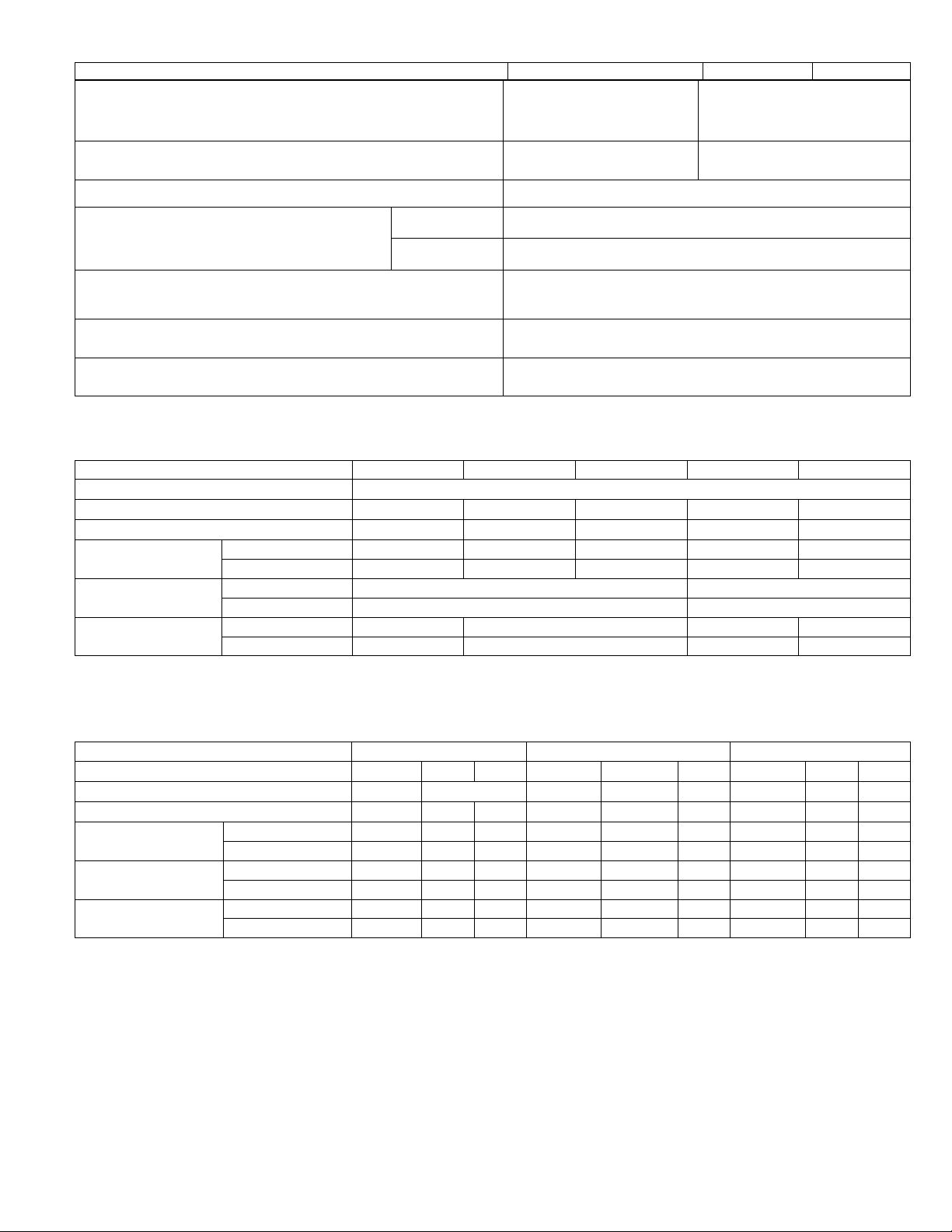
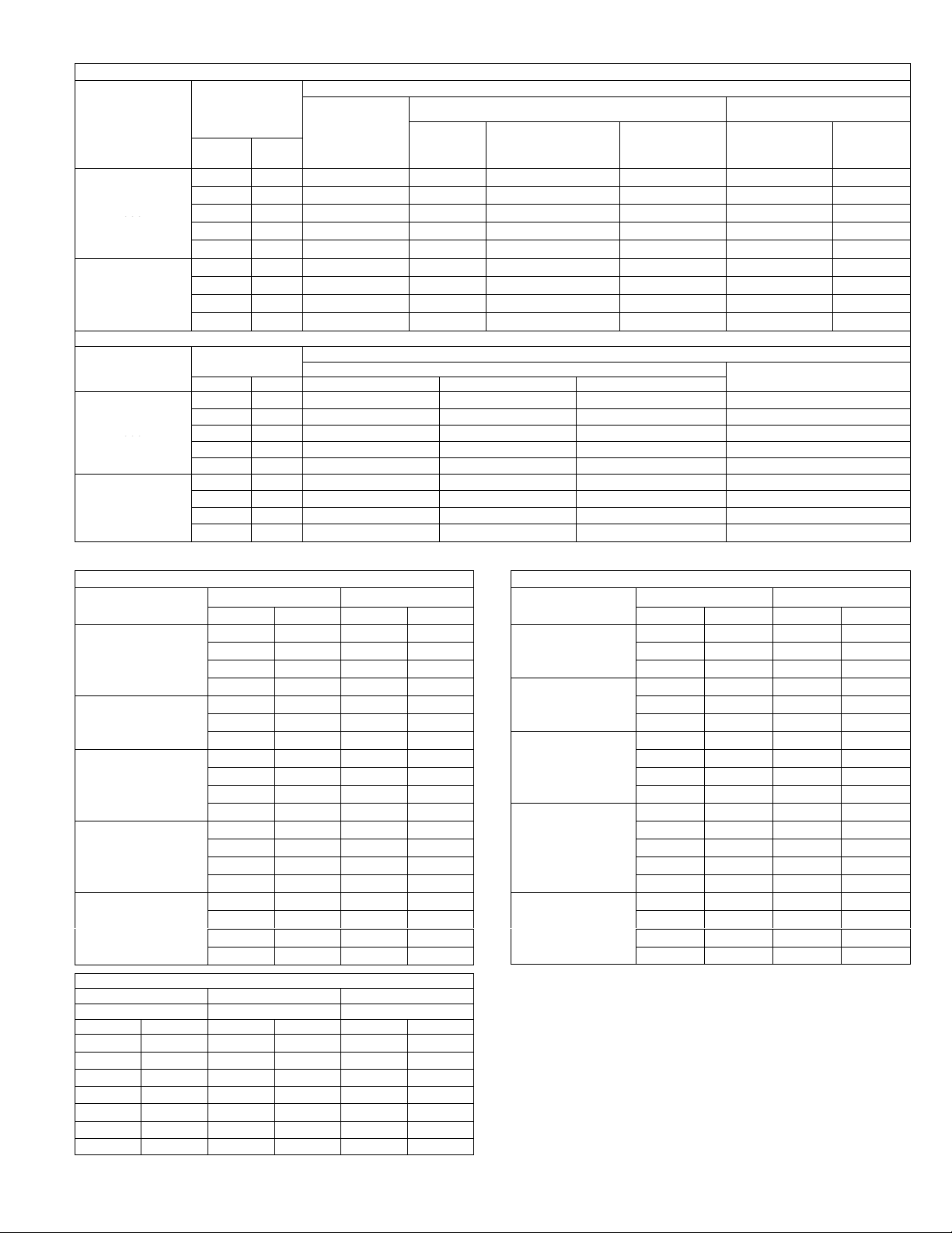
ELECTRICAL DATA CHA16
Single Phase
ModelĂNo. CHA16Ć024 CHA16Ć030 CHA16Ć036 CHA16Ć048 CHA16Ć060
LineĂvoltageĂdataĂ-Ă60Ăhz 208/230v - 1 phase
Recommended maximum fuse size (amps) 25 30 40 50 60
{Minimum Circuit Ampacity 16 21 27 34 41
ompressor
Condenser Coil
FanĂMotor
Evaporator
Blower Motor
{ReferĂtoĂNational or CanadianĂElectricalĂCodeĂmanualĂtoĂdetermineĂwire,ĂfuseĂandĂdisconnectĂsizeĂrequirements.
Where current does not exceed 100 amps, HACR type circuit breaker may be used in place of fuse (U.S. Only).
NOTEĂ-ĂExtremesĂofĂoperatingĂrangeĂareĂplusĂandĂminusĂ10%ĂofĂlineĂvoltage.
Rated load amps 10.1 13.0 17.7 21.8 26.1
Locked rotor amps 60 69.4 100.0 131.0 170
FullĂloadĂamps 1.1 2.3
LockedĂrotorĂamps 2.2 4.4
FullĂloadĂamps 2.2 3 3.9 5.2
LockedĂrotorĂamps 4.2 6.2 8.3 10
ELECTRICAL DATA CHA16
Three Phase
ModelĂNo. CHA16Ć036 CHA16Ć048 CHA16Ć060
LineĂvoltageĂdataĂ-Ă60Ăhz - 3 phase 208/230v 460v 575v 208/230v 460v 575v 208/230v 460v 575v
Recommended maximum fuse size (amps) 30 15 35 15 15 40 20 15
{Minimum Circuit Ampacity 20 11 9 23 11 10 28 14 12
ompressor
Condenser Coil
FanĂMotor
Evaporator
Blower Motor
{ReferĂtoĂNational or CanadianĂElectricalĂCodeĂmanualĂtoĂdetermineĂwire,ĂfuseĂandĂdisconnectĂsizeĂrequirements.
Where current does not exceed 100 amps, HACR type circuit breaker may be used in place of fuse (U.S. Only).
Motors are rated at 460 volts. Full load amps shown are for step-down transformer output.
NOTEĂ-ĂExtremesĂofĂoperatingĂrangeĂareĂplusĂandĂminusĂ10%ĂofĂlineĂvoltage.
Rated load amps 12.2 6.2 4.6 12.8 6.4 5.1 16.2 8.0 6.5
Locked rotor amps 77 39 31 91 46 37 124 60 47.7
FullĂloadĂamps 1.1 .73 .73 2.3 1.1 1.1 2.3 1.1 1.1
LockedĂrotorĂamps 2.2 1.3 1.3 4.4 2 2 4.4 2 2
FullĂloadĂamps 3.0 1.8 1.8 3.9 1.8 1.8 5.2 2.7 2.7
LockedĂrotorĂamps 6.2 4.4 4.4 8.3 4.4 4.4 10 3.8 3.8
Page 8
Page 9
ELECTRICAL DATA CHP16
C
Outdoor Coil
Indoor Coil
C
Outdoor Coil
Bl
C
Outdoor Coil
Indoor Coil
ModelĂNo. Ć024 Ć030 Ć036 Ć048 Ć060
LineĂvoltageĂdataĂ-Ă60Ăhz 208/230v - 1 phase
Recommended max. fuse size (amps) 25 30 40 30 15 50 35 15 60 40 20
{Minimum Circuit Ampacity 16 21 27 20 11 34 23 11 39 27 13
ompressor
Outdoor Coil
FanĂMotor
Indoor Coil
Blower Motor
{ReferĂtoĂNational or CanadianĂElectricalĂCodeĂmanualĂtoĂdetermineĂwire,ĂfuseĂandĂdisconnectĂsizeĂrequirements.
Where current does not exceed 100 amps, HACR type circuit breaker may be used in place of fuse (U.S. Only).
NOTEĂ-ĂExtremesĂofĂoperatingĂrangeĂareĂplusĂandĂminusĂ10%ĂofĂlineĂvoltage.
Rated load amps 10.1 13.0 17.7 12.2 6.2 21.8 12.8 6.4 25.0 15.5 7.5
Locked rotor amps 60.0 69.4 100.0 77.0 39.0 131.0 91.0 46.0 170.0 124.0 60.0
FullĂloadĂamps 1.1 0.73 2.3 1.1 2.3 1.1
LockedĂrotorĂamps 2.2 1.3 4.4 2.0 4.4 2.0
FullĂloadĂamps 2.1 3.0 1.8 3.9 1.8 4.6 2.4
LockedĂrotorĂamps 4.2 6.2 4.4 8.3 4.4 10.0 3.8
208/230v
1 phase
208/230v
3 phase
460v -
3 phase
208/230v
1 phase
208/230v
3 phase
460v -
3 phase
208/230v
1 phase
208/230v
3 phase
3 phase
ELECTRICAL CHP20
Single Phase
CHP20 ModelĂNo. CHP20Ć024 CHP20Ć030 CHP20Ć036 CHP20Ć042 CHP20Ć048 CHP20Ć060
LineĂvoltageĂdata - 60 hz 208/230v
"RecommendedĂmaximumĂfuseĂsizeĂ(amps) 30 35 40 50 60 70
{MinimumĂCircuitĂAmpacity 19 22 25 32 36 44
ompressors
Outdoor Coil
FanĂMotor
Indoor Coil
ower Motor
(1 phase)
{ReferĂtoĂNationalĂor Canadian ElectricalĂCodeĂmanualĂtoĂdetermineĂwire,ĂfuseĂandĂdisconnectĂsizeĂrequirements.
"WhereĂcurrentĂdoesĂnotĂexceedĂ100Ăamps,ĂHACRĂtypeĂcircuitĂbreakerĂmayĂbeĂusedĂinĂplaceĂofĂfuse.
NOTEĂĊĂExtremesĂofĂoperatingĂrangeĂareĂplusĂandĂminusĂ10%ĂofĂlineĂvoltage.
RatedĂloadĂamps 12.2 13.8 16.1 20.1 23.7 28.8
LockedĂrotorĂamps 61.0 73.0 88.0 104.0 129.0 169.0
FullĂloadĂamps 1.1 2.3 2.4
LockedĂrotorĂamps 2.2 4.4
FullĂloadĂampsĂ 2.1 3.0 3.9 4.6
LockedĂrotorĂampsĂ 4.2 6.2 8.3 10.0
460v -
ELECTRICAL CHP20
Three Phase
CHP20 ModelĂNo. CHP20Ć036 CHP20Ć048 CHP20Ć060
LineĂvoltageĂdata - 60 hz - 3 phase 208/230v 460v 208/230v 460v 208/230v 460v
"RecommendedĂmaximumĂfuseĂsizeĂ(amps) 25 15 35 15 45 20
{MinimumĂCircuitĂAmpacity 17 10 24 13 29 15
ompressors
Outdoor Coil
FanĂMotor
Indoor Coil
Blower Motor (1 phase)
{ReferĂtoĂNationalĂor Canadian ElectricalĂCodeĂmanualĂtoĂdetermineĂwire,ĂfuseĂandĂdisconnectĂsizeĂrequirements.
"WhereĂcurrentĂdoesĂnotĂexceedĂ100Ăamps,ĂHACRĂtypeĂcircuitĂbreakerĂmayĂbeĂusedĂinĂplaceĂofĂfuse.
NOTEĂĊĂExtremesĂofĂoperatingĂrangeĂareĂplusĂandĂminusĂ10%ĂofĂlineĂvoltage.
RatedĂloadĂamps 10.3 5.2 13.5 7.4 17.3 9
LockedĂrotorĂamps 77 39 120 49.5 137 62
FullĂloadĂamps 1.1 0.73 2.3 1.1 2.4 1.3
LockedĂrotorĂamps 2.2 1.3 4.4 2 4.4 2.0
FullĂloadĂampsĂ 3 1.8 3.9 1.8 4.6 2.4
LockedĂrotorĂampsĂ 6.2 4.4 8.3 4.4 10 3.8
Page 9
Page 10
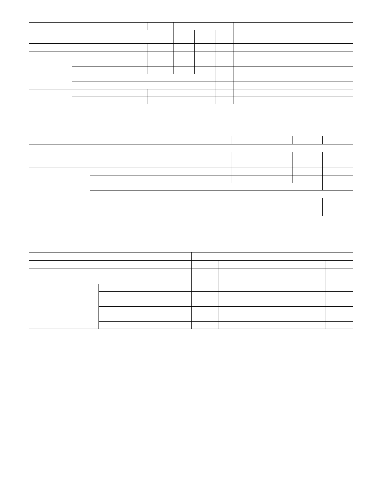
BLOWER DATA CHA16
CHA16-024 BLOWER PERFORMANCE
@ 230 VOLTS (With Down-Flow Air Openings)
External Static
Pressure
in. w.g. Pa cfm L/s cfm L/s cfm L/s cfm L/s
0 0 1370 645 950 450 875 415 660 310
.05 12 1365 645 955 450 880 415 670 315
.10 25 1350 635 960 455 885 420 675 320
.15 37 1340 630 960 455 885 420 680 320
.20 50 1320 625 955 450 880 415 680 320
.25 62 1300 615 950 450 875 415 680 320
.30 75 1280 605 940 445 870 410 675 320
.40 100 1220 575 920 435 850 400 660 310
.50 125 1150 545 880 415 820 385 630 295
.60 150 1070 505 835 395 775 365 585 275
.70 175 975 460 780 370 725 340 535 250
.75 185 925 435 745 350 700 330 500 235
NOTE Ċ For 208v unit operation, derate air volume by 7%. All air data is meaĆ
sured external to the unit with dry coil and without air filter.
Air Volume at Various Blower Speeds
High
MediumĆ
High
MediumĆ
Low
Low
CHA16-024 BLOWER PERFORMANCE
@ 230 VOLTS (With Horizontal Air Openings)
External Static
Pressure
in. w.g. Pa cfm L/s cfm L/s cfm L/s cfm L/s
Air Volume at Various Blower Speeds
High
MediumĆ
High
MediumĆ
Low
Low
0 0 1405 665 905 425 820 385 620 295
.05 12 1400 660 935 440 845 400 640 300
.10 25 1385 655 955 450 865 410 655 310
.15 37 1370 645 975 460 880 415 665 315
.20 50 1355 640 985 465 890 420 670 315
.25 62 1335 630 990 465 895 420 670 315
.30 75 1310 620 985 465 890 420 670 315
.40 100 1260 595 965 455 870 410 650 305
.50 125 1195 565 915 430 830 390 615 290
.60 150 1120 530 840 395 865 410 560 265
.70 175 1035 490 740 350 675 320 490 230
.75 185 990 465 685 325 620 295 445 210
NOTE Ċ For 208v unit operation, derate air volume by 7%. All air data is measured
external to the unit with dry coil and without air filter.
CHA16-030 BLOWER PERFORMANCE
@ 230 VOLTS (With Down-Flow Air Openings)
External Static
Pressure
in. w.g. Pa cfm L/s cfm L/s cfm L/s cfm L/s
Air Volume at Various Blower Speeds
High
MediumĆ
High
MediumĆ
Low
Low
0 0 1355 640 1255 590 1105 520 900 425
.05 12 1345 635 1250 590 1100 520 910 430
.10 25 1330 630 1245 590 1090 515 915 430
.15 37 1310 620 1235 585 1080 510 915 430
.20 50 1290 610 1220 575 1070 505 910 430
.25 62 1270 600 1205 570 1055 500 900 425
.30 75 1245 590 1180 555 1035 490 890 420
.40 100 1190 560 1130 535 990 465 855 405
.50 125 1125 530 1060 500 935 440 805 380
.60 150 1050 495 980 560 870 410 735 345
.70 175 960 455 885 420 790 375 655 310
.75 185 915 430 835 395 745 350 605 285
NOTE Ċ For 208v unit operation, derate air volume by 7%. All air data is measured
external to the unit with dry coil and without air filter.
CHA16-030 BLOWER PERFORMANCE
@ 230 VOLTS (With Horizontal Air Openings)
External Static
Pressure
in. w.g. Pa cfm L/s cfm L/s cfm L/s cfm L/s
Air Volume at Various Blower Speeds
High
MediumĆ
High
MediumĆ
Low
Low
0 0 1445 680 1330 630 1105 520 900 425
.05 12 1435 680 1295 610 1105 520 910 430
.10 25 1420 670 1285 605 1105 520 915 430
.15 37 1400 660 1275 600 1100 520 920 435
.20 50 1380 650 1265 595 1095 515 920 435
.25 62 1360 640 1250 590 1085 510 915 430
.30 75 1335 630 1230 580 1070 505 905 425
.40 100 1280 605 1185 560 1035 490 880 415
.50 125 1220 575 1135 535 995 470 840 395
.60 150 1150 545 1070 505 935 440 790 375
.70 175 1070 505 995 470 870 410 720 340
.75 185 1025 485 955 450 830 390 680 320
NOTE Ċ For 208v unit operation, derate air volume by 7%. All air data is measured
external to the unit with dry coil and without air filter.
Page 10
Page 11
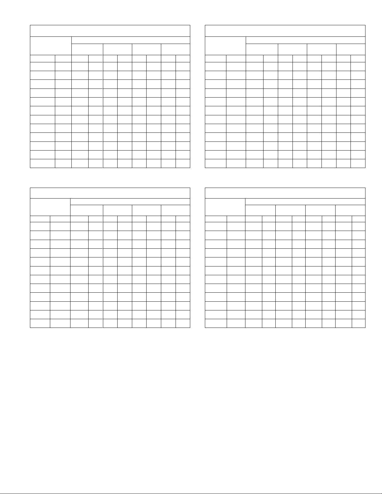
BLOWER DATA CHA16 Cont
External Static
External Static
CHA16-036 BLOWER PERFORMANCE
@ 230 VOLTS (With Down-Flow Air Openings)
External Static
Pressure
in. w.g. Pa cfm L/s cfm L/s cfm L/s cfm L/s
0 0 1415 670 1350 635 1135 530 915 430
.05 12 1395 660 1335 630 1125 530 905 425
.10 25 1375 650 1315 620 111 5 525 895 420
.15 37 1360 640 1290 610 111 0 525 890 420
.20 50 1355 640 1275 600 1105 520 885 420
.25 62 1325 625 1255 590 1095 515 875 415
.30 75 1310 620 1235 585 1085 510 865 410
.40 100 1265 595 1195 565 1060 500 845 400
.50 125 1220 575 1155 545 1020 480 825 390
.60 150 1170 550 1105 520 975 460 785 370
.70 175 1115 525 1045 495 925 435 725 340
.75 185 1085 510 1010 475 895 420 685 325
NOTE Ċ For 208v unit operation, derate air volume by 7%. All air data is meaĆ
sured external to the unit with dry coil and without air filter.
CHA16-036 BLOWER PERFORMANCE
@ 230 VOLTS (With Horizontal Air Openings)
External Static
Pressure
in. w.g. Pa cfm L/s cfm L/s cfm L/s cfm L/s
0 0 1490 705 1460 690 1145 540 920 435
.05 12 1470 695 1440 680 1135 535 910 430
.10 25 1450 685 1420 670 1125 530 900 425
.15 37 1435 675 1395 660 1120 530 895 420
.20 50 1430 675 1375 650 1115 525 890 420
.25 62 1400 660 1355 640 1105 520 880 415
.30 75 1380 650 1335 630 1095 515 870 410
.40 100 1335 630 1285 605 1070 505 850 400
.50 125 1285 605 1235 585 1030 485 830 390
.60 150 1235 585 1195 565 985 465 790 375
.70 175 1185 560 1140 540 935 440 730 345
.75 185 1160 545 1110 525 905 425 690 325
NOTE Ċ All air data is measured external to the unit with dry coil and without air filter.
CHA16-036 BLOWER PERFORMANCE
@ 460/575 VOLTS (With Down-Flow Air Openings)
External Static
Pressure
in. w.g. Pa cfm L/s cfm L/s cfm L/s
0 0 1625 765 1465 690 1100 520
.05 12 1600 755 1445 680 1100 520
.10 25 1570 740 1420 670 1100 520
.15 37 1555 735 1395 660 1095 515
.20 50 1525 720 1385 655 1090 515
.25 62 1485 700 1365 645 1075 505
.30 75 1465 690 1340 630 1070 505
.40 100 1400 660 1285 605 1035 490
.50 125 1335 630 1235 585 1005 475
.60 150 1260 595 1165 550 955 450
.70 175 1170 550 1085 510 875 415
.75 185 1100 520 1045 495 815 385
NOTE Ċ All air data is measured external to the unit with dry coil and without air filter.
Air Volume at Various Blower Speeds
High
High
High Medium Low
MediumĆ
High
Air Volume at Various Blower Speeds
MediumĆ
High
Air Volume at Various Blower Speeds
MediumĆ
Low
MediumĆ
Low
Low
Low
CHA16-036 BLOWER PERFORMANCE
@ 460/575 VOLTS (With Horizontal Air Openings)
External Static
Pressure
in. w.g. Pa cfm L/s cfm L/s cfm L/s
Air Volume at Various Blower Speeds
High Medium Low
0 0 1710 805 1590 750 1105 520
.05 12 1685 795 1565 740 1105 520
.10 25 1655 780 1535 725 1105 520
.15 37 1630 770 1510 715 1100 520
.20 50 1610 760 1490 705 1095 515
.25 62 1570 740 1470 695 1085 510
.30 75 1540 725 1445 680 1075 505
.40 100 1475 695 1385 655 1040 490
.50 125 1405 665 1330 630 1010 475
.60 150 1335 630 1260 595 960 455
.70 175 1240 585 1185 560 885 420
.75 185 1180 555 1150 545 825 390
NOTE Ċ All air data is measured external to the unit with dry coil and without air filter.
CHA16-048 BLOWER PERFORMANCE
@ 230 VOLTS (With Down-Flow Air Openings)
External Static
Pressure
in. w.g. Pa cfm L/s cfm L/s cfm L/s cfm L/s
Air Volume at Various Blower Speeds
High
MediumĆ
High
MediumĆ
Low
Low
0 0 2065 975 1715 810 1515 715 1305 615
.05 12 2055 970 1705 805 1505 710 1300 615
.10 25 2040 965 1690 800 1495 705 1300 615
.15 37 2020 955 1680 795 1485 700 1295 610
.20 50 2000 945 1665 785 1475 695 1290 610
.25 62 1975 930 1650 780 1470 695 1285 605
.30 75 1950 920 1635 770 1450 685 1280 605
.40 100 1885 890 1600 755 1425 670 1260 595
.50 125 1810 855 1565 740 1395 660 1225 580
.60 150 1730 815 1525 720 1360 640 1175 555
.70 175 1645 775 1600 755 1320 625 111 0 525
.75 185 1600 755 1455 685 1295 610 1070 505
NOTE Ċ For 208v unit operation, derate air volume by 7%. All air data is meaĆ
sured external to the unit with dry coil and without air filter.
CHA16-048 BLOWER PERFORMANCE
@ 230 VOLTS (With Horizontal Air Openings)
External Static
Pressure
in. w.g. Pa cfm L/s cfm L/s cfm L/s cfm L/s
Air Volume at Various Blower Speeds
High
MediumĆ
High
MediumĆ
Low
Low
0 0 2140 1010 1785 840 1535 725 1305 615
.05 12 2115 1000 1770 835 1530 720 1300 615
.10 25 2090 985 1755 830 1520 715 1295 610
.15 37 2070 975 1745 825 1510 715 1290 610
.20 50 2045 965 1730 815 1500 710 1285 605
.25 62 2020 955 1715 810 1490 705 1280 605
.30 75 1995 940 1700 800 1480 700 1275 600
.40 100 1935 915 1665 785 1460 690 1260 595
.50 125 1875 885 1630 770 1430 675 1235 585
.60 150 1800 850 1585 750 1400 660 1205 570
.70 175 1710 805 1530 720 1370 645 1170 550
.75 185 1655 780 1495 705 1355 640 1150 545
NOTE Ċ For 208v unit operation, derate air volume by 7%. All air data is meaĆ
sured external to the unit with dry coil and without air filter.
Page 11
Page 12
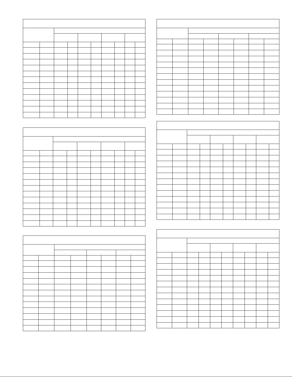
BLOWER DATA CHA16 Cont.
External Static
External Static
External Static
External Static
CHA16-048 BLOWER PERFORMANCE
@ 460/575 VOLTS (With Down-Flow Air Openings)
External Static
Pressure
in. w.g. Pa cfm L/s cfm L/s cfm L/s
0 0 2140 1010 1745 825 1175 555
.05 12 2120 1000 1730 815 1175 555
.10 25 2080 980 1720 810 1170 550
.15 37 2045 965 1710 805 1170 550
.20 50 2005 945 1695 800 1165 550
.25 62 1975 930 1680 795 1160 545
.30 75 1940 915 1665 785 1150 545
.40 100 1870 885 1625 765 1135 535
.50 125 1790 845 1580 745 111 0 525
.60 150 1705 805 1515 715 1075 505
.70 175 1605 760 1430 675 1030 485
.75 185 1555 740 1375 650 1000 470
NOTE Ċ All air data is measured external to the unit with dry coil and without air filter.
Air Volume at Various Blower Speeds
High Medium Low
CHA16-048 BLOWER PERFORMANCE
@ 460/575 VOLTS (With Horizontal Air Openings)
External Static
Pressure
in. w.g. Pa cfm L/s cfm L/s cfm L/s
Air Volume at Various Blower Speeds
High Medium Low
0 0 2160 1020 1815 855 1210 570
.05 12 2125 1005 1800 850 1210 570
.10 25 2095 990 1790 845 1200 565
.15 37 2060 970 1780 840 1200 565
.20 50 2025 955 1760 830 1195 565
.25 62 1990 940 1745 825 1190 560
.30 75 1955 925 1730 815 1185 560
.40 100 1885 890 1690 800 1170 550
.50 125 1805 850 1640 775 1140 540
.60 150 1715 810 1575 745 1105 520
.70 175 1615 760 1495 705 1065 505
.75 185 1560 735 1445 680 1040 490
NOTE Ċ All air data is measured external to the unit with dry coil and without air filter.
CHA16-060 BLOWER PERFORMANCE
@ 230 VOLTS (With DownĆFlow Air Openings)
External Static
Pressure
in. w.g. Pa cfm L/s cfm L/s cfm L/s cfm L/s cfm L/s
Air Volume at Various Blower Speeds
High
MediumĆ
High
Medium
MediumĆ
Low
Low
0 0 2725 1285 2490 1175 2235 1055 1940 915 1620 765
.05 12 2695 1270 2435 1150 2210 1045 1930 910 1625 765
.10 25 2665 1260 2430 1145 2185 1030 1925 910 1625 765
.15 37 2635 1245 2415 1140 2160 1020 1910 900 1610 760
.20 50 2600 1225 2395 1130 2140 1010 1895 895 1590 750
.25 62 2555 1205 2365 1115 2130 1005 1880 885 1580 745
.30 75 2510 1185 2335 1100 2115 1000 1865 880 1565 740
.40 100 2445 1155 2275 1075 2060 970 1830 865 1540 725
.50 125 2385 1125 2230 1050 2005 945 1765 835 1505 710
.60 150 2285 1080 2140 1010 1940 915 1725 815 1455 685
.70 175 2210 1045 2075 980 1880 885 1660 785 1405 665
.75 185 2175 1025 2030 960 1845 870 1615 760 1370 645
NOTE Ċ For 208v unit operation, derate air volume by 7%. All air data is meaĆ
sured external to the unit with dry coil and without air filter.
CHA16-060 BLOWER PERFORMANCE
@ 460/575 VOLTS (With Down-Flow Air Openings)
External Static
Pressure
in. w.g. Pa cfm L/s cfm L/s cfm L/s
Air Volume at Various Blower Speeds
High Medium Low
0 0 2725 1285 2405 1135 1905 900
.05 12 2680 1265 2365 1115 1890 890
.10 25 2635 1245 2325 1095 1870 880
.15 37 2590 1220 2290 1080 1855 875
.20 50 2550 1205 2255 1065 1840 870
.25 62 2515 1185 2220 1050 1820 860
.30 75 2485 1175 2190 1035 1795 845
.40 100 2395 1130 2120 1000 1745 825
.50 125 2325 1095 2050 965 1680 795
.60 150 2235 1055 1970 930 1570 740
.70 175 2150 1015 1900 895 1560 735
.75 185 2100 990 1860 880 1515 715
NOTE Ċ All air data is measured external to the unit with dry coil and without air filter.
CHA16-060 BLOWER PERFORMANCE
@ 230 VOLTS (With Horizontal Air Openings)
External Static
Pressure
in. w.g. Pa cfm L/s cfm L/s cfm L/s cfm L/s cfm L/s
Air Volume at Various Blower Speeds
High
MediumĆ
High
Medium
MediumĆ
Low
Low
0 0 2850 1345 2530 1195 2255 1065 1970 930 1640 775
.05 12 2820 1330 2475 1170 2230 1050 1965 925 1645 775
.10 25 2790 1315 2475 1170 2205 1040 1955 925 1645 775
.15 37 2760 1300 2455 1160 2180 1030 1940 915 1630 770
.20 50 2725 1285 2435 1150 2160 1020 1925 910 1610 760
.25 62 2680 1265 2405 1135 2150 1015 1910 900 1600 755
.30 75 2630 1240 2375 1120 2135 1010 1895 895 1585 750
.40 100 2570 1215 2315 1090 2080 980 1860 880 1560 735
.50 125 2510 1185 2270 1070 2025 955 1795 845 1525 720
.60 150 2410 1135 2180 1030 1960 925 1755 830 1475 695
.70 175 2335 1100 2115 1000 1900 895 1690 800 1425 670
.75 185 2300 1085 2070 975 1865 880 1650 780 1390 655
NOTE Ċ For 208v unit operation, derate air volume by 7%. All air data is meaĆ
sured external to the unit with dry coil and without air filter.
CHA16-060 BLOWER PERFORMANCE
@ 460/575 VOLTS (With Horizontal Air Openings)
External Static
Pressure
in. w.g. Pa cfm L/s cfm L/s cfm L/s
Air Volume at Various Blower Speeds
High Medium Low
0 0 2850 1345 2430 1145 1940 915
.05 12 2805 1325 2385 1125 1920 905
.10 25 2760 1300 2345 1105 1905 900
.15 37 2715 1280 2310 1090 1885 890
.20 50 2670 1260 2275 1075 1870 880
.25 62 2640 1245 2240 1055 1850 875
.30 75 2605 1230 2210 1045 1825 860
.40 100 2515 1185 2140 1010 1775 840
.50 125 2445 1155 2120 1000 1710 805
.60 150 2355 1110 1990 940 1600 755
.70 175 2270 1070 1920 905 1590 750
.75 185 2225 1050 1880 885 1545 730
NOTE - All air data is measured external to the unit with dry coil and without air filter.
Page 12
Page 13
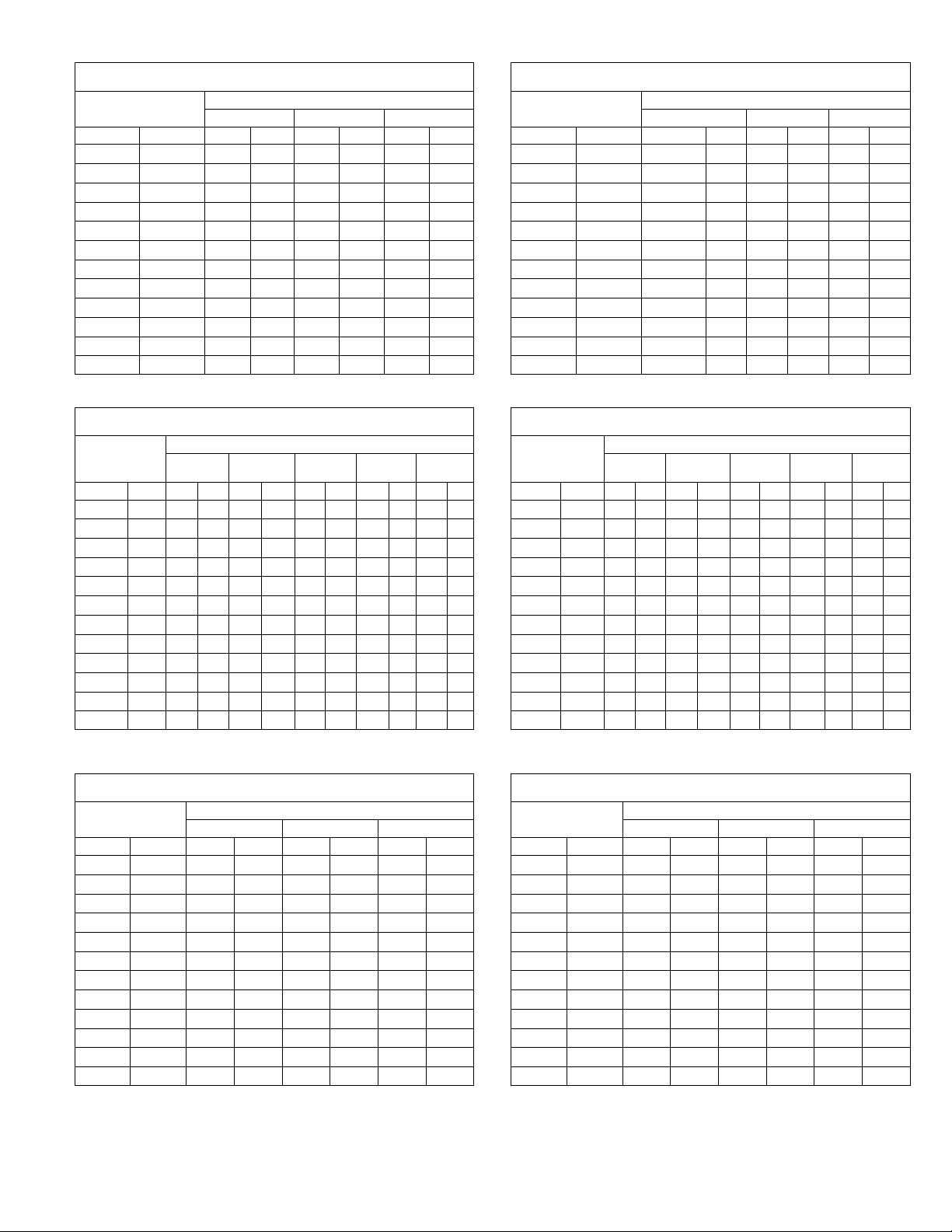
BLOWER DATA CHP16/20
CHP16/20Ć024 BLOWER PERFORMANCE
230 VOLTS (With DownĆFlow Air Openings)
External Static
Pressure
in. w.g. Pa cfm L/s cfm L/s cfm L/s cfm L/s
0 0 1385 655 1025 485 900 425 685 325
.05 12 1380 650 1035 490 915 430 700 330
.10 25 1365 645 1045 495 925 435 710 335
.15 37 1350 635 1045 495 930 440 715 335
.20 50 1330 630 1040 490 930 440 715 335
.25 62 1305 615 1030 485 925 435 715 335
.30 75 1275 600 1010 475 915 430 705 335
.40 100 1205 570 965 455 880 415 680 320
.50 125 1120 530 890 420 820 385 640 300
.60 150 1015 480 800 380 740 350 585 275
.70 175 900 425 685 325 640 300 510 240
.75 185 835 395 615 290 580 275 470 220
NOTE Ċ For 208v unit operation, derate air volume by 7% All air data is measured
external to the unit with dry coil and without air filter.
CHP16/20Ć024 BLOWER PERFORMANCE
230 VOLTS (With Horizontal Air Openings)
External Static
Pressure
in. w.g. Pa cfm L/s cfm L/s cfm L/s cfm L/s
0 0 1435 675 1035 490 895 420 625 295
.05 12 1420 670 1050 495 915 430 645 305
.10 25 1400 660 1060 500 925 435 660 310
.15 37 1380 650 1060 500 935 440 670 315
.20 50 1360 640 1060 500 935 440 675 320
.25 62 1335 630 1050 495 930 440 675 320
.30 75 1305 615 1035 490 920 435 670 315
.40 100 1235 585 985 465 875 415 650 305
.50 125 1155 545 910 430 810 380 605 285
.60 150 1065 505 810 380 720 340 545 255
.70 175 960 455 690 325 605 285 465 220
.75 185 905 425 620 295 540 255 415 195
NOTE Ċ For 208v unit operation, derate air volume by 7% All air data is measured
external to the unit with dry coil and without air filter.
Air Volume at Various Blower Speeds
High
High
MediumĆ
High
Air Volume at Various Blower Speeds
MediumĆ
High
MediumĆ
Low
MediumĆ
Low
Low
Low
CHP16/20Ć030 BLOWER PERFORMANCE
230 VOLTS (With Horizontal Air Openings)
External Static
Pressure
in. w.g. Pa cfm L/s cfm L/s cfm L/s cfm L/s
Air Volume at Various Blower Speeds
High
MediumĆ
High
MediumĆ
Low
Low
0 0 1485 700 1345 635 111 5 525 920 435
.05 12 1480 700 1340 630 1120 530 930 440
.10 25 1465 690 1335 630 1120 530 940 445
.15 37 1455 685 1325 625 111 5 525 945 445
.20 50 1435 675 1315 620 111 0 525 945 445
.25 62 1420 670 1305 615 1105 520 940 445
.30 75 1400 660 1285 605 1095 515 935 440
.40 100 1350 635 1250 590 1065 505 910 430
.50 125 1295 610 1200 565 1025 485 875 415
.60 150 1230 580 1145 540 975 460 820 385
.70 175 1160 545 1075 505 915 430 755 355
.75 185 1120 530 1040 490 885 420 720 340
NOTE Ċ For 208v unit operation, derate air volume by 7% All air data is measured
external to the unit with dry coil and without air filter.
CHP16/20Ć036 BLOWER PERFORMANCE
230 VOLTS (With DownĆFlow Air Openings)
External Static
Pressure
in. w.g. Pa cfm L/s cfm L/s cfm L/s cfm L/s
Air Volume at Various Blower Speeds
High
MediumĆ
High
MediumĆ
Low
Low
0 0 1360 640 1270 600 1070 505 890 420
.05 12 1355 640 1250 590 1060 500 885 420
.10 25 1350 635 1230 580 1050 495 880 415
.15 37 1330 630 1220 575 1035 490 870 410
.20 50 1310 620 1210 570 1020 480 860 405
.25 62 1295 610 1190 560 1005 475 845 340
.30 75 1280 605 1170 550 990 470 830 390
.40 100 1230 580 1130 535 960 455 800 380
.50 125 1170 550 1070 505 910 430 760 360
.60 150 1100 520 990 465 850 400 700 330
.70 175 1020 480 890 420 780 370 620 295
.75 185 975 460 830 390 740 350 570 270
NOTE Ċ For 208v unit operation, derate air volume by 7% All air data is measured
external to the unit with dry coil and without air filter.
CHP16/20Ć030 BLOWER PERFORMANCE
230 VOLTS (With DownĆFlow Air Openings)
External Static
Pressure
in. w.g. Pa cfm L/s cfm L/s cfm L/s cfm L/s
Air Volume at Various Blower Speeds
High
MediumĆ
High
MediumĆ
Low
Low
0 0 1485 700 1250 590 1085 500 905 425
.05 12 1460 690 1250 590 1075 505 900 425
.10 25 1430 675 1240 585 1070 505 895 420
.15 37 1400 660 1235 585 1060 500 890 420
.20 50 1375 650 1225 580 1045 495 885 420
.25 62 1345 635 1215 575 1035 490 875 415
.30 75 1315 620 1200 565 1020 480 865 410
.40 100 1255 590 1165 550 990 465 835 395
.50 125 1190 560 1125 530 950 450 805 380
.60 150 1125 530 1075 510 910 430 770 365
.70 175 1060 500 1015 480 865 410 725 340
.75 185 1025 485 985 465 840 395 700 330
NOTE Ċ For 208v unit operation, derate air volume by 7% All air data is measured
external to the unit with dry coil and without air filter.
Page 13
CHP16/20Ć036 BLOWER PERFORMANCE
230 VOLTS (With Horizontal Air Openings)
External Static
Pressure
in. w.g. Pa cfm L/s cfm L/s cfm L/s cfm L/s
Air Volume at Various Blower Speeds
High
MediumĆ
High
MediumĆ
Low
Low
0 0 1450 685 1370 645 1080 510 900 425
.05 12 1430 675 1350 635 1070 505 890 420
.10 25 1410 665 1330 630 1060 500 880 415
.15 37 1395 660 1310 615 1055 500 875 415
.20 50 1380 650 1290 610 1050 495 870 410
.25 62 1360 640 1270 600 1040 490 860 405
.30 75 1340 630 1250 590 1030 485 850 400
.40 100 1300 615 1210 570 1010 475 830 390
.50 125 1250 590 1170 550 970 460 810 380
.60 150 1200 565 1120 530 930 440 770 365
.70 175 1150 545 1060 500 890 420 710 335
.75 185 1125 530 1025 485 870 410 670 315
NOTE Ċ For 208v unit operation, derate air volume by 7% All air data is measured
external to the unit with dry coil and without air filter.
Page 14
BLOWER DATA CHP16/20 Cont.
External Static
External Static
External Static
External Static
CHP16/20Ć036 BLOWER PERFORMANCE
460 VOLTS (With DownĆFlow Air Openings)
External Static
Pressure
in. w.g. Pa cfm L/s cfm L/s cfm L/s
0 0 1560 735 1380 650 1070 505
.05 12 1555 735 1355 640 1075 505
.10 25 1540 725 1330 630 1080 510
.15 37 1510 715 1320 625 1070 505
.20 50 1475 695 1315 620 1060 500
.25 62 1450 685 1295 610 1040 490
.30 75 1430 675 1270 600 1025 485
.40 100 1360 640 1215 575 980 460
.50 125 1280 605 1145 540 925 435
.60 150 1185 560 1045 495 850 400
.70 175 1070 505 925 435 750 355
.75 185 990 465 860 405 680 320
NOTE Ċ All air data is measured external to the unit with dry coil and without air filter.
CHP16/20Ć036 BLOWER PERFORMANCE
460 VOLTS (With Horizontal Air Openings)
External Static
Pressure
in. w.g. Pa cfm L/s cfm L/s cfm L/s
0 0 1665 785 1490 705 1080 510
.05 12 1640 775 1465 690 1080 510
.10 25 1610 760 1440 680 1080 510
.15 37 1585 750 1420 670 1075 505
.20 50 1555 735 1400 660 1070 505
.25 62 1525 720 1380 650 1060 500
.30 75 1495 705 1355 640 1050 495
.40 100 1435 675 1300 615 1015 480
.50 125 1365 645 1250 590 985 465
.60 150 1295 610 1180 555 935 440
.70 175 1205 570 1100 520 860 405
.75 185 1145 540 1060 500 800 380
NOTE Ċ All air data is measured external to the unit with dry coil and without air filter.
CHP20-042 CHP16/20Ć048 BLOWER PERFORMANCE
230 VOLTS (With Down-Flow Air Openings)
External Static
Pressure
in. w.g. Pa cfm L/s cfm L/s cfm L/s cfm L/s
0 0 2015 950 1610 760 1425 670 1240 585
.05 12 2000 945 1595 755 1420 670 1235 585
.10 25 1980 935 1580 745 1415 670 1235 585
.15 37 1960 925 1575 745 1415 670 1230 580
.20 50 1935 915 1560 735 1405 665 1225 580
.25 62 1910 900 1540 725 1395 660 1215 575
.30 75 1885 890 1520 715 1385 655 1205 570
.40 100 1825 860 1485 700 1355 640 1185 560
.50 125 1760 830 1445 680 1315 620 1160 550
.60 150 1690 800 1395 660 1260 595 1130 535
.70 175 1615 760 1335 630 1190 560 1095 515
.75 185 1575 745 1300 615 1145 540 1065 505
NOTE Ċ For 208v unit operation, derate air volume by 7% All air data is measured
external to the unit with dry coil and without air filter.
Air Volume at Various Blower Speeds
High Medium Low
Air Volume at Various Blower Speeds
High Medium Low
Air Volume at Various Blower Speeds
High
MediumĆ
High
MediumĆ
Low
Low
CHP20-042 CHP16/20Ć048 BLOWER PERFORMANCE
230 VOLTS (With Horizontal Air Openings)
External Static
Pressure
in. w.g. Pa cfm L/s cfm L/s cfm L/s cfm L/s
Air Volume at Various Blower Speeds
High
MediumĆ
High
MediumĆ
Low
Low
0 0 2075 980 1675 790 1445 680 1275 600
.05 12 2060 970 1660 785 1440 680 1270 600
.10 25 2040 965 1645 775 1435 675 1270 600
.15 37 2020 955 1635 770 1435 675 1265 595
.20 50 1995 940 1620 765 1425 670 1260 595
.25 62 1965 930 1600 755 1415 670 1250 590
.30 75 1940 915 1580 745 1405 665 1240 585
.40 100 1880 890 1545 730 1375 650 1220 575
.50 125 1815 855 1500 710 1335 630 1195 565
.60 150 1740 820 1450 685 1280 605 1165 550
.70 175 1655 780 1395 660 1210 570 1130 535
.75 185 1605 755 1365 645 1165 550 1110 525
NOTE Ċ For 208v unit operation, derate air volume by 7% All air data is measured
external to the unit with dry coil and without air filter.
CHP16/20Ć048 BLOWER PERFORMANCE
460 VOLTS (With DownĆFlow Air Openings)
External Static
Pressure
in. w.g. Pa cfm L/s cfm L/s cfm L/s
Air Volume at Various Blower Speeds
High Medium Low
0 0 2075 980 1650 780 1105 520
.05 12 2045 965 1635 770 1105 520
.10 25 2015 950 1625 765 1100 520
.15 37 1980 935 1615 760 1100 520
.20 50 1945 920 1600 755 1095 515
.25 62 1915 905 1585 750 1090 515
.30 75 1880 890 1570 740 1085 510
.40 100 1810 855 1535 725 1070 505
.50 125 1735 820 1490 705 1045 495
.60 150 1650 780 1430 675 1010 475
.70 175 1555 735 1355 640 965 455
.75 185 1500 710 1310 620 935 440
NOTE Ċ All air data is measured external to the unit with dry coil and without air filter.
CHP16/20Ć048 BLOWER PERFORMANCE
460 VOLTS (With Horizontal Air Openings)
External Static
Pressure
in. w.g. Pa cfm L/s cfm L/s cfm L/s
Air Volume at Various Blower Speeds
High Medium Low
0 0 2090 985 1755 830 111 5 525
.05 12 2065 975 1740 820 111 5 525
.10 25 2035 960 1720 810 111 0 525
.15 37 2005 945 1705 805 111 0 525
.20 50 1975 930 1685 795 1105 520
.25 62 1950 920 1675 790 1100 520
.30 75 1920 905 1650 780 1095 515
.40 100 1860 880 1600 755 1080 510
.50 125 1790 845 1555 735 1055 500
.60 150 1720 810 1495 705 1020 480
.70 175 1640 775 1425 670 975 460
.75 185 1595 755 1385 655 945 445
NOTE Ċ All air data is measured external to the unit with dry coil and without air filter.
Page 14
Page 15
BLOWER DATA CHP16/20 Cont.
External
External Static
External Static
CHP16/20Ć060 BLOWER PERFORMANCE
230 VOLTS (With Down-Flow Air Openings)
External
Static
Pressure
in. w.g. Pa cfm L/s cfm L/s cfm L/s cfm L/s cfm L/s
0 0 2450 1155 2200 1040 1990 940 1760 830 1460 690
.05 12 2430 1145 2180 1030 1980 935 1750 825 1470 695
.10 25 2410 1135 2170 1025 1970 930 1740 820 1490 705
.15 37 2390 1130 2160 1020 1960 925 1730 815 1500 710
.20 50 2360 111 5 2140 1010 1950 920 1720 810 1490 705
.25 62 2340 1105 2120 1000 1930 910 1710 805 1490 705
.30 75 2320 1095 2100 990 1910 900 1700 800 1480 700
.40 100 2270 1070 2060 970 1880 885 1670 780 1470 695
.50 125 2230 1052 2010 950 1830 865 1640 775 1430 675
.60 150 2170 1025 1930 910 1780 840 1600 755 1390 655
.70 175 2120 1000 1890 890 1730 815 1550 730 1340 630
.75 185 2080 980 1850 875 1700 800 1530 720 1310 620
NOTE Ċ For 208v unit operation, derate air volume by 7% All air data is measured
external to the unit with dry coil and without air filter.
Air Volume at Various Blower Speeds
High
MediumĆ
High
Medium
MediumĆ
Low
Low
CHP16/20Ć060 BLOWER PERFORMANCE
460 VOLTS (With DownĆFlow Air Openings)
External Static
Pressure
in. w.g. Pa cfm L/s cfm L/s cfm L/s
Air Volume at Various Blower Speeds
High Medium Low
0 0 2450 1155 2090 985 1740 820
.05 12 2430 1145 2080 980 1740 820
.10 25 2410 1135 2060 970 1730 815
.15 37 2390 1130 2040 965 1720 810
.20 50 2360 1115 2020 955 1710 805
.25 62 2340 1105 2000 945 1700 800
.30 75 2320 1095 1990 940 1680 795
.40 100 2270 1070 1940 915 1630 770
.50 125 2230 1050 1880 885 1590 750
.60 150 2170 1025 1840 870 1520 715
.70 175 2120 1000 1770 835 1460 690
.75 185 2080 980 1740 820 1440 680
NOTE Ċ All air data is measured external to the unit with dry coil and without air filter.
CHP16/20Ć060 BLOWER PERFORMANCE
230 VOLTS (With Horizontal Air Openings)
External Static
Pressure
in. w.g. Pa cfm L/s cfm L/s cfm L/s cfm L/s cfm L/s
High
Air Volume at Various Blower Speeds
MediumĆ
High
Medium
MediumĆ
Low
Low
0 0 2570 1215 2220 1050 2000 945 1780 840 1510 715
.05 12 2560 1210 2210 1045 1990 940 1780 840 1520 715
.10 25 2540 1200 2200 1040 1980 935 1770 835 1530 720
.15 37 2520 1190 2190 1035 1970 930 1770 835 1520 715
.20 50 2500 1180 2180 1030 1960 925 1760 830 1510 715
.25 62 2480 1170 2160 1020 1940 915 1750 825 1510 715
.30 75 2440 1150 2140 1010 1920 905 1740 820 1500 710
.40 100 2390 1130 2100 990 1900 895 1710 805 1470 695
.50 125 2320 1095 2060 970 1860 880 1670 790 1440 680
.60 150 2240 1055 2010 950 1810 855 1630 770 1400 660
.70 175 2160 1020 1950 920 1760 830 1580 745 1350 635
.75 185 2120 1000 1920 905 1720 810 1560 735 1330 630
NOTE Ċ For 208v unit operation, derate air volume by 7% All air data is measured
external to the unit with dry coil and without air filter.
CHP16/20Ć060 BLOWER PERFORMANCE
460 VOLTS (With Horizontal Air Openings)
External Static
Pressure
in. w.g. Pa cfm L/s cfm L/s cfm L/s
Air Volume at Various Blower Speeds
High Medium Low
0 0 2570 1215 2100 990 1760 830
.05 12 2560 1210 2090 985 1770 835
.10 25 2540 1200 2070 975 1760 830
.15 37 2520 1190 2050 965 1760 830
.20 50 2500 1180 2030 960 1750 825
.25 62 2480 1170 2010 950 1740 820
.30 75 2440 1150 2000 945 1720 810
.40 100 2390 1130 1960 925 1670 790
.50 125 2320 1095 1910 900 1620 765
.60 150 2240 1105 1870 880 1550 730
.70 175 2160 1020 1800 850 1490 705
.75 185 2120 1000 1760 830 1470 695
NOTE Ċ All air data is measured external to the unit with dry coil and without air filter.
Page 15
Page 16
ACCESSORY BLOWER DATA CHA/CHP16/20
Unit
Volume
No
Filter
With Optional
With Optional
With
024
030
048
060
Unit
Air
Model
FD9Ć65
024
030
048
060
Model Numb
CHA16 030
Model Numb
CHP16/20 024
CHP16/20 030
CHP16/20-048
FILTER AND ACCESSORY AIR RESISTANCE CHA/CHP16/20
Unit
Model
No.
.
024
030
036
042
060
DIFFUSER AIR RESISTANCE CHA/CHP16/20
Model
No.
024
030
036
o42
060
Air
Volume
cfm L/s
1 in. (25mm)
Filter
Furnished
600 285 .13 (32) .05 (12) .21 (52) .09 (22) .12 (30) .07 (17)
800 380 .15 (37) .05 (12) .27 (67) .13 (32) .18 (45) .10 (25)
1000 470 .18 (45) .06 (15) .34 (85) .18 (45) .26 (65) .15 (37)
1200 565 .21 (52) .09 (22) .42 (104) .24 (60) .35 (87) .21 (52)
1400 660 .25 (62) .15 (37) .51 (127) .31 (77) .46 (114) .29 (72)
1600 755 .15 (37) .05 (12) .40 (99) .27 (67) .30 (75) .17 (42)
1800 850 .17 (42) .06 (15) .48 (119) .33 (82) .35 (87) .19 (47)
2000 945 .20 (50) .08 (20) .56 (139) .39 (97) .40 (99) .22 (55)
2200 1040 .23 (57) .10 (25) .66 (164) .46 (114) .47 (117) .26 (65)
Air
Volume
cfm L/s 2 Ends Open 1 Side 2 Ends Open All Ends & Sides Open
600 285 .12 (30) .11 (27) .08 (20) .08 (20)
800 380 .15 (37) .13 (32) .11 (27) .11 (27)
1000 470 .19 (47) .16 (40) .14 (35) .14 (35)
1200 565 .25 (62) .20 (50) .17 (42) .17 (42)
1400 660 .33 (82) .26 (65) .20 (50) .20 (50)
1600 755 .43 (107) .32 (80) .20 (50) .24 (60)
1800 850 .56 (139) .40 (90) .30 (75) .30 (75)
2000 945 .73 (182) .50 (124) .36 (90) .36 (90)
2200 1040 .95 (236) .63 (157) .44 (109) .44 (109)
Less
Filter
RTD9Ć65 Diffuser
Total Air Resistance Ċ inches water gauge (Pa)
REMD16 DownĆFlow Economizer
With Optional
Pleated
Polyester
2 in. (51mm) Filter
Total Air Resistance Ċ inches water gauge (Pa)
With Optional
Fiberglass
2 in. (51mm)
Filter
EMDH16 Horizontal
Economizer
With
Furnished
1 in. (25mm)
Filter
FD9Ć65
Diffuser
Less
Filter
WET INDOOR COIL AIR RESISTANCE CHA16
er
CHA16-024
CHA16-030
CHA16-036
CHA16-048
CHA16-060
CEILING DIFFUSER AIR THROW DATA CHA16 CHP16/20
Model No. RTD9-65 FD9-65
Air Volume
cfm L/s ft. m ft. m
1000 470
1200 565
1400 660
1600 755
1800 850
2000 945
2200 1040
Effective throw based on terminal velocities of 75 ft. (22.9 m) per minute.
Air Volume
cfm L/s in. w.g. Pa
600 285
800 380
1000 470
1200 565
800 380
1000 470
1200 565
800 380
1000 470
1200 565
1400 660
1600 755
1800 850
2000 945
2200 1040
1600 755
1800 850
2000 945
2200 1040
Effective Throw Effective Throw Ċ ft.
10-17 3-5 15-20 5-6
11-18 3-5 16-22 5-7
12-19 4-6 17-24 5-7
12-20 4-6 18-25 5-8
13-21 4-6 20-28 6-9
14-23 4-7 21-29 6-9
16-25 5-8 22-30 7-9
Air Resistance
0.05 12
0.06 15
0.07 17
0.08 20
0.09 22
0.10 25
0.11 27
0.09 22
0.10 25
0.11 27
0.12 30
0.11 27
0.12 30
0.13 32
0.14 35
0.08 20
0.09 22
0.10 25
0.11 27
(m)
WET INDOOR COIL AIR RESISTANCE CHP16/20
er
CHP16/20-024
CHP16/20-030
CHP16/20-036
CHP20--042
-
CHP16/20-060
Air Volume
cfm L/s in. w.g. Pa
600 285
800 380
1000 470
800 380
1000 470
1200 565
800 380
1000 470
1200 565
1400 660
1400 660
1600 755
1800 850
2000 945
2200 1040
1600 755
1800 850
2000 945
2200 1040
Air Resistance
0.05 12
0.06 15
0.07 17
0.09 22
0.10 25
0.11 27
0.07 17
0.08 20
0.09 22
0.10 25
0.12 30
0.13 32
0.14 35
0.15 37
0.16 40
0.11 27
0.12 30
0.13 32
0.14 35
Page 16
Page 17
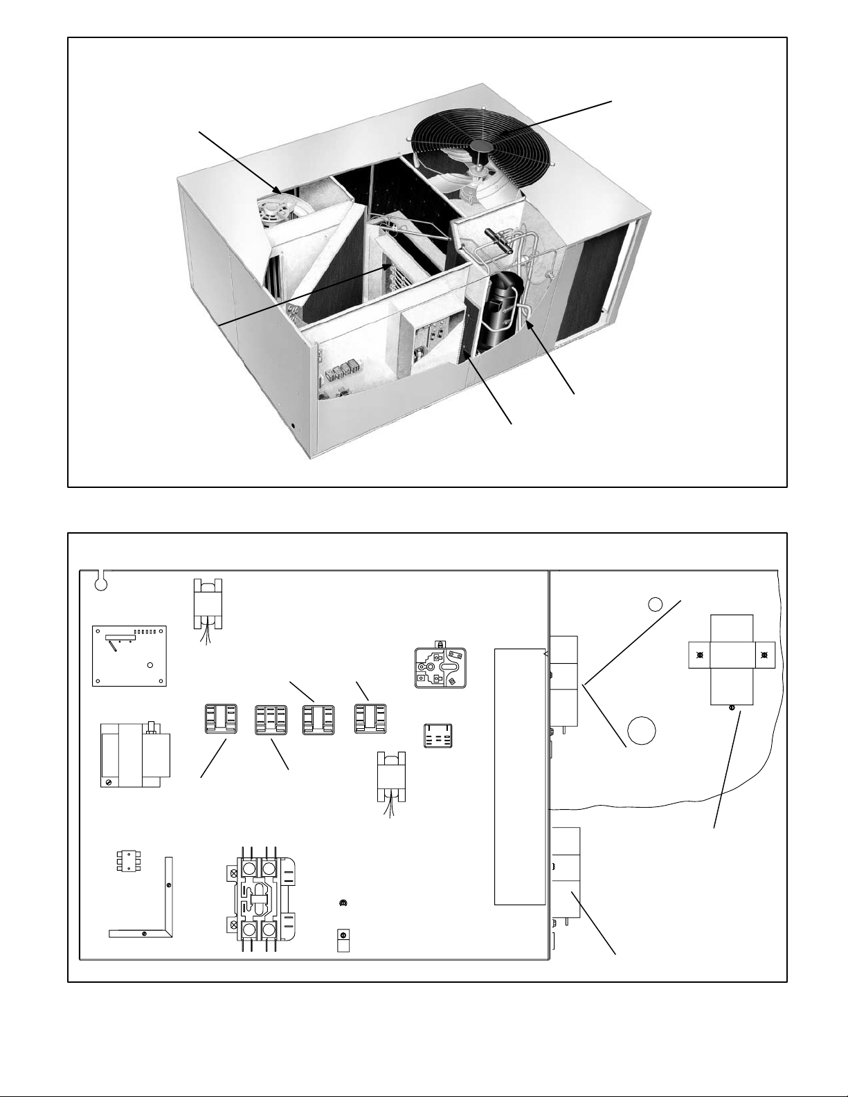
BLOWER ASSEMBLY
ELECTRICHEAT
ELEMENT
CHA/CHP16, CHP20 PARTS ARRANGEMENT
(shown with scroll compressor)
CONDENSER FAN
COMPRESSOR
CONTROL BOX
CMCI DEFROST
CONTROL
TRANSFORMER
T1
TERMINAL STRIP
TB32
TRANSFORMER T4
(024, 030, 036)
FAN RELAY
INBLOOR BLOWER
CONTACTOR K3
COMPRESSOR
CONTACTOR K1
FIGURE 1
CHA/CHP16, CHP20 CONTROL BOX
HARD START RELAY K31
CHA/CHP16-024/030
OUTDOOR
K10
DEFROST
RELAY
TRANSFER
REALY
K8
LATCH RELAY
K6
K4
TRANSFORMER T4
(042, 048, 060)
CAPACITOR C12
ALL P VOLT UNITS
CAPACITOR C1
CHP20-036, -060 G,J,M VOLTS
CHA/CHP16-036 G, J, M VOLTS
ALL Y VOLTAGE UNITS
CAPACITOR C1
CHP16/20-048-G. J, M, VOLTS
CHP16-060-G, J, M, VOLTS
FIGURE 2
Page 17
CAPACITOR C7
CHA/CHP16-024/030
Page 18
I-APPLICATION
CHA/CHP16/20 2, 2 1/2 and 3 ton units are in the one cabiĆ
net size. CHA/CHP16/20 3.5, 4 and 5 ton units are also one
in one cabinet size. All CHA/CHP16/20 model units are apĆ
plicable for commercial, single or three phase installations.
CHA/CHP16/20 models are factory equipped with the hardĆ
ware required for installing Lennox' optional thermostat conĆ
trol systems like the T7300 or T8600 (refer to the EngineerĆ
ing Handbook for more specific application data).
II-UNIT COMPONENTS
CHA/CHP16/20 unit components are shown in figure 1.
A-Control Box Components
CHA/CHP16/20 control box is shown in figure 2. The control
box is located adjacent to the compressor compartment, beĆ
hind the control box access panel in front of the unit.
The condenser fan can be accessed by removing the fan
grill located on top of the unit.
The indoor blower access panel (all units) is located on the
opposite side of the unit from the heating compartment acĆ
cess.
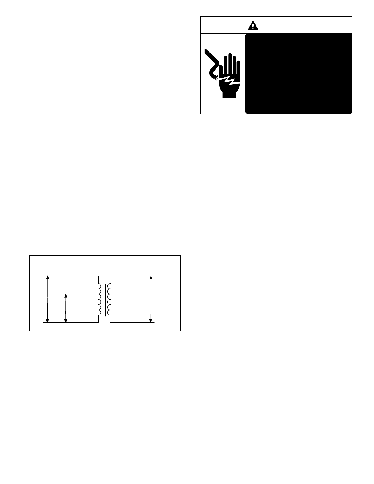
1-Transformer T1
All CHA/CHP16/20 series units use a single line voltage to
24VAC transformer mounted in the control box. The transĆ
former supplies power to control circuits in the unit. TransĆ
formers are rated at 70VA and use two primary voltage taps
as shown in figure 3. T1 is protected by a 3.5 amp circuit
breaker (CB8).
208 / 240 VOLT TRANSFORMER
PRIMARY SECONDARY
ORANGE
240 VOLTS
RED
208 VOLTS
BLUE
24 VOLTS
DANGER
Single -phase units use single
pole contactors. One leg of comĆ
pressor, capacitor and condensĆ
er fan are connected to line voltĆ
age at all times.
Remove all power to disconnect
before servicing.
Electrical shock resulting in
death or injury may result if
power is not disconnected.
NOTE-Contactor K1 is energized by the thermostat
control system. Depending on the control system
installed, the contactor may or may not be immediately
energized upon demand.
3-Indoor Blower Relay K3 (Cooling Speed)
208/230 volt units use a single DPDT relay to energize the
indoor blower motor. 460 volt and 575 volt units use a single
3PDT relay.
CHP16/20 units (singleĆphase and threeĆphase) use a
conventional 2 heat / 2 cool thermostat. Transfer relay
K8 is used to direct power to blower relay K3 depending on
whether the unit is in cooling or heating mode. In cooling
mode transfer relay K8 is deĆenergized and blower relay K3
is energized by thermostat terminal G through K8Ć1 normalĆ
ly closed contacts. In heating mode transfer relay K8 is enĆ
ergized and blower relay K3 is energized directly by transĆ
former T1 through K8Ć1 normally open contacts.
460 (G) voltage units use a unique blower motor which reĆ
quires the 3PDT relay. The motor utilizes the extra set of
N.C. relay contacts to complete an internal circuit when the
motor is on heating speed. Refer to the blower motor section
of this manual for more information.
BLACK
FIGURE 3
YELLOW
2-Cooling Contactor K1
K1 is a 24V to line voltage contactor used to energize the
compressor and condenser fan in response to thermostat
demand. Three-phase units use three-pole double-break
contactors. Single-phase units use single-pole contactors.
Page 18
4-Defrost Relay K4 (CHP Models Only)
Relay K4 initiates defrost in response to demand. K4 is enĆ
ergized when defrost thermostat S6 closes and defrost conĆ
trol CMC1 calls for defrost. Once energized, contacts K4Ć1
open to reset the internal timer to zero, contacts K4Ć2 close
to energize the electric heat (if installed) and K4Ć3 closes to
latch condenser fan relay K10 and defrost relay K4 through
defrost cycle.
Page 19
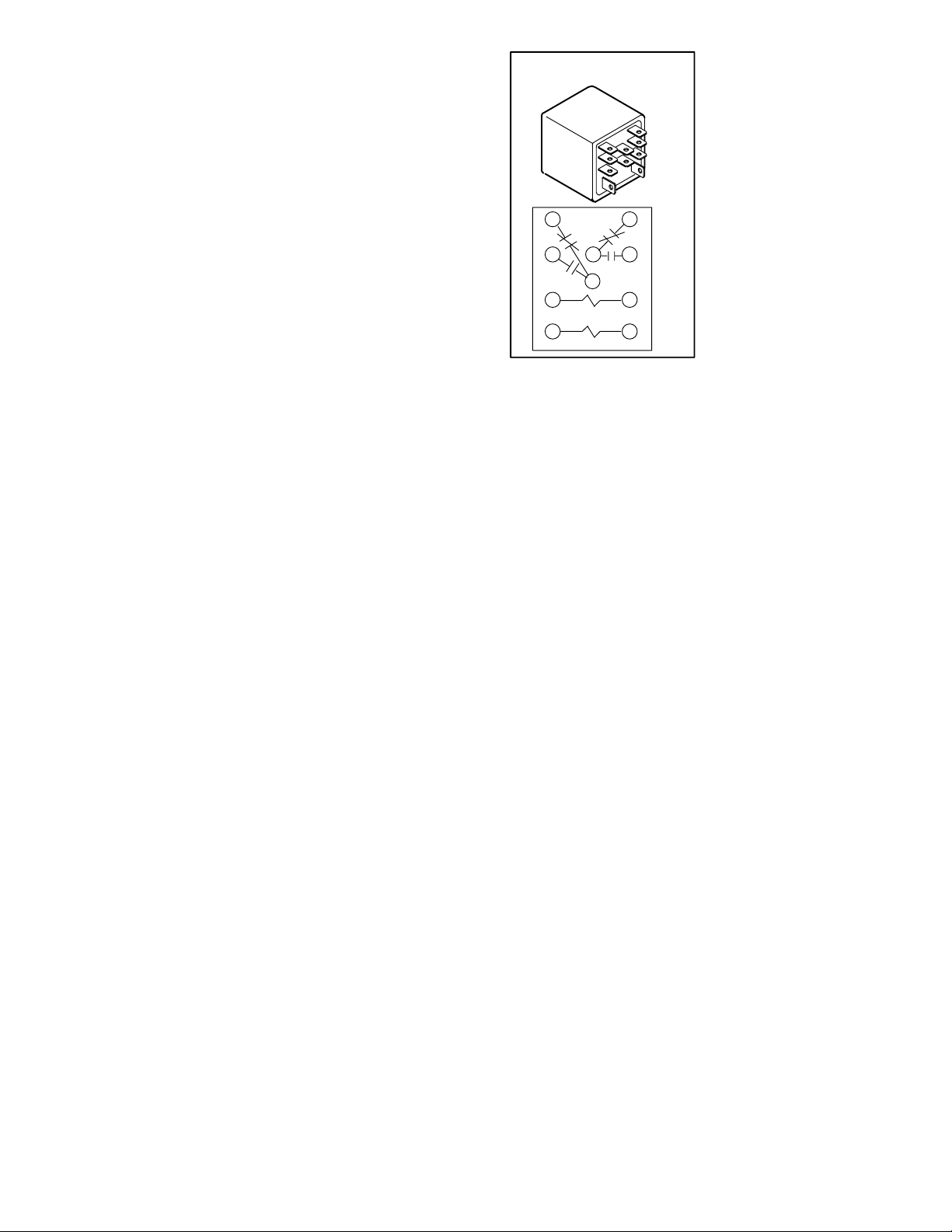
5-Start Capacitor C7
Compressor start capacitor C7 is used in CHA/
CHP16-024/030 units only, and located in the compressor
compartment. C7 is connected in parallel with capacitor
(C12). The capacitor is energized during compressor startĆ
up and is switched off by potential relay K31 when the comĆ
pressor nears full speed. See side of capacitor for ratings.
The start capacitor uses a 15K ohm 2 watt bleed" resistor
connected in parallel with the capacitor terminals. The resisĆ
tor is used to slowly discharge the capacitor when not in use.
6-Dual Capacitor C12
Single phase CHA/CHP16/20 model units use a single
dual" capacitor, connected to both the fan motor and the
compressor. A dual capacitor is two independent capacitors
inside one can. Each side of the capacitor has different ratĆ
ings and will be printed on the side.The capacitor is located
inside the compressor compartment.
7-Condenser Fan Relay K10
Condenser fan relay K10, used in all CHP16/20 units, is a
DPDT relay with a 24V coil. In all units K10 de-energizes conĆ
denser fan B4 in response to defrost demand.
8-Latch Relay K6
CHP16/20 commercial units are designed to use convenĆ
tional heat/cool thermostats and are equipped with latch
relay K6. Latch relay K6 is used in commercial heat pumps
to control operation of the reversing valves when a heat/cool
thermostat is used.
CHP16/20 series units are plumbed so that the unit is in coolĆ
ing mode when the reversing valve is energized. Latch relay
K6 controls operation of the reversing valves and is controlled
by the indoor thermostat.
A latch relay (figure 4) is a special type of relay with two coils;
a SET" coil and a RESET" coil. When 24VAC is applied to
the SET" coil, the normally open contacts close and the norĆ
mally closed contacts open. When power is removed from
the SET" coil, nothing happens; the N.O. contacts remain
closed and the N.C. contacts remain open. The contacts do
not return to their normal position until the RESET" coil is
energized. Once the contacts are reset, they remain in their
normal position when power is removed.
CHP16/20 series units use a
LATCH RELAY K6
DPDT latch relay. One set of
normally open contacts is conĆ
nected in series with thermostat
Y1 and compressor contactor
K1 while the matching normally
closed contacts are connected
in series with thermostat W1
and compressor contactor K1.
14
The other set of normally open
contacts is connected in series
568
10
9
RESET
13 14
12
SET
FIGURE 4
with the reversing valve. When
the SET" coil is energized (Y1),
the normally open contacts
close to energize the reversing
valve (thereby placing the unit in
cooling mode) and to energize
the compressor contactor.
When power is removed from the SET" coil (such as when
cooling demand is satisfied), the normally open contacts remain
closed, the reversing valve remains energized and the unit reĆ
mains in cooling mode.
9-Transfer Relay K8
The combined operation of latch relay K6 and transfer relay
K8 allow the CHP16 to use a conventional heat/cool thermoĆ
stat as opposed to a heat pump thermostat. Transfer relay
K8 switches thermostat blower demand from cooling mode
to heating mode. Relay K8 routes blower demand from the
appropriate thermostat output to the blower relay depending
on whether the unit is in cooling or heating mode.
During cooling mode, the blower relay receives power from
thermostat terminal G (relay K8 deĆenergized). During
heating demand transfer relay K8 is energized. When K8 is
energized, power routing is switched so that the blower
relay receives power from heating thermostat demand
(W1).
10-Potential Relay K31
Relay K31 is used in the CHA/CHP16-024/030 models ONLY
and is located in the control box. It is a potential relay which
controls the operation of the compressor starting circuit. The
relay is normally closed when the compressor (contactor K1)
is de-energized. Capacitor (C7) is connected to a set of norĆ
mally closed K31 contacts and assists the compressor in
starting. When K1 energizes, the compressor immediately beĆ
gins startĆup. K31 remains de-energized during compressor
start-up and the start capacitor (C7) remains in the circuit. As
the compressor gains speed K31 is energized by electromoĆ
tive forces generated by the compressor. When K31 enerĆ
gizes, its contacts open to take the start capacitor out of the
circuit.
Page 19
Page 20
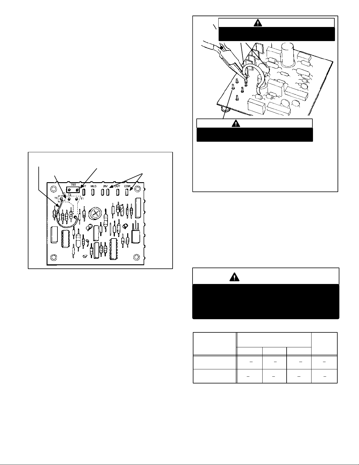
11-Defrost Control CMC1
GU
6
The CMC1 defrost control (figure 5 ) is a solid state control
which provides automatic switching from normal heating operaĆ
tion to defrost mode and back. The control provides maximum
14 minute defrost periods at 30, 60 or 90Ćminute fieldĆchangeĆ
able intervals. Each control monitors thermostat demand and
holds" the timer in place between thermostat demand. A set of
diagnostic pins are also provided for troubleshooting the refrigĆ
eration circuit.
The control contains a solid state timer which switches an exĆ
ternal defrost relay through 1/4" male spades mounted on the
control's circuit board. The control energizes the defrost relay
at regular timed intervals. Defrost thermostat S6 initiates deĆ
frost and pressure switch S46 terminates defrost. If S46 does
not terminate defrost, CMC1 will terminate defrost after 14
minutes.
SOLID STATE DEFROST TIMER
TIMING JUMPER
TIMING PINS
TROUBLESHOOTING
PINS
CONTROL
TERMINALS
IMPORTANT
Prevent control damage. Avoid contact with other
control terminals or control components.
NEEDLE-NOSE
PLIERS
IMPORTANT
Prevent control damage. Do not connect timing
jumper to either TST" pin.
TO CHANGE CONTROL TIMINGS:
1- Turn off all power to the unit to avoid damaging the circuit board.
2- Grasp wire connector firmly with needle nose pliers as shown.
3- Gently pull connector from pin.
4- Select new timing pin. DO NOT SELECT A TST" PIN.
5- Gently push connector onto desired pin (see Table 1 for timings).
Connector is seated when pin snaps.
6- Turn on power to unit.
FIGURE 5
When the indoor thermostat closes (call for heat or cool), deĆ
frost timer initiates 30, 60 or 90Ćminute (depending on how the
control is preset) timing sequence. At the end of the timing seĆ
quence, the control attempts to energize the defrost relay. If
both defrost thermostat and defrost pressure switch are
closed when timing sequence ends, the defrost relay is enerĆ
gized and defrost begins. Consequently, the defrost pressure
switch must open in order for defrost to be terminated (defrost
can also be terminated by the internal timer of the defrost conĆ
trol).
Defrost Control Components
a- Timing Pins 30(T1), 60(T2), 90(T3)
Each of these pins provides different timed interval beĆ
tween defrosts. A jumper connects the pins to circuit
board pin W1. Table 1 shows the timings of each pin.
The defrost interval can be field changed to 30, 60 or 90
minutes. The defrost period (14 minutes) cannot be
changed. To change the interval between defrosts, simĆ
ply remove the jumper from the pin it is connected to and
reconnect the jumper to one of the other available pins
(see figure 6).
FI
RE
b- Timing Jumper
A timing jumper is factory installed on the circuit board
and is used to connect pin W1 to one of three timing
pins. The jumper may be connected to any one timing
pin but must never be connected to the TST" pins. See
following Caution.
IMPORTANT
Potential for control damage.
Do not connect timing jumper to TST" pins.
TST" pins are used only during a test and must
not connect with timing pins.
TABLE 1
DEFROST
CONTROL CMC
TIMINGS
NORMAL
OPERATION
TST" PINS
JUMPERED
TOGETHER
c- 24V" Terminal
Terminal 24V" receives 24VAC from the control transĆ
former. This terminal powers the control's internal timer
and relays. Terminal 24V" must be powered at all times
in order to provide HOLD" between thermostat deĆ
mands.
INTERVAL BETWEEN
DEFROSTS WITH
JUMPER CONNECTED TO:
30 (T1) 60 (T2) 90 (T3)
30 + 3 60 + 6 90 + 9 14 + 1.4
MIN. MIN. MIN. MIN.
7 + 0.7 14 + 1.4 21 + 2.1 3.3 + 0.3
SEC. SEC. SEC. SEC.
DEFROST
TIME
Page 20
Page 21
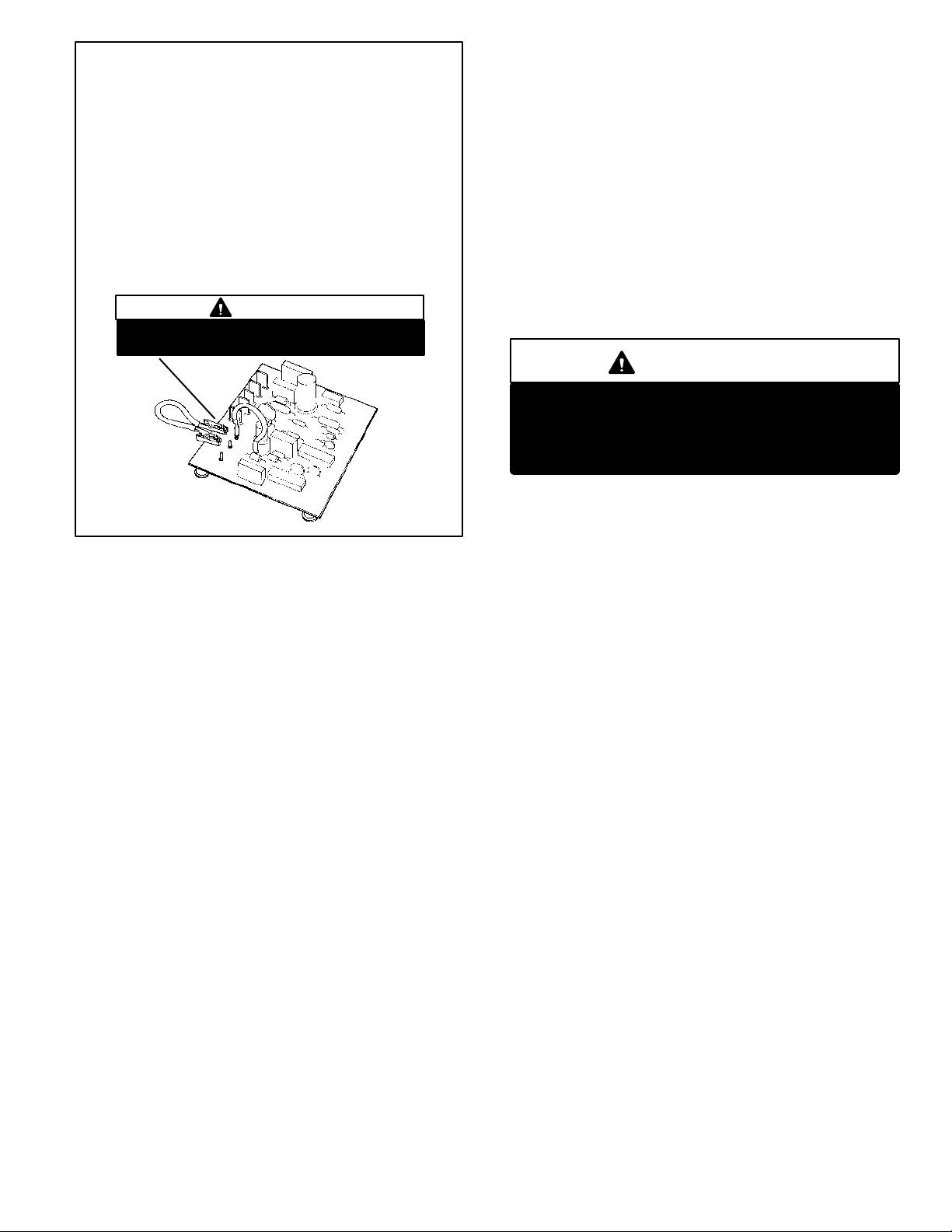
TO PLACE CONTROL IN TEST MODE:
1- Turn off all power to avoid damaging the circuit board.
2- Make sure all control terminals are connected as shown on unit
wiring diagram before attempting to place control in test mode.
See NOTE below.
NOTE - Control will not go into test mode when disconĆ
nected from unit. Unit load must be applied to control termiĆ
nals before the control will go into test mode.
3- Connect jumper to TST" pins as shown.
4- Turn indoor thermostat to heat mode and adjust to highest temperaĆ
ture setting.
5- Turn on power to unit.
6- See Table 1 for control timings in TST" mode.
7- Be sure to turn off power and remove jumper when test is complete.
Turn on power and re-adjust thermostat.
IMPORTANT
Prevent control damage. Avoid contact with other
control terminals or control components.
FIGURE 7
d- COM" Terminal
Terminal COM" provides 24VAC common.
e- HLD" Terminal
Terminal HLD" holds an internal timer in place between
thermostat demands and allows the unit to continue timĆ
ing upon resumption of thermostat demand. When therĆ
mostat demand is present, the control is allowed to count
down to the next defrost. Terminal HLD" is connected
directly to thermostat demand.
f- OUT" Terminal
Terminal OUT" controls defrost when connected to one
side of the defrost relay coil. An internal relay conĆ
nected to terminal OUT" closes (allowing an internal
path from OUT" to COM") to allow external defrost
relay to energize and initiate defrost. At the end of the
defrost period, the internal relay connected to terminal
OUT" opens to de-energize the external defrost relay.
g- RST" Terminal
Terminal RST" resets the internal timer when power is reĆ
moved and begins timer operation when power is returned.
Terminal RST" is connected to terminal COM" through a
set of normally closed defrost relay contacts. When the deĆ
frost relay contacts open terminal RST" loses power (the
path through RST" is disrupted) and internal timer is reset.
The control resumes timing when the defrost relay contacts
close.
h- TST" Pins
Each board is equipped with a set of test pins for use in
troubleshooting the unit. When jumpered together, these
pins reduce the control timing to a fraction of the original
time (see table 1 and figure 7).
IMPORTANT
Prevent control damage.
Control will begin test mode only if normal load
is applied to control terminals. Do not attempt
to operate or test control out of unit.
A defrost period can last up to 14 minutes and can be termiĆ
nated two ways. First, if the defrost pressure switch does not
open within 14 minutes after defrost begins, the internal timer
(by opening the internal path from OUT" to COM") will de-enĆ
ergize the defrost relay and the unit will resume normal operaĆ
tion. Second, if the defrost pressure switch opens during the
14 minute defrost period, the defrost relay is de-energized
and the unit resumes normal operation. Refer to figure 8.
Page 21
Page 22

THERMOSTAT DEMAND
DEFROST THERMOSTAT
DEFROST PRESSURE SWITCH
DEFROST RELAY
THERMOSTAT DEMAND
DEFROST THERMOSTAT
DEFROST PRESSURE SWITCH
DEFROST RELAY
THERMOSTAT DEMAND
DEFROST THERMOSTAT
DEFROST PRESSURE SWITCH
DEFROST RELAY
CHP16/20 SERIES UNITS
TYPICAL DEFROST TIMINGS
NO DEFROST (DEFROST THERMOSTAT IS OPEN)
DEFROST TERMINATED BY DEFROST PRESSURE SWITCH
NORMAL HEATING OPERATION:
30/60/90 MINUTES 30/60/90 MINUTES
NORMAL HEATING OPERATION:
30/60/90 MINUTES
NORMAL HEATING OPERATION:
DEFROST TERMINATED BY TIME
30/60/90 MINUTES 14 MIN 30/60/90 MINUTES
DEFROST PRESSURE SWITCH
OPEN WITHIN 14 MINUTES
CLOSED, ON
OPEN, OFF
14 MIN
THERMOSTAT DEMAND
INTERRUPTED BY THERMOSTAT DEMAND: HOLD" FUNCTION
DEFROST THERMOSTAT
DEFROST PRESSURE SWITCH
DEFROST RELAY
INTERRUPTED BY THERMOSTAT DEMAND: HOLD" FUNCTION
THERMOSTAT DEMAND
DEFROST THERMOSTAT
DEFROST PRESSURE SWITCH
DEFROST RELAY
NORMAL HEATING OPERATION:
30/60/90 MINUTES PLUS HOLD" TIME
DEFROST PERIOD
30/60/90 MINUTES
FIGURE 8
B-Cooling Components (Figures 9 and 10)
Figures 9 and 10 show CHP16/20 heat pump units.
CHP16/20 units will be equipped with reversing valve, deĆ
frost components, drier and check/expansion valve.
CHA16 units will be equipped with a liquid line strainer and
expansion valve (no check). Common components are high
pressure switch, suction and liquid line service gauge ports.
1-Reciprocating Compressor
All CHA/CHP16-024/030 units are equipped with a reciproĆ
cating compressor. All reciprocating compressors are proĆ
tected by internal pressure relief valves for overload and inĆ
ternal crankcase heaters HR1 for proper lubrication. ComĆ
pressor B1 operates during cooling and heating demand,
HOLD"
TIME
HOLD" TIME
14 MINUTES PLUS HOLD" TIME
and is energized by contactor K1 upon receiving thermosaĆ
tat demand. For compressor specifications see compressor
nameplate or ELECTRICAL DATA section in this manual.
DANGER
Shock hazard.
Compressor must be grounded.
Do not operate without protective
cover over terminals. Capacitors
contain high voltage. Disconnect
power before removing cover.
Discharge capacitors before serĆ
vicing unit. Disconnect power beĆ
fore servicing unit.
Can cause unsafe operation, injuĆ
ry or death.
Page 22
Page 23

COOLING COMPONENTS
CHP16-024/030 SHOWN
DRIER
DEFROST PRESSURE SWITCH
S46
HIGH PRESSURE SWITCH
S4
RECIPROCATING COMPRESSOR
B1
REVERSING VALVE
L1
OUTDOOR
TXV VALVE
DEFROST PRESSURE SWITCH
S6
SENSING BULB
DRIER
DEFROST PRESSURE SWITCH
S46
HIGH PRESSURE SWITCH
S4
SCROLL COMPRESSOR
B1
CHP20-024
REVERSING VALVE
L1
OUTDOOR
TXV VALVE
DEFROST PRESSURE SWITCH
S6
FIGURE 9
Page 23
Page 24

COOLING COMPONENTS
CHP20-030, CHA/CHP16/20-036
DRIER
DEFROST PRESSURE SWITCH
S46
HIGH PRESSURE SWITCH
S4
SCROLL COMPRESSOR
B1
CHA/CHP16-048/060, CHP20-042/048/060
INDOOR
TXV VALVE
REVERSING VALVE
L1
OUTDOOR
TXV VALVE
DEFROST THERMOSTAT SWITCH
S6
HIGH PRESSURE SWITCH
S4
DEFROST PRESSURE SWITCH
S46
DRIER
REVERSING VALVE
L1
OUTDOOR
TXV VALVE
DEFROST THERMOSTAT SWITCH
S6
SCROLL COMPRESSOR
B1
FIGURE 10
Page 24
Page 25

2-Scroll Compressor
All CHA/CHP16/20 (exĆ
cept the CHP16-024/030
units) model units utilize a
scroll compressor. The
scroll compressor design
is simple, efficient and reĆ
quires few moving parts. A
cutaway diagram of the
scroll compressor is
shown in figure 11. The
scrolls are located in the
top of the compressor can
and the motor is located in
the bottom of the compresĆ
sor can. The oil level is imĆ
mediately below the motor and oil is pressure fed to the movĆ
ing parts of the compressor. The lower portion of the comĆ
pressor shell is exposed to low side pressure while only the
very top of the shell is exposed to high side pressure.
The scroll is a simple compression concept centered around
the unique spiral shape of the scroll and its inherent properĆ
ties. Figure 12 shows the basic scroll form. Two identical
scrolls are mated together forming concentric spiral shapes
(figure 13). One scroll reĆ
mains stationary, while
the other is allowed to orĆ
bit (figure 14-1). Note that
the orbiting scroll does
not rotate or turn but
merely orbits the stationĆ
ary scroll.
The counterclockwise orbiting scroll draws gas into the outĆ
er crescent shaped gas pocket created by the two scrolls
(figure 14-2). The centrifugal action of the orbiting scroll
seals off the flanks of the scrolls (figure 14-3). As the orbiting
motion continues, the gas is forced toward the center of the
scroll and the gas pocket becomes compressed (figure
14-4).
SCROLL COMPRESSOR
DISCHARGE
SUCTION
FIGURE 11
FIGURE 12
When compressed gas reaches the center, it is discharged
vertically into a chamber and discharge port in the top of the
compressor (figure11). The discharge pressure forcing
down on the top scroll helps seal off the upper and lower
edges (tips) of the scrolls (figure 13). During a single orbit,
several pockets of gas are compressed simultaneously proĆ
viding smooth continuous compression.
CROSS-SECTION OF SCROLLS
DISCHARGE
PRESSURE
TIPS SEALED BY
DISCHARGE PRESSURE
DISCHARGE
STATIONARY SCROLL
SUCTION
ORBITING SCROLL
FIGURE 13
The scroll compressor is tolerant to the effects of liquid reĆ
turn. If liquid enters the scrolls, the orbiting scroll is allowed
to separate from the stationary scroll. The liquid is worked
toward the center of the scroll and is discharged. If the comĆ
pressor is replaced, conventional Lennox cleanup practices
must be used.
Due to its efficiency, the scroll compressor is capable of
drawing a much deeper vacuum than reciprocating comĆ
pressors. Deep vacuum operation can cause internal fusite
arcing resulting in damaged internal parts and compressor
failure. It is permissible to pumpĆdown" the system using
the compressor but never use a scroll compressor for drawĆ
ing a vacuum on the system. This type of damage can be
detected and will result in denial of warranty claims.
CAUTION
The head of a scroll compressor may be hot since
it is in constant contact with discharge gas.
Contact could result in serious burns.
For compressor specifications see compressor nameplate
or ELECTRICAL DATA section in this manual. All compresĆ
sors are protected by internal overload protection circuitry.
Page 25
Page 26

SUCTION
1
SUCTION
POCKET
SUCTION
ORBITING SCROLL
STATIONARY SCROLL
MOVEMENT OF ORBIT
SUCTION
2
FLANKS SEALED
BY CENTRIFIGUAL
FORCE
INTERMEDIATE PRESSURE
GAS
CRECENT SHAPED
GAS POCKET
SUCTION
3
HIGH PRESURE GAS
FIGURE 14
3-Evaporator Coil
All CHA/CHP16/20 units have a single slab evaporator
coil. The CHA16 coils have two rows of rifled copper tubes
fitted with ripple-edged alum
inum fins and the CHP16/20 coils have three, A Thermal
Expansion Valve (TXV) feeds multiple parallel circuits
through the coil. See figure 15.
4-Condenser Coil
All CHA/CHP16/20 units have a single condenser coil. Each
coil in all units has up to two rows of copper tubes fitted with
ripple-edged aluminum enhanced fins.
5-Freezestat Switch S49
All CHA/CHP16/20 model units are equipped with a low
temperature freezestat switch S49. S49 is wired in series
with high pressure switch S4 and compressor contactor K1.
S49 is a SPST N.C. auto-reset switch which opens at 29ºF ±
3 ºF (-1.7ºC 1.7 ºC) on temperature drop and closes at 58ºF
± 4 ºF (14.4ºC ± 2.2 ºC) on a temperature rise. To prevent coil
icing, S49 opens during compressor operation to temporariĆ
ly disable the compressor until the coil warms sufficiently to
melt any accumulated frost.
If S49 trips frequently due to coil icing, check the unit charge,
air flow and filters before allowing unit back in operation.
Make sure to eliminate conditions which might promote ice
build up.
6-High Pressure Switch S4
High pressure switch S4 is standard on all CHP16/20 model
units. S4 is a manually reset SPST N.C. high pressure
switch which opens on pressure rise. The switch is located
on the discharge line and wired in series with compressor
contactor K1. When discharge pressure rises above
450±10 psig (3103 kPa± 69 kPa) the switch opens and the
4
compressor is de-energized (the economizer can continue
to operate). After the problem has been found and corĆ
rected, the switch can be reset by pushing-in the switch butĆ
ton.
EVAPORATOR PLUMBING
CHP16/20-030/036 SHOWN
EQUALIZER
LINE
SENSING
BULB
FIGURE 15
DISCHARGE
POCKET
EXPANSION
VALV E
LIQUID
LINE
7-Reversing Valve L1
All CHP16/20 units are equipped with refrigerant reversing
valve L1. L1 has a 24VAC solenoid coil used to reverse reĆ
frigerant flow during unit operation. L1 is connected in the
vapor line of the refrigerant circuit. Internal thermostat wiring
energizes L1 during cooling demand and de-energizes durĆ
ing heatingdemand. When thermostat selection is out of
cooling mode L1 is de-energized.
Page 26
Page 27

8-Drier
11-Low Ambient Bypass Relay K58
All CHP16/20 units have a biflo with filter drier located in the
liquid line of each refrigerant circuit at the exit of the conĆ
denser coil. The drier removes contaminants and moisture
from the system.
9-Defrost Thermostat S6
Defrost thermostat S6 works in conjunction with defrost conĆ
trol CMC1 to initiate defrost. The switch is a SPST N.O. therĆ
mostat located on the liquid line between the outdoor coil
distributor and the outdoor coil thermal expansion valve. It
remains open during normal cooling and heating operation
(to prevent defrosting) and defrost timer CMC1 continues to
accumulate time. When outdoor coil temperature drops beĆ
low 35°F +
enabled (call for defrost). If S6 is closed when CMC1 checks
for defrost (every 30, 60 or 90 minutes) then defrost relay K4
is energized. S6 remains closed until liquid line temperature
rises above 60°F +
Defrost thermostat S6 is intended only to initiate defrost.
Pressure switch S46 is used to terminate defrost. Once deĆ
frost starts, contacts K4Ć3 close to latchĆin K10 and K4. TypĆ
ically S6 will open before the end of the 14 minute defrost
period leaving relay K4 energized through contacts K4-3.
4°F, the switch closes and the defrost circuit is
5°F.
10-Defrost Pressure Switch S46
Defrost pressure switch S46 is a SPST N.C. pressure switch
located in the compressor discharge line.
The purpose of the latch circuit is to ensure thorough defrost
by forcing defrost relay K4 to terminate only when S46 is satĆ
isfied or after the 14 minute defrost time period. When disĆ
charge (head) pressure during defrost rises above 275psi +
10psi (1896 69 kPa) the switch opens. At 275psi (1896
kPa), the condensing temperature of HCFCĆ22 refrigerant is
approximately 125°F (52°). Head pressure builds rapidly
due to the outdoor fan being disabled during defrost. By the
time head pressure is elevated to 275psi (1896 kPa), the
condensing temperature is elevated to the point that the outĆ
door coil is defrosted.
If S46 opens during defrost, defrost is terminated (K4 is deĆ
energized). S46 automatically resets (closes) when the unit
resumes heating operation and discharge (head) pressure
drops below 195psi + 10psi.
Optional low ambient bypass relay K58 is a N.O. DPDT relay
with a 24VAC coil. K58 is wired in parallel with compressor
reversing valve (L1). When L1 is energized in the cooling
cycle, K58 is also energized, opening K58-1. Therefore,
K58-1 is always closed during heating demand bypassing
low ambient switch S11. This allows the fan to operate durĆ
ing heating demand and to cycle during cooling demand.
12-Low Ambient Switch S11
Optional low ambient switch S11 is an auto-reset SPST N.O.
pressure switch which allows for mechanical cooling operaĆ
tion at low outdoor temperatures. S11 is located in the liquid
line prior to the indoor coil section. When liquid pressure
rises to 275 10 psig (1896 69 kPa), the switch closes
and the condenser fan is energized. When liquid pressure in
the refrigerant circuit drops to 150 10 psig (1034 69
kPa), the switch opens and the condenser fan is de-enerĆ
gized. This intermittent fan operation results in higher evapĆ
orating temperature allowing the system to operate without
icing the evaporator coil and losing capacity.
C-Condenser Fan and Indoor Blower
1-Condenser Fan and Blower Motor B4
See specifications section of this manual for the specificaĆ
tions of condenser fans used. In all CHP units. the condensĆ
er fan is energized by contactor K1 and condenser contacĆ
tor K10. In all CHA units the condenser fan is controlled by
contactor K1.
2-Capacitors C1 & C12
All three phase model units use singleĆphase PSC outdoor
fan motors which requires a run capacitor. C1 is located in
the compressor compartment. Single phase units use a dual
capacitor C12 instead of C1. The dual capacitor is shared
between the compressor and outdoor fan. Ratings for caĆ
pacitors will be on outdoor fan motor nameplate.
3-Blower Motor B3 & Capacitor C4
All CHA/CHP16/20 series units use singleĆphase PSC blowĆ
er motors. A single run capacitor C4 is mounted on the blowĆ
er housing. Ratings for capacitor will be on motor nameĆ
plate. All motors use multiple speed taps. Typically, the high
speed tap is energized during compressor operation and a
lower speed tap is energized during heating operation. See
motor nameplate or ELECTRICAL DATA section for motor
specifications.
Page 27
Page 28

III-OPTIONAL ECH16 ELECTRIC HEAT
A-Matchups and Ratings
Tables 4 through 15 show all possible CHP16/20 to ECH16
matchups. Also shown in the tables are ECH16 electrical
ratings.
B-Electric Heat Components
ECH16 parts arrangement is shown in figure 18. All ECH16
units consist of electric heating elements exposed directly to
the airstream. Elements are sequenced on and off by heat
relays or contactors in response to thermostat demand.
1-Relay K15
Relay K15 is a singleĆpole singleĆthrow relay located on
the control panel of all commercial singleĆphase ECH16
units (15, 20 and 25 kW). K15 is equipped with a 24VAC
coil which is energized when pilot relay K43 closes.
When K15 is energized, the first stage heating elements
are energized. (HE1 in ECH16Ć15; HE1 and HE2 in
ECH16Ć20 and ECH16Ć25).
2-Contactor K15
Contactor K15 is a threeĆpole doubleĆbreak contactor
used in all commercial threeĆphase ECH16 units. K15 is
equipped with a 24VAC coil which is energized when piĆ
lot relay K43 closes. When K15 is energized, the first
stage heating elements are energized.
Contactor K15 used in ECH16Ć15Ć1Y and ECH16Ć25Ć1G
units is equipped with a set of auxiliary singleĆpole
doubleĆthrow contacts. The auxiliary contacts are not
used in this application.
3-Relay K16
Relay K16 is a singleĆpole singleĆthrow relay located on
the control panel of all commercial singleĆphase ECH16
units (15, 20 and 25 kW). K16 is equipped with a 24VAC
coil which is energized when pilot relay K43 closes.
When K16 is energized, the second stage heating eleĆ
ments are energized (HE2 in ECH16Ć15; HE3 and HE4
in ECH16Ć20 and ECH16Ć25).
4-Contactor K16
Contactor K16 is a threeĆpole doubleĆbreak contactor
used in commercial 20 and 25 kW threeĆphase ECH16
units. K16 is equipped with a 24VAC coil which is enerĆ
gized when time delay DL2 closes. When K16 is enerĆ
gized, the second stage heating elements are enerĆ
gized.
5-Relay K17
Relay K17 is a singleĆpole singleĆthrow relay located on
the control panel of all commercial singleĆphase ECH16
units (15, 20 and 25 kW). K17 is equipped with a 24VAC
coil which is energized when pilot relay K43 closes.
When K17 is energized, the third stage heating eleĆ
ments are energized (HE3 in ECH16Ć15; HE5 and HE6
in ECH16Ć20 and ECH16Ć25).
6-Resistor R6
A resistor is used in parallel with the coil of heat relay K32
in ECH16RĆ5 electric heaters. The resistor is rated 150
ohm +
10%, 10 watt.
The resistor reduces the effects of inrush current on the
thermostat. Heat relay K32 draws approximately 0.7
amps immediately after being energized. As the relay
coil heats, the current subsides. Within a few seconds
after being energized, the current is reduced to minimum
level (approximately 0.18 amps).
Contactor K16 used in ECH16Ć25Ć1Y unit is equipped
with a set of auxiliary singleĆpole doubleĆthrow contacts.
The auxiliary contacts are not used in this application.
7-Relay K43
Relay K43 is a doubleĆpole doubleĆthrow pilot relay used
in all commercial ECH16 units. The relay uses a 24VAC
coil which is energized by thermostat demand. The coil
is wired in series with the primary high temperature limit
S15. If an overtemperature condition becomes present,
pilot relay K43 is immediately deĆenergized and electric
heat operation immediately stops.
When relay K43 is energized, normally open contacts
K43Ć1 and K43Ć2 close. When K43Ć1 closes, contactor
K15 (and time delay DL2 if so equipped) are energized
to begin electric heat operation. When K43Ć2 closes, the
indoor blower begins operating on heating speed.
Page 28
Page 29

8-Thermal (Heat) Relay K32, K33
Thermal sequencing (heat) relays are used to energize
heating elements in all ECH16R electric heaters. A heat
relay is a normally open relay with a resistive element for
a coil and a bimetal disk actuating the contacts. When
the relay is energized, internal resistance heats the biĆ
metal disk causing the contacts to close. When the relay
is deĆenergized, the disk cools and the contacts open.
A sequencing relay has
multiple contacts. Each
set of contacts is conĆ
nected to a separate biĆ
metal disk. When the
relay is energized, interĆ
nal resistance heats the
bimetal disks at different
rates causing the conĆ
tacts to close at different
times.
The contacts are calibrated to operate on a first on last
off basis. Some heat relays may have two resistive coils;
each with its own set of contacts. Although they are
physically attached, they operate as two independent
relays. Figure 16 shows a typical heat relay.
THERMAL SEQUENCING
TYPICAL
(HEAT) RELAY
M2
H
9-Fuse F3
F3 is a current limiting fuse connected in series with
each leg of electric heat. See tables 2 or 3 for fuse ratĆ
ings.
10-High Temperature Primary S15
S15 is the primary high temperature limit. It is located in
the electric heat unit immediately downstream from the
heating elements. S15 is a singleĆpole singleĆthrow norĆ
mally closed thermostat. S15 ratings are printed on side
of limit.
In ECH16R series
units, multiple S15 therĆ
mostats may be used.
One S15 thermostat is
wired in series with
each heating element.
When S15 trips, some
heating elements may
remain operable.
In ECH16 commercial units, only one S15 thermostat is
used. A single S15 thermostat is wired in series with pilot
relay K43. When S15 trips, all heating elements are deĆ
energized.
PRIMARY LIMIT S15,
SECONDARY LIMIT S20
FIGURE 17
M1
11-High Temperature Secondary S20
ECH16 commercial units use nonĆresettable thermoĆ
stats for secondary high temperature protection. One
switch is connected in series with each leg of the eleĆ
ment assembly. Each S20 thermostat is physically loĆ
cated adjacent to the element it is protecting. S20 is a
singleĆpole singleĆthrow normally closed thermostat.
The thermostat actuates at 185°F +
ture rise and cannot be reset. Once tripped, it must be
replaced.
8°F on a temperaĆ
12-Heating Elements
ECH16 and ECH16R heating elements are composed
of helix wound nichrome wire heating elements which
are exposed directly to the airstream. Heating elements
H
are energized directly by contactors or thermal (heat) reĆ
lays located on the control panel. Once energized, heat
transfer to the airstream is instantaneous. OvertemperĆ
ature protection is provided by primary and secondary
high temperature limits. Overcurrent protection (ECH16
commercial units only) is provided by current limiting
fuses.
13-Time Delay DL2
Time delay DL2 is an electronic single-pole singlethrow time delay relay used in 20 and 25kW three
phase ECH16/20 units. DL2 allows staging by providĆ
ing a timed interval between the first and second sets
of heating elements. DL2 is energized with contactor
K15 when pilot relay K43-1 closes. When the delay
coil is energized, it's normally open contacs are
delayed 30 seconds before closing. When the delay
coil is de-energized, its contacts are delayed one secĆ
ond before opening.
Page 29
Page 30

Electric Heat Relay K15
208/230V
3 PHASE
Electric Heat Relay K16
Electric Heat Relay K17
Pilot Relay K43
Current Limiting Fuses F3
Current Limiting Fuses F3
PARTS ARRANGEMENT
ECH16-20/25-P SHOWN
K17 K16 K15
K43
S20
S20
S20
S15
S15
Primary Limit S15
Secondary Limit S20
TABLE 2
ECH16 (F3) RATING
UNIT VOLTAGE RATING QUANTITY
ECH16-5
ECH16-7
ECH16-10
ECH16-15
208/230 3
PHASE
208/230 3
PHASE
208/230V
3 PHASE
460V 20 AMP 600V THREE
575V 15 AMP 600V THREE
208/230V
1 PHASE
208/230V
3 PHASE
460V 30 AMP 600V THREE
20 AMP 250V THREE
25 AMP 250V THREE
40 AMP 250V THREE
35 AMP 250V TWO
60 AMP 250V TWO
60 AMP 250V THREE
FIGURE 18
TABLE 3
ECH16 (F3) RATING
UNIT VOLTAGE RATING QUANTITY
ECH16-20
ECH16-25
208/230V
1 PHASE
208/230V
3 PHASE
460V 40 AMP 600V THREE
575V 30 AMP 600V THREE
208/230V
1 PHASE
208/230V
460V 50 AMP 600V THREE
575V 40 AMP 600V THREE
45 AMP 250V SIX
40 AMP 250V SIX
60 AMP 250V SIX
40 AMP 250V THREE
60 AMP 250V THREE
575V 25 AMP 600V THREE
Page 30
Page 31

TABLE 4 CHA16-024/030
ECH16R 5
ECH16R 26/41
ECH16R 7
ECH16R 26/65
p
1 step
ECH16-261
ECH16R 10
ECH16R 26/65
ECH16R 15
ECH16R 5
ECH16R 26/41
ECH16R 7
ECH16R 26/65
ECH16-311
p
1 step
ECH16R 10
ECH16R 26/65
ECH16R 15
Single
Package
Unit
Model No.
CHA16-024
CHA16-030
{Refer to National or Canadian Electrical Code manual to determine wire, fuse and disconnect size requirements. Use wires suitable for at least 167°F (75_C).
Electric
Heater
Model No.
& Net Weight
ECH16R-5
(34H46)
9 lbs. (4 kg)
ECH16R-7
(34H47)
5 lbs. (2 kg)
ECH16R-10
(34H48)
5 lbs. (2 kg)
ECH16R-15
(34H48)
18 lbs. (8 kg)
ECH16R-5
(34H46)
9 lbs. (4 kg)
ECH16R-7
(34H47)
5 lbs. (2 kg)
ECH16R-10
(34H48)
5 lbs. (2 kg)
ECH16R-15
(34H48)
18 lbs. (8 kg)
No. of
Steps &
Phase
1 ste
1 phase
1 ste
1 phase
Heater Only
Volts
Input
208 23 3.7 12,600 26
220 24 4.2 14,300
230 25 4.6 15,700
240 26 5.0 17,100 29
208 32 5.3 18,100 35
220 34 5.9 20,100
230 35 6.4 21,800
240 37 7.0 23,900
208 46 7.5 25,600
220 48 8.4 28,700
230 50 9.2 34,100
240 53 10.0 34,100 55
208 68 11.3 38,600 71
220 72 12.6 43,000 75
230 75 13.8 47,100
240 79 15.0 51,200 81
208 23 3.7 12,600 27
220 24 4.2 14,300
230 25 4.6 15,700
240 26 5.0 17,100 30
208 32 5.3 18,100 36
220 34 5.9 20,100
230 35 6.4 21,800
240 37 7.0 23,900 41
208 46 7.5 25,600 49
220 48 8.4 28,700
230 50 9.2 31,400
240 53 10.0 34,100 56
208 68 11.3 38,600 72
220 72 12.6 43,000 76
230 75 13.8 47,100 79
240 79 15.0 51,200 82
{Minimum
Circuit
Ampacity
Electric
Heat
kW
Input
Electric
Heat
Btuh
Input
Optional Single Point Power Source Boxes
Heater
SubĆFuse
Box
ECH16R-26/41-
5
(34H26)
ECH16R-26/65-
7
(34H25)
ECH16R-26/65-
10
(34H24)
- - - -
ECH16R-26/41-
5
(34H26)
ECH16R-26/65-
7
(34H25)
ECH16R-26/65-
10
(34H24)
Unit
SubĆFuse
Box
ECH16-261
(31H10)
ECH16-311
(31H11)
Total Unit &
Electric Heat
{Minimum Circuit
Ampacity
27
28
37
38
40
48
51
53
78
28
29
38
39
52
54
Page 31
Page 32

TABLE 5 CHA16-036
4 lbs. (2 kg)
(31H26)
5 lbs. (2 kg)
(31H25)
5 lbs. (
g)
1 step
(3
)
ECH16Ć411
5 lbs. (2 kg)
(p )
(31H24)
( )
8 lbs. (8 kg)
18 lbs. (8 kg)
19 lbs. (9 kg)
ECH16Ć5
208/230v
()
(3
5)
(31H15)
ECH16 7
460v
ECH16Ć413
(31H36)
460v
(31H41)
17 lbs. (8 kg)
ECH16Ć413/513
575v
ECH16 10
1 step
(31H15)
(p )
460v
ECH16Ć413
(31H37)
460v
(31H42)
17 lbs. (8 kg)
ECH16Ć413/513
575v
ECH16 15
(31H15)
460v
ECH16Ć413
(31H38)
460v
(31H43)
17 lbs. (8 kg)
ECH16Ć413/513
575v
2 steps
(3
5)
ECH16 20
(p )
(31H15)
460v
ECH16Ć413
(31H39)
460v
(31H44)
1 step
20 lbs. (9 kg)
(p )
ECH16Ć413/513
575v
Single
Package
Unit
Model No.
CHA16Ć036
{Refer to National or Canadian Electrical Code manual to determine wire, fuse and disconnect size requirements. Use wires suitable for at least 167°F (75_C).
Electric
Heater
Model No.
& Net Weight
ECH16RĆ5
(31H46)
ECH16RĆ7
(31H47)
ECH16RĆ10
(31H48)
2 k
ECH16Ć15
(31H27)
1
ECH16Ć20
(31H28)
Ć
208/230v
(31H30)
17 lbs. (9 kg)
ECH16Ć7
208/230v
(31H31)
460v
(31H36)
575v
17 lbs. (8 kg)
ECH16Ć10
208/230v
(31H32)
460v
(31H37)
575v
17 lbs. (8 kg)
ECH16Ć15
208/230v
(31H33)
460v
(31H38)
575v
17 lbs. (8 kg)
ECH16Ć20
208/230v
(31H34)
460v
(31H39)
575v
20 lbs. (9 kg)
No. of
Steps &
Phase
1 step
(1 phase)
1 step
(3 phase)
2 steps
(3 phase)
1 step
(3 phase)
Volts
Input
208 23 3.7 12,600 27
220 24 4.2 14,300
230 25 4.6 15,700
240 26 5.0 17,100
208 32 5.3 18,100 36
220 34 5.9 20,100
230 35 6.4 21,800
240 37 7.0 23,900
208 46 7.5 25,600 49
220 48 8.4 28,700
230 50 9.2 31,400
240 53 10.0 34,100
208 68 11.3 38,600 72
220 72 12.6 43,000 76
230 75 13.8 47,100 79
240 79 15.0 51,200 82
208 91 15.0 51,200
220 96 16.8 57,300 100
230 100 18.4 62,800 104
240 105 20.0 68,300 108
208 13 3.7 12,600 17
220 14 4.2 14,300 18
230 15 4.6 15,700 19
240 15 5.0 17,100
208 19 5.3 18,100
220 20 5.9 20,100
230 21 6.4 21,800 24
240 21 7.0 23,900 25
440 10 5.8 19,800
460 11 6.5 22,200
480 11 7.0 23,900
550 8 5.8 19,800
575 9 6.4 21,800
600 9 7.0 23,900
208 26 7.5 25,600 30
220 28 8.4 28,700
230 29 9.2 31,400
240 31 10.0 34,100
440 14 8.4 28,700
460 15 9.2 31,400
480 15 10.0 34,100
550 11 8.4 28,700
575 12 9.2 31,400
600 12 10.0 34,100
208 40 11.3 38,600 43
220 42 12.6 43,000
230 44 13.8 47,100
240 46 15.0 51,200
440 21 12.6 43,000
460 22 13.8 47,100
480 23 15.0 51,200
550 17 12.6 43,000
575 18 13.7 47,100
600 18 15.0 51,200
208 53 15.0 51,200 56
220 56 16.8 57,300
230 58 18.4 62,800
240 61 20.0 68,300
440 28 16.8 57,300
460 29 18.4 62,800
480 31 20.0 68,300
550 22 16.8 57,300
575 23 18.3 62,400
600 24 20.0 68,300
Heater Only
{Minimum
Circuit
Ampacity
Electric
Heat
kW
Input
Electric
Heat
Btuh
Input
Optional Single Point Power Source Boxes
Heater
SubĆFuse
Box
ECH16RĆ
26/41Ć5
ECH16RĆ
26/65Ć7
ECH16RĆ
26/65Ć10
1H24
Ć Ć Ć Ć
Ć Ć Ć Ć
Unit
SubĆFuse
Box
ECH16Ć411
(31H12)
ECH16Ć413
208/230v
1H1
Ć
460v
(31H18)
Ć
575v
(31H21)
ECH16Ć413
208/230v
Ć
460v
(31H18)
Ć
575v
(31H21)
ECH16Ć413
208/230v
Ć
460v
(31H18)
Ć
575v
(31H21)
ECH16Ć413
208/230v
1H1
Ć
460v
(31H18)
Ć
575v
(31H21)
Total Unit &
Electric Heat
{Minimum Circuit
Ampacity
28
29
30
38
39
41
52
54
56
94
19
22
23
12
13
13
10
11
11
32
33
34
16
17
18
14
14
15
46
47
49
23
24
25
19
20
21
59
62
64
30
32
33
25
26
27
Page 32
Page 33

y
Single
Electric
Heater Only
Electric
Electric
5 lbs. (
g)
(3
5)
5 lbs. (2 kg)
(31H25)
5 lbs. (
g)
(3
)
5 lbs. (2 kg)
(31H24)
1 step
ECH16Ć511
18 lbs. (8 kg)
(p )
()
19 lbs. (9 kg)
19 lbs. (9 kg)
(
)
ECH16 7
(31H16)
(31H31)
460v
ECH16Ć413/513
()
460v
(31H41)
17 lbs. (8 kg)
ECH16Ć413/513
575v
(3
6)
ECH16 10
(31H16)
CHA16Ć048
460v
1 step
ECH16Ć413/513
(31H37)
(p )
460v
(31H42)
17 lbs. (8 kg)
ECH16Ć413/513
575v
ECH16 15
(31H16)
460v
ECH16Ć413/513
(31H38)
460v
(31H43)
17 lbs. (8 kg)
ECH16Ć413/513
575v
2 steps
ECH16 20
(p )
(31H16)
460v
ECH16Ć513/653
(31H39)
460v
(31H44)
1 step
20 lbs. (9 kg)
(p )
ECH16Ć413/513
575v
2 steps
(3
6)
ECH16 25
(p )
(31H16)
460v
ECH16Ć413/513
(31H40)
460v
(31H45)
1 step
20 lbs. (9 kg)
(p )
ECH16Ć413/513
575v
TABLE 6 CHA16-048
Single Electric
Package
Unit
Model No.
Ć
{Refer to National or Canadian Electrical Code manual to determine wire, fuse and disconnect size requirements. Use wires suitable for at least 167°F (75_C).
Heater
Model No.
& Net Weight
ECH16RĆ7
(31H47)
2 k
ECH16RĆ10
(31H48)
2 k
ECH16Ć15
(31H27)
ECH16Ć20
(31H28)
ECH16Ć25
(31H29)
l. k
1
ECH16Ć7
208/230v
460v
(31H36)
575v
17 lbs. (8 kg)
ECH16Ć10
208/230v
(31H32)
460v
(31H37)
575v
17 lbs. (8 kg)
ECH16Ć15
208/230v
(31H33)
460v
(31H38)
575v
17 lbs. (8 kg)
ECH16Ć20
208/230v
(31H34)
460v
(31H39)
575v
20 lbs. (9 kg)
ECH16Ć25
208/230v
(31H35)
460v
(31H40)
575v
20 lbs. (9 kg)
No. of
Steps &
Phase
1 step
(1 phase)
1 step
(3 phase)
2 steps
(3 phase)
1 step
(3 phase)
2 steps
(3 phase)
1 step
(3 phase)
Volts
Input
208 32 5.3 18,100 37
220 34 5.9 20,100
230 35 6.4 21,800
240 37 7.0 23,900
208 46 7.5 25,600 50
220 48 8.4 28,700
230 50 9.2 31,400
240 53 10.0 34,100
208 68 11.3 38,600 73
220 72 12.6 43,000
230 75 13.8 47,100
240 79 15.0 51,200
208 91 15.0 51,200 96
220 96 16.8 57,300 101
230 100 18.4 62,800
240 105 20.0 68,300 109
208 11 3 18.8 64,200 118
220 120 21.0 71,700 125
230 125 23.0 78,500 130
240 131 25.0 85,300 136
208 19 5.3 18,100
220 20 5.9 20,100
230 21 6.4 21,800
240 21 7.0 23,900
440 10 5.8 19,800
460 11 6.5 22,200
480 11 7.0 23,900
550 8 5.8 19,800
575 9 6.4 21,800
600 9 7.0 23,900
208 27 7.5 25,600 31
220 28 8.4 28,700
230 29 9.2 31,400
240 31 10.0 34,100
440 14 8.4 28,700
460 15 9.2 31,400
480 15 10.0 34,100
550 11 8.4 28,700
575 12 9.2 31,400
600 12 10.0 34,100
208 40 11.3 38,600 44
220 42 12.6 43,000
230 44 13.8 47,100
240 46 15.0 51,200
440 21 12.6 43,000
460 22 13.8 47,100
480 23 15.0 51,200
550 17 12.6 43,000
575 18 13.7 46,800
600 18 15.0 51,200
208 53 15.0 51,200 57
220 56 16.8 57,300
230 58 18.4 62,800
240 61 20.0 68,300
440 28 16.8 57,300
460 29 18.4 62,800
480 31 20.0 68,300
550 22 16.8 57,300
575 23 18.3 62,400
600 24 20.0 68,300
208 66 18.8 64,200 70
220 69 21.0 71,700
230 72 22.9 78,100
240 76 25.0 85,300
440 35 21.0 71,700
460 36 22.9 78,100
480 38 25.0 85,300
550 28 21.1 72,000
575 29 23.0 78,500
600 31 25.0 85,300
Heater Onl
{Minimum
Circuit
Ampacity
Electric Electric
Heat
kW
Input
Heat
Btuh
Input
Optional Single Point Power Source Boxes
Heater
SubĆFuse
Box
ECH16RĆ
26/65Ć7
1H2
ECH16RĆ
26/65Ć10
1H24
Ć Ć Ć Ć
ĆĆĆĆ
Ć Ć Ć Ć
Page 33
Unit
SubĆFuse
Box
ECH16Ć511
(31H13)
ECH16Ć513
208/230v
31H16
Ć
460v
(31H20)
Ć
575v
(31H21)
ECH16Ć513
208/230v
1H1
Ć
460v
(31H21)
Ć
575v
(31H21)
ECH16Ć513
208/230v
1H1
Ć
460v
(31H21)
Ć
575v
(31H21)
ECH16Ć513
208/230v
Ć
460v
(31H19)
Ć
575v
(31H21)
ECH16Ć513
208/230v
1H1
Ć
460v
(31H21)
Ć
575v
(31H21)
Total Unit &
Electric Heat
{Min. Cir. Amp.
39
40
42
53
55
57
77
80
83
105
24
25
25
26
12
13
13
10
11
11
33
34
35
16
17
18
14
14
15
47
49
50
23
24
25
19
20
21
60
63
65
30
32
33
25
26
27
74
77
80
37
39
40
30
32
33
Page 34

Single
Electric
Heater Only
Electric
Electric
5 lb
)
(31H25)
5 lb
)
(31H24)
p
1 step
ECH16Ć651
18 lb
)
(1 phase)
(31H14)
19 lb
)
19 lb
)
208/230
(31H31)
(58L07)
(31H31)
460v
ECH16Ć513/653
(31H36)
460v
17 lb
)
ECH16Ć653
575v
208/230
(
)
(58L07)
(31H32)
p
CHA16Ć060
460v
1 step
ECH16Ć513/653
(31H37)
(3 phase)
460v
17 lb
)
ECH16Ć653
575v
208/230
(
)
(58L07)
(31H33)
460v
ECH16Ć513/653
(31H38)
460v
17 lb
)
ECH16Ć653
575v
2 steps
208/230
(31H34)
(3 phase)
(58L07)
(31H34)
460v
ECH16Ć513/653
(31H39)
p
460v
1 step
20 lb
)
(3 phase)
ECH16Ć653
575v
2 steps
208/230
(31H35)
(3 phase)
(58L07)
(31H35)
460v
ECH16Ć513/653
(31H40)
460v
1 step
20 lb
)
(3 phase)
ECH16Ć653
575v
TABLE 7 CHA16-060
Single Electric
Package
Unit
Model No.
{Refer to National or Canadian Electrical Code manual to determine wire, fuse and disconnect size requirements. Use wires suitable for at least 167°F (75_C).
Heater
Model No.
& Net Weight
ECH16RĆ7
(31H47)
s. (2 kg
ECH16RĆ10
(31H48)
s. (2 kg
ECH16Ć15
(31H27)
s. (8 kg
ECH16Ć20
(31H28)
s. (9 kg
ECH16Ć25
(31H29)
s. (9 kg
ECH16Ć7
v
460v
(31H36)
575v
(31H41)
s. (8 kg
ECH16Ć10
ECH16Ć15
ECH16Ć20
ECH16Ć25
31H32
460v
(31H37)
575v
(31H42)
s. (8 kg
31H33
460v
(31H38)
575v
(31H43)
s. (8 kg
460v
(31H39)
575v
(31H44)
s. (9 kg
460v
(31H40)
575v
(31H45)
s. (9 kg
v
v
v
v
No. of
Steps &
Phase
1 ste
(1 phase)
1 ste
(3 phase)
2 steps
(3 phase)
1 ste
(3 phase)
2 steps
(3 phase)
1 step
(3 phase)
Volts
Input
208 32 5.3 18,100
220 34 5.9 20,100
230 35 6.4 21,800
240 37 7.0 23,900
208 46 7.5 25,600
220 48 8.4 28,700
230 50 9.2 31,400
240 53 10.0 34,100
208 68 11.3 38,600 75
220 72 12.6 43,000
230 75 13.8 47,100
240 79 15.0 51,200
208 91 15.0 51,200 97
220 96 16.8 57,300
230 100 18.4 62,800
240 105 20.0 68,300 111
208 113 18.8 64,200 120
220 120 21.0 71,700 126
230 125 23.0 78,500 132
240 131 25.0 85,300 137
208 19 5.3 18,100
220 20 5.9 20,100
230 21 6.4 21,800
240 21 7.0 23,900
440 10 5.8 19,800
460 11 6.5 22,200
480 11 7.0 23,900
550 8 5.8 19,800
575 9 6.4 21,800
600 9 7.0 23,900
208 27 7.5 25,600
220 28 8.4 28,700
230 29 9.2 31,400
240 31 10.0 34,100
440 14 8.4 28,700
460 15 9.2 31,400
480 15 10.0 34,100
550 11 8.4 28,700
575 12 9.2 31,400
600 12 10.0 34,100
208 40 11.3 38,600
220 42 12.6 43,000
230 44 13.8 47,100
240 46 15.0 51,200
440 21 12.6 43,000
460 22 13.8 47,100
480 23 15.0 51,200
550 17 12.6 43,000
575 18 13.7 46,800
600 18 15.0 51,200
208 53 15.0 51,200
220 56 16.8 57,300
230 58 18.4 62,800
240 61 20.0 68,300
440 28 16.8 57,300
460 29 18.4 62,800
480 31 20.0 68,300
550 22 16.8 57,300
575 23 18.3 62,400
600 24 20.0 68,300
208 66 18.8 64,200
220 69 21.0 71,700
230 72 22.9 78,100
240 76 25.0 85,300
440 35 21.0 71,700
460 36 22.9 78,100
480 38 25.0 85,300
550 28 21.1 72,000
575 29 23.0 78,500
600 31 25.0 85,300
Heater OnlyElectric Electric
{Minimum
Circuit
Ampacity
Heat
kW
Input
Heat
Btuh
Input
Optional Single Point Power Source Boxes
Heater
SubĆFuse
Box
ECH16RĆ
26/65Ć7
ECH16RĆ
26/65Ć10
ECH16Ć651
Ć Ć Ć Ć
ECH16Ć653
ECH16Ć513/653
ECH16Ć653
ECH16Ć653
ECH16Ć513/653
ECH16Ć653
ECH16Ć653
Ć Ć Ć Ć
ECH16Ć513/653
ECH16Ć653
ECH16Ć653
ECH16Ć513/653
ECH16Ć653
ECH16Ć653
ECH16Ć513/653
ECH16Ć653
Page 34
Unit
SubĆFuse
Box
(31H14)
208/230v
460v
(31H19)
575v
(31H23)
208/230v
460v
(31H19)
575v
(31H23)
208/230v
460v
(31H19)
575v
(31H23)
208/230v
460v
(31H19)
575v
(31H23)
208/230v
460v
(31H19)
575v
(31H23)
Total Unit &
Electric Heat
{Min. Cir. Amp.
39
40
42
43
52
55
57
59
79
82
85
102
107
25
26
27
28
13
14
14
12
12
12
33
35
36
37
18
18
19
15
15
16
46
48
50
52
24
25
26
20
21
22
59
62
65
67
31
33
34
26
27
28
72
76
79
82
38
40
41
31
33
34
Page 35

TABLE 8 CHP16-024/030/036
(
)
g)
(
)
4 lbs. (2 kg)
(31H26)
(
)
g)
(
)
5 lbs. (2 kg)
(31H25)
CHP16Ć024
1 step
ECH16 261
(
)
g)
(
)
5 lbs. (2 kg)
(31H24)
(
)
g)
18 lbs. (8 kg)
(
)
g)
(
)
4 lbs. (2 kg)
(31H26)
(
)
g)
(
)
5 lbs. (2 kg)
(31H25)
CHP16Ć030
1 step
ECH16 311
(
)
g)
(
)
5 lbs. (2 kg)
(31H24)
(
)
g)
18 lbs. (8 kg)
(
g)
(
)
4 lbs. (2 kg)
(31H26)
(
g)
(
)
5 lbs. (2 kg)
(31H25)
CHP16-036
(
g)
1 step
(
)
ECH16Ć411
5 lbs. (2 kg)
(31H24)
(
g)
18 lbs. (8 kg)
(
g)
19 lbs. (9 kg)
Single
Package
Unit
Model No.
{Refer to National or Canadian Electrical Code manual to determine wire, fuse and disconnect size requirements. Use wires suitable for at least 167°F (75_C).
Electric
Heater
Model No.
& Net Weight
ECH16RĆ5
31H46
4 lbs. (2 k
ECH16RĆ7
31H47
5 lbs. (2 k
ECH16RĆ10
31H48
5 lbs. (2 k
ECH16Ć15
31H27
18 lbs. (8 k
ECH16RĆ5
31H46
4 lbs. (2 k
ECH16RĆ7
31H47
5 lbs. (2 k
ECH16RĆ10
31H48
5 lbs. (2 k
ECH16Ć15
31H27
18 lbs. (8 k
ECH16RĆ5
(31H46)
4 lbs.
2 k
ECH16RĆ7
(31H47)
5 lbs.
2 k
ECH16RĆ10
(31H48)
5 lbs.
2 k
ECH16Ć15
(31H27)
18 lbs.
8 k
ECH16Ć20
(31H28)
19 lbs.
9 k
No. of
Steps &
Phase
1 step
(1 phase)
1 step
(1 phase)
1 step
(1 phase)
Volts
Input
208 23 3.8 12,800
220 24 4.2 14,300
230 25 4.6 15,700
240 26 5.0 17,100
208 32 5.3 17,900
220 34 5.9 20,100
230 35 6.4 21,900
240 37 7.0 23,900
208 46 7.5 25,600
220 48 8.4 28,700
230 50 9.2 31,300
240 53 10.0 34,100
208 68 11.3 38,400 84
220 72 12.6 43,000
230 75 13.8 47,100
240 79 15.0 51,200 94
208 23 3.8 12,800
220 24 4.2 14,300
230 25 4.6 15,700
240 26 5.0 17,100
208 32 5.3 17,900
220 34 5.9 20,100
230 35 6.4 21,900
240 37 7.0 23,900
208 46 7.5 25,600
220 48 8.4 28,700
230 50 9.2 31,300
240 53 10.0 34,100
208 68 11.3 38,400 89
220 72 12.6 43,000
230 75 13.8 47,000
240 79 15.0 51,200 99
208 23 3.8 12,800 50
220 24 4.2 14,300
230 25 4.6 15,700
240 26 5.0 17,100
208 32 5.3 18,000 58
220 34 5.9 20,000
230 35 6.4 22,000
240 37 7.0 23,900
208 46 7.5 25,600 72
220 48 8.4 28,700
230 50 9.2 31,300
240 53 10.0 34,100
208 68 11.3 38,500 95
220 72 12.6 43,000 98
230 75 13.8 47,000 102
240 79 15.0 51,200
208 91 15.0 51,200
220 96 16.8 57,300 122
230 100 18.4 62,700 127
240 105 20.0 68,200 131
Heater Only
{Minimum
Circuit
Ampacity
Electric
Heat
kW
Input
Electric
Heat
Btuh
Input
Optional Single Point Power Source Boxes
Heater
SubĆFuse
Box
ECH16RĆ
26/41Ć5
31H26
ECH16RĆ
26/65Ć7
31H25
ECH16RĆ
26/65Ć10
31H24
Ć Ć Ć Ć
ECH16RĆ
26/41Ć5
31H26
ECH16RĆ
26/65Ć7
31H25
ECH16RĆ
26/65Ć10
31H24
Ć Ć Ć Ć
ECH16RĆ
26/41Ć5
31H26
ECH16RĆ
26/65Ć7
31H25
ECH16RĆ
26/65Ć10
31H24
Ć Ć Ć Ć
Unit
SubĆFuse
Box
ECH16Ć261
(31H10)
ECH16Ć311
(31H11)
ECH16Ć411
(31H12)
Total Unit &
Electric Heat
{Minimum Circuit
Ampacity
39
40
41
42
48
50
51
52
61
64
66
68
88
91
43
44
45
47
52
54
56
57
66
69
71
73
92
95
51
52
53
60
62
63
74
77
79
105
117
Page 35
Page 36

TABLE 9 CHP16-048/060
Single
Electric
N
f
Heater Only
Electric
Electric
5 lbs. (2 kg)
(31H25)
5 lbs. (2 kg)
(31H24)
CHP16Ć048
1 step
ECH16Ć511
18 lbs. (8 kg)
19 lbs. (9 kg)
19 lbs. (9 kg)
5 lbs. (2 kg)
(31H25)
5 lbs. (2 kg)
(31H24)
p
CHP16Ć060
1 step
ECH16Ć651
18 lbs. (8 kg)
19 lbs. (9 kg)
19 lbs. (9 kg)
Single Electric
Package
Unit
Model No.
{Refer to National or Canadian Electrical Code manual to determine wire, fuse and disconnect size requirements. Use wires suitable for at least 167°F (75_C).
Heater
Model No.
& Net Weight
ECH16RĆ7
(31H47)
5 lbs. (2 kg)
ECH16RĆ10
(31H48)
5 lbs. (2 kg)
ECH16Ć15
(31H27)
18 lbs. (8 kg)
ECH16Ć20
(31H28)
19 lbs. (9 kg)
ECH16Ć25
(31H29)
19 lbs. (9 kg)
ECH16RĆ7
(31H47)
5 lbs. (2 kg)
ECH16RĆ10
(31H48)
5 lbs. (2 kg)
ECH16Ć15
(31H27)
18 lbs. (8 kg)
ECH16Ć20
(31H28)
19 lbs. (9 kg)
ECH16Ć25
(31H29)
19 lbs. (9 kg)
o. o
Steps &
Phase
1 step
(1 phase)
1 ste
(1 phase)
Volts
Input
208 32 5.3 18,000 66
220 34 5.9 20,000
230 35 6.4 22,000
240 37 7.0 23,900
208 46 7.5 25,600 79
220 48 8.4 28,700
230 50 9.2 31,300
240 53 10.0 34,100
208 68 11.3 38,500 102
220 72 12.6 43,000
230 75 13.8 47,000
240 79 15.0 51,200 11 2
208 91 15.0 51,200 124
220 96 16.8 57,300
230 100 18.4 62,700
240 105 20.0 68,200 138
208 113 18.8 64,200 147
220 120 21.0 71,700 153
230 125 23.0 78,500 159
240 131 25.0 85,300 164
208 32 5.3 18,000 70
220 34 5.9 20,000
230 35 6.4 22,000
240 37 7.0 23,900
208 46 7.5 25,600 84
220 48 8.4 28,700
230 50 9.2 31,300
240 53 10.0 34,100
208 68 11.3 38,500 106
220 72 12.6 43,000
230 75 13.8 47,000
240 79 15.0 51,200 11 7
208 91 15.0 51,200 129
220 96 16.8 57,300
230 100 18.4 62,700
240 105 20.0 68,200 143
208 113 18.8 64,100 151
220 120 21.0 71,700 158
230 125 23.0 78,300 163
240 131 25.0 85,300 169
Heater OnlyElectric Electric
{Minimum
Circuit
Ampacity
Heat
kW
Input
Heat
Btuh
Input
Optional Single Point Power Source Boxes
Heater
SubĆFuse
Box
ECH16RĆ
26/65Ć7
(31H25)
ECH16RĆ
26/65Ć10
(31H24)
Ć Ć Ć Ć
ECH16RĆ
26/65Ć7
(31H25)
ECH16RĆ
26/65Ć10
(31H24)
Ć Ć Ć Ć
Unit
SubĆFuse
Box
ECH16Ć511
(31H13)
ECH16Ć651
(31H14)
Total Unit &
Electric Heat
{Min. Cir. Amp.
67
69
70
82
84
86
106
109
129
134
72
74
75
86
89
91
110
114
134
139
Page 36
Page 37

TABLE 10 CHP16-036
Single
Electric
N
f
Heater Only
Electric
Electric
208/230v
(
g)
17 lbs. (8 kg)
()
208/230v
460v
(
g)
17 lbs. (8 kg)
ECH16Ć413
(3 p
)
(3 phase)
208/230v
()
460v
g)
CHP16Ć036
20 lbs. (9 kg)
ECH16Ć413
208/230v
()
460v
(
g)
20 lbs. (9 kg)
ECH16Ć413
2 steps
208/230v
()
460v
(
g)
20 lbs. (9 kg)
(3 p
)
ECH16Ć413
(3 phase)
Single Electric
Package
Unit
Model No.
{Refer to National or Canadian Electrical Code manual to determine wire, fuse and disconnect size requirements. Use wires suitable for at least 167°F (75_C).
Heater
Model No.
& Net Weight
ECH16Ć5
208/230v
(31H30)
17 lbs.
8 k
ECH16Ć7
208/230v
(31H31)
460v
(31H36)
17 lbs.
8 k
ECH16Ć10
208/230v
(31H32)
460v
(31H37)
20 lbs. (9 k
ECH16Ć15
208/230v
(31H33)
460v
(31H38)
20 lbs.
9 k
ECH16Ć20
208/230v
(31H34)
460v
(31H39)
20 lbs.
9 k
o. o
Steps &
Phase
1 step
hase
2 steps
(3 phase)
1 step
hase
Volts
Input
208 13 3.8 12,800 33
220 14 4.2 14,300 34
230 15 4.6 15,700 34
240 15 5.0 17,100
208 19 5.3 18,000
220 20 5.9 20,000
230 21 6.4 22,000 40
240 21 7.0 23,900 41
440 10 5.8 19,800
460 11 6.5 22,200
480 11 7.0 23,900
208 27 7.5 25,600 46
220 28 8.4 28,700
230 29 9.2 31,400
240 31 10.0 34,100
440 14 8.4 28,700
460 15 9.2 31,300
480 15 10.0 34,100
208 40 11.3 38,500 59
220 42 12.6 43,000
230 44 13.8 47,000
240 46 15.0 51,200
440 21 12.6 43,000
460 22 13.8 47,100
480 23 15.0 51,200
208 53 15.0 51,300 72
220 56 16.8 57,300
230 58 18.4 62,700
240 61 20.0 68,200
440 28 16.8 57,500
460 29 18.4 62,800
480 31 20.0 68,200
Heater OnlyElectric Electric
{Minimum
Circuit
Ampacity
Heat
kW
Input
Heat
Btuh
Input
Optional Single Point Power Source Boxes
Heater
SubĆFuse
Box
Ć Ć Ć Ć
Unit
SubĆFuse
Box
ECH16Ć413
208/230v
(31H15)
460v
(31H18)
ECH16Ć413
208/230v
(31H15)
460v
(31H18)
ECH16Ć413
208/230v
(31H15)
460v
(31H18)
ECH16Ć413
208/230v
(31H15)
460v
(31H18)
Total Unit &
Electric Heat
{Min. Cir. Amp.
35
38
39
20
20
21
47
49
50
24
25
25
61
63
65
31
32
33
75
77
80
38
40
41
Page 37
Page 38

Single
Electric
N
f
Heater Only
Electric
Electric
ECH16Ć7
ECH16Ć513
208/230v
()
460
(
)
(31H36)
ECH16Ć413/513
(g)
460v
ECH16Ć10
ECH16Ć513
208/230v
()
460
(
)
(3 ph
)
(31H37)
ECH16Ć513/653
(g)
460v
ECH16Ć15
ECH16Ć513
208/230v
()
CHP16 048
460
(
)
(31H38)
ECH16Ć413/513
(g)
460v
ECH16Ć20
2 steps
ECH16Ć513
208/230v
(p )
()
460
(
)
(31H39)
ECH16Ć513/653
(g)
(3 ph
)
460v
ECH16Ć25
2 steps
ECH16Ć513
208/230v
(p )
()
460
(
)
(31H40)
ECH16Ć413/513
(g)
(3 ph
)
460v
ECH16Ć7
ECH16Ć653
208/230v
()
460
(
)
(31H36)
ECH16Ć513/653
(g)
460v
ECH16Ć10
ECH16Ć653
208/230v
()
460
(
)
(3 ph
)
(31H37)
ECH16Ć513/653
(g)
460v
ECH16Ć15
ECH16Ć653
208/230v
()
CHP16 060
460
(
)
(31H38)
ECH16Ć513/653
(g)
460v
ECH16Ć20
2 steps
ECH16Ć653
208/230v
(p )
()
460
(
)
(31H39)
ECH16Ć513/653
(g)
(3 ph
)
460v
ECH16Ć25
2 steps
ECH16Ć653
208/230v
(p )
()
460
(
)
(31H40)
ECH16Ć513/653
(g)
(3 ph
)
460v
TABLE 11 CHP16-048/060
Single Electric
Package
Unit
Model No.
CHP16Ć048
CHP16Ć060
{Refer to National or Canadian Electrical Code manual to determine wire, fuse and disconnect size requirements. Use wires suitable for at least 167°F (75_C).
Heater
Model No.
& Net Weight
ECH16Ć7
208/230v
(31H31)
v
31H36
19 lbs. (9 kg)
ECH16Ć10
208/230v
(31H32)
v
31H37
19 lbs. (9 kg)
ECH16Ć15
208/230v
(31H33)
v
31H38
19 lbs. (9 kg)
ECH16Ć20
208/230v
(31H34)
v
31H39
22 lbs. (10 kg)
ECH16Ć25
208/230v
(31H35)
v
31H40
22 lbs. (10 kg)
ECH16Ć7
208/230v
(31H31)
v
31H36
19 lbs. (9 kg)
ECH16Ć10
208/230v
(31H32)
v
31H37
19 lbs. (9 kg)
ECH16Ć15
208/230v
(31H33)
v
31H38
19 lbs. (9 kg)
ECH16Ć20
208/230v
(31H34)
v
31H39
22 lbs. (10 kg)
ECH16Ć25
208/230v
(31H35)
v
31H40
22 lbs. (10 kg)
o. o
Steps &
Phase
1 step
ase
2 steps
(3 phase)
1 step
ase
2 steps
(3 phase)
1 step
ase
1 step
ase
2 steps
(3 phase)
1 step
ase
2 steps
(3 phase)
1 step
ase
Volts
Input
Heater OnlyElectric Electric
{Minimum
Circuit
Ampacity
208 19 5.3 18,000 41
220 20 5.9 20,000
230 21 6.4 22,000
240 21 7.0 23,900
440 10 5.8 19,800
460 11 6.5 22,200
480 11 7.0 23,900
208 27 7.5 25,600 49
220 28 8.4 28,700
230 29 9.2 31,300
240 31 10.0 34,100
440 14 8.4 28,700
460 15 9.2 31,400
480 15 10.0 34,100
208 40 11.3 38,500 62
220 42 12.6 43,000
230 44 13.8 47,100
240 46 15.0 51,200
440 21 12.6 43,000
460 22 13.8 47,100
480 23 15.0 51,200
208 53 15.0 51,200 75
220 56 16.8 57,300
230 58 18.4 62,700
240 61 20.0 68,200
440 28 16.8 57,300
460 29 18.4 62,700
480 31 20.0 68,200
208 66 18.8 64,000 88
220 69 21.0 71,600
230 72 22.9 78,300
240 76 25.0 85,300
440 35 21.0 71,800
460 36 22.9 78,300
480 38 25.0 85,300
208 19 5.3 17,900 45
220 20 5.9 20,000
230 21 6.4 21,900
240 21 7.0 23,900
440 10 5.8 20,000
460 11 6.5 22,000
480 11 7.0 23,900
208 27 7.5 25,600 53
220 28 8.4 28,700
230 29 9.2 31,300
240 31 10.0 34,100
440 14 8.4 28,600
460 15 9.2 31,300
480 15 10.0 34,100
208 40 11.3 38,500 66
220 42 12.6 43,000
230 44 13.8 47,000
240 46 15.0 51,200
440 21 12.6 42,900
460 22 13.8 47,000
480 23 15.0 51,200
208 53 15.0 51,300 79
220 56 16.8 57,300
230 58 18.4 62,700
240 61 20.0 68,200
440 28 16.8 57,500
460 29 18.4 62,800
480 31 20.0 68,200
208 66 18.8 64,000 92
220 69 21.0 71,600
230 72 22.9 78,300
240 76 25.0 85,300
440 35 21.0 71,800
460 36 22.9 78,300
480 38 25.0 85,300
Heat
kW
Input
Heat
Btuh
Input
Optional Single Point Power Source Boxes
Heater
SubĆFuse
Box
Ć Ć Ć Ć
Ć Ć Ć Ć
Page 38
Unit
SubĆFuse
Box
ECH16Ć513
(31H16)
Ć
460v
(31H21)
ECH16Ć513
(31H16)
Ć
460v
(31H19)
ECH16Ć513
(31H16)
Ć
460v
(31H21)
ECH16Ć513
(31H16)
Ć
460v
(31H19)
ECH16Ć513
(31H16)
Ć
460v
(31H21)
ECH16Ć653
(58L07)
Ć
460v
(31H19)
ECH16Ć653
(58L07)
Ć
460v
(31H19)
ECH16Ć653
(58L07)
Ć
460v
(31H19)
ECH16Ć653
(58L07)
Ć
460v
(31H19)
ECH16Ć653
(58L07)
Ć
460v
(31H19)
Total Unit &
Electric Heat
{Min. Cir. Amp.
42
43
44
21
21
22
50
52
53
25
26
26
64
66
68
32
33
34
78
80
83
39
40
42
92
95
98
46
47
49
46
47
48
23
23
24
54
56
57
27
28
28
68
70
72
34
35
36
82
84
87
41
42
43
96
99
102
48
49
51
Page 39

TABLE 12 CHP20-024/30
(g)
()
(g)
()
CHP20Ć024
1 step
ECH16 261
(g)
()
(g)
(g)
()
(g)
()
CHP20Ć030
1 step
ECH16 311
(g)
()
(g)
Single
Package
Unit
Model No.
*Refer to National or Canadian Electrical Code manual to determine wire, fuse and disconnect size requirements. Use wires suitable for at least 167°F (75_C).
Electric
Heater
Model No.
& Net Weight
ECH16RĆ5
(31H46)
4 lbs. (2kg)
ECH16RĆ7
(31H47)
5 lbs. (2kg)
ECH16RĆ10
(31H48)
5 lbs. (2kg)
ECH16Ć15
(31H27)
18 lbs. (8kg)
ECH16RĆ5
(31H46)
4 lbs. (2kg)
ECH16RĆ7
(31H47)
5 lbs. (2kg)
ECH16RĆ10
(31H48)
5 lbs. (2kg)
ECH16Ć15
(31H27)
18 lbs. (8kg)
No. of
Steps &
Phase
1 step
(1 phase)
1 step
(1 phase)
Heater Only
Volts
Input
208 23 3.8 12,800 42
220 24 4.2 14,300
230 25 4.6 15,700
240 26 5.0 17,100
208 32 5.3 17,900 51
220 34 5.9 20,100
230 35 6.4 21,900
240 37 7.0 23,900
208 46 7.5 25,600
220 48 8.4 28,700
230 50 9.2 31,300
240 53 10.0 34,100
208 68 11.3 38,400 87
220 72 12.6 43,000
230 75 13.8 47,000
240 79 15.0 51,200 97
208 23 3.8 12,800 44
220 24 4.2 14,300
230 25 4.6 15,700
240 26 5.0 17,100
208 32 5.3 17,900 53
220 34 5.9 20,100
230 35 6.4 21,900
240 37 7.0 23,900
208 46 7.5 25,600
220 48 8.4 28,700
230 50 9.2 31,300
240 53 10.0 34,100
208 68 11.3 38,400 90
220 72 12.6 43,000
230 75 13.8 47,000
240 79 15.0 51,200 100
*Minimum
Circuit
Ampacity
Electric
Heat
kW
Input
Electric
Heat
Btuh
Input
Optional Single Point Power Source Boxes
Heater
SubĆFuse
Box
ECH16RĆ
26/41Ć5
(31H26)
ECH16RĆ
26/65Ć7
(31H25)
ECH16RĆ
26/65Ć10
(31H24)
Ć Ć Ć Ć
ECH16RĆ
26/41Ć5
(31H26)
ECH16RĆ
26/65Ć7
(31H25)
ECH16RĆ
26/65Ć10
(31H24)
Ć Ć Ć Ć
Unit
SubĆFuse
Box
ECH16Ć261
(31H10)
ECH16Ć311
(31H11)
*Minimum Circuit
Total Unit &
Electric Heat
Ampacity
43
44
45
52
54
55
64
67
69
71
91
94
46
47
48
55
57
58
67
70
72
74
93
97
Page 39
Page 40

Singl
Electri
Heat
Electri
Electri
4 lbs. (2kg)
(31H26)
5 lbs. (2kg)
(31H25)
p
CHP20Ć036
1 step
ECH16Ć411
1 phase
5 lbs. (2kg)
(1 phase)
(31H24)
(31H12)
18 lbs. (8kg)
19 lbs. (9kg)
ECH16Ć5
208/230v
ECH16Ć413
()
(31H15)
ECH16 7
(31H15)
460
(
)
(31H36)
ECH16Ć413
(g)
460v
ECH16 10
(3 ph
)
(31H15)
460
(
)
CHP20Ć036
(31H37)
ECH16Ć413
3 phase
(g)
460v
ECH16 15
(31H15)
460
(
)
(31H38)
ECH16Ć413
(g)
460v
ECH16 20
2 steps
(3 phase)
(31H15)
460
(
)
(31H39)
ECH16Ć413
(g)
(3 ph
)
460v
5 lb
(2kg)
(31H25)
5 lb
(2kg)
(31H24)
p
CHP20Ć042
1 step
ECH16Ć511
18 lb
(8kg)
(1 phase)
(31H13)
19 lb
(9kg)
19 lb
(9kg)
TABLE 13 CHP20-036/042
e
Package
Unit
Model No.
CHP20Ć036
1 phase
CHP20Ć036
3 phase
*Refer to National or Canadian Electrical Code manual to determine wire, fuse and disconnect size requirements. Use wires suitable for at least 167°F (75_C).
& Net Weight
22 lbs. (10kg)
c
Heater
Model No.
ECH16RĆ5
(31H46)
ECH16RĆ7
(31H47)
ECH16RĆ10
(31H48)
ECH16Ć15
(31H27)
ECH16Ć20
(31H28)
Ć
208/230v
(31H30)
19 lbs. (9kg)
ECH16Ć7
208/230v
(31H31)
v
31H36
19 lbs. (9kg)
ECH16Ć10
208/230v
(31H32)
v
31H37
19 lbs. (9kg)
ECH16Ć15
208/230v
(31H33)
v
31H38
19 lbs. (9kg)
ECH16Ć20
208/230v
(31H34)
v
31H39
ECH16RĆ7
(31H47)
s.
ECH16RĆ10
(31H48)
s.
ECH16Ć15
(31H27)
s.
ECH16Ć20
(31H28)
s.
ECH16Ć25
(31H29)
s.
No. of
Steps &
Phase
1 ste
(1 phase)
1 step
ase
2 steps
(3 phase)
1 step
ase
1 ste
(1 phase)
Volts
Input
208 23 3.8 12,800
220 24 4.2 14,300
230 25 4.6 15,700
240 26 5.0 17,100
208 32 5.3 18,000
220 34 5.9 20,000
230 35 6.4 22,000
240 37 7.0 23,900
208 46 7.5 25,600
220 48 8.4 28,700
230 50 9.2 31,300
240 53 10.0 34,100
208 68 11.3 38,500
220 72 12.6 43,000
230 75 13.8 47,100
240 79 15.0 51,200
208 91 15.0 51,200
220 96 16.8 57,300
230 100 18.4 62,700
240 105 20.0 68,200
208 13 3.7 12,800
220 14 4.2 14,300
230 15 4.6 15,600
240 15 5.0 17,100
208 19 5.3 17,900
220 20 5.9 20,000
230 21 6.4 21,900
240 21 7.0 23,900
440 10 5.9 20,000
460 11 6.5 22,200
480 11 7.0 23,900
208 26 7.5 25,600
220 28 8.4 28,600
230 29 9.2 31,300
240 31 10.0 34,100
440 14 8.4 28,700
460 15 9.2 31,400
480 15 10.0 34,100
208 40 11.3 38,500
220 42 12.6 43,000
230 44 13.8 47,000
240 46 15.0 51,200
440 21 12.6 42,900
460 22 13.8 47,000
480 23 15.0 51,200
208 53 15.0 51,300
220 56 16.8 57,300
230 58 18.4 62,700
240 61 20.0 68,200
440 28 16.8 57,500
460 29 18.4 62,800
480 31 20.0 68,200
208 32 5.3 18,000
220 34 5.9 20,000
230 35 6.4 22,000
240 37 7.0 23,900
208 46 7.5 25,600
220 48 8.4 28,700
230 50 9.2 31,300
240 53 10.0 34,100
208 68 11.3 38,500 100
220 72 12.6 43,000
230 75 13.8 47,000
240 79 15.0 51,200
208 91 15.0 51,200 122
220 96 16.8 57,300
230 100 18.4 62,700
240 105 20.0 68,200 136
208 113 18.8 64,100 145
220 120 21.0 71,700
230 125 23.0 78,300
240 131 25.0 85,300 162
er Only
*Minimum
Circuit
Ampacity
Heat
kW
Input
c
Heat
Btuh
Input
Page 40
Optional Single Point Power Source Boxes
c
Heater
SubĆFuse
Box
ECH16RĆ
26/41Ć5
ECH16RĆ
26/65Ć7
ECH16RĆ
26/65Ć10
Ć Ć Ć Ć
Ć Ć Ć Ć
Ć Ć Ć Ć
Ć Ć Ć Ć
Ć Ć Ć Ć
Ć Ć Ć Ć
Ć Ć Ć Ć
Ć Ć Ć Ć
Ć Ć Ć Ć
Ć Ć Ć Ć
Ć Ć Ć Ć
ECH16RĆ
26/65Ć7
ECH16RĆ
26/65Ć10
Ć Ć Ć Ć
Ć Ć Ć Ć
Ć Ć Ć Ć
Unit
SubĆFuse
Box
ECH16Ć411
(31H12)
ECH16Ć413
(31H15)
ECH16Ć413
208/230v
Ć
460v
(31H18)
ECH16Ć413
208/230v
Ć
460v
(31H18)
ECH16Ć413
208/230v
Ć
460v
(31H18)
ECH16Ć413
208/230v
Ć
460v
(31H18)
ECH16Ć511
(31H13)
Total Unit &
Electric Heat
*Minimum Circuit
Ampacity
47
49
50
51
56
58
60
61
70
72
75
77
92
96
100
103
115
120
125
129
30
31
32
32
36
37
38
38
19
20
20
43
45
46
48
23
24
25
57
59
61
63
30
31
32
70
73
75
78
37
38
40
63
65
67
68
77
80
82
84
103
107
110
127
132
151
157
Page 41

TABLE 14 CHP20-048
(2kg)
(
)
5 lbs. (2kg)
(31H25)
(2kg)
(
)
5 lbs. (2kg)
(31H24)
CHP20 048
(8kg)
1 step
ECH16 511
18 lbs. (8kg)
(9kg)
19 lbs. (9kg)
(9kg)
19 lbs. (9kg)
ECH16Ć7
ECH16 513
460v
(31H36)
ECH16Ć413/513
460v
ECH16Ć10
ECH16 513
460v
(3 phase)
(31H37)
ECH16Ć413/513
460v
ECH16Ć15
ECH16 513
3 phase
460v
(31H38)
ECH16Ć413/513
460v
ECH16Ć20
2 steps
ECH16 513
460v
(31H39)
ECH16Ć413/513
(3 phase)
460v
ECH16Ć25
2 steps
ECH16 513
460v
(31H40)
ECH16Ć413/513
(3 phase)
460v
Single
Package
Unit
Model No.
CHP20Ć048
1 phase
Electric
Heater
Model No.
& Net Weight
ECH16RĆ7
(31H47)
5 lbs.
ECH16RĆ10
(31H48)
5 lbs.
ECH16Ć15
(31H27)
18 lbs.
ECH16Ć20
(31H28)
19 lbs.
ECH16Ć25
(31H29)
19 lbs.
No. of
Steps &
Phase
1 step
(1 phase)
Volts
Input
208 32 5.3 18,000 68
220 34 5.9 20,000
230 35 6.4 22,000
240 37 7.0 23,900
208 46 7.5 25,600 81
220 48 8.4 28,700
230 50 9.2 31,300
240 53 10.0 34,100
208 68 11.3 38,500 104
220 72 12.6 43,000
230 75 13.8 47,000
240 79 15.0 51,200 11 4
208 91 15.0 51,200 127
220 96 16.8 57,300
230 100 18.4 62,700
240 105 20.0 68,200 141
208 113 18.8 64,100 149
220 120 21.0 71,700
230 125 23.0 78,300
240 131 25.0 85,300 167
Heater Only
*Minimum
Circuit
Ampacity
Electric
Heat
kW
Input
Electric
Heat
Btuh
Input
Optional Single Point Power Source Boxes
Heater
SubĆFuse
Box
ECH16RĆ
26/65Ć7
31H25
ECH16RĆ
26/65Ć10
31H24
Ć Ć Ć Ć
Ć Ć Ć Ć
Ć Ć Ć Ć
Unit
SubĆFuse
Box
ECH16Ć511
(31H13)
Total Unit &
Electric Heat
*Minimum Circuit
Ampacity
70
71
73
84
86
88
108
111
132
136
156
161
CHP20Ć048
ECH16Ć7
208/230v
(31H31)
(31H36)
19 lbs. (9kg)
ECH16Ć10
208/230v
(31H32)
(31H37)
19 lbs. (9kg)
ECH16Ć15
208/230v
(31H33)
(31H38)
19 lbs. (9kg)
ECH16Ć20
208/230v
(31H34)
(31H39)
22 lbs. (10kg)
ECH16Ć25
208/230v
(31H35)
(31H40)
22 lbs. (10kg)
1 step
2 steps
(3 phase)
1 step
2 steps
(3 phase)
1 step
208 19 5.3 17,900 42
220 20 5.9 20,000
230 21 6.4 21,900
240 21 7.0 23,900 45
440 10 5.9 20,000
460 11 6.5 22,000
480 11 7.0 23,900
208 27 7.5 25,600 50
220 28 8.4 28,700
230 29 9.2 31,300
240 31 10.0 34,100 54
440 14 8.4 28,600
460 15 9.2 31,400
480 15 10.0 34,100
208 40 11.3 38,500 63
220 42 12.6 43,000
230 44 13.8 47,000
240 46 15.0 51,200 69
440 21 12.6 42,900
460 22 13.8 47,000
480 23 15.0 51,200
208 53 15.0 51,300 76
220 56 16.8 57,300
230 58 18.4 62,700
240 61 20.0 68,200 84
440 28 16.8 57,500
460 29 18.4 62,800
480 31 20.0 68,200
208 66 18.8 64,000 89
220 69 21.0 71,600
230 72 22.9 78,300
240 76 25.0 85,300 99
440 35 21.0 71,800
460 36 22.9 78,300
480 38 25.0 85,300
Ć Ć Ć Ć
Ć Ć Ć Ć
Ć Ć Ć Ć
Ć Ć Ć Ć
Ć Ć Ć Ć
Ć Ć Ć Ć
Ć Ć Ć Ć
Ć Ć Ć Ć
Ć Ć Ć Ć
Ć Ć Ć Ć
ECH16Ć513
(31H16)
Ć
460v
(31H21)
ECH16Ć513
(31H16)
Ć
460v
(31H21)
ECH16Ć513
(31H16)
Ć
460v
(31H21)
ECH16Ć513
(31H16)
Ć
460v
(31H21)
ECH16Ć513
(31H16)
Ć
460v
(31H21)
43
44
22
23
23
51
52
26
27
28
65
67
33
34
35
79
81
40
41
43
92
96
47
49
50
*Refer to National or Canadian Electrical Code manual to determine wire, fuse and disconnect size requirements. Use wires suitable for at least 167°F (75_C).
Page 41
Page 42

TABLE 15 CHP20-060
Single
Electric
Heater Only
Electric
Electric
(2kg)
(
)
5 lbs. (2kg)
(31H25)
(2kg)
(
)
5 lbs. (2kg)
(31H24)
CHP20 060
(8kg)
1 step
ECH16 651
18 lbs. (8kg)
(9kg)
19 lbs. (9kg)
(9kg)
19 lbs. (9kg)
ECH16Ć7
ECH16 653
460v
(31H36)
ECH16Ć653
460v
ECH16Ć10
ECH16 653
460v
(3 phase)
(31H37)
ECH16Ć653
460v
ECH16Ć15
ECH16 653
3 phase
460v
(31H38)
ECH16Ć653
460v
ECH16Ć20
2 steps
ECH16 653
460v
(31H39)
ECH16Ć653
(3 phase)
460v
ECH16Ć25
2 steps
ECH16 653
460v
(31H40)
ECH16Ć653
(3 phase)
460v
Package
Unit
Model No.
CHP20Ć060
1 phase
CHP20Ć060
*Refer to National or Canadian Electrical Code manual to determine wire, fuse and disconnect size requirements. Use wires suitable for at least 167°F (75_C).
Heater
Model No.
& Net Weight
ECH16RĆ7
(31H47)
5 lbs.
ECH16RĆ10
(31H48)
5 lbs.
ECH16Ć15
(31H27)
18 lbs.
ECH16Ć20
(31H28)
19 lbs.
ECH16Ć25
(31H29)
19 lbs.
ECH16Ć7
208/230v
(31H31)
(31H36)
19 lbs. (9kg)
ECH16Ć10
208/230v
(31H32)
(31H37)
19 lbs. (9kg)
ECH16Ć15
208/230v
(31H33)
(31H38)
19 lbs. (9kg)
ECH16Ć20
208/230v
(31H34)
(31H39)
22 lbs. (10kg)
ECH16Ć25
208/230v
(31H35)
(31H40)
22 lbs. (10kg)
No. of
Steps &
Phase
1 step
(1 phase)
1 step
2 steps
(3 phase)
1 step
2 steps
(3 phase)
1 step
Volts
Input
208 32 5.3 18,000 75
220 34 5.9 20,000
230 35 6.4 22,000
240 37 7.0 23,900
208 46 7.5 25,600 89
220 48 8.4 28,700
230 50 9.2 31,300
240 53 10.0 34,100
208 68 11.3 38,500 111
220 72 12.6 43,000
230 75 13.8 47,000
240 79 15.0 51,200 122
208 91 15.0 51,200 134
220 96 16.8 57,300
230 100 18.4 62,700
240 105 20.0 68,200 148
208 113 18.8 64,100 156
220 120 21.0 71,700
230 125 23.0 78,300
240 131 25.0 85,300 174
208 19 5.3 17,900 47
220 20 5.9 20,000
230 21 6.4 21,900
240 21 7.0 23,900 50
440 10 5.9 20,000
460 11 6.5 22,000
480 11 7.0 23,900
208 27 7.5 25,600 55
220 28 8.4 28,700
230 29 9.2 31,400
240 31 10.0 34,100 59
440 14 8.4 28,600
460 15 9.2 31,300
480 15 10.0 34,100
208 40 11.3 38,500 68
220 42 12.6 43,000
230 44 13.8 47,000
240 46 15.0 51,200 74
440 21 12.6 42,900
460 22 13.8 47,000
480 23 15.0 51,200
208 53 15.0 51,300 81
220 56 16.8 57,300
230 58 18.4 62,800
240 61 20.0 68,200 89
440 28 16.8 57,500
460 29 18.4 62,700
480 31 20.0 68,200
208 66 18.8 64,000 94
220 69 21.0 71,600
230 72 22.9 78,300
240 76 25.0 85,300 104
440 35 21.0 71,800
460 36 22.9 78,300
480 38 25.0 85,300
*Minimum
Circuit
Ampacity
Heat
kW
Input
Heat
Btuh
Input
Optional Single Point Power Source Boxes
Heater
SubĆFuse
Box
ECH16RĆ
26/65Ć7
31H25
ECH16RĆ
26/65Ć10
31H24
Ć Ć Ć Ć
Ć Ć Ć Ć
Ć Ć Ć Ć
Ć Ć Ć Ć
Ć Ć Ć Ć
Ć Ć Ć Ć
Ć Ć Ć Ć
Ć Ć Ć Ć
Ć Ć Ć Ć
Ć Ć Ć Ć
Ć Ć Ć Ć
Ć Ć Ć Ć
Ć Ć Ć Ć
Unit
SubĆFuse
Box
ECH16Ć651
(31H14)
ECH16Ć653
(58L07)
Ć
460v
(31H19)
ECH16Ć653
(58L07)
Ć
460v
(31H19)
ECH16Ć653
(58L07)
Ć
460v
(31H19)
ECH16Ć653
(58L07)
Ć
460v
(31H19)
ECH16Ć653
(58L07)
Ć
460v
(31H19)
Total Unit &
Electric Heat
*Min. Cir. Amp.
77
79
80
91
93
96
115
118
139
143
163
168
48
49
25
26
26
57
58
29
30
30
71
72
36
37
38
84
87
43
44
45
98
101
50
51
53
Page 42
Page 43

IV-PLACEMENT AND INSTALLATION
Make sure that the unit is installed in accordance with the
installation instructions and all applicable codes. See acĆ
cessories section for conditions requiring use of the optional
roof mounting frame (RMF16).
V-ELECTRICAL CONNECTIONS
A-Field Wiring
Unit and optional thermostat field wiring is shown in the unit
diagram section of this manual.
B-Power Supply
Refer to startĆup directions and refer closely to the unit wirĆ
ing diagram when servicing. Refer to unit nameplate for
minimum circuit ampacity and maximum fuse size. 208 volt
units are field wired with red wire connected to control transĆ
former primary. 230 volt units are factory wired with orange
wire connected to control transformer primary.
DANGER
All single phase units use single
pole contactors. One leg of comĆ
pressor, capacitor and condenser
fan are connected to line voltage
at all times.
Remove all power to disconnect
before servicing.
Electrical shock resulting in
death or injury may result if power
is not disconnected.
VI-STARTĆUP - OPERATION
A-Crankcase Heaters
Crankcase heaters must be energized for 24 hours before atĆ
tempting to start compressors. Set thermostat levers so there
is no demand to prevent compressor from cycling. Apply powĆ
er to unit.
B-Preliminary Check
1- Make sure refrigerant lines do not rub against cabinet or
against each other.
2- Inspect all electrical wiring, both factory and field
installed, for loose connections.
3- Check voltage at the disconnect switch. Voltage must
be within range listed on unit nameplate. If not, consult
power company and have voltage condition corrected
before starting unit.
4- Recheck voltage with unit running. If power is not within
range listed on unit nameplate, stop unit and consult
power company. Check amperage of unit. Refer to unit
nameplate for correct running amps.
5- Make sure filter is in place before start-up.
VII-COOLING SYSTEM SERVICE CHECKS
WARNING
Refrigerant can be harmful if it is inhaled. Refrigerant
must be used and recovered responsibly.
Failure to follow this warning may result in personal
injury or death.
The charge should be checked during startup using the
method outlined below.
A-Gauge Manifold Attachment
Service gauge ports are identified in figure NO TAG. Attach
gauge manifold high pressure line to liquid line gauge port.
Attach gauge manifold low pressure line to suction line
gauge port.
B-Cooling Sart Up
1- Set thermostat system switch in Cool" position, fan switch
in On" or Auto" position and adjust room thermostat to a
setting below room temperature.
2- Close unit disconnect switch.
3- Compressor will start and cycle on thermostat demand.
C-Three Phase Compressor Rotation
Three phase scroll compressors must be phased sequenĆ
tially to ensure correct compressor rotation and operation.
At compressor startĆup, a rise in discharge and drop in sucĆ
tion pressures indicates proper compressor phasing and
operation. If discharge and suction pressures do not funcĆ
tion normally, follow these steps:
1- Disconnect power to the compressor and the unit.
2- Reverse any two field power leads to the unit.
3- Reapply power to the compressor and unit.
Discharge and suction pressures should operate at their
normal startĆup ranges.
NOTE - The compressor noise level will be significantly
higher when phasing is incorrect and will not provide cooling
when operating backwards.
D-Charging
It is not recommended that the system be charged below
60° F (15° C). If charging below 60° F (15° C) is required or if
system is completely void of refrigerant, the recommended
and most accurate method of charging is to weigh the refrigĆ
erant into the unit according to the amount shown on the unit
rating plate. If weighing facilities are not available or if unit is
just low on charge, use the following procedure:
Charging must be done in cooling mode. Operate unit and alĆ
low system pressures to stabilize before and after each adjustĆ
ment. Make sure all outdoor air dampers are closed.
Page 43
Page 44

APPROACH TEMPERATURE =
LIQUID TEMPERATURE - AMBIENT TEMPERATURE.
If ambient temperature is above 60° F (15° C), read liquid line
temperature. Approach temperature is the difference between
liquid line temperature and ambient temperature.
CAUTION-Use the same thermometer for both temperature
readings.
Approach temperature is shown in table 16. Refrigerant
must be added to lower approach temperature. Remove reĆ
frigerant from system to increase approach temperature.
TABLE 16
APPROACH TEMPERATURE
UNIT
CHP16-024 7°F + 1 (3.9°C + 0.5)
CHP16-030 9°F + 1 (5.0°C + 0.5)
CHP16-036 11°F + 1 (6.0°C + 0.5)
CHP16-048 9°F + 1 (5.0°C + 0.5)
CHP16-060 11°F + 1 (6.0°C + 0.5)
CHP20-024 7°F + 1 (3.9°C + 0.5)
CHP20-030 7°F + 1 (3.9°C + 0.5)
CHP20-036 10°F + 1 (5.6°C + 0.5)
CHP20-042 6°F + 1 (3.3°C + 0.5)
CHP20-048 7°F + 1 (3.9°C + 0.5)
CHP20-060 12°F + 1 (6.7°C + 0.5)
LIQUID TEMP. MINUS
AMBIENT TEMP.
If ambient temperature is less than 60° F (16° C), air flow
must be restricted to achieve pressures in the 200-250 psig
range. These higher pressures are necessary for checking
charge. To accomplish this, block the outdoor coil from top to
bottom evenly from both ends.
VIII-HEATING SYSTEM SERVICE CHECKS
A-Heating - Heat Pump
1- Set thermostat switch in Heat" position and blower
switch in On" or Auto" position. Set heating adjustment
lever above room temperature. Close unit disconnect
switch.
2- Compressor will cycle on demand from room thermoĆ
stat and outdoor coil fan will cycle with compressor.
Blower will operate according to position of blower
switch on thermostat.
3- A defrost control is used to prevent excessive outdoor
coil icing. As a defrost cycle is initiated, the reversing
valve switches, inducing heat to outdoor coil. Outdoor
fan stops during this process.
B-Heating - Optional Electric Heat
1- When heat requirements exceed heat pump capacity,
the thermostat automatically activates the optional
electric heat through W2.
IX-INDOORā BLOWER
OPERATION / ADJUSTMENT
Unit is equipped with direct drive, multi-speed indoor
blower. See unit wiring diagram for factory setting. Table
17 gives minimum blower speeds for CHP16 & 20 units
equipped with optional electric heat.
A-Blower Operation
1- Blower operation is manually set at the thermostat
subbase fan switch. When fan switch is in On" posiĆ
tion, blower operates continuously.
2- When fan switch is in Auto" position, blower will
cycle with demand. Blowers and entire unit will be off
when system switch is in Off" position.
To Measure Discharge Static Pressure:
a-Measure tap locations (figure 19).
b-Punch a 1/4" diameter hole. Insert manometer hose
flush with the inside edge of
hole or insulation. Seal
around hole with PermaĆ
gum. Connect the zero end
STATIC PRESSURE
TAP LOCATIONS
UNIT
of the manometer to the disĆ
charge (supply) side of the
system. Connect other end
of manometer to the return
duct as above.
c-With only the blower motor running, observe the maĆ
MANOMETER
FIGURE 19
nometer reading.
d-Seal around the hole when check is complete.
3- The CFM can be adjusted by changing the motor speed
taps. Follow the blower speed change instructions beĆ
low.
B-Blower Operation Adjustment
208-230 Volt Units - Blower speed selection is accomĆ
plished by changing the taps at the harness connector at
the blower motor. See figure 20 and unit diagram.
460-575 Volt Units-Blower speed selection is accomĆ
plished by changing the J38 blower speed jack in the return
air section. See unit wiring diagram.
IMPORTANTĊTo prevent motor burnout, never connect
more than one motor lead to any one connection. Black
and blue motor taps must be connected together when
operating on low or medium speeds. Tape unused motor
leads separately.
Page 44
Page 45

C-Minimum Blower Speed
024, 030, 036
042
048, 060
(With Electric Heat)
Refer to ECH16 installation instructions for minimum alĆ
lowable blower speed when electric heat is used.
TABLE 17
ELECTRIC HEAT ONLY (EMERGENCY HEAT)
CHP16 & 20 UNIT Min. Blower Speed
-
-
-
ALL UNITS High
208/240V Med. - High
460/575V Medium
208/240V Med. - High
460/575V Medium
208/240V High
460/575V Medium
OPTIONAL ELECTRIC HEAT
UNIT Min. Blower Speed
A-Lubrication
IMPORTANT
Always relubricate motors according to manufacĆ
turer's lubrication instructions provided on each
motor. If no instructions are provided, use the folĆ
lowing as a guide:
1 - Supply Air Motor Bearings - Bearings are prelubriĆ
cated; no further lubrication is required for 10 years
of normal operation. Thereafter, oil at oiling ports
with a SAE 10W non detergent motor oil or suitable
equivalent.
3 - Condenser Fan Motor Bearings - Bearings are preĆ
lubricated. For extended bearing life, lubricate each
bearing through the oiling ports provided with a few
drops of a good grade electric motor oil or SAE10 or
SAE20 non-detergent motor oil every two years.
B-Filters
Filters should be checked monthly (or more frequently in seĆ
vere use) and cleaned or replaced regularly. Take note of
the "AIR FLOW DIRECTION" marking on the filter frame
when re-installing.
BLOWER SPEED TAP SELECTION
208-230V UNITS
HARNESS CONNECTOR
RELEASE
DEPRESS TAB TO RELEASE WIRE
CONNECTOR. SELECT CONNECTOR
LOCATION FOR NEW SPEED. INSERT
WIRE UNTIL IT CLICKS.
FIGURE 20
X-MAINTENANCE
e
CAUTION
Potential for personal injury.
Disconnect power to unit before performing any
maintenance or service operation. Avoid contact
with sharp metallic edges.
Can cause prsonal injury or death.
IMPORTANT
FIlters must be U.L.C certified or equivalent for
use in Canada.
1 - Clean coil, if necessary.
2 - Check connecting lines and coil for oil leaks.
3 - Check condensate drain pan and line, if necessary.
C-Condenser Coil
1 - Clean and inspect condenser coil. (May be flushed with
a water hose.)
2 - Visually inspect connecting lines and coils for evidence
of oil leaks.
IMPORTANT
If owner complains of insufficient cooling, unit
should be gauged and refrigerant charge
checked. Refer to gauge manifold attachment,
checking charge and charging sections in this inĆ
structions.
D-Electrical
1 - Check all wiring for loose connections.
2 - Check for correct voltage at unit (unit operating).
3 - Check amp-draw on both condenser fan motor and
blower motor.
Fan Motor Rating Plate ____ Actual ________
Indoor Blower Motor Rating Plate____ Actual____
Page 45
Page 46

XI-ACCESSORIES
This section describes the application of most of the optional
accessories which can be connected to the CHA/
CHP16/20.
1-RMF16 Mounting Frame
When installing a CHA/
CHP16/20 unit on a combusĆ
tible surface for downflow disĆ
charge applications, RMF16
roof mounting (figure 21) frame
is required. Otherwise, the
RMF16 is recommended but
not required. The CHA/
CHP16/20, if not mounted on a
flat (roof) surface, MUST be supported under all edges and
under the middle of the unit to prevent sagging. The CHA/
CHP16 /20 MUST be mounted level within 1/16" per linear
foot in any direction.
The assembled RMF16 mounting frame is shown in figure
21. Refer to the RMF16 installation instructions for details of
proper assembly and mounting. The roof mounting frame
MUST be squared to the roof before mounting. Plenum sysĆ
tem MUST be installed before the unit is set on the mounting
frame. Refer to the RMF16 installation instructions for propĆ
er plenum construction.
Many types of roof framing or supports can be used to mount
the CHA/CHP16/20 unit, depending upon different roof
structures.
RMF16
MOUNTING FRAME
FIGURE 21
2-Economizers
a-REMD16 Downflow Economizer
REMD16M Downflow Economizer
The REMD16 and REMD16M economizers (figure 22)
are designed for use with standard (downflow) CHA/
CHP16/20s. The economizer opens a set of dampers to
allow 0 to 100 percent outdoor air to be used for cooling
when outdoor humidity and temperature are acceptĆ
able. Additional (2nd stage) cooling demand is directed
to the compressor while the dampers remain open. If
outdoor air becomes unacceptable, the outdoor air
dampers close to a predetermined minimum position
while the compressor cooling circuit cycles as needed.
Refer to the REMD16-41/65 Installation Instruction
Manual for specific details regarding installation. Refer to
the sequence of operation flowcharts (in back of this
manual) for detailed operation of the economizer. The
sequence of operation flowcharts also describe how the
economizer interacts with the CHA/CHP16/20's and the
control system being used.
3-EMDH16 Horizontal Economizer
EMDH16M Horizontal Economizer
The EMDH16 and EMDH16M economizers (figure 23)
operate like the REMD16 and REMD16M except they
are designed for CHA/CHP16/20 units requiring horiĆ
zontal discharge and return air. Internal components
and operation of the horizontal economizer are identiĆ
cal to the downflow economizer.
Refer to the EMDH16-41/65 Installation Instruction
Manual for specific details regarding installation.
The physical location of controls in REMD16M and
REMD16 economizers is shown in figure 22. The
physical location of controls in EMDH16M and
EMDH16 economizers is shown in figure 23.
4-Economizer Operation
a-Enthalpy Control: Setpoint Control
The key to economizer operation is the enthalpy conĆ
trol. The enthalpy control senses total heat content in
outside air (temperature plus humidity) and uses that
information to control the amount of outside air brought
into the system. When the outside air enthalpy is below
the control setpoint, the control actuates a motor which
in turn adjusts outdoor dampers to meet cooling deĆ
mands of the building. When the heat content rises
above control setpoint, the control de-activates and
dampers close to preset minimum (not closed) posiĆ
tion.
Two types of adjustment may be made at the control.
The first is the control setpoint. The setpoint deterĆ
mines the temperature and humidity conditions at
which the outdoor air dampers will open and close.
The recommended setpoint is A." If the economizer
is allowing air which is too warm or too humid into the
system, the control may be changed to a lower setĆ
point (B,C or D). Refer to enthalpy chart figure 24.
Page 46
Page 47

ENTHALPY CONTROL
ACCESS COVER
REMOTE
MOUNTING BASE
REMD16M PARTS ARRANGEMENT
DAMPER MOTOR
ACCESS COVER
ENTHALPY CONTROL
REMD16 PARTS ARRANGEMENT
MIXED AIR
NOTE - Mixed air sensor is shown as it
is factory installed in a REMD16M-41.
REMD16M-65 is similar. Mixed air senĆ
sor should be removed from econoĆ
mizer and installed in supply air
stream as shown in figure 26.
SENSOR
OUTDOOR AIR DAMPERS
MIXED AIR
SENSOR CONTROL
NOTE - Mixed air sensor and
sensing bulb are shown as they
are factory installed in a
REMD16-41. REMD16-65 is simĆ
ilar. Mixed air sensor should be
removed from economizer and
installed in unit blower compartĆ
ment and sensing bulb should
be installed in supply air stream
as shown in figure 26.
DAMPER MOTOR
MIXED AIR
SENSING BULB
RETURN AIR DAMPERS
FIGURE 22
Page 47
Page 48

OUTDOOR AIR DAMPERS
EMDH16M PARTS ARRANGEMENT
OUTDOOR DAMPER
HOOD
ENTHALPY SENSOR
RETURN AIR DAMPERS
RETURN DUCT
FLANGE
NOTE - Mixed air sensor is shown
as it is factory installed in a
EMDH16M-41. EMDH16M-65 is
similar. Mixed air sensor should
be removed from economizer
and installed in supply air stream
as shown in figure 26.
MIXED AIR SENSOR
DAMPER MOTOR
ENTHALPY CONTROL
on REMOTE
MOUNTING BASE
WIRING HARNESS
(connects to jackplug in
blower compartment)
EMDH16 PARTS ARRANGEMENT
ACCESS COVER
REMOVED
TRANSITION
FILTER
OUTDOOR AIR DAMPERS
OUTDOOR DAMPER
HOOD
ENTHALPY SENSOR
RETURN AIR DAMPERS
RETURN DUCT
FLANGE
MIXED AIR
SENSING BULB
NOTE - Mixed air sensor and
sensing bulb are shown as they
are factory installed in a
EMDH16-41. EMDH16-65 is simĆ
ilar. Mixed air sensor should be
removed from economizer and
installed in unit blower compartĆ
ment and sensing bulb should
be installed in supply air stream
as shown in figure 26.
DAMPER MOTOR
MIXED AIR
SENSOR CONTROL
ENTHALPY CONTROL
FIGURE 23
ACCESS COVER
REMOVED
TRANSITION
WIRING HARNESS
(connects to jackplug
in blower compartment)
FILTER
Page 48
Page 49

5-Economizers
a-Application
REMD16(M) and EMDH16(M) economizers can only
be applied to CHA/CHP16/20 commercial units.
b-REMD16 Downflow Economizer
REMD16M Downflow Economizer
Two types of adjustment may be made at the control.
The first is the control setpoint. The setpoint deterĆ
mines the temperature and humidity conditions at
which the outdoor air dampers will open and close.
The recommended setpoint is A." If the economizer
is allowing air which is too warm or too humid into the
system, the control may be changed to a lower setĆ
point (B,C or D). Refer to enthalpy chart figure 24.
The REMD16 and REMD16M economizers (figure 22)
are designed for use with standard (downflow) CHP16s.
The economizer opens a set of dampers to allow 0 to
100 percent outdoor air to be used for cooling when outĆ
door humidity and temperature are acceptable. AddiĆ
tional (2nd stage) cooling demand is directed to the
compressor while the dampers remain open. If outdoor
air becomes unacceptable, the outdoor air dampers
close to a predetermined minimum position while the
compressor cooling circuit cycles as needed.
Refer to the REMD16-41/65 Installation Instruction
Manual for specific details regarding installation.
6-EMDH16 Horizontal Economizer
EMDH16M Horizontal Economizer
The EMDH16 and EMDH16M economizers (figure 23)
operate like the REMD16 and REMD16M except they
are designed for CHA/CHP16 units requiring horizonĆ
tal discharge and return air. Internal components and
operation of the horizontal economizer are identical to
the downflow economizer.
Refer to the EMDH16-41/65 Installation Instruction
Manual for specific details regarding installation.
The physical location of controls in REMD16M and
REMD16 economizers is shown in figure 22. The
physical location of controls in EMDH16M and
EMDH16 economizers is shown in figure 23.
7-Economizer Operation
a-Enthalpy Control: Setpoint Control
The key to economizer operation is the enthalpy conĆ
trol. The enthalpy control senses total heat content in
outside air (temperature plus humidity) and uses that
information to control the amount of outside air brought
into the system. When the outside air enthalpy is below
the control setpoint, the control actuates a motor which
in turn adjusts outdoor dampers to meet cooling deĆ
mands of the building. When the heat content rises
above control setpoint, the control de-activates and
dampers close to preset minimum (not closed) posiĆ
tion.
ENTHALPY CHART
A
B
C
D
CONTROL
POINT 50% RH
°F °C
73
23
70
21
67
19
63
17
CHART
CURVE
°°
FIGURE 24
Example:
If the enthalpy control is set at setpoint A" as shown in
figure 24, the following situation could occur. A cooling
demand when the outside air is at 75° and 20 percent huĆ
midity would drive the economizer outdoor air dampers
open to utilize outdoor air for cooling. The compressor
cooling circuit would be disabled. However, if the outĆ
door air should change to 70°F (a drop in temperature)
and 70 percent humidity (a dramatic rise in humidity), the
total heat content" of the outdoor air would rise above
the enthalpy control setpoint and de-activate the dampĆ
er motor to the preset minimum position. If cooling deĆ
mand is still present when the total heat of the outside air
rises above the control setpoint, cooling demand is
routed from the economizer to the compressor cooling
circuit.
Page 49
Page 50

8-Minimum Positioner
The second type of adjustment which may be made at
the control is the minimum position of the outdoor
damper blades. Each economizer has a minimum poĆ
sitioner switch (potentiometer) which allows the outĆ
door dampers to be adjusted to a preset minimum
position. This allows a preset amount of air exchange
at all times during unit operation. When unit operation
stops, the dampers drive fully closed. The potentiomĆ
eter is located on the enthalpy control face (modulatĆ
ing economizer) or on the damper motor (three posiĆ
tion economizer).
9-Enthalpy Sensor
The enthalpy sensor
is located on the outĆ
side portion of the outĆ
door damper blades
(as shown in figure
25). The sensor moniĆ
tors the total heat conĆ
tent of the outdoor air
(temperature plus huĆ
midity) and sends the
information to the enĆ
thalpy control. The
enthalpy control uses
the information to deĆ
termine if outdoor air can be used for cooling.
ENTHALPY SENSOR
ALL ECONOMIZERS
ENTHALPY
SENSOR
OUTDOOR
AIR DAMPERS
FIGURE 25
10-Mixed Air Sensor
The sensor measures the resultant temperature of
the mixed air downstream of the evaporator coil. The
mixed air temperature is used by the enthalpy control
when outdoor dampers are open to help determine
whether outdoor air dampers should close. ModulatĆ
ing economizers are equipped with a single mixed air
sensor. Three position economizers are equipped
with a separate sensor (switch) and sensing bulb
which are connected by a cap tube.
The mixed air sensor (bulb) is located in the supply air
stream. The sensor (modulating economizer) or
sensing bulb (three position economizer) fits through
a factory supplied hole in the panel dividing the unit reĆ
turn and supply air (see figure 26). The three position
economizer sensor (switch) mounts to pre-drilled
holes in the unit panel dividing return and supply air.
11-Night Relay
Optional night relay must be added to economizer
when night setback functions are desired with electroĆ
mechanical control systems. Kit includes a DPDT
relay which is hard-wired to the economizer harness.
MIXED AIR SENSOR
CHP16 UNIT
SUPPLY
AIR
SENSOR HOLE
LOCATION
CONTROL
HARNESS
FIGURE 26
12-Warm Up Kit
An optional warm up kit may be added to either
REMD16 or EMDH16 economizer (except CHA/
CHP16/20 units using a Honeywell W7400 or T7300
Control System). The Warm Up Kit holds the dampers
closed during night setback and morning warm up.
When the first thermostat demand of the day is satisĆ
fied, the warm up kit opens the outdoor dampers to
minimum position. The warm up kit mounts to the
CHA/CHP16/20 in the control mounting area of the
blower compartment. The kit plugs into the unit wiring
harness inline between the unit and the economizer.
13-Condenser Coil Guard Kit
Optional condenser coil guard kit is available for all units. The
kit includes PVC coated steel wire coil guard which is field
installed. OPTIONAL ACCESSORIES (see table of conĆ
tents) show guard quantity per unit.
14-DF16 Downflow Filter Kit
Optional downflow filter kit may be added to any CHP16 unit
not equipped with factory installed filter brackets. The kit
provides a means for filtering (downflow) return air inside
the cabinet. The kit includes rails which install in the blower
compartment and allow the (one inch thick) filter (furnished)
to slide in. Two kits are available. DF16-41 installs in -024,
-030, and -036 units and DF16-65 installs in -042, -048 and
-060 units.
15-Timed-Off Control Kit
Optional field installed timed-off controls prevent the CHA/
CHP16/20 compressors from short cycling. After a thermoĆ
stat demand, automatic reset timed-off control keeps comĆ
pressor off for 3-7 minutes.
NOTE - Some electronic thermostats have built in time
delay. Field installed time delay is not needed on these
applications.
16-OptionalĂCompressorĂMonitorā
Optional compressor monitor can be installed in all units to
provide low ambient protection for the compressor. The
monitor is a N.O. temperature switch located in the control
box area. It is wired in series with the compressor contactor.
When ambient temperature drops below 40°F, the switch
opens and de-energizes the compressor contactor thereby
protecting the compressor from low ambient operation.
Page 50
Page 51

NOTE - COMPRESSOR MONITOR CANNOT BE
USED WITH OPTIONAL LOW AMBIENT KIT. OPĆ
TIONAL FIELD INSTALLED COMPRESSOR MONIĆ
TOR MUST BE DISCONNECTED BEFORE ALLOWĆ
ING LOW AMBIENT KIT TO BE USED.
17-Low Ambient Kit
The optional low ambient kit (figure 27) allows for mechanical
cooling operation at low outdoor temperature.
Low ambient pressure switch is wired in series with the conĆ
denser fan L1 lead. Refer to low ambient kit installation instrucĆ
tion manual for detailed installation instructions.
DIFFERENCE (set by knob) = CUT-IN POINT (fixed) minus
CUT-OUT POINT
LOW AMBIENT ADJUSTMENT
KNOB
SECURING
SCREW
ADJUSTMENT
KNOB
ROTATE COUNTERCLOCKWISE
FIXED
STOP
SET INDICATOR
AT 140 PSIG
TYPICAL INSTALLATION
LOW AMBIENT KIT
LOW AMBIENT
PRESSURE
SWITCH
HIGH PRESSURE
SWITCH
SHOCK
LOOP
DISCHARGE
LINE
LOSS OF
CHARGE
SWITCH
VALV E
DEPRESSOR TEE
FIGURE 27
The low ambient pressure switch cycles the condenser fan
while allowing normal compressor operation. This intermitĆ
tent fan operation results in a high evaporating temperature
which allows the system to operate without icing the evapoĆ
rator coil and losing capacity.
Adjustment:
The low ambient pressure switch is adjustable but the adjustĆ
ment knob does not adjust CUT-IN or CUT-OUT points. CUTIN point is fixed and cannot be adjusted. The scale on the
switch measures the difference in pressure between preset
CUT-IN and adjustable CUT-OUT points. Adjustment knob
changes CUT-OUT point by adjusting the DIFFERENCE beĆ
tween CUT-IN and CUT-OUT.
The low ambient pressure switch is factory set to CUT-IN at
285psig with a difference of 146psig (CUT-OUT at 140psig).
Adjustment should not be needed. If adjustment is needed,
adjust the switch as follows:
1- Loosen knob securing screw to allow knob stop to pass
over fixed stop on control (see figure 28).
LOW AMBIENT
CONTROL
LOW AMBIENT ADJUSTMENT DETAIL
FIGURE 28
To find CUT-OUT point, re-arrange the equation so that:
CUT-OUT = CUT-IN minus the DIFFERENCE.
2- Rotate the knob as needed to set the difference indicaĆ
tor at 145psig (1000kPa).
3- Tighten the securing screw after adjusting.
18-Roof Curb Power Kit
Optional Roof Curb Power kit allows line and low voltage
power to be brought into unit from RMF16 roof mounting
frame. Two 7/8" knockouts are provided along the long rails
of each mounting frame. All components in Roof Curb PowĆ
er kit are field assembled and field installed.
19-Transitions
Optional supply/return transitions (SRT16 AND SRTH16)
are available for use with downflow CHA/CHP16/20s utilizĆ
ing the optional RMF16 roof mounting frame. The transition
must be installed in the RMF16 mounting frame before
mounting the CHA/CHP16/20 to the frame. Refer to the
manufacturer's instructions included with the transition for
detailed installation procedures.
20-Supply and Return Diffusers
Optional flush mount diffuser/return FD9-65 and extended
mount diffuser/return RTD9-65 are available for use with the
CHP16. Refer to the manufacturer's instructions included
with the transition for detailed installation procedures.
21-Filter Switch Kit
An air filter switch kit is available for use with SP11 and
SSP11. The switch is activated by high negative pressure in
the blower compartment caused by dirty air filters or other reĆ
strictions. When high negative pressure causes the switch to
close, power is routed from R" thermostat wire lead through
the switch to the red FILTER" light in the status panel.
Page 51
Page 52

XII-WIiring Diagrams and Operation Sequence
CHP16/20 P VOLTAGE
14
7
8
24
1
2
20
3
15
13
23
4
10
7
6
9
11
5
21
17
16
18
19
22
12
Page 52
Page 53

CHP16/20 P VOLTAGE SEQUENCE OF OPERATION
Operation Sequence
Cooling:
1- Line voltage energizes transformer T1. Transformer
T1 provides 24VAC power to all unit controls and therĆ
mostat.
2- Latch relay K6 controls operation of reversing valve L1
during normal operartion (contacts K10-2 control reĆ
versing valve during defrost). Latch relay K6 operates
as follows:
a- 24VAC from Y1 cooling demand applied to K6
SET" coil closes K6-1 and switches K6-2 (contacts 6-8
close and 6-4open). Contacts 6 and 8 remains closed
when power is removed.
b- 24VAC from W1 heating demand applied to K6 REĆ
SET" coil opens K6-1 and switches K6-2 (contacts 6-8
open and 6-4 close). K6-1 and K6-2 remain in this posiĆ
tion when power is removed.
3- Cooling demand energizes Y1 and G in the thermostat.
Y1 energizes K6 relay SET" coil. K6-1 and K6-2 immeĆ
diately switch. G energizes indoor blower relay K3.
4- When K6-1 closes, reversing valve L1 is energized.
When K6-2 switches (contacts 6-8 close), contactor K1
is energized.
5- K1-1 closes to energize compressor and the condensĆ
er fan.
CHP16-024/-030 models only (reciprocating compresĆ
sor)-At compressor start up, terminal S is powered by
start capacitor C7.
6- CHP16-024/030 only-When compressor nears full
speed potential relay K31 is energized and start capacĆ
itor C7 is taken out of circuit. K31 remains energized
during compressor operation. Run side of dual capaciĆ
tor C12 remains in the circuit between terminals R ands
S during all compressor operation.
7- K3-2 switches to energize the blower on high speed.
K3-1 switches to power the economizer (if equipped).
Dampers open to minimum position.
Heating:
8- 1st. stage heating demand energizes W1 in the therĆ
mostat. W1 energizes transfer relay K8 and K6 relay
RESET" coil. K6-1, K6-2 and K8-1 all switch immediĆ
ately.
9- When K8-1 switches, indoor blower relay K3 is enerĆ
gized.
10-When K6-1 opens, reversing valve L1 is de-energized.
When K6-2 switches (terminals 6-8 open and 6-4
close), compressor contactor K1 and de-frost board
CMC1 are energized.
11-K1-1 closes to energize the compressor and condensĆ
er fan.
CHP16-024/030 only- As compressor gains speed,
compressor terminal S is powered by start capacitor
C7.
12-CHP16-024/030 only-At compressor start up, potential
relay K31 is energized and start capacitor C7 is taken
out of circuit. K31 remains energized during compresĆ
sor operation. Run side of dual capacitor C12 remains
in the circuit between terminals R ands S during all
compressor operation.
13-K3-2 switches to energize the blower on high speed.
K3-1 switches to power the economizer (if equipped).
Dampers open to minimum position.
14-Additional heating demand W2 is directed to optional
electric heat (not shown).
Defrost Mode:
15-During heating operation, when outdoor coil temperaĆ
ture drops below 35ºF 4ºF, the defrost thermostat
closes.
16-After 30, 60 or 90 minutes of heating demand (dependĆ
ing on how the conrtrol is pre-set) CMC1 checks for deĆ
frost demand by closing a set of relay contacts conĆ
nected to terminal OUT. Terminal OUT remains enĆ
abled for 14 1 minutes. If defrost temperature therĆ
mostat S6 is closed when terminal OUT is enabled, deĆ
frost relay K4 and outdoor fan relay K10 are allowed to
energize and defrost begins.
17-When K4 energizes, K4-1 opens and K4-2 and K4-3
close.
18-When K10 energizes, K10-1 and K10-2 immediatley
switch.
19-When K4-1 opens internal timer is reset to zero.
20-When K4-2 closes, W1 is shunted to W2 to energize
optional electric heat.
21-When K4-3 closes, defrost relay K4 and outdoor fan
relay K10 are latched in until defrost terminates.
22-When K10-1 opens, the outdoor fan is de-energized.
23-When K10-2 switches, reversing valve L1 is energized.
24-Defrost is terminated when relay K4 loses power. K4
can lose power two ways.
1) If defrost is not satisfied after 14 1 minutes, CMC1
(terminal OUT) internal relay contacts open, K4 is de-
energized and defrost is terminated.
2) If S46 opens before 14 minutes has elapsed, K4
and K10 are de-energized and defrost is terminated.
Page 53
Page 54

12
CHP16/20 Y VOLTAGE
7
2
8
1
4
21
3
7
19
18
9
13
16
15
14
17
11
6
5
10
20
Page 54
Page 55

12
CHP16/20 G VOLTAGE
2
8
1
21
34
16
7
15
9
18
13
14
19
17
11
6
20
5
10
Page 55
Page 56

CHP16/20 Y and G VOLTAGE SEQUENCE OF OPERATION
Operation Sequence
Cooling:
1- Line voltage energizes transformer T1. Transformer
T1 provides 24VAC power to all unit controls and therĆ
mostat.
2- Latch relay K6 controls operation of reversing valve L1
during normal operartion (contacts K10-2 control reĆ
versing valve during defrost). Latch relay K6 operates
as follows:
a- 24VAC from Y1 cooling demand applied to K6
SET" coil closes K6-1 and switches K6-2 (contacts 6-8
close and 6-4 open). Contacts 6 and 8 remains closed
when power is removed.
b- 24VAC from W1 heating demand applied to K6 REĆ
SET" coil opens K6-1 and switches K6-2 (contacts 6-8
open and 6-4 close). K6-1 and K6-2 remain in this posiĆ
tion when power is removed.
3- Cooling demand energizes Y1 and G in the thermostat.
Y1 energizes K6 relay SET" coil. K6-1 and K6-2 imĆ
mediately switch. G energizes indoor blower relay K3.
4- When K6-1 closes, reversing valve L1 is energized.
When K6-2 switches (contacts 6-8 close), contactor K1
is energized.
5- K1-1 closes to energize compressor and the condensĆ
er fan.
6- K3-2 switches to energize the blower on high speed.
K3-1 switches to power the economizer (if equipped).
Dampers open to minimum position.
Heating:
7- 1st. stage heating demand energizes W1 in the therĆ
mostat. W1 energizes transfer relay K8 and K6 relay
RESET" coil. K6-1, K6-2 and K8-1 all switch immediĆ
ately.
8- When K8-1 switches indoor blower relay K3 is enerĆ
gized.
9- When K6-1 opens, reversing valve L1 is de-energized.
When K6-2 switches (terminals 6-8 open and 6-4
close), compressor contactor K1 and de-frost board
CMC1 are energized.
10-K1-1 closes to energize the compressor and condensĆ
er fan.
11-K3-2 switches to energize the blower on high speed.
K3-1 switches to power the economizer (if equipped).
Dampers open to minimum position.
12-Additional heating demand W2 is directed to optional
electric heat (not shown).
Defrost Mode:
13-During heating operation, when outdoor coil temperaĆ
ture drops below 35ºF 4ºF, the defrost thermostat
closes.
14-After 30, 60 or 90 minutes of heating demand (dependĆ
ing on how the conrtrol is pre-set) CMC1 checks for deĆ
frost demand by closing a set of relay contacts conĆ
nected to terminal OUT. Terminal OUT remains enĆ
abled for 14 1 minutes. If defrost temperature therĆ
mostat S6 is closed when terminal OUT is enabled, deĆ
frost relay K4 and outdoor fan relay K10 are allowed to
energize and defrost begins.
15-When K4 energizes, K4-1 opens and K4-2 and K4-3
close.
16-When K10 energizes, K10-1 and K10-2 immediatley
switch.
17-When K4-1 opens internal timer is reset to zero.
18-When K4-2 closes, W1 is shunted to W2 to energize
optional electric heat.
19-When K4-3 closes, defrost relay K4 and outdoor fan
relay K10 are latched in until defrost terminates.
20-When K10-1 opens, the outdoor fan is de-energized.
21-When K10-2 switches, reversing valve L1 is energized.
22-Defrost is terminated when relay K4 loses power. K4
can lose power two ways.
1) If defrost is not satisfied after 14 1 minutes, CMC1
(terminal OUT) internal relay contacts open, K4 is de-
energized and defrost is terminated.
2) If S46 opens before 14 minutes has elapsed, K4
and K10 are de-energized and defrost is terminated.
Page 56
Page 57

CHA16 P VOLTAGE
5
4
2
1
3
4
6
SEQUENCE OF OPERATION
Cooling:
1- Line voltage energizes transformer T1. Transformer T1 provides
24VAC power to all unit controls and thermostat.
2- Cooling demand energizes Y1 and G in the thermostat. Y1 energizes
compressor contactor K1 and G energizes indoor blower relay K3.
3- K1-1 closes to energize compressor and condenser fan.
4- K3-2 switches to energize blower on high speed. K3-1 switches to
power the economizer (if equipped). Dampers open to minimum posiĆ
tion.
Heating:
5-Heating demand initiates at W1 in the thermostat and passes through to
ECH16.
See Electric Heat Sequence of 0peration.
Units equipped with reciprocating compressors:
6-As compressor gains speed, compressor terminal S is powered by start
capacitor C7. When compressor nears full speed potential relay K31 is
energized and the start capacitor is taken out of the circuit. K31 reĆ
mains energized during compressor operation.
Page 57
Page 58

CHA16 Y VOLTAGE
5
4
2
1
3
4
SEQUENCE OF OPERATION
Cooling:
1- Line voltage energizes transformer T1. Transformer T1 provides
24VAC power to all unit controls and thermostat.
2- Cooling demand energizes Y1 and G in the thermostat. Y1 energizes
compressor contactor K1 and G energizes indoor blower relay K3.
3- K1-1 closes to energize compressor and condenser fan.
4- K3-2 switches to energize blower on high speed. K3-1 switches to
power the economizer (if equipped). Dampers open to minimum posiĆ
tion.
Heating:
5-Heating demand initiates at W1 in the thermostat and passes through to
ECH16.
See Electric Heat Sequence of 0peration.
Page 58
Page 59

CHA16 G, J VOLTAGE
5
4
2
1
4
3
SEQUENCE OF OPERATION
Cooling:
1- Line voltage energizes transformer T1. Transformer T1 provides
24VAC power to all unit controls and thermostat.
2- Cooling demand energizes Y1 and G in the thermostat. Y1 energizes
compressor contactor K1 and G energizes indoor blower relay K3.
3- K1-1 closes to energize compressor and condenser fan.
4- K3-2 switches to energize blower on high speed. K3-1 switches to
power the economizer (if equipped). Dampers open to minimum posiĆ
tion.
Heating:
5-Heating demand initiates at W1 in the thermostat and passes through to
ECH16.
See Electric Heat Sequence of 0peration.
Page 59
Page 60

ECH16-5kW-P VOLTAGE
1
1
1
3
2
ECH16 5kW P VOLTAGE SEQUENCE OF OPERATION
NOTE - Call for heat is first stage heat for CHA16 units and second stage heat for CHP16/20 units.
1- On a call for heat, thermal heat relay K32 and resistor
R6 are energized. Within 1-110 seconds, contacts
K32-1 close followed by K32-2.
2- When K32-1 closes, nothing happens since indoor
blower is already energized form first stage heat call.
3- When K32-2 closes, heating element HE1 is enerĆ
gized.
4- When heating demand is satisfied, heat relay K32 is
de-energized. Heating element HE1 de-energizes imĆ
mediately.
Page 60
Page 61

ECH16-7/10kW-P VOLTAGE
5
1
2
3
5
4
ECH16-7/10kW- P VOLTAGE SEQUENCE OF OPERATION
NOTE - Call for heat is first stage heat for CHA16 units and second stage heat for CHP16/20 units.
1- On a call for heat, thermal heat relay K32 and K33 are
energized. Within 1-110 seconds, contacts K32-1 and
K33-1 close followed by K32-2 and K33-2.
2- When either K32-1 or K33-1 closes, nothing happens
as indoor blower is aleady energized from first stage
heat call.
3- When K32-2 closes, heating element HE1 is enerĆ
gized.
4- When K33-2 closes, heating element HE2 is enerĆ
gized.
5- When heating demand stops, heat relays K32 and K33
de-energize. Heating element HE1 and HE2 de-enerĆ
gize immediately.
Page 61
Page 62

ECH16-15/20/25kW P VOLTAGE
7
1
2
6
45
3
ECH16 15 / 25kW P VOLTAGE SEQUENCE OF OPERATION
NOTE - Call for heat is first stage heat for CHA16 units and second stage heat for CHP16/20 units.
1- On a call for heat, relay K43 is energized. K43-1 closes
immediately.
2- When K43-1 closes, heat relays K15, K16 and K17 are
energized. K15-1, K16-1 and K17-1 close immediately.
3- When K43-2 closes, nothing happens as indoor blower
is already energized from first stage heat call.
4- When K15-1 closes, 15kW: heating element HE1 is enĆ
ergized.
When K15-1 closes, 20kW or 25kW: heating element
HE1 and HE2 are energized.
5- When K16-1 closes, 15kW: heating element HE2 is enĆ
ergized.
When K16-1 closes, 20kW or 25Kw: heating element
HE3 and HE4 are energized.
6- When K17-1 closes, 15kW: heating element HE3 is enĆ
ergized.
When K17-1 closes, 20kW or 25kW: heating element
HE5 and HE6 are energized.
7- When heating demand is satisfied, heat relay K43 is
de-energized. All heating elements de-energized imĆ
mediately.
Page 62
Page 63

ECH16-5/7/10/15kW Y VOLTAGE
5
1
3
2
4
ECH16-5 /15kW Y VOLTAGE SEQUENCE OF OPERATION
NOTE - Call for heat is first stage heat for CHA16 units and second stage heat for CHP16/20 units.
1- On a call for second stage heat, relay K43 is energized.
K43-1 closes immediately.
2- When K43-1 closes, heat relay K15 is energized.
K15-1 closes immediately.
3- K43-2 closes but nothing happens as indoor blower is
already energized from first stage heat call.
4- When K15-1 closes, heating elements HE1, HE2 and
HE3 are energized.
5- When heating demand is satified, heat relay K43 is de-
energized. All heating elements de-energize immediĆ
ately.
Page 63
Page 64

ECH16-20/25kW Y VOLTAGE
1
6
2
4
3
5
2
ECH16-20 / 25kW Y VOLTAGE SEQUENCE OF OPERATION
NOTE - Call for heat is first stage heat for CHA16 units and second stage heat for CHP16/20 units.
1- On a call for second stage heat, relay K43 is energized.
K43-1 closes immediately.
2- When K43-1 closes, heat relay K15 and time delay
relay DL2 are energized. K15-1 closes immediately.
DL2 begins 30 second countdown before closing.
When K43-2 closes nothing happens as indoor blower
is already energized from first stage heat call.
3- When K15-1 closes, heating elements HE1, HE2 and
HE3 are energized. HE1, HE2 and HE3 are connected
in a delta" configuration for three-phase operation.
4- After 30 second count, time-delay DL2 closes and enĆ
ergizes heating contactor K16. K16-1 closes immediĆ
ately.
5- When K16-1 closes, heating elements HE4, HE5 and
HE6 are energized. HE4, HE5 and HE6 are connected
in a delta" configuration for three-phase operation.
6- When heating demand is satisfied, heat relay K43 and
all heating elements connected to K15 are de-enerĆ
gized. All heating elements connected to K16 are de-
energized when DL2 contacts open (about one second
later).
Page 64
Page 65

ECH16-7/10/15/20/25kW G, J, M VOLTAGE
5
5
1
2
3
4
ECH16-20 / 25kW G, J, M VOLTAGE SEQUENCE OF OPERATION
NOTE - Call for heat is first stage heat for CHA16 units and second stage heat for CHP16/20 units.
1- On a call for second stage heat, relay K43 is energized.
K43-1 and K43-2 contacts close immediately.
2- When K43-1 closes, heat relay K15 is energized.
K15-1 closes immediately.
3- When K43-2 closes nothing happens as indoor blower
is already energized from first stage heat call.
4- When K15-1 closes, 7/10/15kW: heating elements
HE1, HE2 and HE3 are energized. HE1, HE2 and HE3
are connected in a wye" configuration. 20/25kW: heatĆ
ing elements HE4, HE5 and HE6 are energized. HE4,
HE5 and HE6 are configured in a wye" configuration.
5- When heating demand is satisfied, K43 is de-enerĆ
gized followed by K15 and all heating elemnts.
Page 65
Page 66

11
ELECTROMECHANICAL THERMOSTAT WITH ECONOMIZER
4
Page 66
12
3
5
9
10
7
6
1
2
8
Page 67

ELECTROMECHANICAL THERMOSTAT WITH ECONOMIZER
Operation Sequence:
1- Economizer outdoor air dampers drive full closed anytime blower B3 is not operating (switched by K3-2 in the unit).
2- Damper motor terminal TR is powered by unit contactor K3 when there is a blower demand or a heating demand. When 24VAC is applied between
terminals TR and TR1, the damper motor is energized and the outdoor air dampers open to minimum position.
3- Blower B3 is energized (indirectly) by thermostat terminal G. On a cooling demand, thermostat terminal G energizes contactor K3 which in turn enerĆ
gizes the blower (refer to operation sequence on previous page for exact sequence). When K3 energizes, K3-1 closes to energize the blower and K3-2
closes to energize the economizer (see step 2) and open the outdoor air dampers to minimum position.
Enthalpy Low, 1st Stage Cool:
4- Initial cooling demand Y1 is sent to enthalpy control A6 and terminal 1.
5- Enthalpy control A6 has determined that outside air can be used for cooling and has switched internal relays 1K and 2K.
6- Cooling demand is routed through enthalpy control to energize internal relay 1S. Internal contacts 1S1 close to complete a circuit through damper motor
terminals T and T1.
7- When 24 volts is applied across terminals T and T1 of damper motor, the damper motor energizes and outdoor air dampers open. Supply air sensor R1
varies the voltage across T and T1 and the outdoor air dampers open and adjust accordingly. 1st stage cooling is provided by outdoor air.
Enthalpy Low, 2nd Stage Cool:
8- Economizer outdoor air dampers remain open.
9- Additional cooling demand is routed from thermostat Y2 through enthalpy control terminals 3 and 5 to energize the 1st stage compressors. The 1st
stage compressors provide all additional cooling.
Enthalpy High, 1st Stage Cool:
10-Enthalpy control internal relays 1K and 2K switch. Internal relay 1S is de-energized and 1S1 opens. Outdoor air dampers close to minimum position.
Page 67
11-Cooling demand is sent from thermostat terminal Y1 through enthalpy control terminals 1 and 2 and through enthalpy control terminal 5 to energize the
1st stage compressors.
Enthalpy High, 2nd Stage Cool:
12-Additional cooling demand is sent from thermostat terminal Y2 through enthalpy control terminals 3 and 4 to energize the 2nd stage compressor.
 Loading...