

INSTALLATION AND OPERATION MANUAL
™
US
Portland
Free-Standing
Pellet Stove
Save These Instructions
For Future Reference
P/N 775,024M, Rev. D, 05/2009
Report No. 050-S-23-2
Pellet Stove
Model Cascade
A French manual is available upon request. Order P/N 775,024CF.
Ce manuel d’installation est disponible en francais, simplement en faire la demande. Numéro de la pièce
775,024CF.
This appliance must be properly installed and operated in order to prevent the possibility
of a house re. Please read this entire manual before installation and use of this pellet
fuel-burning room heater. Failure to follow these instructions could result in property
damage, bodily injury or even death. Contact your local building or re ofcials
to obtain a permit and information on any installation requirements and
inspection requirements in your area.
WARNINGS
• Hot! Do not touch! The glass and surfaces of this appliance will be
hot during operation and will retain heat for a while after shutting off
the appliance. Severe burns may result.
• Carefully supervise children in the same room as appliance.
• Lennox™ pellet-burning appliances are designed for use as a supplemental heater. They are not intended for continuous use as a primary
heat source.
®
IMPORTANT SAFETY AND WARNIING
INFORMATION
READ THIS MANUAL IN ITS ENTIRETY AND UNDERSTAND THESE RULES TO FOLLOW FOR SAFETY.
WARNING
Improper installation, adjustment, alteration, service or maintenance can cause injury or property
damage. Refer to this manual. For assistance or
additional information consult a qualified installer,
service agency or the gas supplier.
WARNING
Do not attempt to alter or modify the construction of
the appliance or its components. Any modification
or alteration may void the warranty, certification
and listings of this unit.
1. DO NOT CONNECT THIS UNIT TO A CHIMNEY FLUE CONNECTED TO ANOTHER APPLIANCE.
2. Do not connect this appliance to air ducts or any air distribution system.
3. DO NOT INSTALL A FLUE DAMPER IN THE EXHAUST VENTING
SYSTEM OF THIS APPLIANCE.
4. Do not use class B venting intended for gas appliances as a
chimney or connector pipe on a pellet fired appliance.
5. The minimum clearances must be maintained for all combustible surfaces and materials including; furniture, carpet,
drapes, clothing, wood, papers, etc. Do not store combustibles
within this clearance space (see Clearances on Page 5).
6. INSTALLATION DISCLAIMER - This stove’s exhaust system works
with negative combustion chamber pressure and a slightly
positive chimney pressure. Therefore, it is imperative that
the exhaust system be gas tight and installed correctly. Since
Lennox Hearth Products has no control over the installation of
your stove, Lennox Hearth Products grants no warranty, implied
or stated for the installation or maintenance of your stove, and
assumes no responsibility for any consequential damage(s).
7. Burning any kind of fuel consumes oxygen. If outside air is
not ducted to the appliance, ensure that there is an adequate
source of fresh air available to the room where the appliance
is installed.
8. The appliance will not operate using natural draft, nor without
a power source for the blower and fuel feeding systems.
9. Never use gasoline, gasoline-type lantern fuel, kerosene,
charcoal lighter fluid, or similar liquids to start or “freshen up”
a fire in this heater. Keep all such liquids well away from the
heater while it is in use.
10. The authority having jurisdiction such as municipal building department, fire department, fire prevention bureau, etc
should be consulted before installation to determine the need
to obtain a permit.
2
11. APPROVED FUEL: This appliance is designed specifically
for use only with pelletized wood fuels only. This appliance
is designed and approved for the burning of wood residue
pellets with up to 2% ash content. This appliance is NOT
approved to burn cardboard, nut hulls, cherry pits, corn, etc.
regardless if it is in pellet form. Failure to comply with this
restriction will void all warranties and the safety listing of
the stove. Consult with your Lennox Hearth Products dealer
for more information on approved pellet fuels.
12. CONTINUOUS OPERATION: When operated correctly, this
appliance cannot be overfired. Continuous operation at a
maximum burn can, however, shorten the life of the electrical components (blowers, motors, and electronic controls),
and is not recommended. Typical approved operation would
include running at the low to mid range setting with occasional
running on the maximum setting during the coldest periods of
the winter. The blower speed control should be turned to high
when operating the stove on the high heat setting. DO NOT
OVER-FIRE THIS STOVE. Follow all instructions regarding
the proper use of this stove.
13.CAUTION: NEVER PUT FINGERS NEAR AUGER. This appliance
is equipped with a hopper lid switch, which is designed to stop
the auger when the hopper lid is opened. NEVER DISCONNECT
OR BYPASSED THIS SWITCH FOR ANY REASON. Pellet fuel is fed
to the UltraGrate™ by a screw auger. This auger is driven by
a high torque motor. The auger is capable of causing serious
harm to fingers. Keep pellets in the hopper at all times and
keep fingers away from auger. The auger can start and stop
automatically at any time while the stove is running.
14. CAUTION: HOT WHILE IN OPERATION. An appliance hot
enough to warm your home can severely burn anyone touching
it. Keep children, pets, clothing and furniture away. Contact
may cause skin burns. Do not let children touch the appliance.
Train them to stay a safe distance from the appliance.
15. Fly-ash BUILD-UP: For all wood pellet fuel-burning heaters,
the combustion gases will contain small particles of fly-ash.
This will vary due to the ash content of the fuel being burned.
Over time, the fly-ash will collect in the exhaust venting
system and restrict the flow of the flue gases. The exhaust
venting system should be inspected regularly and cleaned
as necessary.
16. SOOT FORMATION: Incomplete combustion, such as occurs
during startup, shutdown, or incorrect operation of the room
heater will lead to some soot formation which will collect in
the exhaust venting system. A precautionary inspection on
a regular basis is advisable to determine the necessity of
cleaning. The exhaust venting system should be inspected
regularly and cleaned as necessary.
17. DISPOSAL OF ASHES: Ashes should be placed in a metal
container with a tight-fitting lid. The closed container of ashes
should be placed on a noncombustible floor or on the ground, well
away from all combustible materials, pending final disposal. If
the ashes are disposed of by burial in soil or otherwise locally
dispersed, they should be retained in the closed container until
all cinders have been thoroughly cooled.
18. The instructions must be strictly adhered to. Do not use
makeshift methods or compromise in the installation.
19. Do not abuse the door glass by striking, slamming or similar
trauma. Do not operate the stove with the glass removed,
cracked or broken.
20. SAVE THESE INSTRUCTIONS.
21. See the listing label on the appliance.
CONGRATULATIONS!
When you purchased your new pellet stove, you joined the ranks of
thousands of individuals whose answer to their home heating needs
reflects their concern for aesthetics, efficiency and our environment.
We extend our continued support to help you achieve the maximum
benefit and enjoyment available from your new pellet stove.
Thank you for selecting a Lennox Hearth Products stove as the answer
to your supplemental home heating needs.
TABLE OF CONTENTS
Important Warnings . . . . . . . . . . . . . . . . . . . . . . . . . . . Page 2
Packaging List . . . . . . . . . . . . . . . . . . . . . . . . . . . . . . . . Page 3
Testing / Listing, EPA . . . . . . . . . . . . . . . . . . . . . . . . . . . Page 3
Using this Manual . . . . . . . . . . . . . . . . . . . . . . . . . . . . . Page 3
Planning Your Installation . . . . . . . . . . . . . . . . . . . . . . . Page 3
Selecting a Location . . . . . . . . . . . . . . . . . . . . . . . . . . . . Page 4
Floor Protection . . . . . . . . . . . . . . . . . . . . . . . . . . . . . . . Page 4
Clearances . . . . . . . . . . . . . . . . . . . . . . . . . . . . . . . . . . . Page 5
Installation Tips . . . . . . . . . . . . . . . . . . . . . . . . . . . . . . . Page 6
Manufactured Home Installation . . . . . . . . . . . . . . . . . . Page 7
Installation . . . . . . . . . . . . . . . . . . . . . . . . . . . . . . . . . . Page 7
Damper Adjustment . . . . . . . . . . . . . . . . . . . . . . . . . . . . Page 8
Venting Requirements . . . . . . . . . . . . . . . . . . . . . . . . . . Page 9
Care and Operation . . . . . . . . . . . . . . . . . . . . . . . . . . . . Page 17
Fuel . . . . . . . . . . . . . . . . . . . . . . . . . . . . . . . . . . . . . . . . Page 19
Routine Maintenance . . . . . . . . . . . . . . . . . . . . . . . . . . . Page 20
Specifications. . . . . . . . . . . . . . . . . . . . . . . . . . . . . . . . . Page 25
Component Definitions . . . . . . . . . . . . . . . . . . . . . . . . . Page 26
Wiring Diagram . . . . . . . . . . . . . . . . . . . . . . . . . . . . . . . Page 27
Troubleshooting . . . . . . . . . . . . . . . . . . . . . . . . . . . . . . . Page 28
Replacement Parts List and Diagrams . . . . . . . . . . . . . . Page 29
Optional Accessories . . . . . . . . . . . . . . . . . . . . . . . . . . . Page 32
Safety / Listing Label . . . . . . . . . . . . . . . . . . . . . . . . . . . Page 33
Product Reference Information . . . . . . . . . . . . . . . . . . . Page 34
This installation and operation manual will help you obtain a safe, efficient, dependable installation for your appliance and vent system.
PLEASE READ AND UNDERSTAND THESE INSTRUCTIONS
BEFORE BEGINNING YOUR INSTALLATION
PACKAGING LIST
TESTING / LISTING
Listing: The listing laboratory is OMNI-Test Laboratories, Inc., Portland,
Oregon. The report number is 050-S-23-2 for model Cascade pellet
stove.
Testing: In accordance with the specifications and procedures
• Listed and tested to ASTM E1509 and ULC C1482 / ULC S627 for
installations as a freestanding room heater
•
The safety/listing label is located on an inside hopper surface of the
pellet stove. Please read this safety label carefully. It contains important
information about installation and operation of this appliance.
•
This appliance is tested and listed for residential installation according
to current national and local building codes as:
• A Free-Standing Room Heater
• A Manufactured Home Heater
EPA (Environmental Protection Agency)
Status: EPA Exempt - Pellet appliances that are designed with the com-
bustion air supply exceeding the 35 to 1 (by weight) ratio are exempt
from EPA regulations and are “non-affected facilities.”
USING THIS MANUAL
Please read and carefully follow all of the instructions found in this
manual. Please pay special attention to the safety instructions provided
in this manual.
PRODUCT IS SUBJECT TO CHANGE WITHOUT NOTICE
PLANNING YOUR INSTALLATION
Questions To Ask Local Building Official
A correct installation is critical and imperative for reducing fire hazards and
perilous conditions that can arise when wood pellet burning appliances
are improperly installed. The installer must follow all of the manufacturers’ instructions.
WARNING
Check all local building and safety codes before
installation. The installation instructions and appropriate code requirements must be followed exactly
and without compromise. Alterations to the stove are
not allowed. Do not connect the stove to a chimney
system serving another stove, appliance, or any air
distribution duct. Failure to follow these instructions
will void the manufacturers warranty.
The assembled pellet stove model Cascade®, is packaged with an
accessory package which contains the following:
One - Installation and operation instructions manual
One - Warranty
One - Power cord
One - Grate scraper
One - 5/32" Allen wrench
The installation of this appliance must conform to local codes and applicable state and federal requirements. Familiarity with these requirements
before installation is essential. Important considerations to discuss with
local building officials include:
Applicable codes (i.e. Uniform Mechanical Code, State or Regional
1.
Codes).
Electrical codes:
In USA, NEC, ANSI/NFPA 70 – Latest Edition
In Canada, CSA C22.1 – Latest Edition
3
2. Local amendments
3. Is a permit required - cost. You may wish to contact your insurance
company to ask if they require this.
4. If outside combustion air is required
5. Rooms where the installation is not allowed
Power Supply Requirements
These requirements must be met unless otherwise specified by state or
local authorities.
Power Cord - The power cord must be plugged into a standard, 120
•
Volt, 60 Hz grounded electrical outlet with proper ground and polarity.
The power cord must be routed to avoid contact with any of the hot
or sharp exterior surface areas of the stove.
•
Power Supply - The approximate power requirement is 250 watts.
Manufactured Home Installations - When installed into a manufac-
•
tured home, the appliance must be electrically grounded to the steel
chassis of the manufactured home (see Page 7, Manufactured Home
Requirements).
WARNING
Electrical grounding instructions: This appliance is
equipped with a three-prong (grounding) plug for
your protection against shock hazard and should
be plugged directly into a properly grounded threeprong receptacle. Do not cut or remove the grounding prong from this plug. Do not route power cord
under or in front of appliance.
Surge Protectors
A surge protector is recommended to ensure the stove’s electrical components are not damaged due to a surge in the electrical supply. Only
high quality protectors listed to UL1449 should be used - low quality
protectors do not provide the protection needed.
Smoke Detectors
Since there are always several potential sources of fire in any home, we
recommend installing smoke detectors. If possible, install the smoke
detector in a hallway adjacent to the room (to reduce the possibility of
occasional false activation from the heat produced by these appliances).
If your local code requires a smoke detector be installed within the same
room, you must follow the requirements of your local code. Check with
your local building department for requirements in your area.
• Existing Chimneys
• Pellet Fuel Storage
• Aesthetic Considerations
• Roof Design (rafter locations and roof pitch)
• Room Traffic
• Proximity to Combustibles
• Electrical Wiring
CAUTION
The body of these appliances are very heavy. The
use of a heavy duty escalara (stair step hand truck)
is recommended for lifting the appliance body.
NEGATIVE PRESSURE WARNING
This appliance is not designed to be operated in a negative pressure environment. In very airtight homes with large kitchen exhaust fans, furnace
cold air returns, fresh air exchange systems and any other air system in
close proximity to the heating appliance may create a negative pressure
in the same room as the heating appliance. This can create dangerous
condition, drawing combustion by-products into the home. Be sure your
home has adequate makeup air to eliminate negative pressures caused
by the above-mentioned sources. Outside air connected to the appliance
probably will not resolve such a problem as the stove is not the source
of negative pressure. Lennox Hearth Products accepts no liability for
damages resulting from negative pressures described here.
Ventilation Requirements - Provide adequate air for combustion. The fresh
air requirements of this appliance must be met within the space where it
will be installed. Ventilation is essential when using a solid-fuel-burning
heater. In well insulated and weather tight homes, it may inhibit the rate
the exhaust flows through the venting system (caused by a shortage of
air in the home). The lack of air is caused by many common household
appliances which exhaust air from the home (such as a furnace, heat
pump, air conditioner, clothes dryer, exhaust fans, fireplaces, and other
fuel burning appliances). Also, the combustion process of this heater
uses oxygen from inside the dwelling. If the available fresh air delivery
in the dwelling is insufficient to support the demands of these appliances, problems can result (i.e. excessive negative pressure will result
in performance problems. To correct this problem it may help to open
a window (preferably on the windward side of the house) or install an
outside combustion air duct to the appliance.
Installation / Maintenance Standards
National Fire Protection Association – The primary NFPA standard that
refers to installation and maintenance of pellet appliances and venting
is NFPA 211 – Latest Edition: Chimneys, Fireplaces, Vents, and Solid
Fuel appliances.
SELECTING A LOCATION
The design of your home and where you place your stove will determine
its value as a source of heat. This type of appliance depends primarily on
air circulation (convection) to disperse its heat, and therefore, a central
location is often best. There are other practical considerations, which
must be considered before a final selection of locations is made. Some
of which includes:
4
NOTE: DIAGRAMS & ILLUSTRATIONS ARE NOT TO SCALE
FLOOR PROTECTION
This appliance requires noncombustible floor protection (the hearth pad
or alternate floor protection material does not require a thermal rating).
A noncombustible floor protector must fully cover the area beneath the
appliance as illustrated in Figure 1.
If the floor protection is to be stone, tile, brick, etc., it must be mortared
or grouted to form a continuous noncombustible surface. In Canada, if a
chimney connector / venting extends horizontally over the floor, protection
must also cover the floor under the connector / venting and at least 2”
(51 mm) to either side (recommended but not required in the US). See
Clearances and Hearth Protection shown in Figure 1.
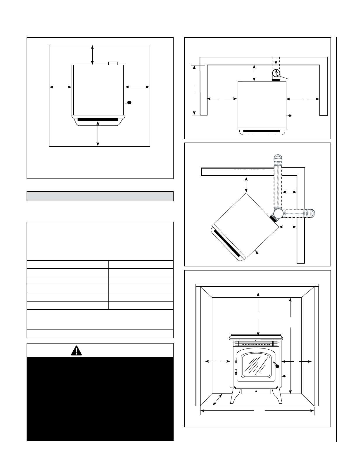
Up to * 6”(153mm)
minimum
Rear Wall or Alcove - Clearance to Combustibles
Combustible
6”
(153mm)
minimum
6” (153mm)
Floor Protector
*Note: When installed at clearances less than 6”, floor protection is only required
to extend to the wall. Refer to Page 4 for chimney/venting floor protection
requirements and recommendations.
minimum
6”
(153mm)
minimum
Figure 1 - Floor Protection Requirements
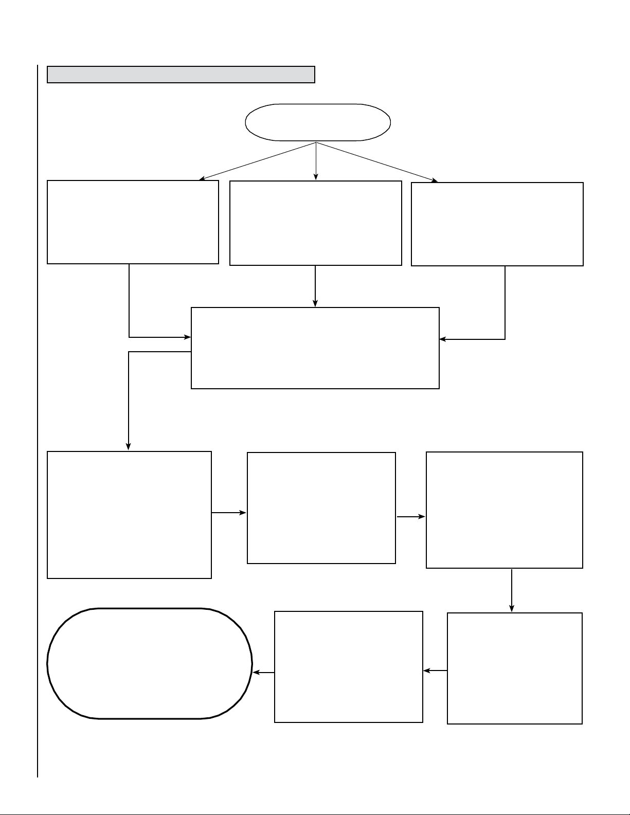
CLEARANCES
Standard residential or manufactured home installation. These appliances
require the following minimum clearances to combustibles.
MINIMUM CLEARANCES TO COMBUSTIBLE MATERIALS
NE PAS ENLEVER CETTE ÉTIQUETTE DÉGAGEMENT MINIMUM POUR LES
MATÉRIAUX COMBUSTIBLES
Freestanding Stove Installation / Installation Du Poêle Autonome
Manufactured (Mobile) Home Or Residential Installation / Installation Résidentielle
Ou Dans Une Maison réfabriquée (Mobile)
A - Sidewall to unit 4” / 102 mm
B - Backwall to unit 1” / 25 mm
C - Sidewall to unit Corner 1” / 25 mm
D - Max. Depth of Alcove
E - Flue to Wall
F - Ceiling Height above stove top 21-1/2” / 522 mm
u
· Alcove Measurements (see Figure 4): Height, Minimum – 49” (1245
mm), Width Minimum – 32” (813 mm), Depth Maximum – 24” (610 mm)
24” / 610 mm
u
3" / 76mm
v
v See vent manufacturer to verify clearances
Table 1
B
D
A
Combustible
Figure 2
Corner - Clearance to Combustibles
Combustible
C
Figure 3
Rear Wall or Alcove - Clearance to Combustibles
F
E*
E*
C
49”
Min.
A
Combustible
Combustible
IMPORTANT
•
Minimum clearances specified may not allow
for ease of operation and maintenance (please
take this in to account when planning the instal
lation). If installed to the minimum clearances,
removal of the appliance may be necessary for
servicing.
•
Recommended clearance zone from the front of the
appliance to combustibles is 4 feet minimum.
•
Clearances to combustibles for the appliance
can only be reduced by means approved by the
regulatory authority.
A
A
-
24”
Max.
32”
Min.
Figure 4
*Note: Refer to pipe Manufacturer's installation instructions for minimum
pipe clearances.
5
INSTALLATION TIPS
INSTALLATION TIPS
Select Your Installation Type
GOOD INSTALLATION *
Horizontal Installation
(Direct Vent - Outside Wall)
No natural draft. Wind
pressures may affect operation
REQUIRES 3”
DIAMETER STANDARD
BETTER INSTALLATION
Vertical and Horizontal Installation
(Up and Out)
Some natural draft aids venting. Wind
pressures may still affect operation
Natural draft improves operation and
VENTING TYPE
a: PL-Vent Pipe / Pellet Vent (w/stainless inner liner)
b: Stainless Steel flex liner may be used inside existing flue
or chimney (woodstove replacement applications)
CAUTION: Do not use Type B-Vent Pipe
MANUFACTURED
HOME
BEST INSTALLATION
Vertical Installation
(Straight Up)
negative effects from wind
CLEARANCES TO
COMBUSTIBLES
PL-VENT / PELLET PIPE
With listed termination kit. If
installation requires in excess of
11’ of pipe, it is recommended a
4” diameter pipe be used.
Requires outside air for com-
bustion. Use a galvanized or
stainless steel pipe for duct.
Minimum duct size 1-5/8” dia.
Ensure all clearances are maintained in accordance to instruc-
tions contained on product
safety label and in compliance
with pipe/venting requirements.
POWER SUPPLY
PLEASE REVIEW THIS ENTIRE
INSTALLATION AND OPERA-
TION MANUAL FOR ADDITIONAL
INSTRUCTIONS.
* In horizontal vent installations It is recommended that when an appliance is vented directly through a wall, a minimum of 6 feet (1.83 M) of vertical pipe is
installed to create some natural draft. This will reduce the possibility of smoke or odor entering the dwelling during appliance shutdown or loss of power.
6
Must have proper polarity and
be grounded.
Note: Use of an extension
cord may adversely effect the
performance of your unit.
Seal All
Venting Joints:
Use RTV
(high temp silicone)
MANUFACTURED HOME INSTALLATION
In addition to the standard installation instructions, the following instructions may be required by local, state or federal building codes:
• Installation should be in accordance with the Manufactured Home and
Safety Standard (HUD), CFR 3280, Part 24.
• The stove must be permanently bolted to the floor using four 1/4" Lag
screws. The lag screws must be an adequate length to extend through
the hearth pad and into the floor as shown in Figure 5. Install the lag
screws as shown in Figure 5. A minimum of two lag screws must be
used.
•
Connecting the Cascade™ stove to outside combustion air is required
in manufactured home installations and when required by local building
codes. An outside air inlet must be provided for combustion and be
unrestricted while unit is in use. Use a galvanized or stainless steel
pipe for the duct (the outside air inlet on the stove is 1-5/8” diameter).
The air intake on the exterior of the home should always be located
a minimum of 18" below the flue termination. The Inlet shall remain
free of obstruction while unit is in operation and constructed in a
manner so as to prevent material from dropping into the inlet or into
the area beneath the dwelling. The inlet shall also have a screen with
openings not larger than 1/4" to prevent rodents from entering.
• Stove must be permanently electrically grounded to the steel chassis
of the manufactured home using a 8 GA copper wire and a serrated
or star washer (to penetrate paint or protective coating to ensure
grounding). The location selected for ground attachment to the stove
must be dedicated for this purpose. Grounding must comply with
NFPA-70-latest edition standards, CSA C22.1-latest edition in Canada,
as well as any local codes.
• See Pages 9 through 16
ments.
•
WARNING: DO NOT INSTALL THIS STOVE IN A SLEEPING ROOM IN
A MANUFACTURED HOME.
•
CAUTION: THE STRUCTURAL INTEGRITY OF THE MANUFACTURED
HOME FLOOR, WALLS, CEILING/ROOF MUST BE MAINTAINED.
for additional information on venting require-
Manufactured Home Exhaust Vent Pipe Installation Guidelines
This stove is approved for venting with Type L and Type PL pellet vent
pipe listed to UL 641 and ULC S609. We recommend the use of venting products manufactured by Security Chimneys International. The
pipe should extend at least 3 feet above the part of the roof through
which it passes. The top of the pipe should be at least 2 feet above the
highest required elevation of any part of the manufactured home within
10 feet of the pipe (see Page 12, Manufactured Home Chimney Height
Requirements).
If the exhaust vent exits the manufactured home at a location other than
the roof, and exits at a point 7 feet or less above the ground level on which
the manufactured home is position a guard or method of enclosing the
pipe shall be provided at the point of exit for a height of up to 7 feet. The
openings, if any, in this guard shall not allow a 3/4” rod to pass through.
A 1/2” rod could pass through but should not be able to touch the pipe
when inserted through the opening a distance of 4 inches.
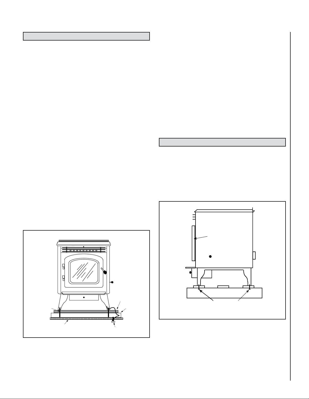
INSTALLATION
Removing Appliance From Pallet
1. After removing the packaging from the stove, lift the hopper lid, and
remove any pre-packaged items that were shipped in the hopper. Also
open the door assembly and remove any pre-packaged items.
2. Using a 1/2" socket or open end wrench, remove the four nuts from
inside the stove legs that secure the stove to the pallet braces.
Figure 5
Bolt
Chassis
Floor
Protector
Floor
Grounded to Steel
Chassis
NOTE: DIAGRAMS & ILLUSTRATIONS ARE NOT TO SCALE
Figure 6
Front
Door Assembly
Back
Pallet
Bolt locations
Remove 4 nuts inside stove legs.
7
Installation Check List
It is strongly recommended that you have an authorized Lennox Hearth
Products dealer install your stove. If you install your stove yourself, you
should review your installation plan with an authorized Lennox Hearth
Products dealer.
Check list:
Check off each item as you proceed with the installation process.
qRead the ENTIRE stove installation section first.
qDetermine the appropriate measurements and locations for your
installation.
qFollow the general installation directions under Installation.
qBe sure to pre-fit all items before you install, fasten, or set up the
stove permanently.
qMeasure for exhaust (also outside air tube when applicable) and mark
the location. Place the unit in place to make sure it's correct before
cutting holes in your wall.
Prior to lighting your appliance:
qReview the Important Warnings section (see Page 2).
qReview Fuel Specifications (see Page 19).
qReview and follow instructions in the Care and Operation Section (see
Pages 17 through 19
).
qPlug power cord connector into corresponding connector on the back
of appliance.
After you have begun operation of your appliance:
q Review the routine cleaning / maintenance information.
q Enjoy the warmth from your new Lennox Hearth Products pellet appli-
ance!
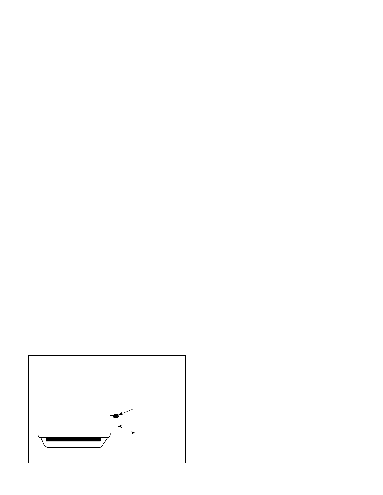
Damper Location and Adjustment
The damper is a plate that helps control the amount of airflow supplied
for combustion. With the damper pulled out all the way, the airflow is
at its maximum. As the damper is pushed in, the amount of air that is
allowed to flow is reduced.
It is very important to preset your damper prior to burning your pellet
stove. The damper rod is located on the right side of the stove as shown in
Figure 7
. The damper should be pulled all the way out to the full open
position during initial operation. It may need to be manually adjusted
inward depending on the type of pellet fuel being burned. Adjust in 1/4”
increments until optimum combustion air flow is achieved. The damper
control adjusts the amount of combustion air to the UltraGrate™. When
the damper has been correctly adjusted, you will observe a brisk, yellowto-whitish flame. Fuel should not “pile-up” in the grate. The proper air
settings will vary from stove to stove due to installation, altitude, and
the fuel being burned.
Initial Setting - Pull damper
out to the full open position,
then adjust in 1/4” increments
until optimum combustion air
flow is achieved.
Top View of Stove
Damper Rod
Front
Push in for less air
Pull out for more air
Figure 7 - Damper Control
It will be necessary to monitor the appearance of the flame during the first
4-8 bags of pellets. If the flame is smoky red or orange with evidence of
soot at the top of the flame, the damper will need to be adjusted to deliver
more combustion air (see Figure 7). If the flame is “short” at the higher
burn rates and appears to burn the pellets out of the UltraGrate™ faster
than they can be resupplied, or there are significant variations of flame
height within a single burn setting, the damper may need to be adjusted
to deliver less combustion air.
After the damper is adjusted, re-evaluate the appearance of the flame. It
may be necessary to continue adjusting the damper in increments until
proper combustion is achieved (the flame should become a brighter
yellow and begin to “dance”).
Once the damper has been properly set, and if the routine maintenance
is performed as needed, the damper should not require re-adjustment
unless you are changing from a premium grade pellet to a standard or
high ash pellet, in which case the damper may need to be moved outward
to help prevent the accumulation of ash in the UltraGrate™.
Damper Adjustment Guideline
Lack of Combustion Air: By opening the damper, this will increase com-
bustion air delivery. Symptoms of insufficient combustion air include;
unburned fuel, lazy smoky or red / orange flame, excessive ash or soot,
excessive buildup on glass, fuel may “pile-up.“
Contributing factors:
• High Altitude – Lack of oxygen
• Restrictive Venting (elbows, horizontal runs, cold external
chimneys, etc.).
• Dirty / Poor Quality Fuel.
• Lack of Maintenance
Note: Excessive amounts of Fly-ash built-up in the grate, clinkers in the
grate or leakage of air (if the grate is not properly seated) will starve
the fire for air. See Routine Maintenance, on Pages 20 through 24 for
information on cleaning requirements.
Excessive Combustion Air: Adjusting the damper to a more closed position will reduce the combustion air delivery. Symptoms of excessive air
include; fuel burns too quickly (results in smoking or smoldering pellets),
white to yellow flame, etc. If the damper is open too far, the burning pellets
will lift off the grate and fly up into the air much like popping corn does.
Another flame characteristic of a damper that is open too far is a flame
that has significant variation in height on any single burn setting.
Note: Excessive combustion air reduces efficiency.
Contributing factor:
•· Venting system providing excessive draft.
• Dry, hot burning fuel
Correct Combustion Air / Proper Burn Characteristics: When the damper is
correctly set, the burning pellets should move (wiggle) around slightly and
the flame should be bright yellow and stay at relatively even height.
Outside Air Installations
Connecting the Cascade™ pellet stove to outside combustion air is
optional, except in manufactured (mobile) home installations and when
required by local building codes. The stove’s air intake will accept 1-5/8”
ID pipe to accommodate outside air installations. The air intake on the
exterior of the home should always be located a minimum of 18" below
the flue termination and must remain free of obstruction. The inlet must
also have a screen with openings not larger than 1/4" to prevent rodents
from entering.
8

VENTING REQUIREMENTS
It is recommended that only an Lennox Hearth Products dealer install your
pellet stove. The specified installation requirements must be followed to
ensure conformity with both the safety listing of the appliance and local
building codes. All clearances, installation instructions and precautions
specified by the vent manufacturer must be followed.
Offsets
In every installation, a single or double clean-out “tee” is recommended
for every ninety-degree offset (this tee will help collect ash residue and
will allow for routine cleaning without the need to disconnect sections
of pipe).
Pipe Clearances/Requirements
Selecting a Location
Review the appliance clearance requirements before installing the
venting system (see Page 5). Position the appliance far enough away
from walls to allow adequate room for servicing. Choose the appliance
location with the least amount of interference with the house framing,
plumbing, wiring, etc.
Preferred Vent Configuration
For the best performance, we recommend a vent run design which runs
vertically and terminates above the roof line. This design will allow natural
draft to improve the flow of flue gases and will aid in combustion and
stove performance.
Type of Pipe
This stove is approved for venting with Type L and Type PL pellet vent
pipe (sometimes referred to as “L-Vent pellet vent”, listed to UL 641 or
ULC S609). We recommend the use of venting products manufactured by
Security Chimneys International. Connect the pellet vent pipe or the “tee”
to the flue collar using a minimum of three screws and seal as specified
in “Pipe/Liner Joint Requirements” on this page. Do not use class B gas
chimney or single wall chimney as a substitute.
Size of Pipe
These pellet appliances are approved for use with the following vent sizes:
3” (75 mm) standard, or 4” (100 mm), see Page 13 - for determining
correct size vent. When 4” pipe is used: for horizontal vent installations
use a 3” (75 mm) to 4” (100 mm) adapter - available from vent manufacturer. For vertical installations use a 3” (75 mm) to 4” (100 mm) “tee”
- available from vent manufacturer.
See pipe manufacturers instructions for installation of venting components
and clearances. Follow pipe manufacturers installation precautions for
passing pipe through a combustible wall or ceiling (i.e. use an approved
thimble).
Notes
• Offsets and horizontal runs accumulate fly-ash and soot which reduces
the exhaust flow and performance of the stove.
• Total Offsets in venting system should not exceed 270° total in direc
tion change.
• Maximum Vertical Vent - 30 feet (9.14 M)
• Horizontal Runs - The maximum total horizontal run must not exceed
10 feet (3.1 meters).
• Horizontal run of pipe requires 1/4” (7 mm) rise per foot.
• Pellet vent pipe requires 3” (75 mm) clearance from outside of pipe
unless otherwise specified by vent manufacturer - all diameters: 3” (75
mm) and 4” (100 mm). A support bracket must be installed every 4
feet (1.2 m) of pellet vent pipe on the exterior wall of the house unless
otherwise specified by vent manufacturer.
• It is not recommended to terminate exhaust vent on the prevailing
wind side of the house.
• In Canada, where the venting may pass through a wall, or partition
of combustible materials, the installation shall conform to CAN/CSAB365. When installing the wall thimble and other venting components,
follow the vent manufacturers instructions. Maintain an effective
vapor barrier at the location where the chimney or other component
penetrates to the exterior of the structure.
-
NOTE: DIAGRAMS & ILLUSTRATIONS ARE NOT TO SCALE
9

Pipe/Liner Joint Requirements
Vent Termination
Silicone sealant and three screws are required to secure the first vent
connection to the appliance flue collar. Secure and seal the remaining
vent sections per the vent manufacturers instructions. ALL horizontal
joints must be sealed gas-tight (air tight, sealed connection). Use RTV
high temperature silicone or Interam, if necessary, to provide a complete
seal between vent sections.
Connection to Masonry Chimney through a Wall
Be sure to verify the construction of a masonry chimney, as it may have
combustible framing.
Approved liner when relining Masonry or Factory Built Fireplaces is
2100HT (degree F.) liner listed to UL 1777 or ULC S635.
Connection to an Existing Class A Chimney
A chimney adapter can be used to make the connection from 3” (75
mm) or 4” (100 mm) pellet vent pipe (listed to UL 641 or ULC S609) to
existing UL chimney system. Verify with the pipe manufacturer that your
pipe brands will interconnect.
Horizontal Vent Installations
On all horizontal vent installations (short, horizontal runs with no vertical
pipe); care should be taken when choosing a location for terminating the
vent. It is not recommended to directly vent the exhaust on the prevailing
wind side of the house. It is recommended that when an appliance is
vented directly through a wall, a minimum of 8 feet (2.5 m) of vertical
pipe should be installed to create some natural draft. This will reduce
the possibility of smoke or odor entering the dwelling during appliance
shutdown or loss of power.
Do not terminate vent in an enclosed or semi-enclosed area such as:
carports, garage, attic, crawl space, under a deck, porch, narrow walkway,
closely fenced area, or any location that can build up a concentration of
fumes such as a stairwell, covered breezeway etc.
Vent surfaces can get hot enough to cause burns if touched. Adults
should supervise children when they are in the area of a hot stove.
Non-combustible shielding or guards may be required.
Termination Cap
The termination of the outside chimney of the pellet stove shall be located
in accordance with the following:
A. Higher than 3 feet (.92 m) above any forced air inlet (air conditioner,
etc.) located within 10 feet (3 m).
B. Not less than 4 feet (1.2 m) below, 4 feet (1.2 m) horizontally from or
1 foot (3.1 m) above any gravity air inlet (door, window, etc.) which
flue gases could reenter the dwelling.
C. Not less than 2 feet (.6 m) from combustible materials such as an
adjacent buildings, fences, protruding parts of the structure, roof
overhang, plants and shrubs, etc. and not less than 7 feet (2.1 m)
above grade when located adjacent to the public sidewalks (access).
The final termination of the exhaust system must be configured so that
flue gases do not jeopardize the safety of people passing by, overheat
combustible portions of nearby structures or enter the dwelling.
D. Not less than 3 feet (.92 m) below an eave (maximum overhang of 3
feet (.92 m) or any construction that projects more than 2” (51 mm)
from the plane of the wall.
E. The distance from the bottom of termination to grade is 12” (305 mm)
minimum. This is conditional upon plants and nature of grade surface:
Be careful to choose a location for the vent termination which does
not expose people or shrubs to high heat from the exhaust gases.
The exhaust gases are not hot enough to ignite grass, plants and
shrubs located in the vicinity of the termination although they should
be a minimum of 3 feet (.92 m) away. The grade surface under the
termination must not be a lawn.
F. Since sparks may escape from the exhaust pipe of any stove, use
caution when positioning the vent pipe. Refer to pipe manufacturer’s
instructions when installing and terminating the exhaust. The vent pipe
should be horizontal and never run the pipe in a downward direction
(recommend a 1/4” [7 mm] rise per foot horizontal).
10
NOTE: DIAGRAMS & ILLUSTRATIONS ARE NOT TO SCALE
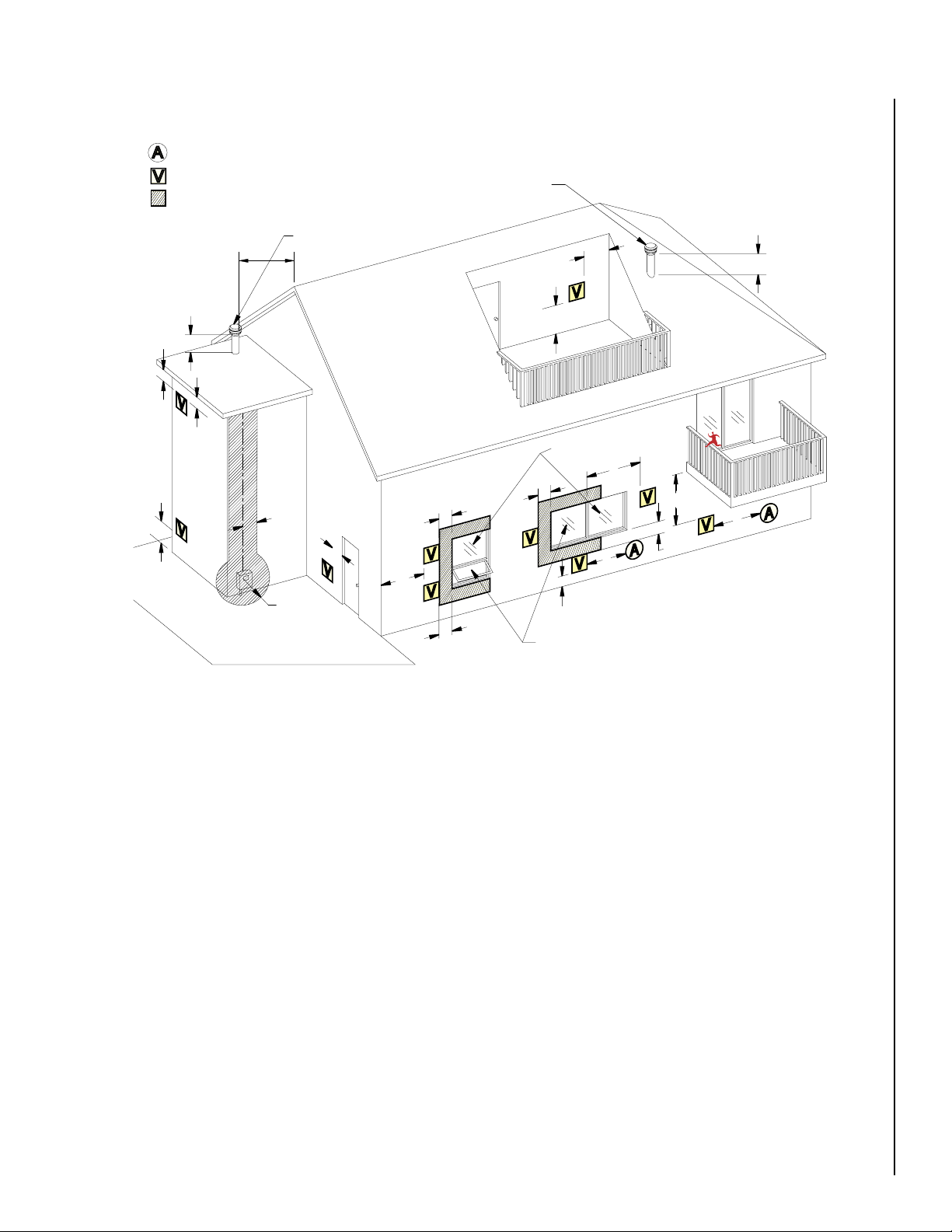
Vent Termination Locations
Vent Terminal
Area Where Terminal Is Not Permitted
(From Eave)
Vertical Terminal
Vertical Terminal
Fixed Closed
Able To Open
A
A
B
B
B
B
C
D
E
F
G
H
J
K
L
M
N
24”
(610mm)
B
Air Supply Inlet
24”
(610mm)
A = Clearance above grade, veranda, porch, deck, or bal-
cony (min. 12”/30cm)
B = Clearance to window or door that may be opened (min.
12”/30cm above - 48”/1.2m below and to the side)
C = Clearance to permanently closed window *(min.
D = Vertical clearance to ventilated soffit located above
12”/30cm)
the terminal within a horizontal distance of *(min.
24”/60cm) from the centerline of the terminal (min.
22”/55cm) check with local code.
E = Clearance to unventilated soffit *(min. 12”/30cm)
F = Clearance to outside corner *(min. 12”/30cm)
G = Clearance to inside corner *(min. 12”/30cm)
H = Not to be installed above a meter/regulator assembly
within *(min. 36”/90cm) horizontally from the center-
line of the regulator.
J = Clearance to service regulator vent outlet *(min.
72”/1.8m)
K = Clearance to non-mechanical air supply inlet to build
ing or the combustion air inlet to any other appliance
Figure 8
*(min. 48”/1.2m)
L = Clearance to a mechanical air supply inlet *(min.
120”/3.1m)
M = **Clearance above paved sidewalk or a paved driveway
located on public property *(min. 84”/2.1m)
N = ***Clearance under veranda, porch, deck, or balcony
(min. 12”/30cm)
Note:
* Local codes or regulations may require different clear
ances.
** A vent shall not terminate directly above a sidewalk or
paved driveway which is located between two single
family dwellings and serves both dwellings.
*** Only permitted if veranda, porch, deck, or balcony is
NOTE: DIAGRAMS & ILLUSTRATIONS ARE NOT TO SCALE
-
fully open on a minimum of two sides beneath the
floor.
-
11

Chimney Height Requirements - Site Built Residential Home
Less than
10 Feet (3 m)
10 Feet
(3 m)
3 Feet (914 mm)
Minimum
2 Feet (610 mm) Min.
3 Feet
(914 mm)
Min.
m = meter
mm = millimeter
The vent termination height required is - USA, 1-foot minimum; Canada
3-feet minimum above the roof penetration point as illustrated below
(Ref. USA - National Standard, NFPA 211 and Canada National Standard
CSA B365-01). Check with your local building official for additional
requirements for your area.
To pass inspection in nearly any jurisdiction, the chimney must meet both
safety and exhaust flow requirements. The (3’ by) 2’ by 10’ rule applies
to both masonry and factory built chimneys
* Ref. USA - National Standard, NFPA 211-latest edition and Canada
National Standard CSA B365-01-latest edition. Vents installed with a
listed cap shall terminate in accordance with the terms of the cap’s
listings.
Termination Cap
Must Be Listed To
UL 641 or ULC S609
USA 1 Foot Minimum
CANADA 3 Feet Minimum
*Min. 2 ft. clearance
is required to comTermination height is
measured above the
highest point where
it passes through the
roof surface.
bustibles (i.e. cedar
shake roof, etc.)
Figure 9 - Site Built Residential Home Chimney Height Requirements
Chimney Height Requirements - Manufactured Homes
The chimney must extend 3’ (.92m) above the level of roof penetration
and a minimum of 2’ (.61m) higher than any roof surface within 10’
(3m) (see below). Check with your local building officials for additional
requirements for your area.
Requires A Listed Termination Cap *
Top Of Flue Must Be 2’
Higher Than Any Part Of
Roof Within 10’ Horizontal
Top Of Flue Must Be
3’ Higher Than Highest Point Of Roof
Penetration
Termination When Connected to Masonry Chimney or Existing
Class A Chimney
A flexible corrugated chimney liner has much greater resistance to the
flow of flue gases than does a rigid liner. For this reason we recommend
that a larger, 4” liner be used on vertical runs exceeding 15 feet or that
rigid venting be used . See Figure 11.
If a flexible corrugated chimney liner is used, it must be fully extended
to eliminate any sagging and to improve the exhaust flow.
Listed Pellet Vent
1’ Section of PL Vent
(listed to UL 641 or
ULC S609)
3” or 4” liner
(listed to UL 1777
or ULC S635)
Termination Cap
Chase Cover
Termination When
Connected to Masonry
Chimney or Existing
Class A Chimney
Figure 11 - Existing Chimney Termination
Figure 10 - Manufactured Home Chimney Height Requirements
12
NOTE: DIAGRAMS & ILLUSTRATIONS ARE NOT TO SCALE

Determining Size Of Pipe To Install
A
E
F
H
G
B
C
D
To determine what diameter pipe to use in an installation (3” or 4”), first
find the “equivalent pipe length” using the following guidelines, then plot
the number and the altitude on the installation chart (Figure 12).
30
4" Diameter Only
20
Fill out the installation chart, and calculate your total equivalent pipe
length. After you have the total equivalent pipe length, use the Pipe
Selection Chart (Figure 12) to determine if your installation requires 3”
or 4” exhaust pipe.
Installation Chart
Type of Pipe # of Elbows or
Feet of pipe
90° Elbows /
Tee (A & G)
45° Elbows
(C)
Horizontal
(B & F)
Vertical(E) x .5 Ft. (.15m)
Equivalent Feet Total Equivalent
Feet
x 5 Ft. (1.5 m)
x 3 Ft. (1 m)
x 1 Ft. (.3m)
Table 2
Sample Installation Chart
Type of Pipe # of Elbows or
90° Elbows /
Tee (A & G)
45° Elbows
(C)
Horizontal
(B & F)
Vertical (E) 8 x .5 Ft. (.15m) 4 (1.2m)
Total Equivalent Feet = 20
Feet of pipe
2 x 5 Ft. (1.5 m) 10 (3m)
1 x 3 Ft. (1 m) 3 (1m)
3 x 1 Ft. (.3m) 3 (1m)
Equivalent Feet Total Equivalent
Feet
Table 3 - Sample Chart for Figure 13
3 or 4”
Diameter
10
Equivalent Pipe Length (Feet)
0
0
1
3
2
Altitude x 1000 Feet
4
Figure 12 - Pipe Selection Chart
NOTE:
All equivalent pipe styles
shown are standard for all freestanding models.
A- 90 Degree Elbow
B- 1’ Horizontal Pipe
C- 45 Degree Elbow
D- Standoff Braces
E- 8’ Vertical Pipe
F- 2’ Horizontal Pipe
G- 90 Degree Tee
H- Wall Thimble
6
5
7
9
8
10
Figure 13 - See Sample Installation Chart
NOTE: DIAGRAMS & ILLUSTRATIONS ARE NOT TO SCALE
13

Standard Horizontal Vent Installation
G*
D
A
B
C
E
F
A
D
Installing the Cascade™ Pellet Stove
This stove is approved for venting with Type L and Type PL pellet vent
pipe listed to UL 641 or ULC S609. We recommend the use of venting
products manufactured by Security Chimneys International.
1. Locate the proper position for the listed type “PL” wall thimble. Avoid
cutting wall studs when installing your pipe. Use a saber saw or keyhole
saw to cut the proper diameter hole through the wall to accommodate
the wall thimble. Use extreme caution to avoid cutting into power lines
within the wall of the home. The hole size will depend on the brand
of pellet vent that you are using. Install the wall thimble in the hole.
ALL INTERLOCKING PIPE CONNECTIONS MUST BE SEALED GAS-
2.
TIGHT AND SECURED TOGETHER PER VENT MANUFACTURER
INSTRUCTIONS.
Position the stove approximately 12” (305 mm) from the wall on the
floor pad. Push the “PL” pipe through the wall thimble. Squeeze a
bead of high temperature silicone (RTV) sealer around the end of the
machined portion of the 3” (76 mm) pipe connector on the back of
the stove. Firmly push on a section of “PL” pipe until inner pipe liner
pushes into the bead of RTV sealer.
3. Push the stove with pipe attached towards the wall (the pipe will go
through the wall thimble). Do not position the back of the stove closer
than 1” (25 mm) from the wall (see Clearances, Page 5).
4. Install listed type “PL” 45 degree elbow with rodent screen or cap on
outside end of pipe. The Inlet shall remain free of obstruction while
unit is in operation and constructed in a manner so as to prevent material from dropping into the inlet or into the area beneath the dwelling.
The inlet shall also have a screen with openings not larger than 1/4"
to prevent rodents from entering.
5. If the installation includes a source of outside combustion air; cut a
separate hole through the wall for the fresh air tube. This tube should
be 1-5/8” (42 mm) minimum diameter I.D., steel only. Connect outside
air pipe to air inlet on stove. This tube must be terminated with a 45
degree elbow or hood.
Notes:
•
Combustion air may also be drawn from a vented crawl space under
the home.
• All joints for connector pipe are required to be fastened together per the
vent manufacturers instructions. If vented horizontally, joints must be
made gas-tight (air tight, sealed connection) in a manner as specified
on this page (see instruction #2). INSTALL VENT AT CLEARANCES
SPECIFIED BY THE VENT MANUFACTURER.
• Greater back clearance will improve the ease of serviceability of the
stove.
• The end of the exhaust pipe must extend a minimum of 12” (305 mm)
from the outside of the building.
14
A. Use RTV Here
B. Quick Disconnect Fitting
C. 3”(75 mm) PL-Vent Pipe
D. Wall Thimble
E. Hole in Wall
F. 45 Elbow or End Cap
G. Combustion Air Inlet *
Figure 14 - Horizontal Vent Installation
Silicone sealant and three screws required on the first vent connection.
Secure and seal the remaining vent sections PER VENT MANUFACTURER INSTRUCTIONS.
NOTE: DIAGRAMS & ILLUSTRATIONS ARE NOT TO SCALE
12” (305 mm)
Min. From
Outer Wall
NOTE: Connect “C”to “F”
* Connect a Metal Fresh Air Pipe - OPTIONAL
(EXCEPT FOR MOBILE HOME INSTALLATIONS)
12”(305 mm)
From
Ground or Other
Surface

Standard Horizontal Installation Configurations
Corner Through the Wall
Top View Illustration
Wall
llaW
Outside
Air Intake
12" (305 mm)
Minimum From
Outer Wall
Corner Through the Wall
Top View Illustration
Horizontal Vent Through the Wall
Side View Illustration
Wall
llaW
1" (25.4 mm)
Minimum
12" (305 mm)
Minimum From
Outer Wall
45 Degree
Elbow
12" (305 mm)
From Ground or
Other Surface
6" / 152 mm
Minimum
Hearth Pad / Floor Protection
Outside
Air Intake
12" (305 mm)
Minimum From
Outer Wall
Model: Cascade
Maintain minimum clearances specified by
vent manufacturer between wall and pipe.
If you vent to the furthest wall, the vent pipe
must maintain the specified clearance parallel to the other wall.
®
Notes:
• It is not recommended to terminate
exhaust vent on the prevailing wind
side of the house.
Figure 15 - Corner Through the Wall
1” (26 mm)
Minimum
Outdoors
Note: Horizontal run of
pipe requires 1/4” (7 mm)
rise per foot.
Figure 16 - Parallel Through the Wall
NOTE: DIAGRAMS & ILLUSTRATIONS ARE NOT TO SCALE
15

Standard Vertical Installation Configurations
Model: Cascade®
This appliance may be connected to an existing flue or by installing
type “PL” vent pipe (listed to UL 641 and ULC S609). If a liner is run all
the way to the top of the existing chimney, the existing flue should be
sealed with a steel plate. Start a vertical run with a Tee at the back of the
stove. Other options are illustrated below. Note: See Vent Termination
Requirements on Pages 9 through 11.
Preferred Installation – Vertical Vent Through the Roof
This venting configuration allows for the best stove performance. The
vertical pipe promotes natural draft and with the chimney inside the
dwelling, the flue gases stay warm, thus rising at a consistent rate.
Note: See Pages 9 through 11 for Vent Termination Requirements.
Listed Rain Cap
Exterior
Vertical Vent
Vertical Vent
Into a
Masonry Flue
Optional Complete
Liner and Listed
Termination Cap
Maintain clearances
specified by vent
manufacturer
Listed Rain Cap
Wall Straps
Required Every
4 Feet Minimum
Maintain clearances
specified by vent
manufacturer
Figure 17
Listed Rain Cap
Optional
Clean-Out
Access Door
Vertical Vent
Through the
Roof
Maintain clearances
specified by vent
manufacturer
Interior
Vertical Vent
into an Existing Class A
Chimney
Flashing
Clean-Out
Tee
Figure 19
Listed Rain Cap
Existing
Chimney Pipe
Pipe Increaser
Extend Pipe to the Top
if Existing Chimney is
Corroded or Damaged
Maintain clearances
specified by vent
manufacturer
16
Figure 18
NOTE: DIAGRAMS & ILLUSTRATIONS ARE NOT TO SCALE
Clean-Out
Tee
Figure 20

CARE AND OPERATION
Simple Operating Instructions
1. Start
FIRST TIME USE
2. Preparation
a] Check hopper and remove
any materials from hopper
and auger
b] Check cast UltraGrate for
proper fit (ensure cast
UltraGrate is set securely in
the base - see Figure 22)
c] Check door gasket and door
latch to ensure tight seal
(see Figure 30)
d] Connect power cord to
grounded power supply
outlet
3. Priming the Auger
(Optional)
a] Fill hopper with pellets
Note: Use quality grade pellet
fuel
b] Move the "HEAT OUTPUT"
switch on the control panel
to the “HIGH HEAT” position
to activate the auger.
e] Wh en p el le ts begin to
drop from feed tube into
UltraGrate, turn switch to
"OFF"
4. Stove is now ready for
start-up
5. To Start Your Stove
a] Check hopper, and fill with
pellets, if necessary.
b] Place a small amount of an
approved (non-volatile) gel fire
starter on top of the pellets in
the UltraGrate. Using a match,
light the pellets. Close Door.
b] Turn the "HEAT OUTPUT"
switch to the "LOW HEAT"
setting.
The convection blower will be
activated when the HEAT OUTPUT
switch in on low or high.
6. Pellets will drop into
UltraGrate and stove will
light in approximately 3
to 7 minutes
Does the Stove Light?
Yes
7. The stove will enter "heat-
ing" mode and run at the
chosen setting
8. After approx. 5 minutes
adjust damper if necessary to obtain a bright
vibrant flame.
Notes:
• If the damper is too far
inward the flame will be
lazy/sooty and the fuel will
pile up in the UltraGrate
(see Page 8).
• If the damper is too far
outward the flame might
burn erratically.
Se e Pa ge 8 for fur ther
instructions on adjusting
the damper.
Heat Output
Auger On Indicator
No
7a. Follow the troubleshooting
section in this manual
Does the Stove Light?
No
Contact your Lennox Hearth
Products dealer for further
assistance
9. To Turn Off Pellet Stove
a] Turn the "HEAT OUTPUT"
switch to the "OFF" position.
Yes
b] Stove goes into cool-down
mode. Pellets stop feeding
and the fire goes out within
2 minutes after the auger
is shut off, the room air
blower and exhaust blower
will automatically shut off in
approximately 15 minutes.
10. Thank you for purchasing a Lennox
Hearth Products Pellet Stove
END
NOTE: DIAGRAMS & ILLUSTRATIONS ARE NOT TO SCALE
17

Control Board
Heat Output Switch - The Heat Output switch activates both the con-
vection and combustion blowers and the auger motor. If the exhaust
does not reach operation temperature within 25 minutes, the stove will
automatically shut down. If this occurs, repeat the lighting procedure
(pre-lighting instructions).
“OFF” position - The “Off” position on the Heat Output switch will turn
the stove off by turning off the auger motor. The remaining fuel in the
grate will safely burn up. Once the stove has cooled sufficiently the
blowers will shut off automatically.
“HIGH HEAT” position - The “High Heat” position on the Heat Output
switch will increase the fuel feed rate and blower speed for maximum
heat output.
“LOW HEAT” position - The “Low Heat” position on the Heat Output
switch will decrease the fuel feed rate and blower speed.
Auger “On” Light - The red L.E.D. light on the control panel indicates
when there is power to the auger motor. Under normal operation, this
light will blink on and off.
Fuel Feed Trim Control - The fuel feed trim control on the control panel
should be used when the damper control will not correct a poor combustion problem. Turning the trim control counter clockwise will decrease
the amount of fuel entering the UltraGrate™ and turning the trim control
clockwise will increase the amount of fuel entering the UltraGrate. The
trim adjustments compensate for fuel differences. Factory set “ON” time
is 1.9 seconds. The trim range is 1.6 to 4.5 seconds. Factory “OFF” time
for low is fixed at 4.2 seconds and for high it is fixed at 2 seconds.
Note: This control board is not thermostat or igniter capable.
Heat Output
Auger On Indicator
Fuel Delivery Rate
Feed
Rate
Setting
Low = 1.9 on / 4.2
High = 1.9 on / 2
Auger Motor
ON/OFF
Time
(seconds)
off (+/- 5%)
off (+/- 5%)
Auger “ON
Time” Trim
(seconds)
1.6 to 4.5
seconds
1.6 to 4.5
seconds
* Lb.’s per
hour fuel
delivery
1.5 Lb.’s
/ hr.
3.5 Lb.’s
/ hr.
**Approximate BTU
per hour fuel
delivery
12,600 BTU
/ hr
30,000 BTU
/ hr
Burn
Time
(hours)
40
17
Table 4
Initial Start-up / Empty Hopper Or Feed Tube:
During an initial start-up, or in the case where the hopper has run out of
fuel, it will be necessary to prime the auger feed system.
To prime the auger feed tube:
1. Ensure all packing material and foreign objects are removed from the
hopper. Fill the hopper with recommended pellet fuel and plug the
stove into the wall outlet.
2. Move the Heat Output switch on the control panel to the “HIGH HEAT”
position to activate the auger and blowers.
3. Look through the combustion chamber door and when you can see
the first pellets dropping into the grate, the auger is fully primed. This
will take up to 10 minutes.
Starting Your Pellet Stove
1. After the auger is fully primed, adjust the Heat Output switch to the
“OFF” position.
2. Place a small amount of an approved (non-volatile) gel fire starter on
top of the pellets in the UltraGrate (if chips are used as firestarter, place
chips in UltraGrate first then place pellets on top). Consult with your
authorized Lennox Hearth Products dealer for approved fire starting
products). DO NOT USE FLAMMABLE LIQUIDS TO START YOUR
STOVE.
3. Light the fire starter in the UltraGrate with a match and close the door.
4. After approximately 10 seconds, move the Heat Output switch on the
control panel to the “LOW HEAT” position. You will notice that the fire
will become active and there will be air coming from the Heat Exchange
Tubes and pellets will now begin to feed into the UltraGrate.
5. After the fire is burning well, adjust the Heat Output switch to the
desired setting. Adjust the damper control if necessary for proper
combustion. Look for a brisk, bright yellow to whitish flame.
Remember, different brand fuels feed at different rates.
Figure 21 - Control Board
Fuel Delivery Rate
The feed rate switch manages the fuel delivery rate by controlling the
amount of time the auger motor will run as follows:
* Feed rates are approximations only. Actual feed rate will vary depend-
ing on size, quality and length of fuel used and variations in line voltage.
** Estimated heat input based on fuel value of 8,400 BTU per lb. of
fuel.
Note: It is normal for some ash to build up on the inner glass surface at
the lower burn settings.
18
Turning Off Your Stove
Move the Heat Output switch to the “OFF” position. This will stop the
fuel feed and any remaining fuel in the grate will safely burn up. The
blowers will continue to run until the stove has cooled off sufficiently
and will then shut off automatically.
WARNINGS
• Never empty pellets from the Burn-Pot into the hopper.
Pellets that may appear to be cool may retain enough
heat to ignite other pellets resulting in smoke or fire
damage.
• DO NOT OVERFIRE THIS STOVE. This may cause
serious damage to your stove and void your warranty.
It also may create a fire hazard in your home. IF ANY
EXTERNAL PART OF THE UNIT BEGINS TO GLOW, YOU
ARE OVERFIRING. Immediately slide the knob to the
"OFF" position on the control board.

Filling the Hopper
To fill the hopper when stove is off:
FUEL
1. Lift the hopper lid to it's full opened position.
2. Fill the hopper with pellets.
3. Check to make sure there are no remaining pellets on top of the
hopper that may prevent the hopper lid from fully closing.
4. Close Hopper lid.
To fill the hopper when stove is in operation:
1. Repeat steps 1 thru 4 above.
2. When finished, check the red Auger “On” Light on the control panel
to verify that the stove is still in normal heating mode. The Auger
“On” Light indicates when there is power to the auger motor. Under
normal operation, this light will blink on and off.
3. If the Auger “On” Light on the control panel is off, the hopper lid
has been open too long and unit has gone into shut-down mode. To
relight, follow lighting instructions on Page 17.
Caution: Failure to ensure pellets in the UltraGrate remain
burning after re-fueling may result in smoke escaping from
the unit.
Lighting
Follow instructions on Page 17.
Automatic Safety Features
Power Outage: During a power outage, the stove will shut down safely.
It will not automatically restart when the power is restored. However, a
momentary power interruption may not shut your stove down.
A small amount of smoke may leak from the top of the window glass,
the hopper and from the combustion air intake, if the stove is vented
horizontally with no vertical pipe. This will not persist for more than 3
to 5 minutes and will not be a safety hazard. It may set off your smoke
alarm. To re-light the stove, follow the normal procedure for starting
your stove.
CAUTION
The use of unapproved, dirty, wet and / or high salt
content fuel will void the warranty!
Fuel Specifications - Using the Ultragrate™ burn system, this appliance
has been designed to burn wood residue pellets only (with up to 2% ash
content). Agricultural pellets (i.e. corn, alfalfa etc.) are not permitted to
be burned in the stove. Dirty fuel will adversely affect the performance of
the stove. The pellet fuel should meet P.F.I. (Pellet Fuel Institute) standards
for standard grade or premium grade residential pellet fuel. If the pellet
fuel meets these standards, it will be printed on the bag. Any questions
regarding pellet fuel can be answered at the Pellet Fuels Institute (PFI),
www.pelletheat.org.
Pellet Feed/Pellet Size - The pellet feed system is designed to handle a
wide range of pellet sizes up to a maximum of 5/16” diameter. Different
pellets may feed at considerably different rates. You may notice a difference in the burn if you change pellet fuel sizes. The longer the pellet, the
slower it will feed and vice versa. If the stove will not stay burning at the
minimum fuel feed setting, those particular pellets may not be feeding
fast enough. If this happens, reduce the amount of combustion air by
adjusting the damper. See Page 8 before adjusting the damper.
Clinkering - Silica (or sand) in the fuel, along with other impurities, can
cause clinkering. A clinker is a hard mass of silica formed in the burning
process. Clinkering is a function of the fuel, (not the stove), but adversely
affects the performance of the stove by blocking off the air passages in
the grate. Even P.F.I. approved pellet fuel may tend to clinker. A clinker
can be removed from the UltraGrate™ and placed in the ash pan with
the use of the grate scraper/ash pan tool furnished with your stove. See
Routine Maintenance (on Pages 20 through 24) for more information
on cleaning.
Note: If the area in which you live is prone to frequent power outages,
it is recommended that a minimum of 8 feet (2-1/2 meters) of vertical
vent pipe be included in the installation to induce a natural draft in the
event of a power outage.
Overheating: A high limit thermal switch will automatically shut down
the stove if it overheats. The stove will need to be manually re-lit. Allow
up to 45 minutes cooling time before re-lighting. If the overheating
continues, contact your authorized Lennox Hearth Products dealer for
more information.
NOTE: DIAGRAMS & ILLUSTRATIONS ARE NOT TO SCALE
19

Ash - The frequency of removal of the ash and maintenance performed
on the stove is directly proportional to the ash content of the fuel and the
operation duration of your pellet stove. Low ash fuel may allow longer
intervals between cleaning, however, a stove burning high ash fuel may
need to be cleaned as often as everyday.
Fuel Feed Rates - Different brands of pellets will feed at varying rates
due to their size and density (length and diameter). This may require a
slight adjustment in the damper control (see Page 8) or the fuel feed
trim to compensate (see Page 18).
Note:
See Fuel Delivery Rate on Page 18 for burn times.
PLEASE NOTE
facturing of pellet fuel and will not be held responsible for poor stove
performance or any damage caused by poor quality pellet fuels.
Pellet Fuel Storage -
•
Store your wood pellets in a dry place to prevent them from absorbing
excess moisture.
•
Do Not store your wood pellets within the clearance zone of the
stove.
•
Do Not store your wood pellets in a place that would block removal
of the ash pan or block access to refueling the hopper.
Wood pellets manufactured to the pellet fuels institute (P.F.I.) certification
standard are available in two grades, Standard and Premium. The primary
difference between the two is the ash content of the pellets.
The P.F.I. specification for standard grade and premium grade residential
pellet fuel is as follows:
• CHLORIDES (Salt): Less than 300 p.p.m. to avoid stove and vent
rusting.
• BULK DENSITY: 40 lb. / Cu. Ft. minimum
• MOISTURE CONTENT: 8% maximum
• ASH CONTENT:
(premium grade)
• FINES: 0.5% maximum through a 1/8” screen
• BTU CONTENT: There are a number of variations in pellet fuels that are
not included in PFI standards. For example, BTU (heat value) content
may range from just under 8,000 to almost 9,000 BTU, depending
upon species and region of the country and other variables.
: Lennox Hearth Products has no control over the manu-
< 2% maximum (standard grade) < 1% maximum
ROUTINE MAINTENANCE
IMPORTANT CAUTIONS:
• UNPLUG POWER CORD AND ENSURE APPLIANCE IS COLD
BEFORE PERFORMING ANY MAINTENANCE WORK.
• Some brands of pellets produce more ash and clinkers than
others. Therefore the frequency of performing the following
cleaning procedures depends to a great degree on the quality
of the pellets burned.
• Not cleaning this unit will cause it to burn poorly and will
void your warranty for this appliance.
• When removing ash build-up, use an approved ash vacuum
only. A cleaning brush can be used to loosen any ash build-up
before vacuuming. DO NOT USE A STANDARD HOUSEHOLD
VACUUM OR “SHOP VAC” AS THE FILTERS WILL LEAK THE
FINE PARTICLES OF ASH INTO THE HOME.
Notes
• Cleaning schedule will vary depending on quality of pellets used.
Burning high ash pellets will require more frequent cleaning.
• Using a drop cloth is recommended as some ash may spill onto the
floor during the cleaning process.
Cleaning
The following areas need to be inspected during routine cleaning:
•· UltraGrate™ (burn grate) (Homeowner)
•· Ash Slide Plates (Homeowner)
•· Ash Pan (Homeowner)
•· Heat Exchange Tubes (Homeowner)
•· Exhaust Passages and Vent Pipe (Qualified Technician Only)
• Gaskets (Qualified Technician Only)
• Window Wash (Homeowner)
• Cleaning Rear Stove Compartment (Qualified Technician Only)
• Blower Cleaning (Qualified Technician Only)
UltraGrate™ (Burn Grate)
Inspect the UltraGrate periodically so that the air holes don't clog with ash
or clinkers. The UltraGrate can easily be cleaned with the grate scraper
tool, or it can be removed. It is very important to monitor the ash build up
under the UltraGrate, as too much of ash will block combustion air from
entering the grate, causing pellets to pile-up in the grate. A clogged grate
will reduce the overall performance of the stove, cause dirty glass and
if not cleaned may lead to smoke escaping the stove. The ash build-up
under the grate is easily dumped into the ash pan by pulling out the ash
slides weekly (see Ash Slide Plate, Figures 23 and 25).
20
(Recommended Frequency
of 1 day – 7 days)
Figure 22 - UltraGrate
NOTE: DIAGRAMS & ILLUSTRATIONS ARE NOT TO SCALE

5
A
1
2
3
4
B
F
C
D
E
Cleaning UltraGrate™ and
Exhaust Passages
Grate Scraper and
Ash Pan Tool
UltraGrate
A, B: Exhaust
C, D: Ashslide Openings
E: 2. UltraGrate Housing
F: 2. Ash Pan
1,2: . Exhaust Passage
2. Access Plates
3,4: . Ash Slide Plates
5: 2. UltraGrate
Pellet Fuel Hopper
It is recommended to open the hopper lid by grasping it on the side as
shown in the following picture.
Open Hopper Lid by Grasping the Front Side
Be very careful not to touch other hot areas on stove!
Open hopper by grasping the front side, then lift
until it hinges back to the full open position.
Figure 24 - Hopper Lid
Ash Slide Plates
Ash that accumulates around the grate can be “dropped” into the ash
pan by simply opening the two ash slide plates. The ash slide plates are
located under the ash lip of the stove. Using the grate scraper / ash pan
tool, grasp each plate and pull it toward you. This will allow the ash to
dump or be swept into the ash pan below.
* (Recommended Frequency of 1 day – 2 weeks)
Figure 23
Cleaning Glass:
DO NOT CLEAN THE GLASS WHEN THE STOVE IS HOT.
CAUTION: Do not open the front door when the stove is hot. Clean the
glass using a soft cloth or paper towel and a household glass cleaner
or gas stove window cleaner. A commercial glass cleaner designed
for stoves is recommended. Do not use abrasive cleaners. A damp
cloth with a small amount of ash from the firebox can also be used
to clean the glass.
Servicing Glass
CAUTION: BE CAREFUL NOT TO ABUSE THE DOOR ASSEMBLY BY
STRIKING OR SLAMMING IT. IF THE DOOR ASSEMBLY OR GLASS IS
BROKEN OR DAMAGED, THEY MUST BE REPLACED BEFORE HEATER
CAN BE SAFELY OPERATED. USE ONLY COMPONENTS PROVIDED BY
THE MANUFACTURER AS REPLACEMENT PARTS.
Replacing Glass:
1. Remove door from stove by lifting door up and off hinge pins: Place
the door on a flat protected (towel) clean flat surface with the inside
of the door facing up. Remove the glass clips (by removing screws
holding clips), then carefully remove broken glass one piece at a time
(protective gloves are recommended).
2. Clean area where the glass with gasket will be installed.
3. Install new glass with gasket (use only factory 5 mm glass with glass
channel gasket. Do not substitute). Carefully reinstall glass clips. Be
very careful not to overtighten screws.
4. Reinstall door.
NOTE: DIAGRAMS & ILLUSTRATIONS ARE NOT TO SCALE
IMPORTANT NOTE: Make sure to fully close the plates when finished.
Failure to close the ash release slide plates completely may cause the
fuel to burn poorly (due to reduced air-flow through the grate), which
may then cause pellets to “pile up” in the grate.
Sweep ashes into
openings on sides
Ash Slide Plates
Ash Dump
(Recommended Frequency of 1 – 2 weeks)
Figure 25 - Cleaning Firebox With Ash Slide Plates
21

Ash Pan
Heat Exchange Tubes
Note: Periodically check for ash build up under the Ultragrate™. If the
ash is allowed to build up to the bottom of the UltraGrate™, there will be a
loss of combustion air and the pellets will start to pile up on the grate.
CAUTION: Disposal of Ashes - Ashes should be placed in a metal container with a tight fitting lid. The closed container should be placed on
a non-combustible floor or the ground - well away from all combustible
materials, pending final disposal. If the ashes are disposed of by burial
in soil or otherwise locally dispersed, they should be retained in the
closed container until all cinders have been thoroughly cooled.
(Recommended Frequency
of 2 days – 2 weeks)
Ash Pan
Figure 26 - Emptying Ash Pan
ENSURE STOVE IS COLD BEFORE CLEANING HEAT EXCHANGE
TUBES.
Remove Fly-ash from heat exchange tubes as follows:
1. Ensure the door is secured closed.
2. Open the hopper lid (see
Pellet Fuel Hopper, Page 21).
3. Using the hole in the handle of the grate scraper tool, “grab” onto the
heat exchange rake handle located above the door (in the center).
4. Pull the grate scraper tool back and forth several times (upward and
forward, then back) to rake a way Fly-ash from the heat exchange
tubes.
Note: If a more thorough cleaning of heat exchange tubes is desired, the
baffle plate in front of the tubes can be easily removed (slide baffle plate
forward until screw heads clear the notches on each side, then remove
baffle). With baffle plate removed, use a small brush to clean between
tubes (see Pages 22 and 32, item #3).
Note: The baffle plate should be removed at least once a year to allow
for a thorough cleaning.
WARNING
DO NOT USE BRUSH ON HOT STOVE
Removing Fly-ash from Heat Exchange Tubes
Soot and Flyash:
Formation and need for removal - The products of combustion will contain
small particles of flyash. The flyash will collect in the exhaust venting
system and restrict the flow of the flue gases. Incomplete combustion,
such as occurs during startup, shutdown, or incorrect operation of the
room heater will lead to some soot formation which will collect in the
exhaust venting system. The exhaust venting system should be inspected
at least once every year to determine if cleaning is necessary.
Exhaust Passages and Vent Pipe
Inspect frequently and clean when necessary. Fly-ash will accumulate at
all bends in the exhaust system.
Note: Large amounts of Fly-ash build-up will create a lack of combustion
air. Removing the Tee cap on vertical installations will allow an inspection
of the ash build-up in the exhaust Tee and will help you to decide how
frequently more extensive cleaning must be performed.
Heat Exchange
Tubes (close-up)
Rake Movement"
Heat Exchange
Rake Handle
Tube
Scraper
Recommended
Frequency of
2 days – 2 weeks
Figure 27 - Cleaning Heat Exchange Tubes
22

E
N
O
N
O
E
O
D
L
L
A
R
L
3
1
1
7
5
X9
4
0
3
L
5
1
1
7
X
9
4
0
1
1
1
1
L
O
E
N
P
O
R
Y
R
E
F
E
R
L
A
R
E
S
R
E
V
E
(Recommended
Frequency of 1-2
months)
Remove cover, then
remove ash
Rain Cap
Check seal with paper strip or dollar bill
(Front view of stove)
Clean-Out
Tee
Figure 28 - Clean Vent Components
Door Rope Gasket *
The condition of the rope gasket around the door and windows should
be checked periodically and replaced or repaired if necessary. A strip of
paper or a paper bill (i.e. one dollar bill) may be used to perform a test
of the integrity of the door seal. Close the door on the paper in several
different locations and pull. It is normal to feel only a slight amount of
friction. The door gasket does not need to be “tight” in all area since a
small amount of air drawn into the stove around the gasket is not hazardous or detrimental to the performance of you stove.
Window Wash *
Periodically insert a small piece of cardboard (a business card) between
the window trim and the window. Slide the card back and forth a few
times to clear any dust or fibers from the window wash gap. Open the
door and repeat from the other side of the glass.
The air wash gap should be approximately .075” to .090.”
Note:
As a minimum, check seal at points
indicated below (Inside view of door)
Door Rope Gasket
Recommended Frequency of 1 year
Figure 30 - Checking Door Seal
Rear Stove Compartment
The rear stove compartment should be cleaned periodically (a minimum
of once a year).
DISCONNECT ELECTRICAL CORD PRIOR TO CLEANING STOVE.
* ENSURE APPLIANCE IS COLD BEFORE PERFORMING THIS
MAINTENANCE WORK.
Recommended Frequency of 1 year
Figure 29 - Cleaning Air Wash
NOTE: DIAGRAMS & ILLUSTRATIONS ARE NOT TO SCALE
Any household dust, pet hair or sawdust should be vacuumed or wiped
out of the rear compartment of the stove, room air blower, and combustion blower (paying special attention to vacuuming out the intakes of both
blowers). The electrical components should be wiped clean.
To access the rear stove compartment, see following illustration and
instructions for opening side panels.
23

Small Area Paint Touch-up
The stove body is painted with a quality high-temperature stove paint.
1
Use only model TSPK-B Stove Paint, Catalog # 70K99. Do not touch-up
your stove with any other paint.
2
6
4
5
3
1. Open Hopper Lid
2. Turn small knob with fingers until top of panel clears this notch.
3. Loosen bottom screw until panel clears this notch (1/4” hex head
screw)
4. Swing open hinged panel.
5. Unthread damper arm and set aside.
6. Follow #2 through #4 to open right side panel.
Figure 31 - Vacuum Out Stove Compartments
Motor Lubrication
The blowers are permanently lubricated by the manufacturer. Do not
apply oil to any part of the blower. Doing so may cause damage.
Blower Cleaning
Using one small piece of 320 grit sand paper and lightly sand the blemish so
that the edges are “feathered” or smooth to the touch between the painted
and bare surfaces. Do not let the sand paper gum up with paint, as this
will cause scratches on the metal surface. If there are any scratches, use
600 grit sandpaper instead. Mask off surfaces you do not want painted.
Paint lightly over the bare surface first as this will act as an undercoat.
Then paint over a larger area in smooth even strokes to blend.
Control Board Removal Procedure
UNPLUG STOVE BEFORE FOLLOWING THIS PROCEDURE.
The electronic control board is located on the left-hand side of the stove.
It is mounted to the side panel with four nuts. The control board can be
removed or replaced by performing the following procedure.
Note:
The control cable is fitted with a quick-disconnect plug that snaps
into the back of the control board. The blower and motor wires are all
part of the stove wiring harness.
1. With the stove unplugged, open the left side panel by removing the
two bolts located on the top and bottom side of the panel. Pull the
edge closest to the door firmly away from the stove and swing side
panel open.
2. Disconnect the wiring harness from the control board.
3. Locate and remove the four nuts that secure the control board to the
side panel of the stove.
4. To re-install your control panel, reverse procedures above.
Clean the air holes on the motors of both the exhaust and room air blowers
annually. Remove the exhaust blower from the exhaust duct and clean
out the internal fan blades as part of your fall start-up.
5. Plug the stove into your wall outlet.
(Recommended Frequency – N/A). The electronic control board is very
reliable and should be one of the last components replaced when troubleshooting a stove operational problem.
24
NOTE: DIAGRAMS & ILLUSTRATIONS ARE NOT TO SCALE

SPECIFICATIONS - Cascade
9” (230mm)
28-3/8”
(722mm)
13-3/8”
(340mm)
23” (585mm)
6-1/8”
(155mm)
4-7/8”
(124mm)
27-1/2”
(699mm)
21-3/4”
(552mm)
20-1/4” (514mm)
®
Product Reference Information
Cat. No.
H6895 Cascade 175 lb. 14 cu. ft.
Model Ship. Weight Ship.
Flue Size 3” Rear
Volume
Floor Protection Front, Sides and Back = 6” (152mm)
Requirements
Hopper Capacity 60 lbs.
v
Burn time 17-40 hours v
Fuse, Control Board 8 Amp, 250 Volt w
Heat Input (Max.) 12,600-30,000 BTU / hr
Overall Efficiency Up to 81%
v
Emissions 1.3 gr/hr, EPA Exempt
Convection Blower 102 CFM; 2.10 Amps,
(Room Air Blower) 2200 RPM
Combustion Blower 56 CFM; 2.10 Amps,
2200 RPM
Auger Motor 1.25 RPM; .48 Amps
Notes:
• Dimensions shown are approximations only, +/- 1/4” (+/- 6mm)
u
Flue Outlet
BACK VIEW
Combustion
Air Inlet
• Approved for Manufactured Home Installations.
• Optional Kits Available - Gold Door and 3” Quick Disconnect kits.
• The burn grate is designed with advanced UltraGrate™ technology.
In Canada, floor protection is required directly underneath and 2" from the
u
sides of the flue or chimney adapter. This is recommended in the US.
Burn times, hopper capacity and BTU input may vary depending on the size
v
and type of fuel used.
Fuses are rated as fast acting.
w
NOTE: DIAGRAMS & ILLUSTRATIONS ARE NOT TO SCALE
SIDE VIEW
25

COMPONENT DEFINITIONS
• Air Wash
The air wash is a portion of the incoming combustion air that is split
off and routed to flow across the inside of the glass door which helps
the viewing area stay clean.
• Thermal Switch, Low Limit (F140-10F, N/O*) (F)
The low limit switch is mounted on the exhaust trans duct. At stove
temperatures above 140° F, this thermal switch closes contacts and
allows power flow to the auger motor.
• UltraGrate (Burn Grate) (G)
This is where combustion occurs.
• Auger (A)
A motor powered screw device that transfers the fuel from the hopper
to the feed chute to deliver pellets to the UltraGrate™.
• Auger Motor (B)
It drives the auger to deliver fuel to UltraGrate™. Motor specifications
are: .4 Amp, 1 rpm (revolutions per minute).
• Blower, Convection (Room Air) (C)
The blower’s function is to transfer the heat from the appliance to heat
the room air. Specifications: CFM - 66 low, 102 high; RPM – 1350
low, 2200 high; Current Draw – 2.10 Amps.
• Blower, Combustion (Exhaust) (D)
The combustion blower has a radial impeller to deliver more air to the
UltraGrate™. It pulls air into the UltraGrate by creating a negative pressure. This is done by extracting the exhaust gases out of the firebox
and pushing the exhaust downstream to the flue exit. Specifications:
CFM - 33 low, 56 high; RPM – 1350 low, 2200 high; Current Draw
– 2.10 Amps.
• Thermal Switch, Convection High Limit (L190-20F, N/C *) (E)
The high limit switch is located on the rear of the convection jacket,
left hand side, facing appliance. If the temperature of the convection
air chamber reaches 190° F., the high limit auto reset will “trip” and
stop the flow of electricity to the auger motor. It will not automatically
reset until it has cooled below 170° F).
• Hopper (H)
The hopper is where the pellets are stored.
• Hopper Lid Switch (I)
The hopper lid switch is located behind the left hand stove panel. It
detects whether the hopper lid is open and will turn off the auger motor
if the hopper lid is not properly closed. When opening the hopper
when refueling, do not allow the hopper lid to remain open too long
or the fire may extinguish. NEVER DISCONNECT OR BYPASS THIS
SWITCH FOR ANY REASON.
• Control Board (Heat Output Switch) (J)
This is the main power switch, which controls power to the feed system
auger motor, combustion blower and convection blower. It has 3 feed
rate settings, which controls the burn rate.
• Pressure Switch (K)
The pressure switch is located on the left hand side, facing appliance.
It is a safety device used to shut off the feed system (auger motor) if
there is too much back pressure in venting system. Some possible
causes are as follows:
- The venting system is obstructed.
- High altitude or other misc. environmental conditions affecting
exhaust flow.
- Improper venting system.
Note: There is no availability for a thermostat connection or for an
igniter.
26
Figure 32
D
C
A
J
H
G
K
I
F
NOTE: DIAGRAMS & ILLUSTRATIONS ARE NOT TO SCALE
B
E

WHITE
BLUE
BROWN
BROWN
WHITE
WHITE
BROWN
GREEN
BLACK
BLACK
GREEN
WHITE
BLUE
A
UGER
M
OT
OR
B
L
OWER
(HIGH)
(
LOW)
H
O
T
NEUTRAL
GREEN
(
T
O GROUND)
RED
YEL
L
OW
L
OW LIMIT
SWI
T
CH N/O
V
ACUUM
SWI
T
CH N/O
HIGH LIMIT
SWI
T
CH N/C
L
OCKING
T
AB
N
O
TE: SWI
T
CH CONDITIONS GIVEN
A
T
ROOM TEMPER
A
TURE; S
T
OVE OFF
P
art No
. 60020057
R
ev
. A 07/2008
CASCADE WIRING DIAGRAM
HOPPER LID
SWI
T
CH
BROWN
N/C
N/O
N/O – NORMALLY OPEN
N/C – NORMALLY CLOSED
CASCADE® WIRING DIAGRAM
Figure 33 - WIRING DIAGRAM 120 V AC
NOTE: DIAGRAMS & ILLUSTRATIONS ARE NOT TO SCALE
27

TROUBLESHOOTING
QUALIFIED TECHNICIANS ONLY - UNPLUG APPLIANCE BEFORE PERFORMING ANY TROUBLESHOOTING OR MAINTENANCE
Unplug Appliance Before Performing Any Troubleshooting or Maintenance
PROBLEM CAUSE(S) SOLUTIONS
1. Fire burns with a lazy
orange flame. Pellets build
up in the grate and the
window soots up.
2. Fire goes out or stove
shuts down automatically
3. Pellets will not feed. A) Stove has run out of fuel.
4. Blowers will not operate.
5. There is soot or Fly-ash
in the house.
6. Stove runs for 25 minutes then shuts down.
7. Blowers will not shut
off after the fuel has
been switched off and
the stove has cooled
down.
8. Blowers will not operate
when the Heat Output
switch is moved from
28
the “OFF” position.
Insufficient combustion air. A) Remove any clinkers or ash from the bottom of the grate that might be obstructing the
A) The hopper is empty
B) Pellets are not feeding.
C) The high limit thermal switch
has tripped.
D) There is too much combustion
air for the amount of fuel.
B) The auger motor or circuit board
may be defective. The pressure switch tap or hose may
be blocked.
C) Back pressure in venting tripping
pressure switch.
D) High limit thermal switch may
have been tripped.
E) Self-aligning bearing in auger
motor may be mis-aligned.
F) Hopper lid is open.
G) Hopper lid switch is faulty.
There is no power to the stove.
There is no power to the control
board.
A) The window is being cleaned
when the stove is operating.
B) There is leakage at the joints
between the combustion fan,
connection or exhaust pipe con-
nections. This will be evidenced
by dust on the impeller of the
convection fan, and in the heat
exchanger area.
C) The vacuum cleaner is leak-
ing.
A) The exhaust gases are not up to
temperature.
B) The low limit thermal switch is
not operating correctly.
C) The wires to the low limit
thermal switch are loose or
disconnected.
The low limit thermal switch has
failed in the closed position.
There is no power to the blower. Check that the stove is plugged in to the wall outlet.
primary air holes.
B) Change to a better grade of fuel if necessary (See Fuel Specifications on Page 19 and
20).
C) Check that the damper has been properly adjusted (see Damper Adjustment Guidelines on
Page 8).
D) Inspect heat exchange tubes for ash buildup and remove ash if necessary.
E) Clean internal exhaust ducts.
F) Check if door is sealing properly (see Door Rope Gasket on Page 23 for test procedure).
G) Check for blockage in the air inlet tube or exhaust pipe. Clean as necessary.
H) Close ash slide plates.
I) Have your authorized Lennox Hearth Products dealer check your combustion blower.
A) Refill hopper.
B) See pellets will not feed on this page.
C) Allow stove to cool for 1 hour and re-light. If the stove has been operating at a medium
to high burn rate and the convection (room air) blower has been turned down low then
the blower should be turned up higher. If this problem persists (particularly at lower burn
rates), then the high limit thermal switch should be replaced by your authorized Lennox
Hearth Products dealer.
D) Adjust the damper to reduce combustion airflow (see Damper Adjustment Guidelines on
Page 8).
A) Refill hopper.
B) Check to ensure that there is no blockage in the pressure tap or hose. Have your autho-
rized Lennox Hearth Products dealer diagnose the problem and clean or replace any
necessary parts.
C) If new installation check for excessive 90˚ bends, long horizontal runs or excessive vertical
run of 3” pipe. Possibly change to 4” pipe. If older installation check for excessive ash
accumulation in pipe or other obstructions. Clean out pipe.
D) Allow stove to cool.
E) Gently tap the auger motor.
F) Close hopper lid.
G) Replace hopper lid switch if determined to be faulty.
A) Check that the stove is plugged in to the wall outlet.
B) Check to see if your circuit breaker has tripped.
C) Check the wire connections on the high limit thermal switch and Control board.
A) Turn off stove before cleaning to prevent dispersion of ash and soot into the room.
B) Seal up any leaks in the exhaust system with room temperature vulcanizing silicone
sealer (RTV).
C) DO NOT use a standard household vacuum or “shop vac” as the filters will leak the fine
particles of ash into the home. Clean the stove with an approved ash vacuum ONLY.
A) Re-light stove if necessary.
B) Replace the low limit thermal switch.
C) Check the connections between the thermal switch and the wiring harness. Make sure that
the connections between the thermal switch and harness terminals are secure.
Replace the low limit thermal switch.
Check to see whether the circuit breaker has tripped.
Check the wire connections between the high limit thermal switch and the control board
and blower.

REPLACEMENT PARTS LIST - CASCADE
®
Contact an Authorized Lennox Hearth Products dealer to obtain any of these parts. Never use substitute materials. Use of nonapproved parts can result in poor performance and safety hazards.
DOOR PARTS
Item Cat. No. Description
1 17150183 Door Assembly, Black
2 17150086 Door Handle Assembly
3 H7220 Door Hinge Blocks (2 per Pkg)
4 H7219 Door Hinge Pins (2 per Pkg)
5 17150084 Door Glass Kit (Includes clips, screws and gasket)
6 17157100 Gasket Kit, Door and Glass
--- H7714 Glass Clip Top - 17100091
--- H7715 Glass Clip Bottom - 17100013
BODY COMPONENTS
7 17150046 Ash Lip with Gold Tone Trim,
8 12151412 Knob, Ashpan (6 per Pkg)
9 17152018 Ashpan Assembly
10 17150030 Leg Set (4 per Pkg)
11 17150147 Louver Assembly, Painted
12 H7307 Panel, Back
13 17150029 Damper Rod Assembly, Black (w/ T-Handle)
14 17150164 Panel, Right Side, Painted
15 17150150 Panel, Top (Hopper lid)
16 17150163 Panel, Left Side, Painted
ELECTRICAL PARTS
17 17150027 Control Board
18 12055908 Fuse, 6 Amp, Fast Acting (12 per Pkg)
19 H7221 Hopper Lid Switch Assembly (1 per Pkg)
20 17150075 Pressure Switch (Hose, 12056003, not included)
21 12056003 Hose, Pressure Switch
22 17140110 Blower Kit, Exhaust and Room Air
23 H5886 Auger Motor
24 H3077 Power Cord
25 H7713 Wiring Harness, 32130
26 12150162 Thermal Switch, High Limit, Room Air Blower Jacket (L190-20F, Bakolite) (3 per Pkg)
27 12150080 Thermal Switch, Low Limit, Fan (F140-10F, Bakolite) (3 per Pkg)
AUGER SYSTEM COMPONENTS
28 H7070 Bushing, Oilite (2 per Pkg)
29 17150239 Auger Assembly (helix)
30 61050003 Gasket, Auger Endplate (5 per Pkg)
31 17150058 Auger End Plate Assembly (flange)
32 12051001 Auger Bumper Kit (5 per Pkg)
33 12041300 Auger Collar and Screw Kit (3 per Pkg)
29

FIREBOX PARTS
35
36
37
34
3
7
8
9
11
10
4
5
6
2
1
39
38
Item Cat. No. Description
34 17150025 Firebrick Kit
35 H5802 Heat Exchange Baffle
36 H4961 Ash Clean-out Cover, Right
37 H4960 Ash Clean-out Cover, Left
38 16050246 Ultragrate™, Replacement
MISCELLANEOUS PARTS
39 12055500 Grate Scraper Tool
40 17150028 Knob, Control Board (Slide) (3 per Pkg)
41 61057203 Gasket, Room Air Blower (5 per Pkg)
42 61057210 Gasket, Combustion Blower, 1/8” Lytherm (5 per Pkg)
30
NOTE: DIAGRAMS & ILLUSTRATIONS ARE NOT TO SCALE

REPLACEMENT PARTS DIAGRAMS
33
32
40
14
31
30
42
29
28
41
27
19
20
21
22
25
26
24
23
12
18
17
13
15
16
NOTE: DIAGRAMS & ILLUSTRATIONS ARE NOT TO SCALE
31

P
A
I
N
T
OPTIONAL ACCESSORIES
OPTIONAL ACCESSORIES DIAGRAMS
Optional Accessories
Item # Catalo
g
# Model # Description Notes
1 H0469 DKCA-G Door Kit, Cascade, Gold
2 14M80 QDPC – 3 Quick Disconnect Pipe Connector, 3”
70K99 TSPK – B Touch-up Spray Paint Kit, Black Metallic Black 12oz Spray Can
3” diameter
2
1
Item # Catalog # Model # Description
1 H0469 DKCA-G Door Kit, Cascade®, Gold
2 14M80 QDPC – 3 Quick Disconnect Pipe Connector, 3” (ref. Form # 506033-02)
2 12051504 Quick Disconnect Pipe Connector, 4” (ref. Form # 506033-02)
3 12050004 Cleaning Brush (ref. Form # 14720036)
4 70K99 TSPK – B Touch-up Spray Paint Kit, Metallic Black 12oz Spray Can
61040040 Gasket, quick Disconnect
NOTE: The form numbers referenced are the part
numbers of the instruction sheets included in kits.
(10 per Pkg)
1
2
3
4
32
NOTE: DIAGRAMS & ILLUSTRATIONS ARE NOT TO SCALE

SAFETY / LISTING LABEL
Note that your serial number is printed on the safety label located in the hopper.
NOTE: DIAGRAMS & ILLUSTRATIONS ARE NOT TO SCALE
33

WARRANTY
Your pellet stove is covered by a limited warranty (provided with appliance). Please read the warranty to be familiar with its coverage.
Retain this manual. File it with your other documents for future reference.
PRODUCT REFERENCE INFORMATION
We recommend that you record the following important information
about your fireplace. Please contact your Lennox Hearth Products dealer
for any questions or concerns. For the number of your nearest Lennox
Hearth Products dealer, please call 1-800-9-LENNOX.
REPLACEMENT PARTS
See Pages 29 through 31 for a complete replacement parts list. Use
only parts supplied from the manufacturer.
Your Stove’s Model Number __________________________________________
Your Stove’s Serial Number ___________________________________________
Normally, all parts should be ordered through your Lennox Hearth
Products distributor or dealer. Parts will be shipped at prevailing prices
at time of order.
When ordering repair parts, always give the following information:
1. The model number of the appliance.
2.
The serial number of the appliance.
3. The part number.
4. The description of the part.
5. The quantity required.
6. The installation date of the appliance.
If you encounter any problems or have any questions concerning the
installation or application of this system, please contact your dealer.
LENNOX HEARTH PRODUCTS
1110 West Taft Avenue
Orange, CA 92865
Visit us at www.Lennox.com
The Date On Which Your Stove Was Installed _____________________________
Your Dealer's Name _________________________________________________
Your Dealer's Phone Number __________________________________________
Lennox Hearth Products reserves the right to make changes at any time, without notice, in
design, materials, specifications, prices and also to discontinue colors, styles and products.
Consult your local distributor for fireplace code information.
Printed in U.S.A. © 2000 Lennox Hearth Products
P/N 775,024M REV. D 05/2009
1110 West Taft Avenue • Orange, CA 92865
 Loading...