

Lennox CAMH045SM1M, CAMH035SM1M, CAMH085DM1M, CASH025SM1M, CAMH075DM1M Installation, Operating And Maintenance Manual
...Page 1

www.lennoxemea.com
COMPACTAIR
8 - 85 kW
VERTICAL PACKAGED AIR CONDITIONER
INSTALLATION, OPERATING
AND MAINTENANCE
COMPACTAIR ADV IOM-
MIL157E-0218-04/2018
Page 2

• 1 •
2
3
1.
4
4
5-6
7-8
9-10
11
12-13
14-16
17
18-19
20
21
21-24
2.
25
25
25
26
26
27
27
28-30
31-32
33-34
3.
35
35
36-37
38-39
4.
40
40
41
42
43
5.
43
Installation Manual • COMPACTAIR ADV IOM-MIL157E-0418
Lennox have been providing environmental solutions since 1895, our COMPACTAIR ADVANCED range continues to meet the standards that have made LENNOX a
household name. Flexible design solutions to meet your needs and uncompromising attention to detail. Engineered to last, simple to maintain and Quality that comes as
standard. For information on local contacts at www.lennoxeurope.com.
The manufacturing of these units is made under the requirements of the ISO 9001 and ISO 14001.
All the information contained in this manual, including any drawing and technical descriptions provided by us, remain the property of Lennox and must not be used
(except in the operation of this product), reproduced, issued to or made available to third parties without the prior written agreement of Lennox.
LENNOX, in its commitment to preserve the environment, has an Environmental Management System based on ISO 14001, through which all environmental aspects
generated during its activity are managed and continuously improved, taking into account the life cycle of the products we manufacture and market.
For this reason, you: customer, user and / or maintainer of the equipment, are invited to join our commitment to conserve our environment, and follow the indications that
we expose throughout this manual.
Read this manual before installation, reparation o maintenance works.
POINTS TO BEAR IN MIND
DATA PAGE FOR COMMISSIONING UNIT
GENERAL CHARACTERISTICS
Product range
General description
Physical data
Electrical data
Operating limits
Fan performances
Refrigeration drawings
Sound levels
Dimensions - split units
Dimensions - packaged units
Air supply confi guration
Options
INSTALLATION
Preliminary preparations
Unit acceptance
Unit location
Ducts and sensor installation
Installation clearances
Drains
Cooling connections
Electrical connections
Terminal connection
COMMISSIONING AND OPERATION
Preliminary checks
Preliminary checks at startup
CLIMATIC™ Confi guration
MAINTENANCE
PREVENTIVE MAINTENANCE
MAINTENANCE PLAN
CORRECTIVE MAINTENANCE
FAILURE DIAGNOSIS
END OF LIFE CYCLE OF THE UNIT
Page 3

• 2 • Installation Manual • COMPACTAIR ADV IOM-MIL157E-0418
Switch off the general power switch of the air conditioning unit on the electrical panel of the location.
The cleaning of fi lters does not require specialized personnel, for other types of interventions like electrical or mechanical advise
the specialized technician.
Abrasive
surfaces
Risk of injury by
moving objects
High
temperatures
Low
temperatures
Risk of injury by
rotating objects
Electrical
voltage
ELECTRICAL CONNECTIONS
Make sure to switch off the power before installing, repairing or carrying out maintenance on the unit, in order to prevent
serious electrical injury.
Keep local and national legislation in mind when installing the unit.
Standard Guidelines to Lennox equipment:
All technical data contained in these operating instructions, including the diagrams and technical description remains the property of
Lennox and may not be used (except for the purpose of familiarizing the user with the equipment), reproduced, photocopied, transferred or transmitted to third parties without prior written authorization from Lennox.
The data published in the operating instructions is based on the latest information available. We reserve the right to make modifi
cations without notice.
We reserve the right to modify our products without notice without obligation to modify previously supplied goods.
These operating instructions contain useful and important information for the smooth operation and maintenance of your equipment.
The instructions also include guidelines on how to avoid accidents and serious damage before commissioning the equipment and
during its operation and how to ensure smooth and fault-free operation. Read the operating instructions carefully before starting the
equipment, familiarize yourself with the equipment and handling of the installation and carefully follow the instructions. It is very important to be properly trained in handling the equipment. These operating instructions must be kept in a safe place near the equipment.
Like most equipment, the unit requires regular maintenance. This section concerns maintenance and management personnel.
If you have any queries or would like to receive further information on any aspect relating to your equipment,
do not hesitate to contact us.
POINTS TO BEAR IN MIND
DANGER AND WARNING SIGNS
WARNING - REMEMEBER
Ensure to open the electrical disconnect switch to the network before accessing the unit for its installation, repair or maintenance to avoid possible deaths
or injuries from electric shock.
If the fi lter is too dirty, wash it in a container with water and neutral soap,
drying it in the shade before inserting it back into the unit.
FILTER CLEANING
Page 4

• 3 •
1 ºC
2 ºC
1 ºC
2 ºC
1 ºC
2 ºC
1 ºC
2 ºC
Installation Manual • COMPACTAIR ADV IOM-MIL157E-0418
D ATA PAGE FOR UNIT COMMISSIONING
UNIT:
INSTALLER TEL:INSTALLER:
CONTROL PANEL IDENTIFICATION CODE:
INSTALLATION ADDRESS:
SERIAL Nr:
CHECKS:
DATE OF COMMISSIONING:
SUPPLY VOLTAGE:
RATED VOLTAGE OF THE UNIT:
UNIT ON SHOCK ABSORBERS
DRAINAGE WITH TRAP
MAIN POWER SUPPLY CONNECTION
CONTROL PANEL CONNECTION
COMPRESSOR OIL LEVEL INDICATOR
YES NO
DATA INPUT:
COOLING CYCLE
Air intake temperature to the outdoor coil:
Air output temperature to the outdoor coil:
High pressure:
Low pressure:
circuit 1
circuit 2
circuit 1
circuit 2
Air intake temperature to the outdoor coil:
Air output temperature to the outdoor coil:
High pressure:
Low pressure:
circuit 1
circuit 2
circuit 1
circuit 2
HEATING CYCLE
ELECTRIC POWER CONSUMPTION (Amps)
Compressor 1
Compressor 3
Outdoor fan section 1
Outdoor fan section 2
Options installed:
Comments:
Compressor 2
INSTALLER ADDRESS:
Compressor 1
Compressor 3
Outdoor fan section 1
Outdoor fan section 2
Compressor 2
Page 5

• 4 •
CA M H 025 S M 1 M
V/Ph/50 Hz
min nom max min nom max
CAMH025SM1M 400 V 3 Ph 8,5 17,9 22,4 5,8 15,2 19,6
CAMH035SM1M 400 V 3 Ph 13,0 26,4 32,4 9,5 22,4 29,5
CAMH045SM1M 400 V 3 Ph 13,8 39,0 45,0 13,9 29,2 42,2
CAMH060DM1M 400 V 3 Ph 41,7 53,9 59,8 35,4 45,8 56,2
CAMH075DM1M 400 V 3 Ph 40,2 64,8 71,0 45,3 56,0 67,7
CAMH085DM1M 400 V 3 Ph 55,3 79,5 85,3 50,9 65,8 80,8
CASH025SM1M CAIH025SM1M 400 V 3 Ph 8,5 17,9 22,4 5,8 15,2 19,6
CASH035SM1M CAIH035SM1M 400 V 3 Ph 13,0 26,4 32,4 9,5 22,4 29,5
CASH045SM1M CAIH035SM1M 400 V 3 Ph 13,8 39,0 45,0 13,9 29,2 42,2
CASH060DM1M CAIH060SD1M 400 V 3 Ph 41,7 53,9 71,0 45,3 56,0 67,7
CASH075DM1M CAIH075DM1M 400 V 3 Ph 40,2 64,8 71,0 45,3 56,0 67,7
CASH085DM1M CAIH085DM1M 400 V 3 Ph 55,3 79,5 85,3 50,9 65,8 80,8
V/Ph/50 Hz
min nom max min nom max
CAMH025SM1M 400 V 3 Ph 3,92 3,06 2,81 4,32 3,42 2,42
CAMH035SM1M 400 V 3 Ph 4,41 2,86 2,46 4,35 3,03 2,28
CAMH045SM1M 400 V 3 Ph 2,49 2,75 2,25 4,24 2,96 2,24
CAMH060DM1M 400 V 3 Ph 6,61 2,78 2,51 3,06 2,99 2,56
CAMH075DM1M 400 V 3 Ph 3,23 2,66 2,51 2,69 2,77 2,48
CAMH085DM1M 400 V 3 Ph 4,97 2,69 2,41 3,00 2,79 2,48
CASH025SM1M CAIH025SM1M 400 V 3 Ph 3,92 3,06 2,81 4,32 3,42 2,42
CASH035SM1M CAIH035SM1M 400 V 3 Ph 4,41 2,86 2,46 4,35 3,03 2,28
CASH045SM1M CAIH035SM1M 400 V 3 Ph 2,49 2,75 2,25 4,24 2,96 2,24
CASH060DM1M CAIH060SD1M 400 V 3 Ph 6,61 2,78 2,51 3,06 2,99 2,56
CASH075DM1M CAIH075DM1M 400 V 3 Ph 3,23 2,66 2,51 2,69 2,77 2,48
CASH085DM1M CAIH085DM1M 400 V 3 Ph 4,97 2,69 2,41 3,00 2,79 2,48
Installation Manual • COMPACTAIR ADV IOM-MIL157E-0418
1.- GENERAL CHARACTERISTICS
1.1.- PRODUCT RANGE.
Unit
COMPACTAIR
ADVANCED
H: Heat pump
Type of refrigerant
M: R-410A
Approximate cooling
capacity in kW
M: Package unit
S: Outdoor unit
I: Indoor unit
S: One Circuit
D: Two Circuits
Number of revision
T: 230V/1/50
M: 400V/3/50
UNIT HEAT PUMP.
UNITS
Cooling capacity (kW) Heating capacity (kW)
PACKAGE
OUTDOOR UNIT INDOOR UNIT
UNITS
EER cold (Kw/Kw) COP heat (Kw/Kw)
PACKAGE
OUTDOOR UNIT INDOOR UNIT
Cooling: Indoor Tª: 27ºC DB / 19ºC WB. Outdoor Tª: 35ºC DB.
Heating: Indoor Tª: 20ºC DB / 12ºC WB. Outdoor Tª: 7ºC DB / 6ºC WB.
Page 6

• 5 • Installation Manual • COMPACTAIR ADV IOM-MIL157E-0418
1.- GENERAL CHARACTERISTICS
CASING.
Galvanized and painted sheetmetal casing. The units incorporate metal supports attached to the base, for its correcthoisting. These supports allow to install the unit on the
fl oor, providing great rigidity to the installation of the unit.
The panels are easily interchangeable allowing several
alternatives of impulsion and return air. The outdoor and
indoor sections are insulated thermally and acoustically. In
the indoor units, an insulation with aluminum mesh protection with M1 and F1 classifi cation is used, certifying that
this material is self-extinguishing in case of fi re, avoiding
the formation of fumes that could enter the premises to be
conditioned. In the outdoor units, insulation with M1 classifi cation is used.
Manufactured with copper tubes and corrugated or lourvered aluminum fi ns, designed to get high heat transfer.
Their dimensions and design of the circuits have been
specially studied to obtain the maximum performance of
the exchangers, increasing the capacity of the unit and
reducing the consumption.
EXCHANGERS.
All the models incorporate a Inverter compressor type
Scroll with “brushless” motor (BLDC), which by means of
an electronic system regulates the engine revolutions and
through the frequency variation adapts to the needs of the
installation and modulates the gasfl ow of the refrigerant in
all moment.
Two circuit units incorporate also tandem compressor,
scroll type.
The compressors are mounted on silentblocks.
COMPRESSORS.
The fans of the indoor and outdoor sections are of EC Plug
Fan type. The fans are regulated automatically to obtain a
variable air volume in indoor and outdoor unit.
FANS.
Made with dehydrated copper tubes welded with pressure
sockets with a shutter valve on the suction and unloading
lines, in outdoor and indoor section. The unit incorporates
a high-pressure minipresostat and high-pressure and lowpressure transducers. It incorporates dehydrator fi lter, ex-
pansion system with electronic valves, one in the package
units and two in the split units. The units in heat pump
incorporate suction accumulator to avoid the migration
of liquid to the compressor, reversible valve for inversion
cycle and unidirectional valves. The split units also include
an oil separator.
COOLING CIRCUIT.
Washable air fi lter, self-extinguishing material in case of
fi re with M1 classifi cation, high fi ltering effi ciency, with G4
classifi cation. With the possibility of extracting it from the
lateral side.
Option: High Effi ciency Filter M5+F7.
AIR FILTER.
Designed according to standard EN-60204-1. With thermal protection magnets for compressors and fans. All
compressor and fan motors incorporate internal thermal
protectors. An electronic control governs the operation of
the unit, manages the “driver“ of the compressor, the fans
EC Plug Fan and the electronic expansion valves.
ELECTRICAL CIRCUIT.
1.2.- GENERAL DESCRIPTION.
GENERAL SWITCH.
Located in the access panel to the electrical board and
equipped with a mechanism which only allows the opening
of the panel of the electrical board when the switch is OFF
position.
INDOOR- OUTDOOR UNIT
INTERCONNECT CABLE.
The connection between indoor and outdoor units, must
be carried out using a shielded hose of 3x0.5mm
2
.
The vertical self-contained conditioners, Compactair Advanced range, in the heat pump version are air condensed
units that have been designed for small commercial and residential installations. The units consist of two sections,
an indoor section and an outdoor section, are units that by their design can be supplied in package and split version.
They are designed for operation coupled to a network of air distribution ducts in indoor and outdoor sections. With the
option of incorporating a wide range of accessories and options.
The manufacturing of these units is made under the strict quality requirements of the standard ISO 9001.
Page 7

• 6 •
DC
DM
Service
Display
DS
Installation Manual • COMPACTAIR ADV IOM-MIL157E-0418
Fresh air:
- Kit Freecooling.
- Return fan module.
Filtration:
- High effi ciency fi lter: M5+F7.
Auxiliary Heat :
- Electrical resistance mounted inside the standard,
medium or high capacity unit.
Security and electricity :
- Air quality sensor (CO
2
).
- Smoke detector.
- Analog dirty fi lter sensor.
- Energy counting.
- Three phases relay for unit electrical protection.
Coils Treatment:
- Anticorrosion protection condensor &
evaporator coils.
Refrigerant circuit:
- Sevice valves.
- Refrigerant precharged.
OPTIONS.
1.- GENERAL CHARACTERISTICS
1.2.- GENERAL DESCRIPTION.
Control and comunication:
- Remote display DC for user.
- Service display DS.
- Multi Unit Display DM.
- Remote probe in environment.
- Modbus RS485 comunication interface.
- LonWorks FTT10 comunication interface.
- BACnet MSTP comunication interface.
- Modbus/BACnet/Ethernet TCP/IP comunication
interface.
- Expansion board
Others:
- A1 Insulation air treatment unit.
- Low noise: compressor acoustic insulation.
Page 8

• 7 •
CAMH025SM1M CAMH035SM1M CAMH045SM1M
22,4 32,4 45
19,6 29,5 42,2
8 13,2 20
8,1 12,9 18,8
2145 2145 2145
1445 1445 1445
895 895 895
445 470 495
CASH025SM1M CASH035SM1M CASH045SM1M
1 / Scroll BLDC 1 / Scroll BLDC 1 / Scroll BLDC
1 / EC Plug Fan 1 / EC Plug Fan 1 / EC Plug Fan
6800 8300 11600
30 30 30
1410 1410 1410
1445 1445 1445
895 895 895
270 290 310
1/2" 5/8" 5/8"
7/8" 1 1/8" 1 13/8"
CAIH025SM1M CAIH035SM1M CAIH045SM1M
1 / EC Plug Fan 1 / EC Plug Fan 1 / EC Plug Fan
1800 / 4500 2800 / 6200 3700 / 7500
50 / 650 62 / 700 75 / 750
836 836 836
1445 1445 1445
895 895 895
175 185 190
1/2" 5/8" 5/8"
7/8" 1 1/8" 1 3/8"
75 75 75
15 15 15
40 40 40
85 85 101
Installation Manual • COMPACTAIR ADV IOM-MIL157E-0418
1.- GENERAL CHARACTERISTICS
1.3.- PHYSICAL DATA.
SET
Cooling capacity (*) Kw
Heating capacity (**) Kw
Nominal absorbed power (Cold) (*) Kw
Nominal absorbed power (Heating) (**) Kw
DIMENSIONS
Height mm
Width mm
Depth mm
NET WEIGHT Kg
OUTDOOR UNIT
COMPRESSOR Nº / type
FAN
Nominal airfl ow m3/h
Available preassure Pa
DIMENSIONS
Height mm
Width mm
Depth mm
NET WEIGHT Kg
PIPING CONNECTIONS
LIquid inches
Gas inches
INDOOR UNIT
FAN Nº / type
Airfl ow (Min / Max) m3/h
Available preassure (***) Pa
DIMENSIONS
Height mm
Width mm
Depth mm
NET WEIGHT Kg
PIPING CONNECTIONS
Liquid inches
Gas inches
NET WEIGHT OF OPTIONALS
Free-cooling Kg
Electrical Heater Kg
Filter M5+F7 Kg
Return fan Kg
(*) At 120 rps, air intake temperature in indoor exchanger: 27ºC BS / 19ºC BH.
(*) At 120 rps, air intake temperature in outdoor exchanger: 35ºC BS.
(**) At 120 rps, air intake temperature in indoor exchanger: 20ºC BS / 12ºC BH.
(**) At 120 rps, air intake temperature in outdoor exchanger: 7ºC BS / 6ºC BH.
(***) Adjustable by DS terminal.
BS - Dry bulb temperature.
BH - Wet bulb temperature.
Page 9

• 8 •
CAMH060DM1M CAMH075DM1M CAMH085DM1M
59,6 71 85,3
56,2 67,7 80,8
23,8 28,3 35,4
22 27,3 32,6
2145 2145 2145
2813 2813 2813
895 895 895
910 955 975
CASH060DM1M CASH075DM1M CASH085DM1M
1 / Scroll BLDC +
2 / Scroll Tamdem
1 / Scroll BLDC +
2 / Scroll Tamdem
1 / Scroll BLDC +
2 / Scroll Tamdem
2 / EC Plug Fan 2 / EC Plug Fan 2 / EC Plug Fan
16800 20000 23400
30 30 30
1410 1410 1410
2813 2813 2813
895 895 895
575 595 615
5/8" + 5/8" 5/8" + 5/8" 5/8" + 5/8"
1 1/8" + 1 1/8" 1 1/8" + 1 3/8" 1 3/8" + 1 3/8"
CAIH060DM1M CAIH075DM1M CAIH085DM1M
2 / EC Plug Fan 2 / EC Plug Fan 2 / EC Plug Fan
6200 / 12500 6700 / 13500 7500 / 15000
100 / 700 100 / 700 100 / 750
836 836 836
2813 2813 2813
895 895 895
340 360 360
5/8" + 5/8" 5/8" + 5/8" 5/8" + 5/8"
1 1/8" + 1 1/8" 1 1/8" + 1 3/8" 1 3/8" + 1 3/8"
150 150 150
25 25 25
80 80 80
170 202 202
Installation Manual • COMPACTAIR ADV IOM-MIL157E-0418
SET
Cooling capacity (*) Kw
Heating capacity (**) Kw
Nominal absorbed power (Cold) (*) Kw
Nominal absorbed power (Heating) (**) Kw
DIMENSIONS
Height mm
Width mm
Depth mm
NET WEIGHT Kg
OUTDOOR UNIT
COMPRESSOR Nº / type
FAN
Nominal airfl ow m
3
/h
Available preassure Pa
DIMENSIONS
Height mm
Width mm
Depth mm
NET WEIGHT Kg
PIPING CONNECTIONS
Liquid inches
Gas inches
INDOOR UNIT
FAN Nº / type
Airfl ow (Min / Max) m3/h
Available preassure (***) Pa
DIMENSIONS
Height mm
Width mm
Depth mm
NET WEIGHT Kg
PIPING CONNECTIONS
Liquid inches
Gas inches
NET WEIGHT OF OPTIONALS
Free-cooling Kg
Electrical Heater Kg
Filter M5+F7 Kg
Return fan Kg
1.- GENERAL CHARACTERISTICS
1.3.- PHYSICAL DATA.
(*) At 120 rps, air intake temperature in indoor exchanger: 27ºC BS / 19ºC BH.
(*) At 120 rps, air intake temperature in outdoor exchanger: 35ºC BS.
(**) At 120 rps, air intake temperature in indoor exchanger: 20ºC BS / 12ºC BH.
(**) At 120 rps, air intake temperature in outdoor exchanger: 7ºC BS / 6ºC BH.
(***) Adjustable by DS terminal.
BS - Dry bulb temperature.
BH - Wet bulb temperature.
Page 10

• 9 •
CAMH025SM1M CAMH035SM1M CAMH035SM1M
400V/ 3Ph 400V/ 3Ph 400V/ 3Ph
13,9 18,6 24,5
24,6 33,4 43,6
CASH025SM1M CASH035SM1M CASH035SM1M
400V/ 3Ph 400V/ 3Ph 400V/ 3Ph
8,5 13 18,8
2,7 2,86 2,86
11,2 15,86 21,66
16,2 24,9 35,03
4,2 4,3 4,3
20,4 29,2 39,3
CAIH025SM1M CAIH035SM1M CAIH035SM1M
400V/ 3Ph 400V/ 3Ph 400V/ 3Ph
2,7 2,7 2,9
4,2 4,2 4,3
CAMH025SM1M CAMH035SM1M CAMH035SM1M
10 10 10
15 15 15
20 20 20
14,3 14,3 14,3
21,5 21,5 21,5
28,6 28,6 28,6
Installation Manual • COMPACTAIR ADV IOM-MIL157E-0418
1.4.- ELECTRICAL DATA.
ELECTRICAL CONSUMPTIONS.
SET
Voltage V/f (50 Hz)
Total maximum power kW
Total maximum current A
OUTDOOR UNIT
Voltage V/f (50 Hz)
MAXIMUM POWER CONSUMED
Maximum compressor power kW
Outdoor fan power kW
Total maximum power kW
MAXIMUM CURRENT
Maximum compressor current A
Outdoor fan current A
Total maximum current A
INDOOR UNIT
Voltage V/f (50 Hz)
Total maximum power kW
Total maximum current A
OPTIONAL ELECTRICAL COIL
POWER
Standard kW
Medium kW
High kW
CURRENT
Standard A
Medium A
High A
1.- GENERAL CHARACTERISTICS
Page 11

• 10 •
CAMH060DM1M CAMH075DM1M CAMH085DM1M
400V/ 3Ph 400V/ 3Ph 400V/ 3Ph
35,3 40,8 46,8
62,5 72 82,2
CASH060DM1M CASH075DM1M CASH085DM1M
400V/ 3Ph 400V/ 3Ph 400V/ 3Ph
24,2 29,5 35,3
5,7 5,7 5,7
29,92 35,24 41,04
45,5 54,9 65,03
8,6 8,6 8,6
54,1 63,5 73,6
CAIH060DM1M CAIH075DM1M CAIH085DM1M
400V/ 3Ph 400V/ 3Ph 400V/ 3Ph
5,4 5,7 5,72
8,4 8,6 8,6
CAMH060DM1M CAMH075DM1M CAMH085DM1M
15 15 15
20 20 20
40 40 40
21,5 21,5 21,5
28,6 28,6 28,6
57,8 57,8 57,8
Installation Manual • COMPACTAIR ADV IOM-MIL157E-0418
1.- GENERAL CHARACTERISTICS
1.4.- ELECTRICAL DATA.
ELECTRICAL CONSUMPTIONS.
SET
Voltage V/f (50 Hz)
Total maximum power kW
Total maximum current A
OUTDOOR UNIT
Voltage V/f (50 Hz)
MAXIMUM POWER CONSUMED
Maximum compressor power kW
Outdoor fan power kW
Total maximum power kW
MAXIMUM CURRENT
Maximum compressor current A
Outdoor fan current A
Total maximum current A
INDOOR UNIT
Voltage V/f (50 Hz)
Total maximum power kW
Total maximum current A
OPTIONAL ELECTRICAL COIL
POWER
Standard kW
Medium kW
High kW
CURRENT
Standard A
Medium A
High A
Page 12

• 11 •
32ºC BS / 23ºC BH 21ºC BS / 15ºC BH
48ºC -10ºC
24ºC BS 15ºC BS
25ºC -12ºC
Installation Manual • COMPACTAIR ADV IOM-MIL157E-0418
BS: Dry Bulb Temperature. BH: Wet bulb temperature.
1.5.- OPERATING LIMITS.
1.- GENERAL CHARACTERISTICS
Operating Limits Maximum temperatures Minimum temperatures
Cooling Cycle
Operation
Indoor temperature
Outdoor temperature
Heating Cycle
Operation
Indoor temperature
Outdoor Temperature
COLD MODE
HEAT MODE
25ºC
15ºC 24ºC
-12ºC
Entrance air temperature to indoor section B.S / B.H
B.H: Wet bulb temperature.
B.S: Dry bulb temperature.
Outdoor
temperature
-10ºC
48ºC
32ºC / 23ºC
Outdoor
temperature
21ºC / 15ºC
Entrance air temperature to indoor section B.S / B.H
B.H: Wet bulb temperature.
B.S: Dry bulb temperature.
Page 13

• 12 •
CAMH025SM1M
CAIH025SM1M
CAMH035SM1M
CAIH035SM1M
CAMH045SM1M
CAIH045SM1M
CAMH060DM1M
CAIH060DM1M
CAMH075DM1M
CAIH07520DM1M
CAMH085DM1M
CAIH085DM1M
0
100
200
300
400
500
600
700
800
0 1000 2000 3000 4000 5000 6000
Pressure (Pa)
Air Flow (m3/h)
Min Air Flow
Max Air Flow
Nom Reg
Reg 100%
Reg 80%
Reg 60%
0
100
200
300
400
500
600
700
800
0 1000 2000 3000 4000 5000 6000 7000 8000
Pressure (Pa)
Air Flow (m3/h)
Min Air Flow
Max Air Flow
Nom Reg
Reg 100%
Reg 80%
Reg 60%
0
100
200
300
400
500
600
700
800
0 1000 2000 3000 4000 5000 6000 7000 8000 9000 10000
Pressure (Pa)
Air Flow (m3/h)
Min Air Flow
Max Air Flow
Nom Reg
Reg 100%
Reg 80%
Reg 60%
0
100
200
300
400
500
600
700
800
0 2000 4000 6000 8000 10000 12000 14000 16000
Pressure (Pa)
Air Flow (m3/h)
Min Air Flow
Max Air Flow
Nom Reg
Reg 100%
Reg 80%
Reg 60%
0
100
200
300
400
500
600
700
800
0 2000 4000 6000 8000 10000 12000 14000 16000 18000
Pressure (Pa)
Air Flow (m3/h)
Min Air Flow
Max Air Flow
Nom Reg
Reg 100%
Reg 80%
Reg 60%
0
100
200
300
400
500
600
700
800
0 2000 4000 6000 8000 10000 12000 14000 16000 18000 20000
Pressure (Pa)
Air Flow (m3/h)
Min Air Flow
Max Air Flow
Nom Reg
Reg 100%
Reg 80%
Reg 60%
Installation Manual • COMPACTAIR ADV IOM-MIL157E-0418
1.- GENERAL CHARACTERISTICS
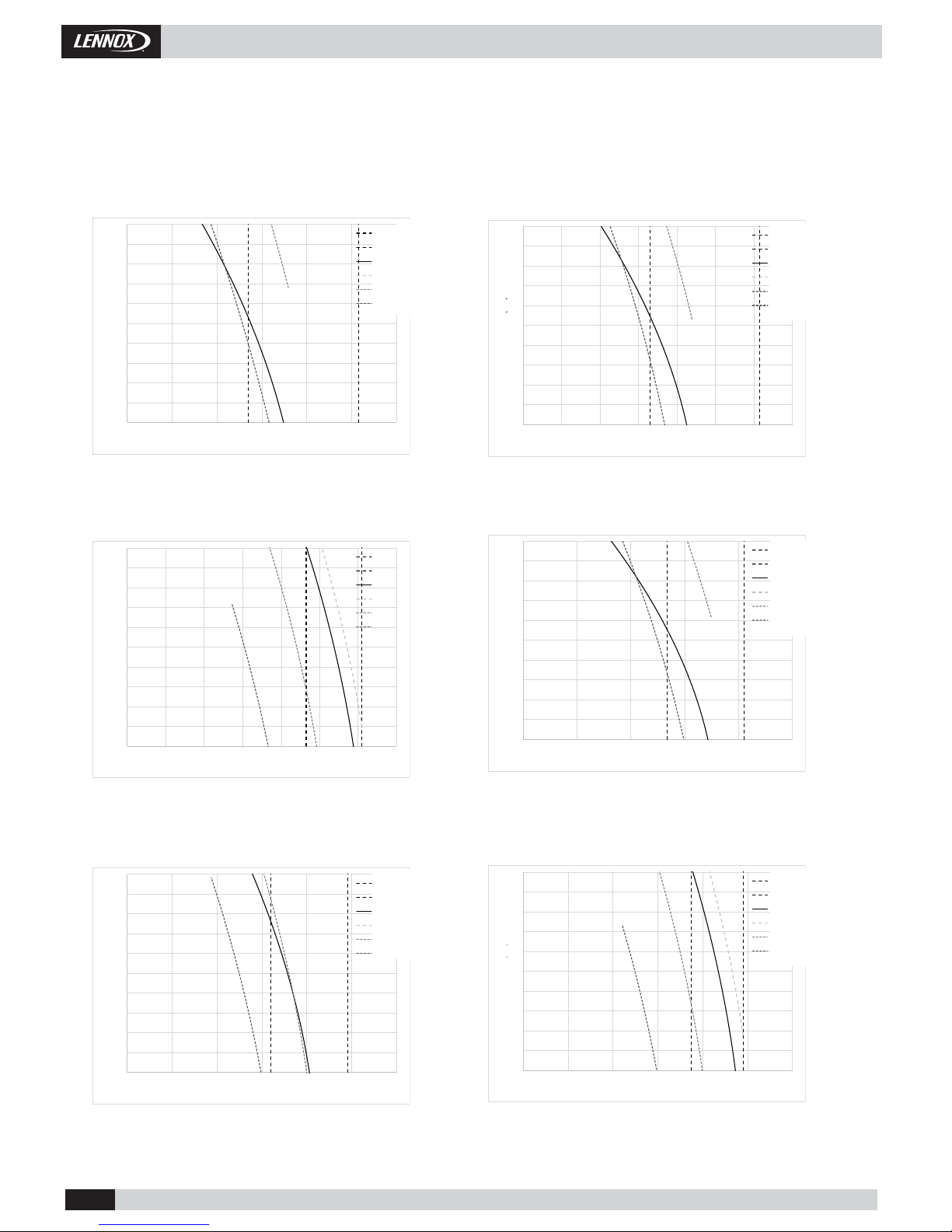
1.6.- FAN PERFORMANCES.
INDOOR FANS (Nominal speed).
Pressure (Pa)
Air Flow (m 3/h)
Air Flow (m 3/h)
Pressure (Pa)
Air Flow (m 3/h)
Air Flow (m 3/h)
Pressure (Pa)
Pressure (Pa)
Pressure (Pa)
Air Flow (m 3/h)
Air Flow (m 3/h)
Pressure (Pa)
Min Airfl ow
Max Airfl ow
Nominal
100 %
80%
60%
Min Airfl ow
Max Airfl ow
Nominal
100 %
80%
60%
Min Airfl ow
Max Airfl ow
Nominal
100 %
80%
60%
Min Airfl ow
Max Airfl ow
Nominal
100 %
80%
60%
Min Airfl ow
Max Airfl ow
Nominal
100 %
80%
60%
Min Airfl ow
Max Airfl ow
Nominal
100 %
80%
60%
Page 14
• 13 •
CAMH025SM1M
CASH025SM1M
CAMH035SM1M
CASH035SM1M
CAMH045SM1M
CASH045SM1M
CAMH060DM1M
CASH060DM1M
CAMH075DM1M
CASH075DM1M
CAMH085DM1M
CASH085DM1M
0
50
100
150
200
250
300
350
400
450
500
0 2000 4000 6000 8000 10000 12000
Pressure (Pa)
Air Flow (m3/h)
Min Air Flow
Max Air Flow
Nom Reg
Reg 100%
Reg 80%
Reg 60%
0
50
100
150
200
250
300
350
400
450
500
0 2000 4000 6000 8000 10000 12000 14000
Pressure (Pa)
Air Flow (m3/h)
Min Air Flow
Max Air Flow
Nom Reg
Reg 100%
Reg 80%
Reg 60%
0
50
100
150
200
250
300
350
400
450
500
0 2000 4000 6000 8000 10000 12000 14000
Pressure (Pa)
Air Flow (m3/h)
Min Air Flow
Max Air Flow
Nom Reg
Reg 100%
Reg 80%
Reg 60%
0
50
100
150
200
250
300
350
400
450
500
0 5000 10000 15000 20000 25000
Pressure (Pa)
Air Flow (m3/h)
Min Air Flow
Max Air Flow
Nom Reg
Reg 100%
Reg 80%
Reg 60%
0
50
100
150
200
250
300
350
400
450
500
0 5000 10000 15000 20000 25000 30000
Pressure (Pa)
Air Flow (m3/h)
Min Air Flow
Max Air Flow
Nom Reg
Reg 100%
Reg 80%
Reg 60%
0
50
100
150
200
250
300
350
400
450
500
0 5000 10000 15000 20000 25000 30000
Pressure (Pa)
Air Flow (m3/h)
Min Air Flow
Max Air Flow
Nom Reg
Reg 100%
Reg 80%
Reg 60%
Installation Manual • COMPACTAIR ADV IOM-MIL157E-0418
1.6.- FAN PERFORMANCES.
Pressure (Pa)
Air Flow (m 3/h) Air Flow (m 3/h)
Pressure (Pa)
OUTDOOR FANS.
1.- GENERAL CHARACTERISTICS
Pressure (Pa)
Air Flow (m 3/h)
Air Flow (m 3/h)
Pressure (Pa)
Air Flow (m 3/h)
Air Flow (m 3/h)
Pressure (Pa)
Pressure (Pa)
Min Airfl ow
Max Airfl ow
Nominal
100 %
80%
60%
Min Airfl ow
Max Airfl ow
Nominal
100 %
80%
60%
Min Airfl ow
Max Airfl ow
Nominal
100 %
80%
60%
Min Airfl ow
Max Airfl ow
Nominal
100 %
80%
60%
Min Airfl ow
Max Airfl ow
Nominal
100 %
80%
60%
Page 15

• 14 •
CH
B12B11
Acumulador
Aspiración
Compresor
Scroll BLDC
Válvula expansión
electrónica
Filtro secador
CH
B12
B11
Acumulador
Aspiración
Compresor
Scroll BLDC
Filtro secador
UNIDAD EXTERIORUNIDAD INTERIOR
Separador de aceite
Filtro secador
Válvula 4 vías
Válvula 4 vías
Válvula retención
Válvula retención
Válvula expansión
electrónica
Válvula expansión
electrónica
BS1
BS1
BS14
BS14
B13
B13
BS13
BS13
B13_1
BS13_1
BS4
BS4
BS2
BS2
Ventilador
PLUG FAN
Ventilador
PLUG FAN
Ventilador
PLUG FAN
Ventilador
PLUG FAN
CH
B11
B12
B13
B13_1
BS1
BS14
BS4
BS2
BS13
BS13_1
Installation Manual • COMPACTAIR ADV IOM-MIL157E-0418
1.- GENERAL CHARACTERISTICS
1.7.- HEAT PUMP PIPING DRAWINGS.
Pressure gauge. (5/16" to be fi tted by the installer).
High pressure switch.
High pressure transducer.
Low pressure transducer.
Crank case heater.
Outdoor temperature sensor.
Unloading sensor.
Suction sensor.
Air return sensor.
Impulsion air sensor.
CAMH025 & CAMH035 & CAMH045
PACKAGE UNITS
PIPING DRAWINGS
CASH/CAIH025 & CASH/CAIH035 & CASH/CAIH045
SPLIT UNITS
PIPING DRAWINGS
Page 16

• 15 •
CH
B11
B21
B12
B22
B13
B23
B13_1
B23_1
BS1
BS14
BS24
BS4
BS2
BS13
BS23
BS13_1
BS23_1
CH
B12B11
Acumulador
Aspiración
Compresor
Scroll BLDC
Válvula expansión
electrónica
Filtro secador
Válvula 4 vías
Válvula retención
BS1
BS14
B13
BS13
BS4
BS2
B22B21
Acumulador
Aspiración
Válvula expansión
electrónica
Filtro secador
Válvula 4 vías
Válvula retención
BS1
BS24
B23
BS23
BS2
BS4
Ventilador
PLUG FAN
Ventilador
PLUG FAN
Batería
Ventilador
PLUG FAN
Ventilador
PLUG FAN
CH
CH
Installation Manual • COMPACTAIR ADV IOM-MIL157E-0418
1.- GENERAL CHARACTERISTICS
1.7.- HEAT PUMP PIPING DRAWINGS.
Pressure gauge. (5/16" to be fi tted by the installer).
High pressure switch.
High pressure transducer.
Low pressure transducer.
Crank case heater.
Outdoor temperature sensor.
Unloading sensor.
Suction sensor.
Air return sensor.
Impulsion air sensor.
CAMH025 & CAMH035 & CAMH045
PACKAGE UNITS
PIPING DRAWINGS
Page 17

• 16 •
CH
B12
B11
Acumulador
Aspiración
Compresor
Scroll BLDC
Filtro secador
UNIDAD EXTERIORUNIDAD INTERIOR
Separador de aceite
Filtro secador
Válvula 4 vías
Válvula retención
Válvula expansión
electrónica
Válvula expansión
electrónica
BS1
BS14
B13
BS13
B13_1
BS13_1
B22
B21
Acumulador
Aspiración
Filtro secador
UNIDAD EXTERIORUNIDAD INTERIOR
Separador de aceite
Filtro secador
Válvula 4 vías
Válvula retención
Válvula expansión
electrónica
Válvula expansión
electrónica
BS1
BS24
B23
BS23
B23_1
BS12_1
Ventilador
PLUG FAN
Ventilador
PLUG FAN
BS4
BS2
BS2
Ventilador
PLUG FAN
Ventilador
PLUG FAN
Batería
BS4
CH
CH
CH
B11
B21
B12
B22
B13
B23
B13_1
B23_1
BS1
BS14
BS24
BS4
BS2
BS13
BS23
BS13_1
BS23_1
Installation Manual • COMPACTAIR ADV IOM-MIL157E-0418
CASH/CAIH025 & CASH/CAIH035 & CASH/CAIH045
SPLIT UNITS
PIPING DRAWINGS
1.- GENERAL CHARACTERISTICS
1.7.- HEAT PUMP PIPING DRAWINGS.
Pressure gauge. (5/16" to be fi tted by the installer).
High pressure switch.
High pressure transducer.
Low pressure transducer.
Crank case heater.
Outdoor temperature sensor.
Unloading sensor.
Suction sensor.
Air return sensor.
Impulsion air sensor.
Page 18

• 17 •
025
Hz 63 125 250 500 1000 2000 4000 8000
Lwa
dB(A)
49,9 54,5 63,7 66,3 63,9 61,2 61,9 60,4 70
60,3 66,2 74,1 76,8 76,4 77,0 74,8 74,7 83
50,4 59,1 64,2 67,5 70,2 72,5 68,8 69,6 77
49,9 54,5 63,7 66,3 63,9 61,2 61,9 60,4 70
60,3 65,2 74,1 76,7 75,0 73,4 72,8 71,6 81
50,3 56,3 64,1 66,9 66,9 66,7 64,3 63,8 73
035
Hz 63 125 250 500 1000 2000 4000 8000
Lwa
dB(A)
57,9 62,5 71,7 74,3 71,9 69,2 69,9 68,4 78
64,8 71,6 75,1 75,1 75,7 78,9 75,0 77,5 54
55,5 65,5 65,8 66,1 69,1 72,3 69,4 71,8 77
57,9 62,5 71,7 74,3 71,9 69,2 69,9 68,4 78
64,6 69,9 74,9 74,9 74,5 77,6 72,7 75,3 82
54,8 61,8 65,1 65,2 66,1 68,8 64,5 66,8 74
045
Hz 63 125 250 500 1000 2000 4000 8000
Lwa
dB(A)
63,8 68,4 74,1 74,0 73,1 76,4 71,2 74,0 81
71,6 76,7 81,9 81,8 81,3 85,4 80,8 82,1 90
61,8 68,4 72,2 72,1 72,8 78,1 74,3 73,2 82
63,8 68,4 74,1 74,0 73,1 76,4 71,2 74,0 81
71,5 76,3 81,8 81,8 80,9 84,4 79,3 81,7 89
61,5 66,8 71,9 71,8 71,5 75,3 70,5 71,9 80
060
Hz 63 125 250 500 1000 2000 4000 8000
Lwa
dB(A)
63,5 68,1 77,3 79,9 77,5 74,8 75,5 74,0 83
67,8 73,6 78,1 78,2 78,3 81,5 77,6 79,8 86
58,1 66,5 68,5 69,0 71,2 74,1 71,5 73,4 79
63,5 68,1 77,3 79,9 77,5 74,8 75,5 74,0 83
67,7 72,7 78,0 78,0 77,5 80,7 76,0 78,4 86
57,8 63,8 68,1 68,3 68,9 71,7 68,1 69,9 77
075
Hz 63 125 250 500 1000 2000 4000 8000
Lwa
dB(A)
65,2 69,8 75,5 75,5 74,5 77,9 72,7 75,4 83
71,3 76,5 81,6 81,6 81,1 84,5 80, 82,5 89
61,5 68,2 71,8 71,9 72,5 76,0 72,8 74,9 81
65,2 69,8 75,5 75,5 74,5 77,9 72,7 75,4 83
71,3 76,1 81,6 81,6 80,8 84,1 79,2 81,8 89
61,3 66,6 71,7 71,7 71,3 74,6 70,4 72,6 80
085
Hz 63 125 250 500 1000 2000 4000 8000
Lwa
dB(A)
67,1 71,7 77,4 77,4 76,4 79,8 74,6 77,3 85
74,6 79,5 84,9 84,9 84,2 87,9 83,3 85,1 93
64,7 70,5 75,1 75,0 75,0 79,8 76,0 76,1 84
67,1 71,71 77,4 77,4 76,4 79,8 74,6 77,3 85
74,6 79,3 84,9 84,8 84,0 87,4 82,3 84,9 92
64,6 69,5 74,9 74,9 74,3 77,9 73,3 75,2 83
Installation Manual • COMPACTAIR ADV IOM-MIL157E-0418
1.- GENERAL CHARACTERISTICS
1.8.- SOUND LEVELES.
Values for the nominal conditions
Standard
unit
Indoor side in duct
Outdoor side in duct
Outdoor side radiated
Low noise
option
Indoor side in duct
Outdoor side in duct
Outdoor side radiated
Standard
unit
Indoor side in duct
Outdoor side in duct
Outdoor side radiated
Low noise
option
Indoor side in duct
Outdoor side in duct
Outdoor side radiated
Standard
unit
Indoor side in duct
Outdoor side in duct
Outdoor side radiated
Low noise
option
Indoor side in duct
Outdoor side in duct
Outdoor side radiated
Standard
unit
Indoor side in duct
Outdoor side in duct
Outdoor side radiated
Low noise
option
Indoor side in duct
Outdoor side in duct
Outdoor side radiated
Standard
unit
Indoor side in duct
Outdoor side in duct
Outdoor side radiated
Low noise
option
Indoor side in duct
Outdoor side in duct
Outdoor side radiated
Standard
unit
Indoor side in duct
Outdoor side in duct
Outdoor side radiated
Low noise
option
Indoor side in duct
Outdoor side in duct
Outdoor side radiated
Page 19

• 18 •
CAIH 025-035-045
CASH 025-035-045
179966300
1445
3766434
25
19 697
735
40
11267088
25
40
836
88670112
955
202
77 75
1869918
138126543
836
385 462 23
966179
895
TUBO DE DRENAJE M 3/4 G
CABLE INTERCONEXIÓN
UNIDAD EXTERIOR
ALIMENTACIÓN ELÉCTRICA
TUBO DE DRENAJE M 3/4 G
600
1497
15
1410
34052
928
341092
1445
291093
26
172
100
623
1380
870
35
84
11066793
85
1721171102
734
62
581
41
23830
570
895
25
709
109262
340468
ALIMENTACIÓN ELÉCTRICA
CABLE INTERCONEXIÓN
UNIDAD INTERIOR
TUBO DE DRENAJE M 3/4 G
Installation Manual • COMPACTAIR ADV IOM-MIL157E-0418
1.- GENERAL CHARACTERISTICS
1.9.- SPLIT UNITS DIMENSIONS.
Page 20

• 19 •
CAIH 060-075- 085
CASH 060-075-085
1043
126
1043
301 301
485385
2813
670 88112
955
837
40
25
89
1265
106
1265
89
1869918
836
25
40
19 697
735
11267088
870
202
77
75
298
1047
123
1047
299
35 665 35
2814
TUBO DE DRENAJE M 3/4 G
CABLE INTERCONEXIÓN
UNIDAD EXTERIOR
ALIMENTACIÓN ELÉCTRICA
TUBO DE DRENAJE M 3/4 G
2865
669
222
1092
116
1092
292
340468
1409
13
42
30 238 25
895
570
102 172
172
100
85
62
584 734
1171 1171197
84
709 623
1380
870
92 670 109
2813
1092
58
1092 252319
2491093
56
1092319
34 929
52 340 26
13
42
ALIMENTACIÓN ELÉCTRICA
CABLE INTERCONEXIÓN
UNIDAD INTERIOR
TUBO DE DRENAJE M 3/4 G
TUBO DE DRENAJE M 3/4 G
Installation Manual • COMPACTAIR ADV IOM-MIL157E-0418
1.- GENERAL CHARACTERISTICS
1.9.- SPLIT UNITS DIMENSIONS.
Page 21

• 20 •
CAMH 025-035-045
138126543
1445
1869918
214537 664 34
179 966 300
7775
533
711
40
19 697
112 670 88
112 670 88
955
40
711
735
85
100
100 1171 170
1527
62
734614
600
1497
928
52
340
1410
65
34 1092
1380
570
30
2145
15
41
84
709 623
667 91108
895
866
172
236 52
966179
385 462 23
1092 31632
TUBO DE DRENAJE M 3/4 G
TUBO DE
DRENAJE
M 3/4 G
TUBO DE
DRENAJE
M 3/4 G
ALIMENTACIÓN ELÉCTRICA
ALIMENTACIÓN ELÉCTRICA
CAMH 060-075-085
All dimensions in millimet
e
669
2865
462 23385
301
1043
126
1043
301
89
1265
106
1265
89
18699
2145
62
734613
100172
85
1171
196
1171
100
170
2895
2814
40
735 1380
2145
88670112
955
42
13
570
30
236
52
711
670
955
112 88
710
40
84
19 697
623709
107 670
866
90
13
42
77
75
533
1095
249
53 319
35
66535
1410
252
1092
58
319
249
1093
63929
52
340
35
1092
1047
123 298
1047
ALIMENTACIÓN ELÉCTRICA
TUBO DE DRENAJE M 3/4 G
TUBO DE DRENAJE M 3/4 G
TUBO DE
DRENAJE
M 3/4 G
TUBO DE
DRENAJE
M 3/4 G
ALIMENTACIÓN ELÉCTRICA
Installation Manual • COMPACTAIR ADV IOM-MIL157E-0418
1.- GENERAL CHARACTERISTICS
1.10.- PACKAGE UNITS DIMENSIONS.
Page 22

• 21 •
AB CDELMN
1 CIRCUITO
2 CIRCUITOS
1000 148,5 291 38,5 138 789,5 100 307
24
E
D
C
B
A
M
L
N
Installation Manual • COMPACTAIR ADV IOM-MIL157E-0418
STANDARD EXECUTION
OPTIONAL EXECUTION
(TO BE CARRIED OUT BY THE INSTALLER)
1.11.- AIR SUPPLY CONFIGURATIONS
1.- GENERAL CHARACTERISTICS
1.11.- OPTIONS.
INDOOR UNIT
1 CIRCUIT
025-035-045
INDOOR UNIT
2 CIRCUITS
060-075-085
Free-cooling
1.- OPERATION.
The control compares the values of temperature between outside air and room air by means of the probes; if there
is a negative difference and the safety elements allow (discharge temperature probes) then the control acts on the
servomotor, which opens the outside damper and closes the return damper, allowing cool outside air to enter the
room.
The damper is proportionally regulated. If there is not a great demand for air indoors, it may be enough just to have
free cooling to condition the room. If there is a greater demand for air, the free cooling and the unit may need to be
working in different cooling mode stages.
2.- SUPPLY AND INSTALLATION.
The free cooling option will be supplied loose.
The return probe must be installed in the return air intake duct.
FRESH AIR OPTIONS
Page 23

• 22 •
330
667
1267
330
667
1267
1267
734
700
1250
Installation Manual • COMPACTAIR ADV IOM-MIL157E-0418
High Effi ciency Filter: M5+F7.
The fi lter is supplied loose and must be placed in the fan exit.
FILTRATION OPTIONS.
INDOOR UNIT
1 CIRCUIT
025-035-045
INDOOR UNIT
2 CIRCUITS
060-075-085
1.11.- OPTIONS.
Return fan
Fan return cabinet is supplied loose
FRESH AIR OPTIONS
HIGH EFFICIENCY
FILTER: M5+F7
INDOOR UNIT
1 CIRCUIT
025-035-045
HIGH EFFICIENCY
FILTER: M5+F7
1.- GENERAL CHARACTERISTICS
Page 24

• 23 •
DC
DM
Service
Display
DS
025 035 045 060 075 085
ELHS2 (Kw) 10 10 10 15 15 15
ELHM2 (Kw) 15 15 15 20 20 20
ELHH2 (kW) 20 20 20 40 40 40
Installation Manual • COMPACTAIR ADV IOM-MIL157E-0418
DC - User terminal.
Remote controller very easy to use, with the following features:
o Switched on/Switvhed off.
o Operation selection mode: (Cold/Heat/Auto).
o Airfl ow manual adjustment (3 speeds).
o Environment temperature selection.
o Airfl ow settings (Mini/Nominal/Max/Auto).
o Time setting.
o Environment temperature display.
o Alarm codes display.
o Conected units supervision (until 10).
A control DS is requered to activate this function (Expert mode) and it must be
adjust by a Lennox technician.
DS - Service terminal.
Terminal which allows the access to the control menu and adjustment all parameters.
24V customer display situated to a maximum distance of 30 meters to the unit. Remote
reading and modifi cation of the customer parameters.
DM - Terminal to view time and zone settings.
It is possible to confi gure until 7 time zones each day with 4 operating modes per zone.
It can be confi gured with the DM or during installation by a Lennox technician.
1.- GENERAL CHARACTERISTICS
A differential pressure controller measures the charge loss through the evaporator coil and the fi lters. The set point
between dirty and clean can be checked by the installer.
DIRTY FILTER ANALOGICAL INDICATION.
Electric resistance.
It is supplied mounted on the unit.
The electrical heater must be supplied from the unit’s electrical box..
AUXILIARY HEATING OPTIONS.
Communications: MODBUS / BACNET / LONWORKS.
The control board is equipped with a RS485 serial communications port which allows remote management through a
communications bus. Depending on the desired communication protocol, the board can be equipped with the ModBUS®,
LonWorks® or BacNET® communications interface.
CONTROL OPTIONS.
Expansion Band.
In the package units, the expansion board is located in its electrical board and in the split units, the expansion board is
situated in the electrical board of the outdoor unit.
Units
1.12.- OPTIONS.
Page 25

• 24 • Installation Manual • COMPACTAIR ADV IOM-MIL157E-0418
Compressor acoustic insulation.
Attenuates the sound level produced by the unit through an insulation that covers the compressor.
Insulation air treatment unit.
This insulation, which covers the indoor unit, provides a fi re propagation rating A1.
OTHER OPTIONS.
1.12- OPTIONS.
1.- GENERAL CHARACTERISTICS
REFRIGERANT CIRCUIT.
Service valves.
Refrigerant precharged.
COILS TREATMENT.
Anticorrosion protection condensor & evaporator coils.
Indoor air quality sensor.
The indoor air quality is controlled with the CLIMATIC ™ main controller through a COV (volatile organic compound)
sensor which detects the amount of CO2 in the air between 0 and 2000 ppm. (This value varies depending on the occupancy levels of the space). The sensor sends a signal (0-20 mA) to the controller to modulate the outside air.
Environment remote sensor.
It can be used when you want to regulate through the temperature where the sensor is situated and not through the
return temperature, which is how the standard unit comes out.
Freecooling.
It is a energy saving system through a regulation of dampers, through which outside air is introduced to the local when
the outside temperature is lower than the local. This option is composed of regulating gate or gates and a servomotor.
Available in two versions with an external air damper, or adding a second damper for the return of the local.
Smoke detector.
Three phases relay for unit electrical protection.
ELECTRIC AND SECURING OPTIONS.
Page 26

• 25 • Installation Manual • COMPACTAIR ADV IOM-MIL157E-0418
2.- INSTALLATION
2.1.- PRELIMINARY PREPARATIONS.
All INSTALLATION, SERVICE and MAINTENANCE work must be carried
out by QUALIFIED PERSONNEL.
When unpacking the machine, have a correct segregation of non-hazardous waste coming from packaging: Plastic fi lm or other plas-
tic elements, metal strips, wood and pallets, through authorized dealers, or segregate
them in the containers destined for this purpose
Follow the installation instructions established in this manual to avoid disturbing noise caused by movement or shocks due to defi -
cient installation of the unit.
The unit must be transported in a VERTICAL POSITION on its metal mounting frame. Any other position may
cause serious damage to the machine.
When the unit is received, it should be checked to assure that it has received
no shocks or other damage, following the instructions on the packaging. If there is damage, the unit may be rejected by notifying
the LENNOX Distribution Department and stating why the machine is unacceptable on the transport agent’s delivery note. Any later
complaint or claim made to the LENNOX Distribution Department for this type of damage cannot be considered under the Guarantee.
The modifi cations that the customer makes in the units will be under his responsibility and in this case, the declaration of conformity
certifi cate of Lennox manufacturer will not be valid.
Suffi cient space must be allowed to facilitate installation of the unit.
When positioning the unit, be sure that the Rating Plate is always visible since this data will
be necessary to ensure correct maintenance.
The units are designed to be installed with ducts designed by qualifi ed technical staff.
The joints to be used between ducts and openings in the unit should be Elastic Joints.
Avoid the use of BYPASS joints between the extraction air and input air.
The structure where the unit is placed must be able to support the weight of the unit during operation.
2.2.- UNIT ACCEPTANCE.
Defrosting: To avoid ice accumulation in the driptray , it may be necessary to install an electrical
heater and inside the drainage connection , to drain correctly the water. The drainage must be always
accessible through the indoor part , in order to remove easily the dirty than may be accumulated.
Outdoor and packaged units are placed on wood pallet for transportation.
The indoor units have with metal legs which must be removed when positioning the unit
How to hoist the unit
Use forklift for unloading and placement the unit. The unit is not suitable for lifting with crane.
Page 27

• 26 • Installation Manual • COMPACTAIR ADV IOM-MIL157E-0418
2.- INSTALLATION
2.3.- UNIT LOCATION.
- The bedplate is made up of two metal channels, capable of with standing the weight of the units whether hung from the ceiling or
mounted on the fl oor.
- If the unit is fl oor mounted, then the profi les should be isolated with shock absorbing material such as anti-vibration or pads. Place
the anti-vibration to avoid any buckling.
- The unit is able to work in normal radioelectronic conditions for commercial and residential installations. For any other conditions
please consult.
- If the outside temperature in the area where the heat pump unit is to be installed is low or the cycle functioning are too long, it may
necessary to install an electrical heater, below the likely coils on the drip tray, which avoids the causing of ice in the coil during defrost
cycle.
INDOOR SECTION OUTDOOR SECTION
DUCTS
Supply Install 1 or 2 ducts Mandatory 2 ducts*
Return Install 1 duct Install 1 duct
SENSORS POSITION
Supply Placed in the fan cabinet in the indoor secƟ on.
Return Install in the retun duct
Outdoor Place in the installaƟ on to assure outdoor temperature measurement.
* To avoid by-pass
Place sheet metal duct connections in the indoor air supply and fi ix sensors.
2.4.- DUCTS AND SENSOR INSTALLATION
Page 28

• 27 •
2%
2%
1 m.
1 m.
1 m.
1 m.
Installation Manual • COMPACTAIR ADV IOM-MIL157E-0418
2.- INSTALLATION
2.5.- INSTALLATION CLEARANCES.
Clearance around the unit for service and maintenance.
SERVICE SPACE
Space should be left free for access or servicing, to ease the installation of ducts, drainage connections, electric installation and
cleaning fi lters, as well as easy access to the unit.
2.6.- DRAINS.
All the outdoor and indoor sections of these units have a 3/4” steel threaded drain pipe welded to the condensation tray.
The units which have a double circuit (060/075/085) have two drain pipes, one on each side and both have to be connected.
Drainage pipes will be fi tted for each tray through a siphon with a height difference
of 80 mm. to avoid drainage problems from the depression formed by the fans.
The pipes should have an inclination of 2% to ease drainage of condensation.
Also slightly tip the unit toward the drainage side. Check that the
condensation trays are clean and free from dirt and other debris from the works
and that water drains correctly.
The drains must be independents, no connect the condenser drain with the
evaporator drain
Mín. 80 mm.
Inspection and cleaning stopper
LOCATION
Install air entry and exit ducts should be fi tted. The unit should be assembled on bases previously made and stood on absorbent and
antivibrating material to avoid the vibrations being transmitted to the structure of the building.
Place the anti-vibration to avoid any buckling.
To assure proper water evacuation in the base of the unit to avoid overfl ow or ice accumulation
Page 29

• 28 • Installation Manual • COMPACTAIR ADV IOM-MIL157E-0418
2.- INSTALLATION
2.7.- REFRIGERANT CONNECTIONS
Split units are supplied with gas and liquid lines sealed with copper covers, and located 60mm from casing.
Split units are supplied with nitrogen gas, which must be removed before carrying other operation and then
proceed as follow.
Cupper cover
Brazing
Gas
Liquid
1. Remove the nitrogen gas through the high and low 5/16” service ports located inside and provide a low vacuum for safety.
2. Remove the caps from the connecting lines.
3. Braze the piping connection lines. Select piping diameter from table 2.6.1.
(When brazing refrigerant pipes, nitrogen gas must be supplied into the pipes through the service ports to remove the air).
4. Leak test:
Add nitrogen gas, check that a pressure of 5 kg/cm
2
has been reached and that there are no leaks in the circuit or brazing
by applying soapy water to the pipes which will cause the bubbles to form where there are leaks.
To detect small leaks, proceed as follows:
Add nitrogen gas and check that a pressure of 25 kg/cm2 has been reached, there are no leaks if the pressure remains the same
for at least 24 hours and the fi nal pressure is not less than 10% below the initial pressure.
5. Ensure that the gas line is insulated.
6. Evacuation:
Remove the nitrogen gas, connect the gauge manifold and vacuum pump to both the liquid and gas lines, fully open the gauge
manifold valve and switch on the vacuum pump. Check to make sure the gauge shows a pressure of -750mm Hg. Once a level
of -750mm Hg is reached, keep the vacuum pump running for at least one hour.
7. Refrigerant charge:
- Check TABLE for the amount of refrigerant charge, depending on the length and size of the pipe connections.
- Disconnect the vacuum pump and connect to the refrigerant-charging bottle. Open the charging pump and purge the air from
the hose at the pressure gauge manifold.
- Set up the amount of additional refrigerant on the weighing scale, open the high pressure and charged in the liquid state. If the
total amount of refrigerant charge has not been reached because the pressure is balanced, turn off the high side of the gauge
manifold, turn on the unit, and add the remaining amount of the refrigerant charge required slowly through the low side of the
pressure gauge. (With R-410A refrigerant, the charging bottle must be in a vertical position and charged in the liquid state).
Close the pressure gauge, disconnect it from the from the service port of the unit and fi t caps on the service ports. The unit is
then ready to operate.
During installation operations, keep gas and liquid pipes covered, in order to prevent humidity and dirt,
get into them.
Take special concern about refrigerant pipes are isolated.
Avoid collapse on line installation.
Legislation does not allow refrigerant gas emissions to the atmosphere, so the refrigerants have to be
recycled to avoid being released to the atmosphere. Those recycled refrigerants shall be processed afterwards by an authorized waste manager.
Those components derived from the recycling of the unit have to be managed by authorized waste manager or be left in local waste facilities according the local normative in each country.
Page 30

• 29 •
2%
2
1
B
L
2%
2%
2
1
C
L
2%
2%
A
L
2
1
Installation Manual • COMPACTAIR ADV IOM-MIL157E-0418
2.7- REFRIGERANT CONNECTIONS
To locate the outdoor and the indoor units, refer to the following information:
POSITION C : Install a siphon at the base of the vertical of the gas line; no
more siphons are necessary. Maximum vertical length 16m.
NOTE: The refrigerant connections are brazing
connections. Service valves can be supplied as
option if required.
- THE GAS LINE MUST BE ALWAYS INSULATED.
- THE HORIZONTAL LINES MUST BE TIPPED AT LEAST 2% TOWARD THE OUTDOOR UNIT.
- THE MAXIMUM SPEED INSIDE LINES SHOULD NOT BE MORE THAN 15 m/seg.
OUTDOOR UNIT
INDOOR UNIT
A,B,C : Unit positions
L : Total length
1 = Gas line
2 = Liquid line
OUTDOOR UNIT
INDOOR UNIT
OUTDOOR
UNIT
INDOOR UNIT
POSITION A : A syphon suction must be installed at the base of the vertical of the
gas line, and syphons must be installed every 8 meters upward. The minimum speed
suction must not be below 6m/s. Maximum vertical length 16m.
POSITION B : Tip the lines toward the outdoor unit. Make special attention
to line length longer than 10m and avoid collapse on pipe lines installation.
2.- INSTALLATION
Page 31

• 30 •
1/2
”7/8”108
5/8”
1-1
/8”
17
7
5/8”1-3/8”182
3/4”1-3/8”265
3/4”1-5/8”
27
1
7
/8”1-5/8”
3
74
025S 035S 045S 060D 075D 085D 025S 035S 045S 060D 075D 085D
C1
1/2” 5/8” 5/8” 5/8” 5/8” 5/8” 1/2” 5/8” 5/8” 5/8” 5/8” 5/8”
C2
n/a n/a n/a 5/8” 5/8” 5/8” n/a n/a n/a 5/8” 5/8” 5/8”
C1
7/8” 1 1/8” 1 3/8” 1 1/8” 1 1/8” 1 3/8” 5/8” 7/8” 1 1/8” 7/8” 7/8” 1 1/8”
C2
n/a n/a n/a 1 1/8” 1 3/8” 1 3/8” n/a n/a n/a 7/8” 7/8” 1 1/8”
12 12 12 12 12 12 12 12 12 12 12 12
C1
5/8” 5/8” 3/4” 5/8” 5/8” 3/4” 5/8” 5/8” 3/4” 5/8” 5/8” 3/4”
C2
n/a n/a n/a 5/8” 5/8” 3/4” n/a n/a n/a 5/8” 5/8” 3/4”
C1
1 1/8” 1 3/8” 1 5/8” 1 3/8” 1 3/8” 1 5/8” 5/8” 7/8” 1 1/8” 7/8” 7/8” 1 1/8”
C2
n/a n/a n/a 1 3/8” 1 5/8” 1 5/8” n/a n/a n/a 7/8” 7/8” 1 1/8”
12 12 18 18 18 18 12 12 18 18 18 18
Installation Manual • COMPACTAIR ADV IOM-MIL157E-0418
TABLE 1: REFRIGERANT LINES SELECTION
n/a: not available
The unit is supplied with brazing connections. As an option , the unit can be supplied with gas precharge from the factory ; in that case only the TABLE 2 has to be taken into account. ( this option includes the service valves).
TABLE 2 : EXTRA REFRIGERANT CHARGE R410A BY METER OF COPPER PIPE
Liq
uid
G
as
gr/m
The unit is precharged from factory with nytrogene . The installer should remove this gas and charge the units
with the charge of refrigerant R410A , shown in the following tables plus the charge by additional meter shown in
the TABLE 2
In the double circuit units , check before connecting C1 and C2 circuits , that they are the same circuit for the indoor
and the outdoor section
REFRIGERANT LINES
UNIT - MODEL
UNIT -MODEL Position A
Vertical line
Total line length
(refrigerant line
length between
indoor and
ourtoor units)
0 to 30 m.
(Standard
conection
unit)
Ø Lquid
Ø Gas
Max. n
er
of bends
30 to 45 m.
Ø Liquid
Ø Gas
Max. n
er
of bends
2.7- REFRIGERANT CONNECTIONS
2.- INSTALLATION
Legislation does not allow refrigerant gas emissions to the atmosphere, so the refrigerants have to be
recycled to avoid being released to the atmosphere. Those recycled refrigerants shall be processed afterwards by an authorized waste manager.
Those components derived from the recycling of the unit have to be managed by authorized waste manager
or be left in local waste facilities according the local normative in each country.
Page 32

• 31 •
CFM
BS1
BS0
BH10
BS2
B51
MS
MC
Installation Manual • COMPACTAIR ADV IOM-MIL157E-0418
2.- INSTALLATION
2.8.- ELECTRICAL CONNECTIONS.
- Before making the electrical connections, ensure that all circuit breakers are open.
- To make the elctrical connections, follow the electrical diagram supplied with the unit.
- Take into account the current standard for the installation of the unit, whether local, regional or national standards.
- USE SUPERINMUNIZED DIFFERENTIAL SWITCHES.
2.8.1.- ELECTRICAL CONNECTION FOR PACKAGE UNITS.
Connection 1
Unit Base unit Base unit + ELHS Base unit + ELHM Base unit + ELHHM
025 4G x 6mm² 4G x 10mm²
035 4G x 6mm² 4G x 16mm²
045 4G x 10mm² 4G x 16mm²
060 4G x 16mm²
3 x 50mm²
1 x 25mm²
075
3 x 25mm²
1 x 16mm²
3 x 50mm²
1 x 25mm²
085
3 x 25mm²
1 x 16mm²
3 x 70mm²
1 x 55mm²
Page 33

• 32 •
CFM
BS1
FASHFAIH
BS0
BH10
FM
BS2
MCMS
Installation Manual • COMPACTAIR ADV IOM-MIL157E-0418
2.8.2.- ELECTRICAL CONNECTION FOR SPLIT UNITS.
2.- INSTALLATION
- Before making the electrical connections, ensure that all circuit breakers are open.
- To make the elctrical connections, follow the electrical diagram supplied with the unit.
- Take into account the current standard for the installation of the unit, whether local, regional or national standards.
- USE SUPERINMUNIZED DIFFERENTIAL SWITCHES.
2.8.- ELECTRICAL CONNECTIONS.
Connection 1 Connection 31
Connection 32
Unit Base unit Base unit ELHS ELHM ELHHM Interconnection
025 4G x 4mm² 4G x 2.5mm² 4G x 6mm² 3 x 0.5mm² shielded
035 4G x 6mm² 4G x 2.5mm² 4G x 6mm² 3 x 0.5mm² shielded
045 4G x 6mm² 4G x 2.5mm² 4G x 6mm² 3 x 0.5mm² shielded
060 4G x 10mm² 4G x 2.5mm² 4G x 16mm² 3 x 0.5mm² shielded
075 4G x 16mm² 4G x 2.5mm² 4G x 16mm² 3 x 0.5mm² shielded
085 4G x 16mm² 4G x 2.5mm² 4G x 16mm² 3 x 0.5mm² shielded
Page 34

• 33 • Installation Manual • COMPACTAIR ADV IOM-MIL157E-0418
2.- INSTALLATION
2.9.1.- TERMINAL CONNECTION WITH PACKAGE UNIT.
IMPORTANT !
THE SHIELDED CONNECTING CABLE BETWEEN THE CONTROL PANEL AND THE UNIT MUST
BE SEPARATED FROM ANY OTHER TYPE OF ELECTRICAL WIRING. CONNECT IT TO THE
ELECTRIC PANEL LOCATED IN THE OUTDOOR UNIT.
NOTES:
- For securing and connecting the Control Panel, consult the control panel Manual supplied with the unit.
- Connection between the DC and the unit must be made using shielded twisted pair cables and shielded
(where the
screens is connected to ground by the side of the electrical panel) and with a hose of two cables.
- The Tx+ and Tx- polarity must strictly comply with the electrical diagram supplied with the unit.
- Wiring the hose separated from the power cables a minimum of 500mm.
- Wiring the hose separated from the halogen lamps a minimum of 500mm.
- Wiring the hose separated from switchboard, antennas, transmitters... a minimum of 500mm.
- NEVER ROLL UP THE EXCESSING HOSE, CUT THE HOSE FROM THE SIDE OF THE TERMINAL.
2.9.- TERMINAL CONNECTION.
Page 35

• 34 • Installation Manual • COMPACTAIR ADV IOM-MIL157E-0418
2.9.2.- TERMINAL CONNECTION WITH SPLIT UNIT.
2.- INSTALLATION
2.9.- TERMINAL CONNECTION.
IMPORTANT !
THE SHIELDED CONNECTING CABLE BETWEEN THE CONTROL PANEL AND THE UNIT MUST BE SEPARATED FROM ANY OTHER TYPE OF ELECTRICAL WIRING. CONNECT IT TO THE ELECTRIC PANEL LOCATED
IN THE OUTDOOR UNIT.
NOTES:
- For securing and connecting the Control Panel, consult the control panel Manual supplied with the unit.
- Connection between the DC and the unit must be made using shielded twisted pair cables and shielded (where the
screens is connected to ground by the side of the electrical panel) and with a hose of two cables.
- The Tx+ and Tx- polarity must strictly comply with the electrical diagram supplied with the unit.
- Wiring the hose separated from the power cables a minimum of 500mm.
- Wiring the hose separated from the halogen lamps a minimum of 500mm.
- Wiring the hose separated from switchboard, antennas, transmitters... a minimum of 500mm.
- NEVER ROLL UP THE EXCESSING HOSE, CUT THE HOSE FROM THE SIDE OF THE TERMINAL.
Page 36

• 35 • Installation Manual • COMPACTAIR ADV IOM-MIL157E-0418
3.- COMMISSIONING AND OPERATION
3.1.- PRELIMINARY CHECKS BEFORE START UP.
Legislation does not allow refrigerant gas emissions to the atmosphere, so the refrigerants have to be recycled
to avoid being released to the atmosphere. Those recycled refrigerants shall be processed afterwards by an
authorized waste manager.
Those components derived from the recycling of the unit have to be managed by authorized waste manager or be
left in local waste facilities according the local normative in each country.
1. Check that drain pipe connections, their fi xtures and that the level of the unit is tipped toward the drain.
2. Inspect the state of the ducts and grilles (clean and open grilles, no breaks in the duct, etc.).
3. Check that the power supply is the same as stated on the Rating Plate which is in agreement with the electrical diagram for the unit and that cable sizes are correct. Check that tightness of the electrical connections to their terminals
and to ground.
4. Inspect the air fi lter, which should be in its housing and properly positioned (the metal grille should be toward the
inside).
FIGURE FOR THE STANDARD UNIT CONFIGURATION FOR PACKAGE MODELS
060D-075D-085D
Page 37

• 36 • Installation Manual • COMPACTAIR ADV IOM-MIL157E-0418
3.- COMMISSIONING AND OPERATION
3.2.- PRELIMINARY CHECKS DURING START UP.
LENNOX REFAC, S.A. Designs and develops its machines always looking for the greater comfort and well-being of its customers
and users, at the same time as the greater energy effi ciency of the elements that constitute the units. This effort would be fruitless
if it was not united to a responsible use of these equipment. For this reason, we invite you to use these machines in a responsible
way with the environment, combining the adequate comfort, with a responsible consumption of the energy resources. To start the
unit, follow the instructions given in the User Manual for the control supplied with the unit
(requiring operation in any of the modes, cooling, heating, or automatic).
After a time delay, the unit will start.
With the unit operating, check that the fans are turning freely and in the correct direction.
CHECK THAT THE COMPRESSOR IS ROTATING IN THE CORRECT DIRECTION:
- If you have the option phase rotation indicator, use it to check the correct rotation.
- If you do not have three phase return lock, check the correct direction of rotation. The suction pressure decreases and the discharge
pressure increases when the compressor is started.
- If the connection is incorrect, rotation will be reversed, causing a high noise level and a reduction in the amount of current consumed.
If this occurs, the compressor’s internal protection system will operate to shut down the unit. The solution is to disconnect, reverse
two of the phases and connect again.
ASTP Protection is included with the fi x speed compressors . See "Fault diagnosis" for more information.
WITH OPERATING UNIT, CHECK:
- Low pressure and high pressure.
- Use the evaporating and liquid temperature to calculate superheat and subcooling.
- Adjust the refrigerant charge and/or expansion valve according to the preceding values.
Page 38

• 37 • Installation Manual • COMPACTAIR ADV IOM-MIL157E-0418
3.- COMMISSIONING AND OPERATION
The unit must be installed in accordance with local safety
codes and regulations and can only be used in a well ventilated area. Please read carefully the manufacturer’s instructions before starting this unit.
All work on the unit must be carried out by a qualifi ed
and authorised employee.
Non-compliance with the following instructions may result
in injury or serious accidents.
Work on the unit:
The unit shall be isolated from the electrical supply by disconnection and locking using the main isolating switch.
Workers shall wear the appropriate personal protective
equipment (helmet, gloves, glasses,etc.).
Electrical system:
Work on electric components shall be performed with the
power off (see below) by employees having valid electrical qualifi cation and authorisation.
Electrical connections can become loose during transport.
Please check them before starting-up the unit Compressors with specifi c rotation direction. Check the correct
rotation direction of the fan before closing the compressor
circuit breakers. If the direction is incorrect, the phases
must be reversed at the head of the main switch.
Refrigerating circuit(s):
After more than 12 hours of power cut, the cranckcase
heater (compressor) should be powered for 5 hours before any return to service. Non-compliance with this instruction can cause deterioration of the compressors.
Monitoring of the pressures, draining and fi lling of the sys-
tem under pressure shall be carried out using connections
provided for this purpose and suitable equipment. To prevent the risk of explosion due to spraying of coolant and
oil, the relevant circuit shall be drained and at zero pressure before any disassem bly or unbrazing of the refrigerating parts takes place.
To evoid the risks of explosion, cooling gases elements
and oil, shall check, before carrying out any dismant-
ling or dissamble any cooling elements, that the circuit
that cause the explosion and its pressure is zero.
There is a residual risk of pressure build-up by degassing the oil or by heating the exchangers after the circuit
has been drained. Zero pressure shall be maintained
by venting the drain connection to the atmosphere on
the low pressure side.
The brazing shall be carried out by a qualifi ed brazier
and shall comply according to code ASME section IX
following the procedures specifi cation.
Before the start up:
- Raise the system to the test maximum pressure (see
fi rmplate).
- Check the correct behaviour of the high pressure device.
- Check the components general condition and circuit
piping.
Spare parts:
In order to maintain CE marking compliance, replacement of components shall be carried out using spare
parts, or using parts approved by Lennox.
Only the coolant shown on the manufacturer’s nameplate shall be used, to the exclusion of all other products
(mix of coolants, hydrocarbons, etc.).
CAUTION:
In case of fi re, cooling circuits can
cause an explosion and spray
coolant gas and oil.
3.2.- PRELIMINARY CHECKS DURING START UP.
Page 39

• 38 • Installation Manual • COMPACTAIR ADV IOM-MIL157E-0418
3.- COMMISSIONING AND OPERATION
3.3.- CLIMA TIC™ CONFIGURATION
Settings
1. Supply Air-fl ow adjustement (depending on customer requirements)
a. 3333 = nominal air fl ow / pressure
b. 3334 = reduced air fl ow / pressure
2. Scheduling (depending on customer requirements)
a. Zones & Modes (Night/Day/Day I/ DayII)
b. Setpoints per mode
3. Regulation temperature probe selection
a. Select the regulation probe (DC, Return, Customer, etc.) in the Room Temp. Confi g screen
4. Outside temperature probe selection
a. Select the outdoor temp probe (Unit, Customer) in the Outside Temp. Confi g screen
5. Air quality sensor selection (optional)
a. Select the air quality CO2 sensor (Remote, Customer) in the CO2 Confi g screen
6. Remote display confi guration
a. 3151 = DC simple / DC full / DM
7.Minimum fresh air
a. 3121 = minimum opening %
Page 40

• 39 • Installation Manual • COMPACTAIR ADV IOM-MIL157E-0418
Commissioning
Check:
1. Airfl ow Vs Damper
a. Test B.Nom100% :
i. adjust the blower speed % (3333)to get the required air-fl ow
ii. adjust the exhaust speed % (3864) to get the required air-fl ow
b. Test B.Nom0%:
i. adjust the damper compensation (3335) to maintain the required air-fl ow even with damper fully
closed.
ii. adjust the damper compensation (3336) to maintain the required air-fl ow even with damper fully
closed.
2. Filter safety thresholds
a. Test B.Nom100% and Test B.Nom0%: read fi lter ΔP (3442) and adjust the bigger measure multiplied by 2.5
at threshold 3345
3. Frigorifi c circuit tests
a. Cooling mode
i. Test C---Cool: (if variable speed compressor, set speed value)
1. Check circuit pressures and temperatures
2. Check electrical consumptions
b. Heating mode
i. Test C---Heat: (if variable speed compressor, set speed value)
1. Check circuit pressures and temperatures
2. Check electrical consumptions
4. Unit option tests
a. Electrical Auxiliary heaters (Test H1-1 full)
i. Check supply temperature
ii. Check electrical consumption
5. Advanced regulation optimization
a. Auxiliary heaters ΔT (Gas burner or electrical)
i. Heating.
1. Test H1-1: read │Mix-Supply| temp and adjust heaters stage ΔT at menu 3734
b. Staging sequence(compressor/electrical)
i. Aux Heaters Priority 3731= Never/ Always /OutTemp
c. Dynamic setpoint
i. 3225= ΔT between customer set point and outdoor temperature
d. Fine temperature control
i. Smooth 3231= No/ DeadZone/Comfort
Once all the settings have been adjusted, the list of parameters must be downloaded (Wizard tool), stored and signed
by the customer.
3.- COMMISSIONING AND OPERATION
WARNING! During the settings, wait until the
economizer is fully closed or opened, since it
takes 1-2 minutes to switch.
Page 41

• 40 • Installation Manual • COMPACTAIR ADV IOM-MIL157E-0418
4.- MAINTENANCE
SIDE
REMOVAL
PREVENTIVE MAINTENANCE PREVENTS COSTLY REPAIRS,
THIS REQUIRES PERIODIC INSPECTIONS:
- GENERAL STATE OF THE CASING:
Casing, paint, damage due to shocks, rust spots, levelling and supporting, condition of the shock absorbers, if installed,
screwed panels, etc.
- ELECTRICAL CONNECTIONS:
State of hoses, tightness of screws, earthing, current consumption of the compressor and fans and check that the unit is
receiving the correct voltage.
- COOLING CIRCUIT:
Check that the pressures are correct and that there are no leaks. Check that there is no damage to the pipe insulation,
that the condition of the coils is good and that they are not blocked by bits of paper or plastic drawn in by the air fl ow, etc.
- COMPRESSOR:
If a sight glass is fi tted, check the oil level.
Check the condition of the silentblock mountings.
- FANS:
Check that fans turn freely and in the correct direction without excessive noise.
- CONTROL:
Check set points and normal operation.
- ELECTRIC PANEL GRILLES:
They must be kept clean for the entrance of the air circulation.
- AIR FILTER:
The air fi lter can be removed through the side by sliding it over the rail or downwards. (See fi gure).
For downwards removal, remove the two profi les that support it (depending on the model) which are under the fi lter
guide rail and screwed onto the unit.
The fi lter should be cleaned with a vacuum cleaner or washed in soapy water.
The frequency for cleaning or changing the air fi lters will depend on the quality air in the area (fumes, vapors,
suspended dust particles, etc.).
Remember that the metal grille should always be toward the inside of the unit.
- DRAINS:
Clean the base or drip tray, remove dirt in siphons and check if they are blocked by ice.
4.1.- PREVENTIVE MAINTENANCE.
LATERAL
EXTRACTION
When carrying out maintenance works on these units, please make a correct segregation of the non-hazardous waste
generated: insulation, air fi lters, plastic or metallic elements, packaging, etc., as well as waste considered hazardous:
oils, fi lters and rags Impregnated with oils, welding elements such as fi ller material, strippers, electrical and electronic
waste, batteries, lamps, etc., these must be managed by an authorized dealer.
The refrigerant gas can be reused, or collected in a bottle and managed as hazardous waste by an authorized dealer.
Page 42

• 41 • Installation Manual • COMPACTAIR ADV IOM-MIL157E-0418
Task Operating mode Monthly
+ Quarterly
+ Half Yearly
Clean or replace fi lters: Disposable, or metal frame.
Replace fi lters with new ones if disposable. Vacuum clean or blow the
dirt. Wash and dry carefully. Replace Filter if necessary by an original
Lennox fi lter.
Blocked fi lter will reduce the performance of the unit.
THE UNIT SHOULD NEVER BE OPERATED WITHOUT FILTERS
•
Visual check of the oil level (if sight glass fi tted) and
check the oil for acidity on the refrigerant circuits
Visually check the oil level through the sight
glass on the side of the compressor casing
Test the oil every 3 years and after each intervention on the refrigerant
circuit
•
Clean condensate drain, drain pan, indoor coils and
outdoor coils (following local regulations)
It’s mandatory to clean the external coils, according to the environment where the unit is located, the frequency of the cleanning varies
from once in a month to minimum twice in a year.
The performance and the sustainability of the machine is based on
the perfect heat exchange.
The use of a neutral pH cleaning product is mandatory
(WARNING: Fins and copper tubes are very fragile! Any damage
WILL reduce the performances of the unit).
|| |
Check for the Amps consumed
Check for the Amps consumed on all three phases; compare with the
nominal value given in the electrical wiring diagram.
|
Check Smoke detector (if fi tted)
Start the unit. Trigger the smoke detector with an aerosol tester. Reset
unit and control.
|
Check CLIMATIC™ control, set-points and
variables
Refer to the commissioning sheet; Check all set points are set according to this document.
|
Check refrigeration system for proper functioning Retrieve/Check the values of Overheating and subcooling
|
Check the position and tightness
of refrigeration components
Check systematically all connections and fi xings on the refrigeration
circuit. Check for oil traces, eventually a leak test should be conducted. Check operating pressures correspond to the ones, indicated on
the commissioning sheet
|
Check the position of the crankcase heaters (
around the compressor, if fi tted) and the proper
functioning of it
Check the well fi xation of the crankcase heaters , if it is tight enough
And check the crankcase heaters overall working.
•
Check defrost cycle with 4-way valve inversion.
Switch the unit to heat pump mode. Change the set point to obtain
the standard defrost mode and reduce the cycle time to the min value.
Check the operation of the defrost cycle.
|
Check the plug fans ( freewheel)
Check the rotation of the fan ( free rotation, detection of vibration or
bearing noises)
Check for the Amps consumed on all three phases; compare with the
nominal value given in the electrical wiring diagram.
•
Check Airfl ow rate safety switch (if fi tted). Shut down supply fan. The fault must be detected within 5 seconds.
•
Check economizer actuator operation
Check all fi xings and transmission. Stop the unit using the control.
The fresh air damper must close. Start the unit, the fresh air damper
should open.
Make a forced opening and closure of the motorized dampers.
|
Check tightness of all electrical connections
Power down the unit and check and tighten all screws, terminal and
electric connections (including the terminal boxes)
When turning on the unit, check the deterioration of the electrical
components with a thermal camera, with the unit working at 100% of
it’s power.
|
Check HP / LP safety switches
Install a pressure gauge HP / LP and check if the safety switches
overall working.
|
Check the value of the analogue sensors
Install the pressure gauge calibrated to check the analogue sensors .
Install a thermometer calibrated to control the sensors.
|
Check the position of all sensors Check the good positioning and the fi xation of all sensors.
•
Check electric heater element for excessive
corrosion
Turn off the unit; Pull the electric heater out of the heater module box
and check the resistances of traces of corrosion; Replace resistance
as required;
|
Check anti-vibration mountings, for wear and tear.
Visually check anti-vibration mountings on compressors. Replace if
damaged.
•
Check casing and equipment corrosion To treat and neutralize eventuals rust spots
•
4. MAINTENANCE
4.2. MAINTENANCE PLAN
Page 43

• 42 • Installation Manual • COMPACTAIR ADV IOM-MIL157E-0418
4.- MAINTENANCE
4.3.- CORRECTIVE MAINTENANCE.
IMPORT ANT:
MAKE SURE THA T THE UNIT IS FULLY DISCONNECTED FROM THE POWER SUPPLY WHEN
CARRYING OUT ANY TYPE OF WORK ON THE MACHINE.
If any component in the cooling circuit is to be replaced, follow these recommendations:
- Always use original replacement parts.
- If the component can be isolated, it is not necessary to remove the entire refrigerant charge, if the component cannot be isolating and the refrigerant
charge is removed, it should be removed through the Schrader valves located in the outdoor section. Create a slight vacuum as a safety measure.
- Regulation imposes the recovery of refrigerant fl uids and prohibits the release of refrigerant into the atmosphere.
- If cuts must be made in the pipe work, use pipe cutters. Do not use saws or any other tools that produce fi lings.
- All brazing must be carried out in a nitrogen atmosphere to prevent corrosion forming.
- Use silver alloy brazing rod.
- T ake special care that the fl ame from the torch is directed away from the component to be welded and cover with a wet rag to prevent overheating.
PRECAUTIONS TO BE T AKEN WHEN USING OF R-410A REFRIGERANT:
R-410A refrigerant is used in the unit, the following standard precautions for this gas should therefore be taken:
- The Vacuum Pump must have a Check Valve or Solenoid Valve fi tted.
- Pressure Gauges and Hoses for exclusive use with R-410A Refrigerant should be used.
- Charging should be carried out in the Liquid Phase.
- Always use scales to weigh-in charge
- Use the Leak Detector exclusive for R-410A Refrigerant.
- Do not use mineral oil, only synthetic oil to ream, expand or make connections.
- Keep pipes wrapped before using them and be very thorough about any possible dirt (dust, fi lings, burrs, etc.).
- When there is a leak, collect what remains of the charge, create a vacuum in the unit and completely recharge with new R-410A Refrigerant.
- Brazing should always be carried out in a nitrogen atmosphere.
- Reamers should always be well sharpened.
- Take very special care if 4-way or check valves are to be replaced since these have internal components that are very heat-sensitive such as
plastic, tefl on, etc.
- If a compressor is to be replaced, disconnect it electrically and un-braze the suction and discharge lines. Remove the securing screws and
replace the old compressor with the new one. Check that the new compressor has the correct oil charge, screw it to the base and connect the lines
and electrical connections.
- Evacuate above and below through the Schrader valves of the outdoor unit until -750 mm Hg is reached. Once this level of vacuum has been
reached, keep the pump running for at least one hour. DO NOT USE THE COMPRESSOR AS A VACUUM PUMP .
- Charge the unit with refrigerant according to the data on the Rating Plate for the unit and check that there are no leaks.
Silver alloy welding rod
Direction of the fl ame
Component to be welded
Wet rag
Nitrogen
WASTE MANAGEMENT:
All the components derived from the recycling of the unit should be managed according local legislation, and have to be classifi ed and sepa-
rated while dealt by authorized waste manager or be left in local waste facilities.
Refrigerant fl uids, electronic boards, heat exchangers and the oil extracted from the refrigerant circuit, as well as the oil recipients used must
be recycled as hazardous waste according the local normative through an authorized waste manager or be left in local waste facilities. The
rest of the components considered as non-hazardous wastes must be recycled according to the corresponding norms.
At the end of its life, the equipment should be recycled in local waste facilities or by an authorized waste manager.
Page 44

• 43 • Installation Manual • COMPACTAIR ADV IOM-MIL157E-0418
4.- MAINTENANCE
4.4.- FAILURE DIAGNOSIS.
In case of failure or malfunction of the unit, the display on the control panel will show an error or alarm warning which
is explained in the control panel manual.
Nevertheless, whenever there is a unit fault, the unit should be shut down and our service technicians consulted.
Fault Possible causes Possible solutions
Unit does no start.
Fault in the power supply or insuffi cient voltage. Connect the power supply or check the voltage.
Circuit breakers have opened. Reset.
Power cable or control panel cable is defective. Inspect and correct.
Unit stops due to high
pressure during the
cooling cycle.
High pressure switch is defective. Check cut-off pressure switch or replace pressure
switch if necessary.
Outdoor fan is not working. Check for voltage, inspect the motor and turbine or replace
if necessary.
Outdoor fan turns in the wrong direction. Reverse the power phases.
Outdoor coil is dirty or clogged for passing air. Inspect and clean.
Excess refrigerant charge. Remove the charge and charge according to the data on
the rating plate.
Unit stops due to high
pressure during the
heating cycle.
The same causes and solutions as the cold cycle but with reference to the coils and indoor fan.
Unit stops due to low
pressure.
Low pressure switch defective. Check the cut-off pressure with a pressure gauge and replace the
pressure switch if necessary.
Indoor fan is not working. Check for voltage and inspect the motor, turbine and
replace if necessary.
Indoor fan turns in the wrong direction. Reverse the power phases.
Lack of refrigerant. Leak. Correct leak, create vacuum and charge.
Dirty air fi lter. Inspect and clean.
Clogged cooling circuit. Dirty fi lter drier. Inspect and correct or change the fi lter drier.
Unit starts and stops
in short cycles.
Compressor overcharged. Inspect suction and discharge pressure values and correct.
Compressor cuts off due to Klixon. Check input voltage and voltage drop.
Lack of refrigerant. Correct leak and replace.
Load and abnormal
noise in the
compressor (scroll)
Power supply phases inverted.
(three-phase compressor).
Check and reverse power phases.
At the end of the useful life of the units, please take into account the correct segregation of the waste generated. No Hazardous like: Painted metallic parts, plastic elements, copper pipes, batteries, exchangers, liquid receivers, water pumps,
fans.. And Hazardous Materials such as batteries, electrical and electronic elements, compressors, dehydrating fi lters,
valves or refrigerant gas, etc. to be managed with an authorized dealer.
5.- END OF THE MACHINE LIFE
Page 45

• 44 • Installation Manual • COMPACTAIR ADV IOM-MIL157E-0418
NOTES
Page 46

• 45 • Installation Manual • COMPACTAIR ADV IOM-MIL157E-0418
NOTES
Page 47

• 46 • Installation Manual • COMPACTAIR ADV IOM-MIL157E-0418
NOTES
Page 48

+ 32 3 633 3045 +351 229 066 050
+33 1 64 76 23 23 +7 495 626 56 53
+49 (0) 211 950 79 600 +34 915 401 810
+ 39 02 495 26 200 +38 044 585 59 10
+ 31 332 471 800 +44 1604 669 100
+48 22 58 48 610
LENNOX DISTRIBUTION
+33 4 72 23 20 20
+ 32 3 633 3045 +48 22 58 48 610
+33 1 64 76 23 23 +351 229 066 050
+49 (0) 211 950 79 60 +34 915 401 810
+ 39 02 495 26 200 +38 044 585 59 10
+ 31 332 471 800 +44 1604 669 100
LENNOX DISTRIBUTION
+33 4 72 23 20 20
www.lennoxemea.com
Due to LENNOX EMEA ongoing commitment to quality, the specifi cations, ratings and
dimensions are subject to change without notice and without incurring liability.
Improper installation, adjustment, alteration, service or maintenance can cause property
damage or personal injury.
Installation and service must be performed by a qualifi ed installer and servicing agency.
SALES OFFICES :
BELGIUM AND LUXEMBOURG POLAND
FRANCE PORTUGAL
GERMANY SPAIN
ITALY UKRAINE
NETHERLANDS UNITED KINGDOM AND IRELAND
OTHER COUNTRIES :
COMPACTAIR ADV IOM-
MIL157E-0218-04/2018
 Loading...