

Page 1

®
AIR CLEANERS/
FILTERS
© 2002 Lennox Industries, Inc.
INSTALLATION INSTRUCTIONS FOR LENNOX MODELS BMAC-12C, BMAC-14CE*, BMAC-20C, BMAC-20CE*INSTALLATION INSTRUCTIONS FOR LENNOX MODELS BMAC-12C, BMAC-14CE*, BMAC-20C, BMAC-20CE*
INSTALLATION INSTRUCTIONS FOR LENNOX MODELS BMAC-12C, BMAC-14CE*, BMAC-20C, BMAC-20CE*
INSTALLATION INSTRUCTIONS FOR LENNOX MODELS BMAC-12C, BMAC-14CE*, BMAC-20C, BMAC-20CE*INSTALLATION INSTRUCTIONS FOR LENNOX MODELS BMAC-12C, BMAC-14CE*, BMAC-20C, BMAC-20CE*
IntroductionIntroduction
Introduction
IntroductionIntroduction
The Lennox Box Media Air Cleaner (BMAC) is shipped with
either a 3” or 5” MERV 8 media air filter depending on the
model. The 5” filter must be replaced every year and the 3”
filter must be replaced every 6 months to ensure maximum
efficiency of both the air filter and air handler. Applications with
higher dust levels may require more frequent replacement.
Upgrade kits are available for BMAC-14CE and BMAC-20CE
models to replace media filters with electronic air cleaner
components.
Please read instructions before installing and using the Healthy
Climate® Box Media Air Cleaner.
Risk of equipment damage and/or high energy usage.Risk of equipment damage and/or high energy usage.
Risk of equipment damage and/or high energy usage.
Risk of equipment damage and/or high energy usage.Risk of equipment damage and/or high energy usage.
Dirty air filters will cause high energy usage and/orDirty air filters will cause high energy usage and/or
Dirty air filters will cause high energy usage and/or
Dirty air filters will cause high energy usage and/orDirty air filters will cause high energy usage and/or
damage to the ventilation system.damage to the ventilation system.
damage to the ventilation system.
damage to the ventilation system.damage to the ventilation system.
Replace filters at recommended intervals.Replace filters at recommended intervals.
Replace filters at recommended intervals.
Replace filters at recommended intervals.Replace filters at recommended intervals.
Risk of property damage, injury or death.Risk of property damage, injury or death.
Risk of property damage, injury or death.
Risk of property damage, injury or death.Risk of property damage, injury or death.
Installation, adjustment, alteration, service and main-Installation, adjustment, alteration, service and main-
Installation, adjustment, alteration, service and main-
Installation, adjustment, alteration, service and main-Installation, adjustment, alteration, service and maintenance must be performed by a qualified servicetenance must be performed by a qualified service
tenance must be performed by a qualified service
tenance must be performed by a qualified servicetenance must be performed by a qualified service
technician.technician.
technician.
technician.technician.
Required ToolsRequired Tools
Required Tools
Required ToolsRequired Tools
• Tin Snip
• Straight Screwdriver
• Rule or Tape Measure
• Drill
Dallas, Texas USA
CACA
CA
CACA
WARNINGWARNING
WARNING
WARNINGWARNING
HEALHEAL
HEAL
504,638M
09/2003
*CE Models are upgradeable to a Healthy Climate® Electronic Air Cleaner
Rules for Safe Installation and OperationRules for Safe Installation and Operation
Rules for Safe Installation and Operation
Rules for Safe Installation and OperationRules for Safe Installation and Operation
1. Read this Owners Manual and the Rules for Safe
2. Follow a regular service and maintenance schedule
3. Maximum static weight for cabinet: 400 lbs.
UTIONUTION
UTION
UTIONUTION
Risk of carbon monoxide poisoning.Risk of carbon monoxide poisoning.
Risk of carbon monoxide poisoning.
Risk of carbon monoxide poisoning.Risk of carbon monoxide poisoning.
Can cause injury or death.Can cause injury or death.
Can cause injury or death.
Can cause injury or death.Can cause injury or death.
Do not operate without access panel in place. Opera-Do not operate without access panel in place. Opera-
Do not operate without access panel in place. Opera-
Do not operate without access panel in place. Opera-Do not operate without access panel in place. Operation of this equipment without the access panel in placetion of this equipment without the access panel in place
tion of this equipment without the access panel in place
tion of this equipment without the access panel in placetion of this equipment without the access panel in place
may cause gas fumes from the heating system to bemay cause gas fumes from the heating system to be
may cause gas fumes from the heating system to be
may cause gas fumes from the heating system to bemay cause gas fumes from the heating system to be
drawn into occupied spaces.drawn into occupied spaces.
drawn into occupied spaces.
drawn into occupied spaces.drawn into occupied spaces.
Sharp edges hazard.Sharp edges hazard.
Sharp edges hazard.
Sharp edges hazard.Sharp edges hazard.
Equipment sharp edges can cause injuries.Equipment sharp edges can cause injuries.
Equipment sharp edges can cause injuries.
Equipment sharp edges can cause injuries.Equipment sharp edges can cause injuries.
Use protective gloves when grasping equipmentUse protective gloves when grasping equipment
Use protective gloves when grasping equipment
Use protective gloves when grasping equipmentUse protective gloves when grasping equipment
edges.edges.
edges.
edges.edges.
BOBO
BO
BOBO
Operation carefully. Failure to follow these rules and
instructions could cause a malfunction of filter or
unsatisfactory service.
for efficient operation.
HEALHEAL
X MEDIA X MEDIA
X MEDIA
X MEDIA X MEDIA
WARNINGWARNING
WARNING
WARNINGWARNING
Electrical shock hazard.Electrical shock hazard.
Electrical shock hazard.
Electrical shock hazard.Electrical shock hazard.
Can cause injury or death.Can cause injury or death.
Can cause injury or death.
Can cause injury or death.Can cause injury or death.
Disconnect all remote electrical powerDisconnect all remote electrical power
Disconnect all remote electrical power
Disconnect all remote electrical powerDisconnect all remote electrical power
supplies before servicing.supplies before servicing.
supplies before servicing.
supplies before servicing.supplies before servicing.
WARNINGWARNING
WARNING
WARNINGWARNING
CACA
UTIONUTION
CA
UTION
CACA
UTIONUTION
THY CLIMATHY CLIMA
THY CLIMA
THY CLIMATHY CLIMA
AIR CLEANERAIR CLEANER
AIR CLEANER
AIR CLEANERAIR CLEANER
TETE
TE
TETE
®®
®
®®
Box Media Air Cleaner ModelsBox Media Air Cleaner Models
Box Media Air Cleaner Models
Box Media Air Cleaner ModelsBox Media Air Cleaner Models
BMAC-12C (X0577) BMAC-12C (X0577)
BMAC-12C (X0577) is designed for use with air handlers
BMAC-12C (X0577) BMAC-12C (X0577)
which deliver 1000 to 1600 cfm. BMAC-12C is equipped with
a 3” filter media (X0581) and cannot be upgraded.
BMAC-14CE (X0578)BMAC-14CE (X0578)
BMAC-14CE (X0578) is designed for use with air handlers
BMAC-14CE (X0578)BMAC-14CE (X0578)
which deliver 1000 to 1600 cfm. BMAC14CE is equipped
with a 5” filter media (X0584) and may be upgraded to
Healthy Climate electronic air cleaner using kit X0598.
BMAC-20C (X0589)BMAC-20C (X0589)
BMAC-20C (X0589) is designed for use with air handlers
BMAC-20C (X0589)BMAC-20C (X0589)
which deliver 1600 to 2200 cfm. BMAC-20C is equipped with
a 5” filter media (X0586) and cannot be upgraded.
rails that can be removed to accomodate a 5” filter media
(X1152).
BMAC-20CE (X0580)BMAC-20CE (X0580)
BMAC-20CE (X0580) is designed for use with air handlers
BMAC-20CE (X0580)BMAC-20CE (X0580)
which deliver 1600 to 2200 cfm. BMAC-20CE is equipped
with a 5” filter media (X0587) and may be upgraded to
Healthy Climate electronic air cleaner using kit X0599.
It also has
Shipping and Packing ListShipping and Packing List
Shipping and Packing List
Shipping and Packing ListShipping and Packing List
Package 1 of 1 contains:Package 1 of 1 contains:
Package 1 of 1 contains:
Package 1 of 1 contains:Package 1 of 1 contains:
1 - Box Media Cabinet
1 - Box Media Filter
1 - Cabinet Door
1 - Fastener Screw
1 - Installation Instructions
1 - IAQ Guide and Warranty
Lennox Industries, Inc.Lennox Industries, Inc.
Lennox Industries, Inc.
Lennox Industries, Inc.Lennox Industries, Inc.
Dallas, Texas
1-800-9-LENNOX
www.lennox.com
PART NO. 37-6405BPART NO. 37-6405B
PART NO. 37-6405B
PART NO. 37-6405BPART NO. 37-6405B
Replaces 37-6405A
Page 2
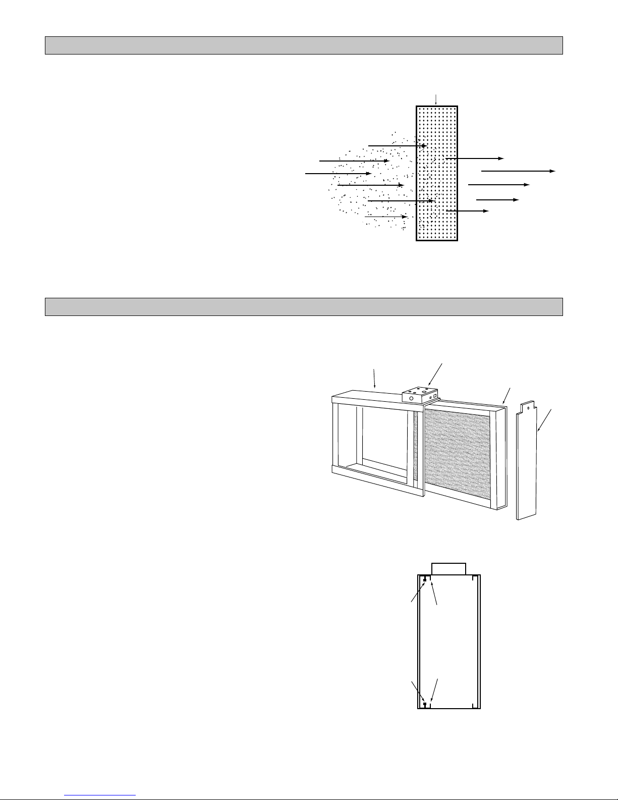
Air Filter OperationAir Filter Operation
Air Filter Operation
Air Filter OperationAir Filter Operation
Unfiltered air flows through the return air ducts and into the
BMAC cabinet. As the air flows across the MERV 8 filter, it
captures dust mites, pollen, mold spores, pet dander and
other contaminants that are 0.3 microns or larger.
The filtered and conditioned air is distributed throughout the
living space through the supply air ducts.
Box Media Air Cleaner ConstructionBox Media Air Cleaner Construction
Box Media Air Cleaner Construction
Box Media Air Cleaner ConstructionBox Media Air Cleaner Construction
The BMAC box media air cleaner is easy to install and
maintain. The basic components of the air cleaner are
detailed below and are shown in figure 2.
NONO
TE:TE:
NO
TE: The BMAC-20C unit has two rails that are clipped
NONO
TE:TE:
inside the cabinet (see Fig 2A). These rails can be removed
to allow the cabinet to accomodate a 5” filter media
(X1152). Use a screwdriver to pop out the clips to remove
the rails. The 5” filter media will slide into the cabinet.
The air filter cabinet is installed in the existing return air duct
system and houses either the supplied filter media on “C”
models or the upgrade components (electronic air cleaner
cells) on the “CE” models.
NOTE NOTE
NOTE - An upgrade kit is available for use with CE
NOTE NOTE
models.(CE models do not have removable rails.) Electronic
air cleaner cells are provided in the kit to replace the
existing MERV 8 media filter.
UNFILTERED AIR IN
AIR FILTER COMPARTMENT
3" FILTER or
5" FILTER
Figure 1Figure 1
Figure 1
Figure 1Figure 1
Junction box
(CE models only)
FILTERED AIR OUT
5" FILTER
DOOR
Figure 2Figure 2
Figure 2
Figure 2Figure 2
Clip
Clip
Removable
Rail
Removable
Rail
Figure 2A
2
Page 3

(
)
Box media air filter locationBox media air filter location
Box media air filter location
Box media air filter locationBox media air filter location
LOCATING THE AIR CLEANERLOCATING THE AIR CLEANER
LOCATING THE AIR CLEANER
LOCATING THE AIR CLEANERLOCATING THE AIR CLEANER
Install the air cleaner in the return air duct (air entering
side) of the furnace or air handler as shown in figure 3.
Install the air cleaner in such a way that the face of the filter
is at a right angle to the air stream. Do not install the air
cleaner in the discharge or supply air duct system.
Allow 25” clearance in front of the air cleaner to accommodate removal of media filters or air cleaner cells. Refer
to figure 4 for dimensions.
If air handler return air, or air entering, opening is not large
enough to accommodate air filter, install a field fabricated
sheet metal transition. Transition reduction should be no
more than 4 inches per linear foot, creating an angle of
approximately 20 degrees. Refer to figure 4.
SPECIAL INSTALLATION NOTES:SPECIAL INSTALLATION NOTES:
SPECIAL INSTALLATION NOTES:
SPECIAL INSTALLATION NOTES:SPECIAL INSTALLATION NOTES:
Atomizing spray-type humidifier (if used) must be installed
downstream of the air cleaner.
UV germicidal light (if used) must be installed a minimum
of 6 ft. from the air cleaner when the two are installed in
direct line of sight to one another. If there is a 90 degree
bend or turn in the air duct between the air cleaner and UV
light, a 3 ft. installation clearance is required between the
two.
AIR FLOW
AIR HANDLER
RETURN AIR/
ENTERING AIR
OPENING
AIR HANDLER
NOT TO EXCEED 20
TRANSITION SECTION
Figure 3
AIR CLEANER
IF NEEDED
AIR FLOW
AIR CLEANER
OPENING
DUCT
Dimension/SpecificationsDimension/Specifications
Dimension/Specifications
Dimension/SpecificationsDimension/Specifications
Filter Media Dimensions NominalFilter Media Dimensions Nominal
Filter Media Dimensions Nominal
Filter Media Dimensions NominalFilter Media Dimensions Nominal
in Inches (Millimeters)in Inches (Millimeters)
in Inches (Millimeters)
in Inches (Millimeters)in Inches (Millimeters)
Model No.Model No.
Model No.
Model No.Model No.
BMAC-12C 16 x 25 x 3 X0581
BMAC-14CE 16 x 26 x 5 X0584
BMAC-20C 20 x 25 x 5 X0586
BMAC-20CE 20 x 26 x 5 X0587
Specifications subject toSpecifications subject to
Specifications subject to
Specifications subject toSpecifications subject to
change without notice.change without notice.
change without notice.
change without notice.change without notice.
Filter SizeFilter Size
Filter Size
Filter SizeFilter Size
(406.4 x 635 x 76.2)
(406.4 x 660.4 x 127)
(508 x 635 x 127) X1152
(508 x 660.4 x 127)
Catalog No.Catalog No.
Catalog No.
Catalog No.Catalog No.
F
D
C
B
A
E
Figure 4
Dimensions in Inches (Millimeters)Dimensions in Inches (Millimeters)
Dimensions in Inches (Millimeters)
Dimensions in Inches (Millimeters)Dimensions in Inches (Millimeters)
Model No.Model No.
Model No.
Model No.Model No.
BMAC-12C 24-5/8 21-29/32 13-1/2 16-15/32 17-13/32 4-15/16
BMAC-14CE 26-3/8 23-5/8 13-9/16 16-15/32 19-15/32 6-15/16
BMAC-20C 24-5/16 22-5/16 17-3/16 20-3/16 21-5/32 6-15/16
BMAC-20CE 26-11/32 23-5/8 17-3/4 20-21/32 23-21/32 6-15/16
AA
A
AA
(625.5) (556.4) (342.9) (418.3) (442.1) (125.4)
(669.9) (600.1) (344.5) (418.3) (494.5) (176.2)
(617.5) (566.7) (436.6) (512.8) (537.4) (176.2)
(669.1) (600.1) (450.9) (524.7) (600.9) (176.2)
BB
B
BB
CC
C
CC
DD
D
DD
EE
E
EE
FF
F
FF
3
Page 4

AIR FLOW
Figure 7
Typical ApplicationsTypical Applications
Typical Applications
Typical ApplicationsTypical Applications
AIR FLOW
Figure 5
BASEMENT AIRBASEMENT AIR
BASEMENT AIR
BASEMENT AIRBASEMENT AIR
HANDLER (LOWBOY)HANDLER (LOWBOY)
HANDLER (LOWBOY)
HANDLER (LOWBOY)HANDLER (LOWBOY)
(Figure 5)(Figure 5)
(Figure 5)
(Figure 5)(Figure 5)
Air cleaner is mounted hori-
zontally in return plenum,
just above air handler.
AIR FLOW
Figure 6
DOWNFLOWDOWNFLOW
DOWNFLOW
DOWNFLOWDOWNFLOW
AIR HANDLER (Figure 6)AIR HANDLER (Figure 6)
AIR HANDLER (Figure 6)
AIR HANDLER (Figure 6)AIR HANDLER (Figure 6)
Air cleaner is mounted hori-
zontally in return duct or plenum, just above air handler.
UPFLOW AIR HANDLERUPFLOW AIR HANDLER
UPFLOW AIR HANDLER
UPFLOW AIR HANDLERUPFLOW AIR HANDLER
(Figure 7)(Figure 7)
(Figure 7)
(Figure 7)(Figure 7)
Side installation. Air cleaner
is mounted vertically, where
return air enters side inlet of
air handler.
UPFLOW AIR HANDLERUPFLOW AIR HANDLER
UPFLOW AIR HANDLER
UPFLOW AIR HANDLERUPFLOW AIR HANDLER
(Figure 8)(Figure 8)
(Figure 8)
(Figure 8)(Figure 8)
Installation beneath air handler.
Air cleaner mounts horizontally,
where return air enters from
below. Raise air handler and
install beneath base.
AIR FLOW
AIR FLOW
HORIZONTAL AIR HANDLERHORIZONTAL AIR HANDLER
HORIZONTAL AIR HANDLER
HORIZONTAL AIR HANDLERHORIZONTAL AIR HANDLER
(Figure 10)(Figure 10)
(Figure 10)
(Figure 10)(Figure 10)
Figure 10
Air cleaner is mounted vertically in
the return duct near air handler.
LESS THAN
7 INCHES
FIGURE 9
OFFSET INSTALLATIONOFFSET INSTALLATION
OFFSET INSTALLATION
OFFSET INSTALLATIONOFFSET INSTALLATION
(Figure 9)(Figure 9)
(Figure 9)
(Figure 9)(Figure 9)
OFFSET
AT LEAST
9 INCHES
Typical use of duct offset to match air cleaner opening.
If duct connection to air handler allows less than nine
inches for mounting the air cleaner, shorten the lateral
trunk, or attach an offset fitting to the elbow.
4
Page 5

InstallationInstallation
Installation
InstallationInstallation
WARNINGWARNING
WARNING
WARNINGWARNING
Risk of property damage, injury or death.Risk of property damage, injury or death.
Risk of property damage, injury or death.
Risk of property damage, injury or death.Risk of property damage, injury or death.
Installation, adjustment, alteration, service and main-Installation, adjustment, alteration, service and main-
Installation, adjustment, alteration, service and main-
Installation, adjustment, alteration, service and main-Installation, adjustment, alteration, service and maintenance must be performed by a qualified servicetenance must be performed by a qualified service
tenance must be performed by a qualified service
tenance must be performed by a qualified servicetenance must be performed by a qualified service
technician.technician.
technician.
technician.technician.
REMOVE OLD FILTER AND DISCARDREMOVE OLD FILTER AND DISCARD
REMOVE OLD FILTER AND DISCARD
REMOVE OLD FILTER AND DISCARDREMOVE OLD FILTER AND DISCARD
(Figure 11)(Figure 11)
(Figure 11)
(Figure 11)(Figure 11)
NOTE: This filter may be mounted in the air handler
cabinet.
CLEAN BLOWER COMPARTMENTCLEAN BLOWER COMPARTMENT
CLEAN BLOWER COMPARTMENT
CLEAN BLOWER COMPARTMENTCLEAN BLOWER COMPARTMENT
NOTE: The air filter cannot remove dirt from blower and
ducts.
INSTALLATIONINSTALLATION
INSTALLATION
INSTALLATIONINSTALLATION
The following is a typical installation of the air cleaner on
an upflow air handler (Figure 7).
1. Place the air cleaner cabinet on the floor. Stand it
upright with the door facing you (Figure 2). If a
horizontal installation is being planned, lay the cabinet
on its side, this will help you to visualize the relative
location of all parts.
2. Unscrew the knob, remove the door (by grasping top
and pulling door away from cabinet) and set it aside.
Remove filter. Set in a safe location until the cabinet
is installed.
3. Set the cabinet next to the air handler (if possible) to
match the opening in the compartment.
If the air handler opening cannot be enlarged, a
transition fitting should be used. (Figure 3).
The cabinet can be attached directly (Figure 12), or a
starting collar can first be fitted to the furnace inlet. A
butt or slip joint can be used.
Securely attach the cabinet to air handler inlet, using
at least two of the mounting holes on each side of the
cabinet.
4. Using butt joint, attach duct (normally an elbow) to the
upstream side of air filter cabinet. (Note the use of the
sheet metal turning vanes inside the elbow to improve
air distribution.) (Figure 13)
NOTE: NOTE:
NOTE: An optional method of attaching duct to the air
NOTE: NOTE:
cleaner cabinet is to modify the cabinet (Figure 14) by
bending the tabs outward at a 90° angle and attaching duct
to tabs.
High Humidity EnvironmentsHigh Humidity Environments
High Humidity Environments: Wrapping cabinet with 2”
High Humidity EnvironmentsHigh Humidity Environments
foil faced insulation (foil on the outside) around the case
(excluding the insulated door) will prevent condensation
on the sides of the unit.
Transition FittingsTransition Fittings
Transition Fittings
Transition FittingsTransition Fittings
If the air duct does not fit the cabinet opening, a transition
fitting should be used. Gradual transitions are preferred
for greatest efficiency. Not more than four inches per
linear foot (approximately 20° angle) should be allowed
(Figure 3).
Figure 11
Air Flow
Optional method
(Bend tabs outward at 90˚ angle)
5. Connect the vertical duct section to the elbow. Wedge
a wood block between floor and elbow for support
(Figure 15).
6. Seal all joints in the return air system downstream
from the air filter with duct tape to prevent dust from
entering the air stream. Tape is usually applied on the
outside of ducts, but may also be applied on the
inside, or both.
7. With the air filter compartment installed, re-install
3” or 5” filter and door. (Figure 2)
NOTENOTE
NOTE: Please remove the plastic bag from the filter
NOTENOTE
media prior to installing the filter media into the air
cleaner cabinet. Proper disposal procedure of
plastic materials should be followed.
5
Turning
Vanes
Figure 13
Figure 14
Page 6

Vertical
Section
Tape All
Joints
Figure 16Figure 16
Figure 16
Figure 16Figure 16
FLOOR
CONDUIT
Wood Block
CACA
UTIONUTION
CA
UTION
CACA
UTIONUTION
Risk of equipment damage and/or high energy usage.Risk of equipment damage and/or high energy usage.
Risk of equipment damage and/or high energy usage.
Risk of equipment damage and/or high energy usage.Risk of equipment damage and/or high energy usage.
Dirty air filters will cause high energy usage and/orDirty air filters will cause high energy usage and/or
Dirty air filters will cause high energy usage and/or
Dirty air filters will cause high energy usage and/orDirty air filters will cause high energy usage and/or
damage to the ventilation system.damage to the ventilation system.
damage to the ventilation system.
damage to the ventilation system.damage to the ventilation system.
Replace filters at recommended intervals.Replace filters at recommended intervals.
Replace filters at recommended intervals.
Replace filters at recommended intervals.Replace filters at recommended intervals.
Figure 15Figure 15
Figure 15
Figure 15Figure 15
For maximum efficiency, your air filter should be
inspected once a month and changed if dirt load is
heavy. The 3” filter should be changed every 6
months and the 5” filter should be changed every
12 months. More frequent changes may be required
in high dust environments.
When changing is required, the following procedure
should be used:
1. Remove door from air filter cabinet by unscrewing
the knob.
Repair Parts and AccessoriesRepair Parts and Accessories
Repair Parts and Accessories
Repair Parts and AccessoriesRepair Parts and Accessories
1
2
4
3
AlAl
ww
aa
ys orys or
Al
w
a
ys or
AlAl
ww
aa
ys orys or
DUCT
AIR CLEANER
2. Remove 3” or 5” filter and throw away.
3. Replace 3” or 5” filter by sliding it into the cabinet.
(Note direction of air flow.)
NOTENOTE
NOTE: Please remove the plastic bag from the filter
NOTENOTE
media prior to installing the filter media into the air
cleaner cabinet. Proper disposal procedure of
plastic materials should be followed.
4. Re-attach door.
WARNINGWARNING
WARNING
WARNINGWARNING
Risk of carbon monoxide poisoning.Risk of carbon monoxide poisoning.
Risk of carbon monoxide poisoning.
Risk of carbon monoxide poisoning.Risk of carbon monoxide poisoning.
Can cause injury or death.Can cause injury or death.
Can cause injury or death.
Can cause injury or death.Can cause injury or death.
Do not operate without access panel in place. Opera-Do not operate without access panel in place. Opera-
Do not operate without access panel in place. Opera-
Do not operate without access panel in place. Opera-Do not operate without access panel in place. Operation of this equipment without the access panel in placetion of this equipment without the access panel in place
tion of this equipment without the access panel in place
tion of this equipment without the access panel in placetion of this equipment without the access panel in place
may cause gas fumes from the heating system to bemay cause gas fumes from the heating system to be
may cause gas fumes from the heating system to be
may cause gas fumes from the heating system to bemay cause gas fumes from the heating system to be
drawn into occupied spaces.drawn into occupied spaces.
drawn into occupied spaces.
drawn into occupied spaces.drawn into occupied spaces.
PARTS LIST FOR BOX MEDIA AIR CLEANERPARTS LIST FOR BOX MEDIA AIR CLEANER
PARTS LIST FOR BOX MEDIA AIR CLEANER
PARTS LIST FOR BOX MEDIA AIR CLEANERPARTS LIST FOR BOX MEDIA AIR CLEANER
When ordering repair parts, always give the following
information as shown in this list.
1. The PART NUMBER
2. The PART DESCRIPTION
3. The MODEL NUMBER of the Box Media Air Cleaner
der bder b
y “Py “P
ARAR
der b
der bder b
y “P
y “Py “P
T NUMBER”T NUMBER”
AR
T NUMBER”
ARAR
T NUMBER”T NUMBER”
. .
.
. .
. .
. .
.
.
. .
. .
Not b Not b
Not b
Not b Not b
y “ITEM NUMBER”y “ITEM NUMBER”
y “ITEM NUMBER”
y “ITEM NUMBER”y “ITEM NUMBER”
UPGRADE!UPGRADE!
UPGRADE!
UPGRADE!UPGRADE!
ELECTRONIC AIR CLEANER KITELECTRONIC AIR CLEANER KIT
ELECTRONIC AIR CLEANER KIT
ELECTRONIC AIR CLEANER KITELECTRONIC AIR CLEANER KIT
Models BMAC-14CE and BMAC-20CE can be upgraded
to a High Efficiency Electronic Air Cleaner. Call your
local Lennox dealer for details.
DescriptionDescription
Description
DescriptionDescription
Air Cleaner X0577 X0578 X0579 X0580
ItemItem
Item
ItemItem
No.No.
No.
No.No.
1 Cabinet X0588 X0589 X0590 X0591
2 Filter X0581 X0584 X0586 X0587
3 Cabinet Door X0592 X0593 X0594 X0595
4 Screw, Fastener X0596 X0596 X0596 X0596
DescriptionDescription
Description
DescriptionDescription
Electronic Air Cleaner Upgrade Kit X0598 X0599
BMAC-12CBMAC-12C
BMAC-12C
BMAC-12CBMAC-12C
DescriptionDescription
Description
DescriptionDescription
BMAC-14CEBMAC-14CE
BMAC-14CE
BMAC-14CEBMAC-14CE
BMAC-BMAC-
BMAC-
BMAC-BMAC-
12C12C
12C
12C12C
BMAC-14CEBMAC-14CE
BMAC-14CE
BMAC-14CEBMAC-14CE
BMAC-20CBMAC-20C
BMAC-20C
BMAC-20CBMAC-20C
Part NumberPart Number
Part Number
Part NumberPart Number
BMAC-BMAC-
BMAC-
BMAC-BMAC-
14CE14CE
14CE
14CE14CE
BMAC-20CEBMAC-20CE
BMAC-20CE
BMAC-20CEBMAC-20CE
BMAC-BMAC-
BMAC-
BMAC-BMAC-
20C20C
20C
20C20C
X1152
BMAC-20CEBMAC-20CE
BMAC-20CE
BMAC-20CEBMAC-20CE
• Contact your local Lennox dealer to order replacement parts. For the Lennox dealer nearest you, dial
1-800-9-LENNOX, or visit www.lennox.com
PART NO. 37-6405APART NO. 37-6405A
PART NO. 37-6405A
PART NO. 37-6405APART NO. 37-6405A
BMAC-BMAC-
BMAC-
BMAC-BMAC-
20C20C
EE
20C
E
20C20C
EE
 Loading...