

Lennox BCK 025, BCK 035, BCK 030, BCK 040, BCK 045 Installation Operating & Maintenance Manual
...Page 1
BALTIC
English
August 2003
INSTALLATION
OPERATING &
MAINTENANCE MANUAL
Page 2
IOM / ROOFTOP BALTIC Series - 0803 - E Page 1
CONTENTS
The present manual applies to the following ROOFTOP versions :
BCK 020 - BCK 025- BCK 030- BCK 035- BCK 040- BCK 045- BCK 050
BHK 020 - BHK 025- BHK 030- BHK 035- BHK 040- BHK 045- BHK 050
BGK 020 - BGK 025- BGK 030- BGK 035- BGK 040- BGK 045- BGK 050
BDK 020 - BDK 025- BDK 030- BDK 035- BDK 040- BDK 045-BDK 050
The technical information and specifications contained in this manual are for reference only. The manufacturer reserves
the right to modify these without warning and without obligation to modify equipment already sold.
IOM MANUAL
Ref. IOM-RT B/0803-E
NOTES FOR UNIT FITTED WITH GAS BURNER:
THE UNIT MUST BE INSTALLED IN ACCORDANCE WITH LOCAL SAFETY
CODES AND REGULATIONS AND CAN ONLY BE USED IN WELL
VENTILLATED AREA.
PLEASE READ CAREFULLY THE MANUFACTURER'S INSTRUCTIONS
BEFORE STARTING THIS UNIT.
THIS MANUAL IS ONLY VALID FOR UNITS DISPLAYING THE FOLLOWING
CODES: GB IR GR DA NO FI IS
In case these symbols are not displayed on the unit, please refer to the
technical documentation which will eventually detail any modifications required
to the installation of the unit in a particular country.
Page 3

Page 2 - IOM / ROOFTOP BALTIC Series - 0803 - E
CONTENTS
INSTALLATION
TRANSPORT - HANDLING ......................................................................................... 4
DIMENSIONS AND WEIGHTS .................................................................................... 5
LIFTING THE UNITS ................................................................................................... 6
PRELIMINARY CHECKS .............................................................................................7
MINIMUM CLEARANCE AROUND THE UNIT ............................................................8
INSTALLATION ON ROOF MOUNTING FRAMES ......................................................9
Adjustable roofcurb .................................................................................................... 10
Multidirectional roofcurb ............................................................................................ 16
Non-adjustable Non-assembled roofcurb ..................................................................22
Curbing and flashing .................................................................................................. 25
ECONOMISER AND EXTRACTION ..........................................................................26
COMMISSIONING 27
BEFORE CONNECTING THE POWER .................................................................... 27
CLIMATIC .................................................................................................................. 27
POWERING THE UNIT .............................................................................................28
RUN TEST ................................................................................................................. 28
COMMISSIONING SHEET 29
VENTILATION 30
BELT TENSION .........................................................................................................32
MOUNTING & ADJUSTING PULLEYS ......................................................................33
AIRFLOW BALANCING ............................................................................................ 34
FILTERS ....................................................................................................................40
FAN STARTER .......................................................................................................... 41
HEATING OPTIONS 42
HOT WATER COILS ..................................................................................................42
ELECTRIC HEATER ..................................................................................................44
GAS BURNERS ......................................................................................................... 45
CLIMATIC CONTROLLER 55
COMMUNICATION LINKS .........................................................................................56
SOFTWARE FEATURES AND LOGIC ......................................................................57
OTHER FEATURES .................................................................................................. 59
CONTROL INTERFACES .......................................................................................... 60
DC50 COMFORT DISPLAY .......................................................................................60
DS50 SERVICE DISPLAY ........................................................................................ 62
DS50 MENU TREE ....................................................................................................64
SAFETY AND ERROR CODES ................................................................................. 73
COMMISSIONING ..................................................................................................... 74
CONTROL INTERFACE CLIMALINK-CLIMALOOK 75
ELECTRICAL WIRING DIAGRAM 83
REFRIGERATION CIRCUIT 93
MAINTENANCE DIAGNOSTIC 95
MAINTENANCE PLAN 98
CONTENTS
Page 4

IOM / ROOFTOP BALTIC Series - 0803 - E Page 3
IMPORTANT NOTICE
IMPORTANT NOTICE
All work on the unit must be carried out by a qualified and authorised employee.
Non-compliance with the following instructions may result in injury or serious accidents.
Work on the unit:
• The unit shall be isolated from the electrical supply by disconnection and locking using the
main isolating switch.
• Workers shall wear the appropriate personal protective equipment (helmet, gloves, glasses,
etc.).
Work on the electrical system:
• Work on electric components shall be performed with the power off (see below) by employees
having valid electrical qualification and authorisation.
Work on the refrigerating circuit(s):
• Monitoring of the pressures, draining and filling of the system under pressure shall be carried
out using connections provided for this purpose and suitable equipment.
• To prevent the risk of explosion due to spraying of coolant and oil, the relevant circuit shall be
drained and at zero pressure before any disassembly or unbrazing of the refrigerating parts
takes place.
• There is a residual risk of pressure build-up by degassing the oil or by heating the exchangers
after the circuit has been drained. Zero pressure shall be maintained by venting the drain
connection to the atmosphere on the low pressure side.
• The brazing shall be carried out by a qualified brazer. The brazing shall comply with the
standard NF EN1044 (minimum 30% silver).
Replacing components:
• In order to maintain CE marking compliance, replacement of components shall be carried out
using spare parts, or using parts approved by Lennox.
• Only the coolant shown on the manufacturer's nameplate shall be used, to the exclusion of all
other products (mix of coolants, hydrocarbons, etc.).
CAUTION:
In the event of fire, refrigerating circuits can cause an explosion and spray coolant gas and oil.
All Baltic units are compliant with the PED directive 97-23-CE.
The following note must be followed carefully.
Page 5
Page 4 - IOM / ROOFTOP BALTIC Series - 0803 - E
TRANSPORT - HANDLING
DELIVERY CHECKS
On receipt of a new equipment please check the following
points. It is the customer's responsibility to ensure that the
products are in good working order:
- The exterior has not been damaged in any way.
- The lifting and handling equipment are suitable for the
equipment and comply with the specifications of the handling
instructions enclosed here-in.
- Accessories ordered for on site installation have been
delivered and are in good working order.
- The equipment supplied corresponds to the order and
matches the delivery note.
If the product is damaged, exact details must be confirmed in
writing by registered post to the shipping company within 48
hours of delivery (working days). A copy of the letter must be
addressed to Lennox and the supplier or distributor for
information purposes. Failure to comply will invalidate any claim
against the shipping company.
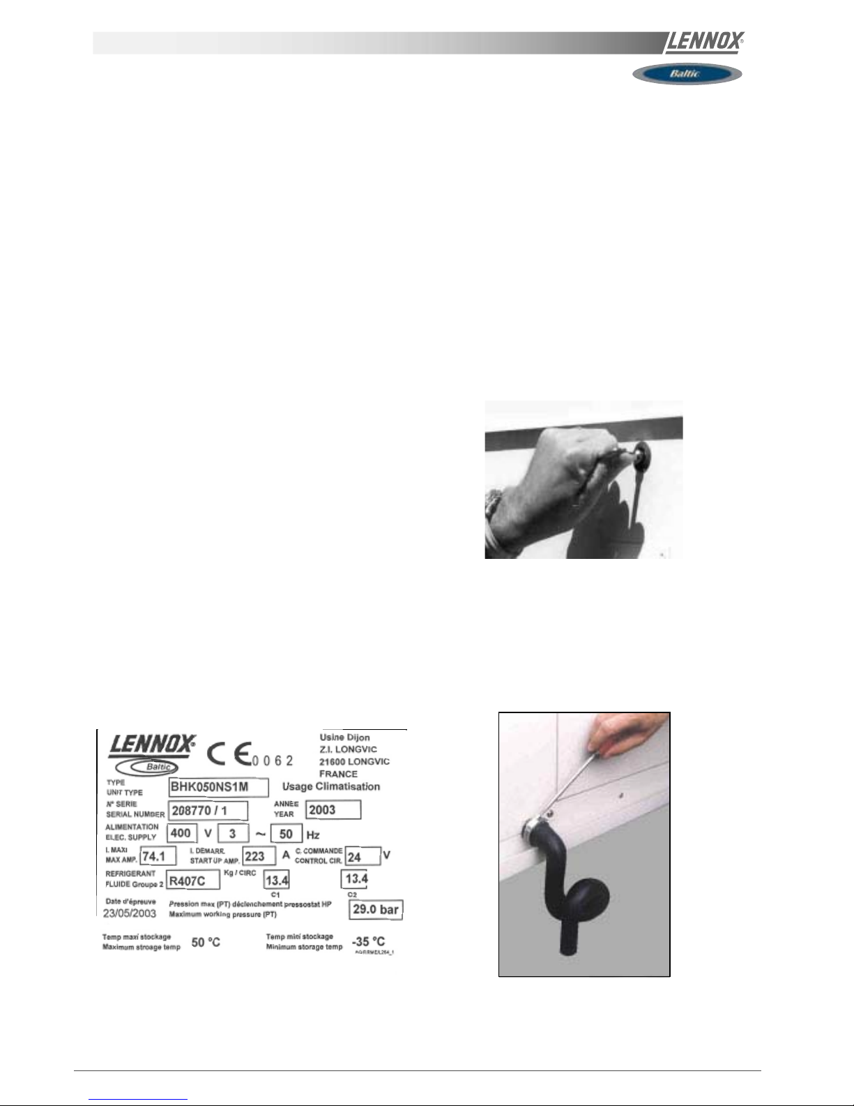
RATING PLATE
The rating plate provides a complete reference for the model
and ensures that the unit corresponds to the model ordered. It
states the electrical power consumption of the unit on startup, its rated power and its supply voltage. The supply voltage
must not deviate beyond +10/-15 %. The start-up power is the
maximum value likely to be achieved for the specified
operational voltage. The customer must have a suitable
electrical supply. It is therefore important to check whether
the supply voltage stated on the unit's rating plate is compatible
with that of the mains electrical supply. The rating plate also
states the year of manufacture as well as the type of refrigerant
used and the required charge for each compressor circuit.
STORAGE
When units are delivered on site they are not always required
immediately and are sometimes put into storage. In the event
of medium to long-term storage, we recommend the following
procedures :
- Ensure that there is no water in the hydraulic systems.
- Keep the heat exchanger covers in position (AQUILUX cover).
- Keep protective plastic film in position.
- Ensure the electrical panels are closed.
- Keep all items and options supplied in a dry and clean place
for future assembly before using the equipment.
MAINTENANCE KEY
On delivery we recommend that you keep the key which is
attached to an eyebolt in a safe and accessible place. This
allows you to open the panels for maintenance and installation
work.
The locks are ¼ turn + then tighter (figure 2).
CONDENSATE DRAINS
The condensate drains are not assembled when delivered and
are stored
in the electrical panel with their clamping collars.
To assemble them, insert them on the condensate tray outlets
and use a screwdriver to tighten the collars (Figure 3).
Fig. 1
Fig. 2
Fig. 3
Page 6
IOM / ROOFTOP BALTIC Series - 0803 - E Page 5
TRANSPORT - HANDLING
A
B
D
C
A
B
D
C
A
B
D
C
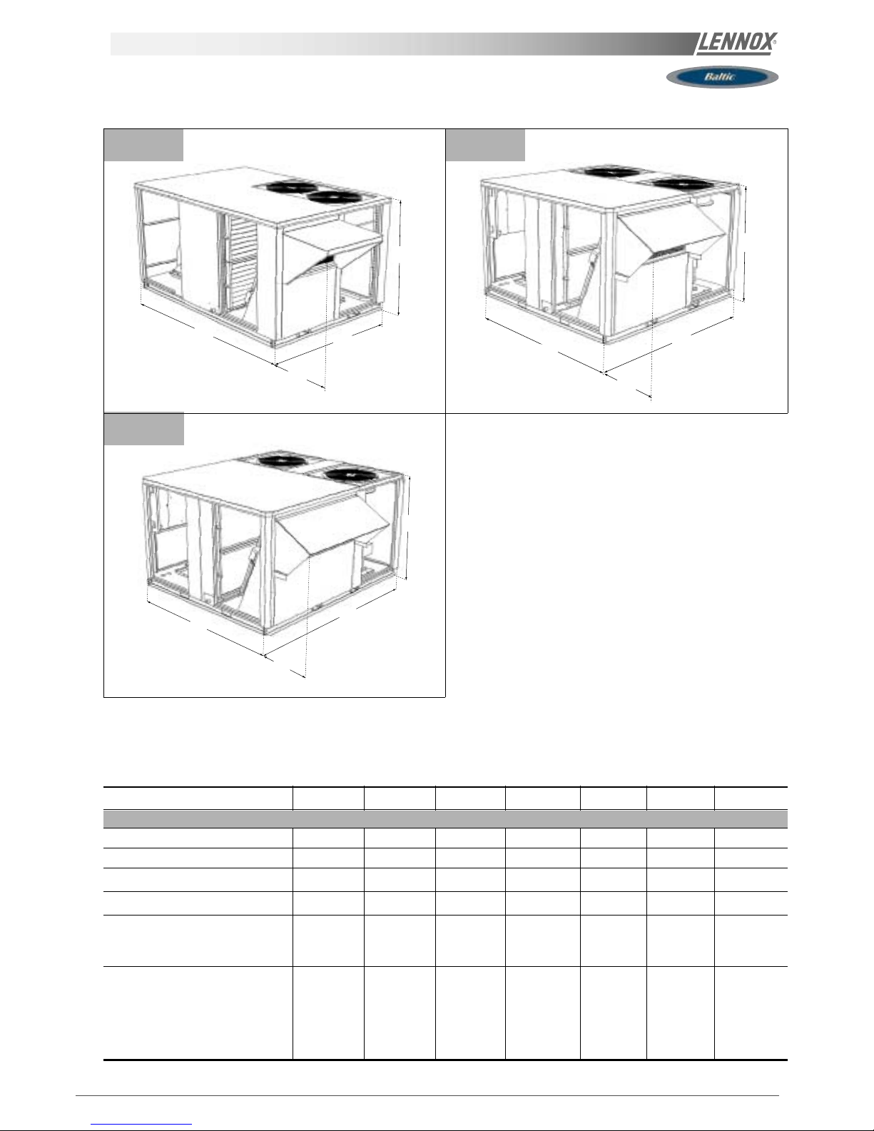
B BOX
D BOX
C BOX
BALTIC BCK/BHK/BGK/BDK 020 025 030 035 040 045 050
View B BOX B BOX C BOX C BOX D BOX D BOX D BOX
A mm 2050 2050 1950 1950 1950 1950 1950
B mm 1418 1418 1913 1913 2233 2233 2233
C mm 1220 1220 1220 1220 1220 1220 1220
D mm 478 478 418 418 418 418 418
Weight of standard units
without hood kg 377 428 501 503 626 630 638
with hood kg 400 451 529 531 659 663 671
Weight of gas units
Standard heat without hood kg 419 472 567 572 709 718 723
Standard heat with hood kg 442 495 595 600 742 751 756
High heat without hood kg 431 484 586 591 730 739 744
High heat with hood kg 454 507 614 619 763 772 777
DIMENSIONS AND WEIGHTS
Fig. 4
Page 7

Page 6 - IOM / ROOFTOP BALTIC Series - 0803 - E
TRANSPORT - HANDLING
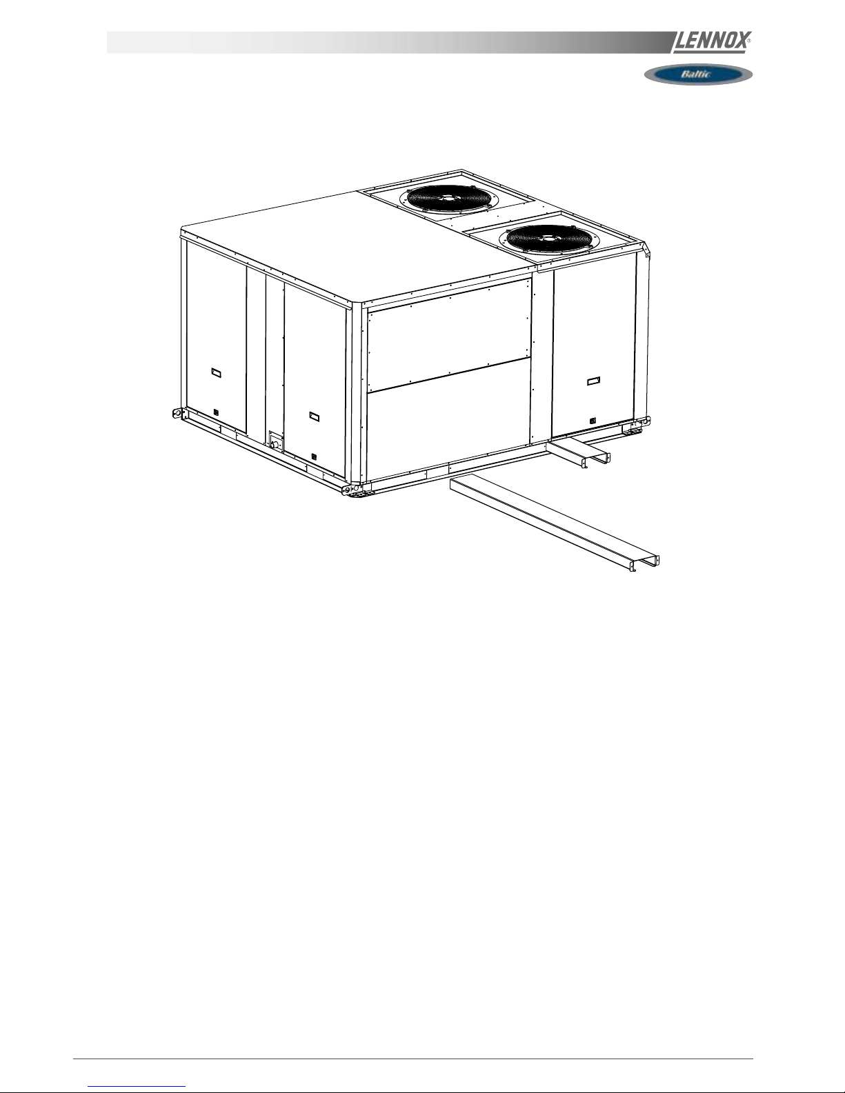
LIFTING B BOX RETRACTABLE LIFTING LUG
LIFTING C BOX LIFTING D BOX
1930
1700
(mini) (mini)
2250
1700
(mini)
(mini)
1850 1410
(mini) (mini)
Fig. 5
Fig. 6
Fig. 7
Fig. 8
Page 8
IOM / ROOFTOP BALTIC Series - 0803 - E Page 7
TRANSPORT - HANDLING
FORKLIFT PROTECTIONS
PRELIMINARY CHECKS
Before installing the equipment, the following points MUST
be checked :
-Have the forklift protections been removed ?
-Is there sufficient space for the equipment?
-Is the surface on which the equipment is to be installed
sufficiently solid to withstand its weight? A detailed study of
the frame must be made beforehand.
-Do the supply and return ductwork openings excessively
weaken the structure?
-Are there any obstructing items which could hinder the
operation of the equipment?
-Does the electrical power available correspond to the
equipment's electrical specifications?
-Is drainage provided for the condensate?
-Is there sufficient access for maintenance?
-Installation of the equipment could require different lifting
methods which may vary with each installation (helicopter or
crane). Have these been evaluated ?
-Ensure that the unit is installed in accordance with the
installation instructions and local applicable codes.
-Check to ensure that the refrigerant lines do not rub against
the cabinet or against other refrigerant lines.
In general, make sure no obstacles (walls, trees or roof ledges)
are obstructing the duct connections or hindering assembly
and maintenance access.
REMOVE FORKLIFT PROTECTIONS
BEFORE INSTALLATION
INSTALLATION REQUIREMENTS
The surface on which the equipment is to be installed must
be clean and free of any obstacles which could hinder the
flow of air to the condensers:
-Avoid uneven surfaces
-Avoid installing two units side by side or close to each other
as this may restrict the airflow to the condensers.
Before installing a packaged Rooftop unit it is important to
understand :
-The direction of prevailing winds.
-The direction and position of air flows.
-The external dimensions of the unit and the dimensions
of the supply and return air connections.
-The arrangement of the doors and the space required to
open them to access the various components.
CONNECTIONS
-Ensure that all the pipe-work crossing walls or roofs are
secured, sealed and insulated.
-To avoid condensation problems, make sure that all pipes
are insulated according to the temperatures of fluids and
type of rooms.
NOTE: The AQUILUX protection sheets fitted to the finned
surfaces must be removed prior to start up.
Fig. 9
Page 9
Page 8 - IOM / ROOFTOP BALTIC Series - 0803 - E
TRANSPORT - HANDLING
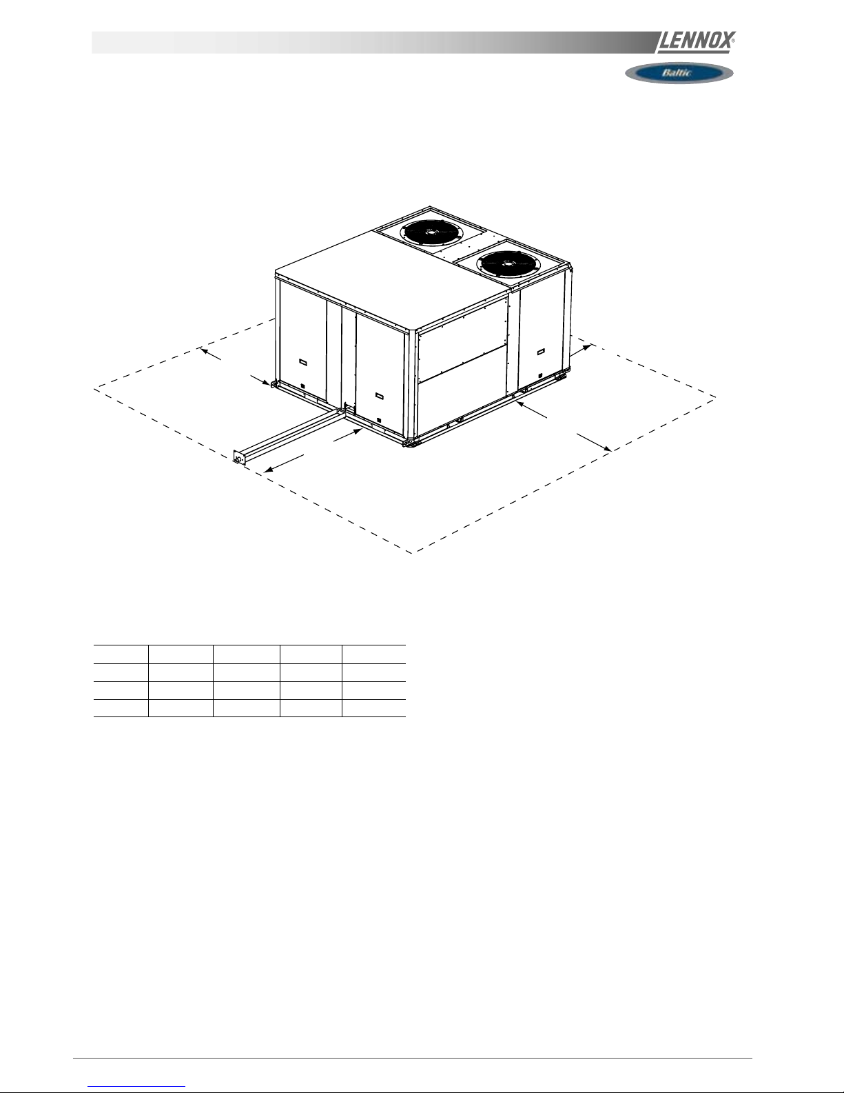
MINIMUM CLEARANCE AROUND THE UNIT
Figure 4 shows the required clearances and service access around the unit.
NOTE : Ensure the fresh air inlet does not face prevailing wind direction.
A
D
B
C
A BCD
B box 1000
(1)
1500
(2)
1500 1000
C box 1200
(1)
1500
(2)
1500 1000
D box 1400
(1)
1500
(2)
1500 1000
(1)Add one meter to this distance if units is fitted with Gas Burner.
(2) Double distance if unit fitted with extraction.
Fig. 10
Page 10
IOM / ROOFTOP BALTIC Series - 0803 - E Page 9
INSTALLATION ON A ROOF MOUNTING FRAMES
As levels are adjustable, observe the following
recommendations when installing the equipment.
Above all, ensure that all the adjustable returns are facing
outward ( figure 11). They are usually turned inside-out for
transport.
Place the roof mounting frame on the trimmer beam by first
lining up the inlet and the outlet opening. ("2"- figure 12)
After levelling the frame, secure the adjustable returns on
the trimmer (figure 13).
It is important to centre the unit on the roof frame.
2
Fig. 12
Fig. 13
Fig. 11
1
Page 11
Page 10 - IOM / ROOFTOP BALTIC Series - 0803 - E
INSTALLATION ON A ROOF MOUNTING FRAMES
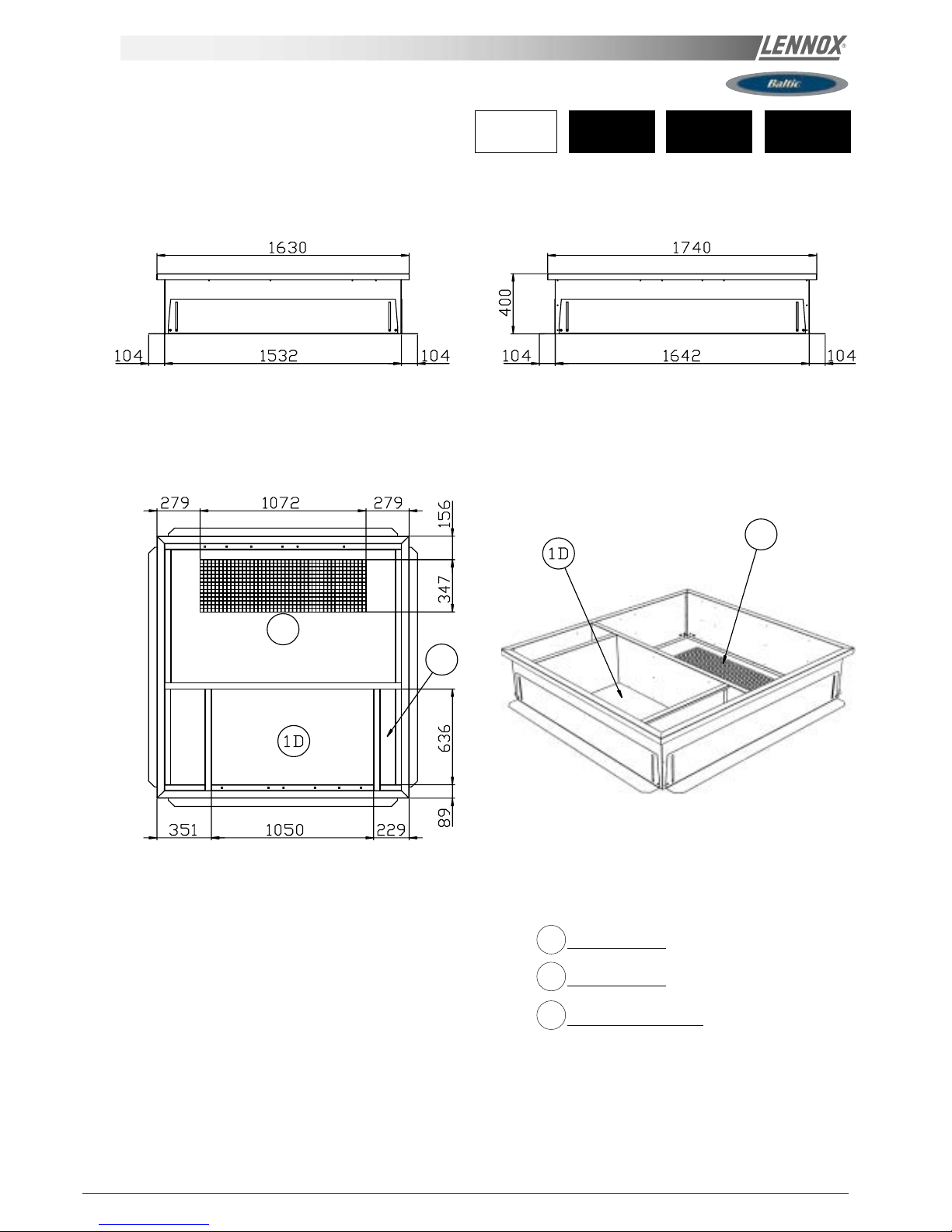
D
D
2D
2D
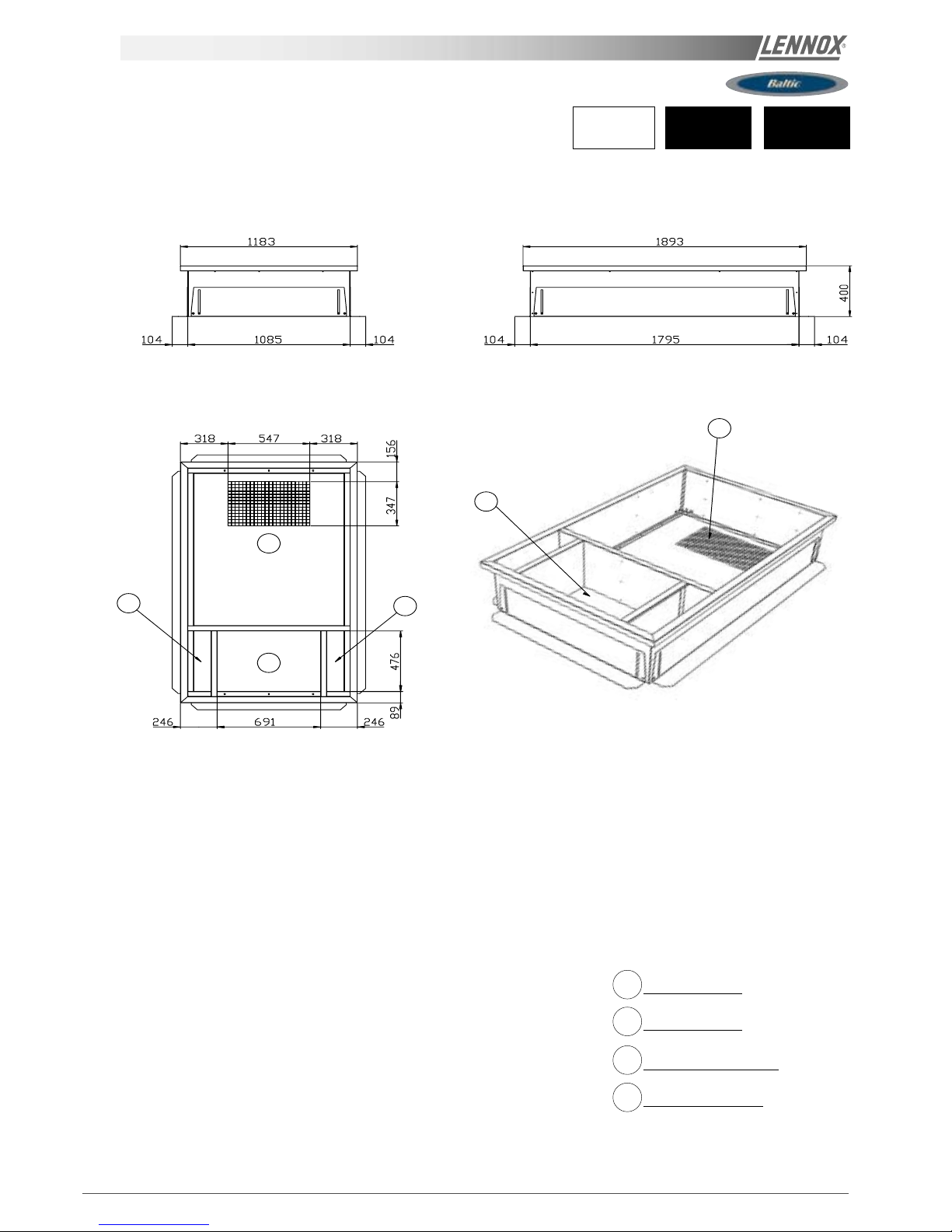
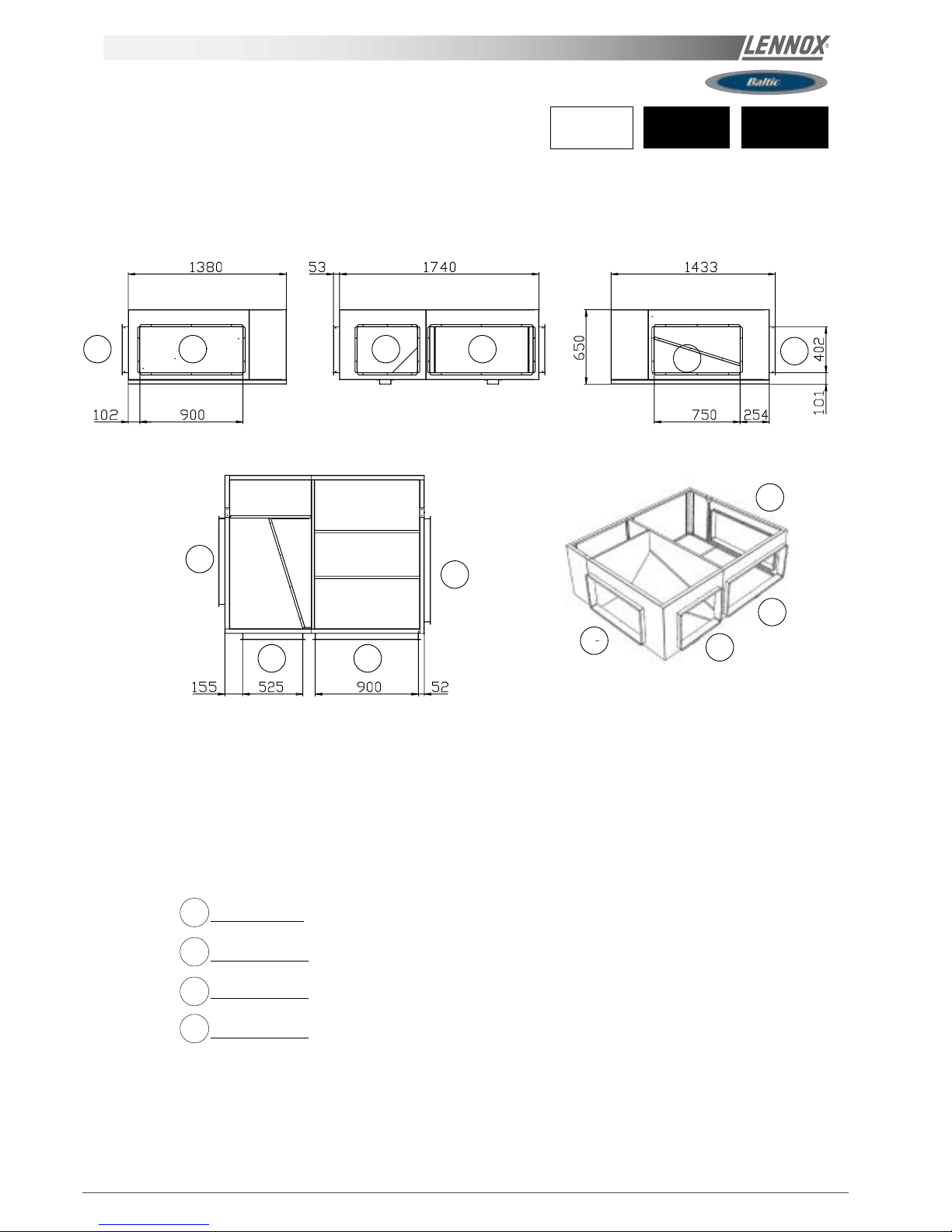
Roof opening 1795 x 1085
2D
Return Air
8
Main Power Entry
1D
Down Supply Air
020 025
BCK
BHK
(*) without auxiliary electric heater
without hot water coil.
ADJUSTABLE ROOFCURB DRAWINGS
Page 12
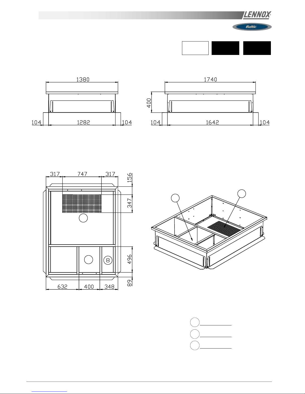
IOM / ROOFTOP BALTIC Series - 0803 - E Page 11
1D
1D
2D
2D
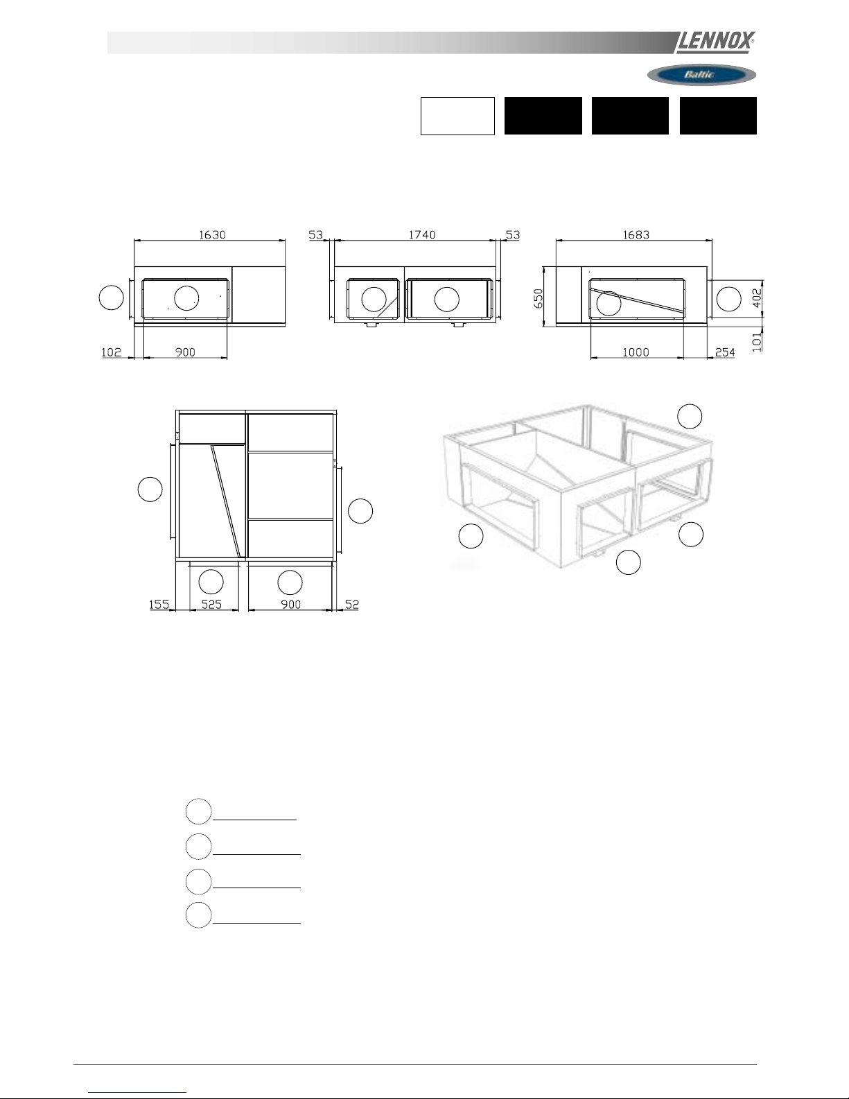
Roof opening 1642 x 1282
030 035
BCK
BHK
8
Main Power Entry
2D
Front supply air
1D
Down Supply Air
(*) without auxiliary electric heater
without hot water coil.
INSTALLATION ON A ROOF MOUNTING FRAMES
ADJUSTABLE ROOFCURB DRAWINGS
Page 13
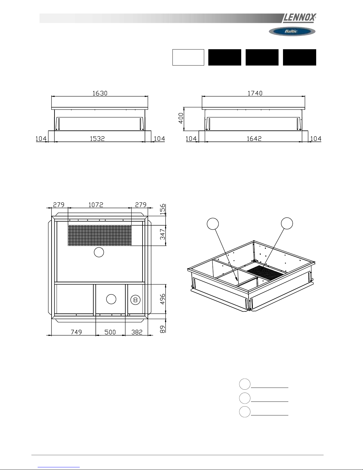
Page 12 - IOM / ROOFTOP BALTIC Series - 0803 - E
045 050040
BCK
BHK
1D
1D
2D
2D
8
Main Power Entry
2D
Front supply air
1D
Down Supply Air
Roof opening 1642 x 1532
(*) without auxiliary electric heater
without hot water coil.
INSTALLATION ON A ROOF MOUNTING FRAMES
ADJUSTABLE ROOFCURB
DRAWINGS
Page 14
IOM / ROOFTOP BALTIC Series - 0803 - E Page 13
4D
5D
1D
2D
2D
1D
020 025
BGK
BDK
4D
5D
Down hot water Entry
2D
DownReturn Air
1D
Down Supply Air
Down main power entry
Roof opening 1795 x 1085
(*) This roofcurb is also necessary for all cooling only or
heatpump rooftop with auxiliary electric heater or hot
water coil.
INSTALLATION ON A ROOF MOUNTING FRAMES
ADJUSTABLE ROOFCURB DRAWINGS
Page 15
Page 14 - IOM / ROOFTOP BALTIC Series - 0803 - E
2D
2D
4D
030 035
BGK
BDK
4D
2D
DownReturn Air
1D
Down Supply Air
Down main power entry
Roof opening 1642 x 1282
(*) This roofcurb is also necessary for all cooling only or
heatpump rooftop with auxiliary electric heater or hot
water coil.
INSTALLATION ON A ROOF MOUNTING FRAMES
ADJUSTABLE ROOFCURB DRAWINGS
Page 16
IOM / ROOFTOP BALTIC Series - 0803 - E Page 15
4D
2D
2D
045 050040
BGK
BDK
4D
2D
DownReturn Air
1D
Down Supply Air
Down main power entry
Roof opening 1642 x 1532
(*) This roofcurb is also necessary for all cooling only or heatpump
rooftop with auxiliary electric heater or hot water coil.
INSTALLATION ON A ROOF MOUNTING FRAMES
ADJUSTABLE ROOFCURB
DRAWINGS
Page 17
Page 16 - IOM / ROOFTOP BALTIC Series - 0803 - E
2F
2F'
2F'
2F
1F'
1F
2F'
2F
2F'
1F
1F
1F
1F'
1F'
INSTALLATION ON A ROOF MOUNTING FRAMES
020 025
BCK
BHK
1F'
Front supply air
2F
2F'
Front return air
1F
Front supply air
WARNING : ONLY ONE OF THE 4 FOLLOWINGS POSSIBILITIES :
2F - 1F / 2F - 1F'
2F' - 1F / 2F' - 1F'
Front return air
(*) without auxiliary electric heater
without hot water coil.
MULTIDIRECTIONAL HORIZONTAL ROOFCURB
Page 18
IOM / ROOFTOP BALTIC Series - 0803 - E Page 17
2F'
2F
1F
1F' 1F 1F'
1F'
1F
2F'
2F
1F'
1F
2F'
2F
035030
BCK
BHK
1F'
Front supply air
2F
2F'
Front return air
1F
Front supply air
WARNING : ONLY ONE OF THE 4 FOLLOWINGS POSSIBILITIES :
2F - 1F / 2F - 1F'
2F' - 1F / 2F' - 1F'
Front return air
(*) without auxiliary electric heater
without hot water coil.
INSTALLATION ON A ROOF MOUNTING FRAMES
MULTIDIRECTIONAL HORIZONTAL ROOFCURB
Page 19
Page 18 - IOM / ROOFTOP BALTIC Series - 0803 - E
2F' 2F 1F
2F'
1F 1F'
1F'
1F
2F'
2F
1F'
1F
2F'
2F
045 050040
BCK
BHK
1F'
Front supply air
2F
2F'
Front return air
1F
Front supply air
WARNING : ONLY ONE OF THE 4 FOLLOWINGS POSSIBILITIES :
2F - 1F / 2F - 1F'
2F' - 1F / 2F' - 1F'
Front return air
(*) without auxiliary electric heater
without hot water coil.
INSTALLATION ON A ROOF MOUNTING FRAMES
MULTIDIRECTIONAL HORIZONTAL
ROOFCURB
Page 20

IOM / ROOFTOP BALTIC Series - 0803 - E Page 19
020 025
BGK
BDK
2F'
2F
1F
2F'
1F
1F'
1F'
1F
2F'
2F
1F'
1F
2F'
2F
1F'
Front supply air
2F
2F'
Front return air
1F
Front supply air
WARNING : ONLY ONE OF THE 4 FOLLOWINGS POSSIBILITIES :
2F - 1F / 2F - 1F'
2F' - 1F / 2F' - 1F'
Front return air
(*) This roofcurb is also necessary for all cooling only or
heatpump rooftop with auxiliary electric heater or hot
water coil.
INSTALLATION ON A ROOF MOUNTING FRAMES
MULTIDIRECTIONAL HORIZONTAL ROOFCURB
Page 21
Page 20 - IOM / ROOFTOP BALTIC Series - 0803 - E
030 035
BGK
BDK
1F'
Front supply air
2F
2F'
Front return air
1F
Front supply air
WARNING : ONLY ONE OF THE 4 FOLLOWINGS POSSIBILITIES :
2F - 1F / 2F - 1F'
2F' - 1F / 2F' - 1F'
Front return air
2F' 2F 1F 2F'
1F
1F'
1F'
1F 2F'
2F
1F'
1F
2F'
2F
(*) This roofcurb is also necessary for all cooling only
or heatpump rooftop with auxiliary electric heater or
hot water coil.
INSTALLATION ON A ROOF MOUNTING FRAMES
MULTIDIRECTIONAL HORIZONTAL ROOFCURB
Page 22
IOM / ROOFTOP BALTIC Series - 0803 - E Page 21
045 050040
BGK
BDK
2F'
2F
1F
2F'
1F
1F'
2F
2F'
1F
1F'
2F
2F'1F
1F'
1F'
Front supply air
2F
2F'
Front return air
1F
Front supply air
WARNING : ONLY ONE OF THE 4 FOLLOWINGS POSSIBILITIES :
2F - 1F / 2F - 1F'
2F' - 1F / 2F' - 1F'
Front return air
(*) This roofcurb is also necessary for all cooling only or heatpump
rooftop with auxiliary electric heater or hot water coil.
INSTALLATION ON A ROOF MOUNTING FRAMES
MULTIDIRECTIONAL HORIZONTAL
ROOFCURB
Page 23

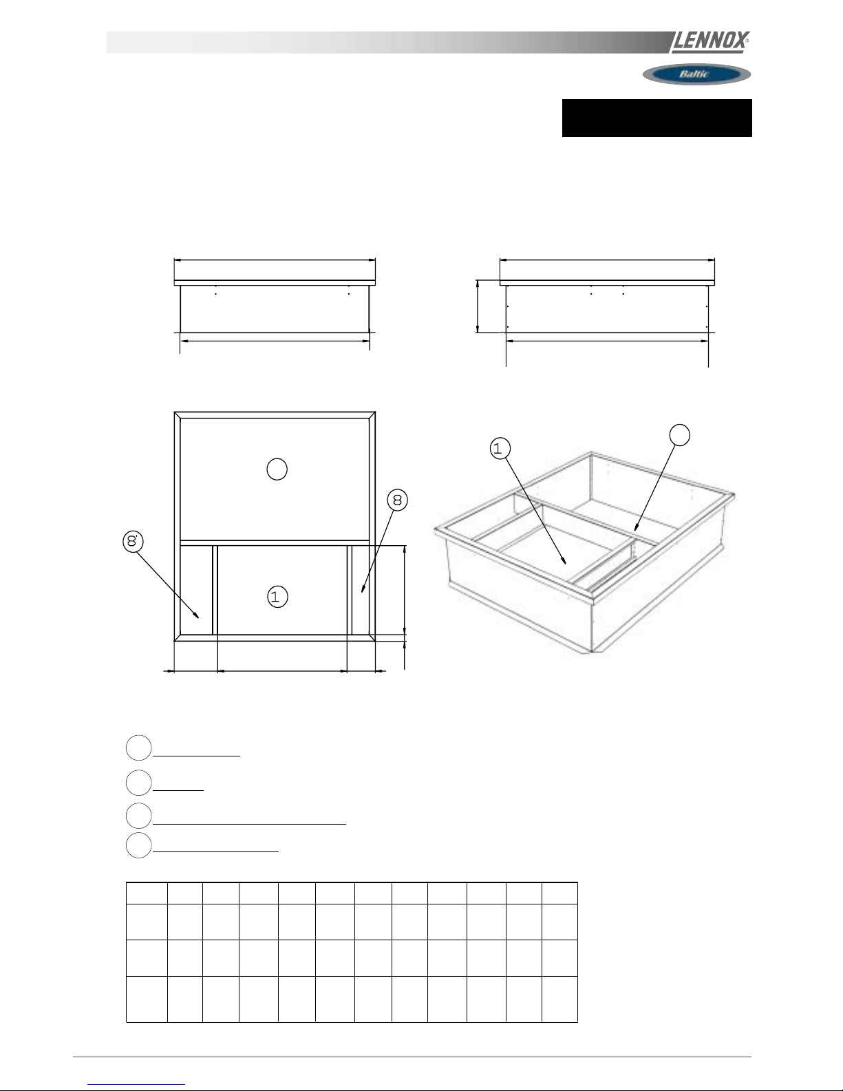
Page 22 - IOM / ROOFTOP BALTIC Series - 0803 - E
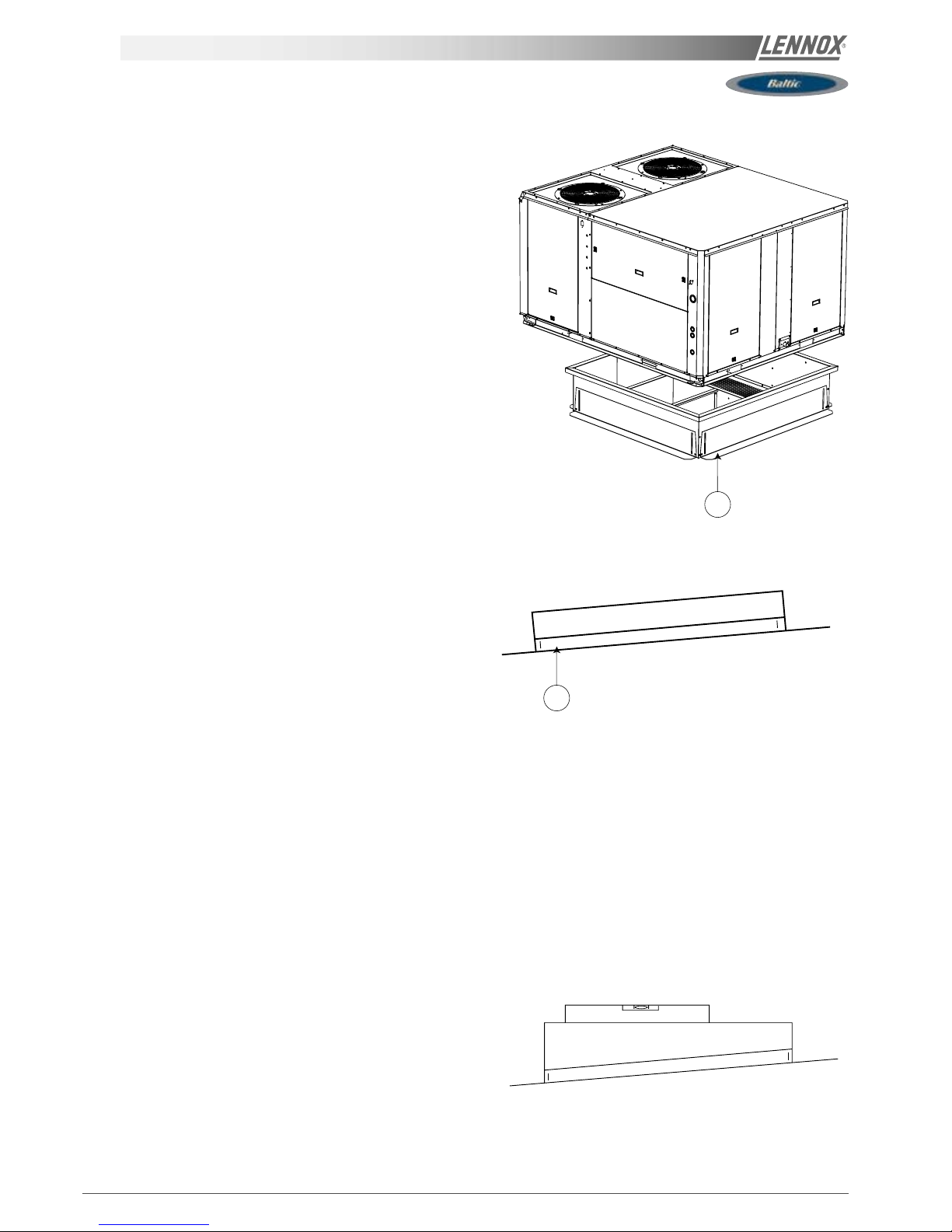
INSTALLATION ON A ROOF MOUNTING FRAME
NON ADJUSTABLE NON ASSEMBLED ROOFCURB INSTALLATION
FRAME PARTS IDENTIFICATION
Figure 14 shows the different parts for identification
INSTALLATION
The roof mounting frame provides support when the units are installed in down-flow configurations.
The non adjustable, non assembled roof mounting frame can be installed directly on decks having adequate structural
strength or on roof supports under deck. See page 23 for frame dimensions, location of supply and return air opening
NOTE: frame assembly must be installed flat, levelled within 5mm per linear meter in any direction.
UNIT FLOOR
UNIT FLOOR
INSULATION
UNIT SUPPORT RAIL
ROOFCURB
AIR DUCT
Fig. 15
Fig. 14
Page 24
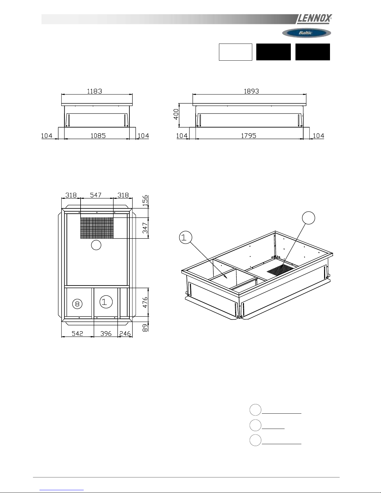
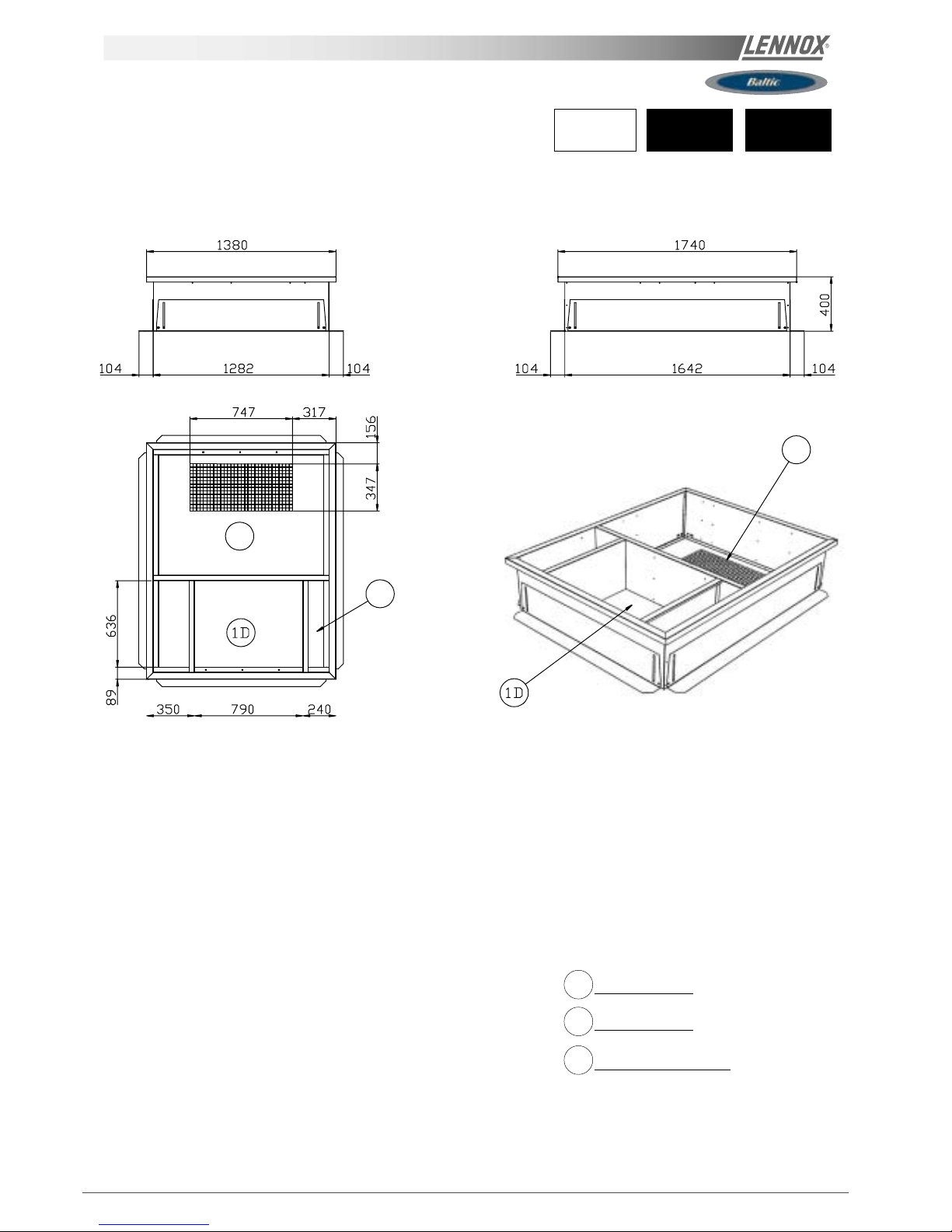
IOM / ROOFTOP BALTIC Series - 0803 - E Page 23
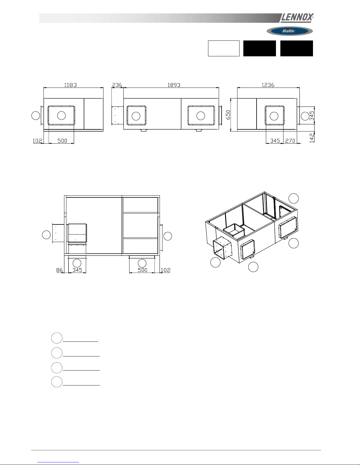
A
J
I
CF
G
H
E
D
B
D
D
2D
2D
1D
Down Supply Air
2D
Return Air
8
Main Power Entry 030-035-040-045-050
BCK = Cooling only unit
BHK = Heat pump unit
BGK = Cooling only unit with gas fired heating
BDK = Heat pump unit with gas fired heating
(*) Non adjustable, non assembled roofcurb.
8'
Main Power Entry 020-025
Roof opening I x J
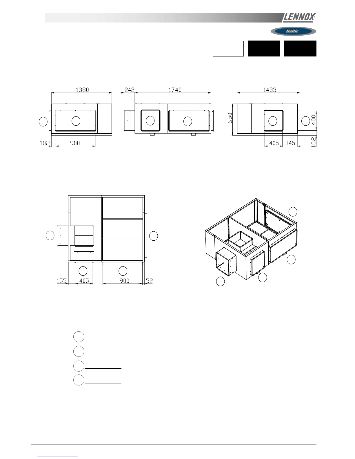
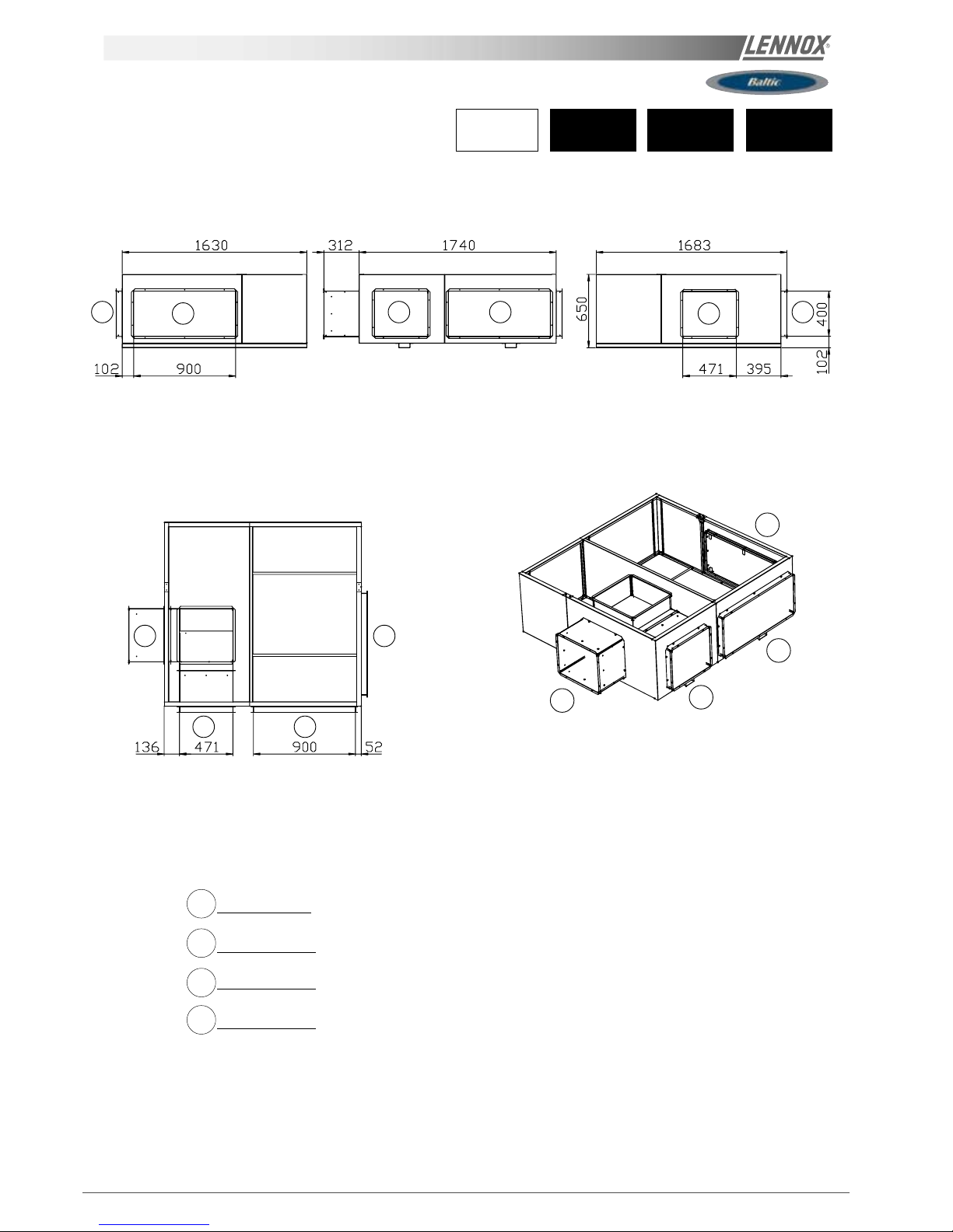
Type Taille A B C D E F G H I J
All 020
1183 1893 691 400 246 246 515 50 1783 1083
025
All 030
1380 1740 790 400 351 240 675 50 1640 1280
035
All 040
045 1630 1740 1050 400 352 229 675 50 1640 1530
050
All units
INSTALLATION ON A ROOF MOUNTING FRAME
NON ADJUSTABLE HORIZONTAL ROOFCURB
Page 25
Page 24 - IOM / ROOFTOP BALTIC Series - 0803 - E
INSTALLATION ON A ROOF MOUNTING FRAME
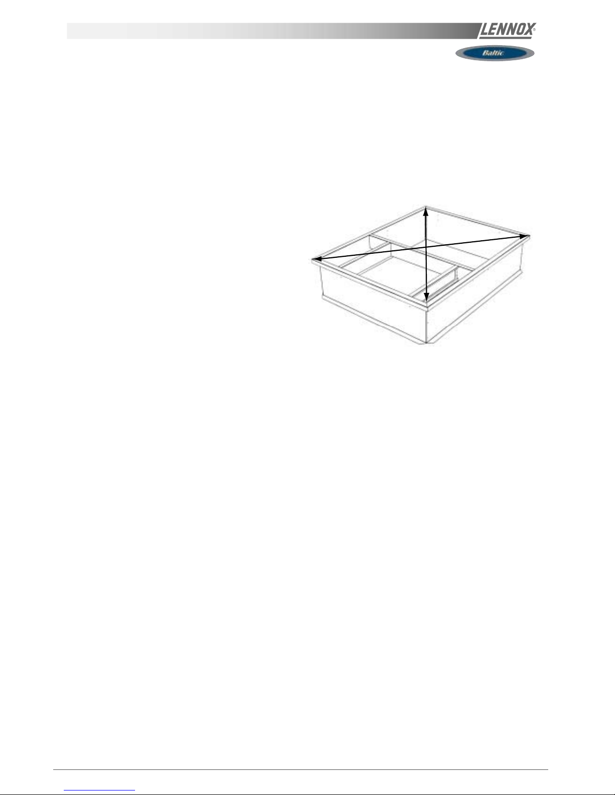
ASSEMBLY
The frame is supplied as a single package and shipped folded down for ease of transport and handling. It is easy field
assembled as all parts required are supplied with the frame.
-Measure frame diagonally from corner to corner as shown
in figure 16. These Dimensions must be equal in order for
the fame to be square.
-It is extremely important to sight frame from all corner to
ensure it is not twisted across. Shim frame under any low
side. The maximum slope tolerance is 5mm per linear meter
in any direction.
-After the frame has been squared, straightened and
shimmed, weld or secure the frame to the roof deck.
NOTE: It must be securely fastened to the roof as per local
codes and regulations.
SECURING THE FRAME
To ensure proper mating with units (figure 15), it is mandatory that the roof mounting frame be squared to roof structure as
follows:
-With frame positioned levelled in the desired location on roof trusses, tack weld corner of frame.
Fig. 16
Page 26
IOM / ROOFTOP BALTIC Series - 0803 - E Page 25
y
y
y
y
y
y
y
y
y
y
y
y
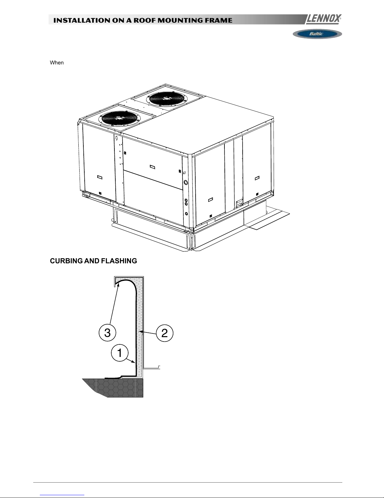
3
1
2
INSTALLATION ON A ROOF MOUNTING FRAME
CURBING AND FLASHING
When the frame is correctly positioned. It is essential to secure the assembly with a disconnected stitched welded seam (20 to
30mm every 200mm) along the outside or by using an alternative method.
Before installing the equipment, make sure that seals are not
damaged and check that the unit is secured to the mounting
frame. Once in position, the bottom of the equipment must be
horizontal.
The installer must comply to local authority standards and
specifications.
Outside of frame must be insulated with rigid type insulation;
We recommend a minimum of 20 mm thick insulation (2 figure
18).
Check that the insulation is continuous, counter flash and seal
around the frame as shown in (1-figure 18).
CAUTION : To be effective, the upstream must end below the
drop edge (3 - figure 18).
Where pipes and electrical conduits extend through the roof,
flashing must conform to local codes of practice.
Fig. 18
Fig. 17
Page 27
Page 26 - IOM / ROOFTOP BALTIC Series - 0803 - E
Economiser
Free cooling can be provided through the use of fresh air where
appropriate rather than cooling excessive amounts of return
air.
The economiser is factory fitted and tested prior to shipment.
It includes two dampers operating from a 24V actuator
Rain hood
It also includes a factory fitted rain hood . Hoods is folded
during transportation to limit risks of damage and must be
unfolded on site as shown below:
Extraction
Installed with economiser assembly, the gravity exhaust
dampers relieve the pressure when outside air is introduced
into the system.
When large amount of fresh air is introduced into the system
power exhaust fans can be used to equalise the pressures.
The extraction fan runs when return air dampers are being
closed and supply air blower is in operation. The extraction
fan runs when outdoor air dampers are at least 50% open
(adjustable value) It is overload protected.
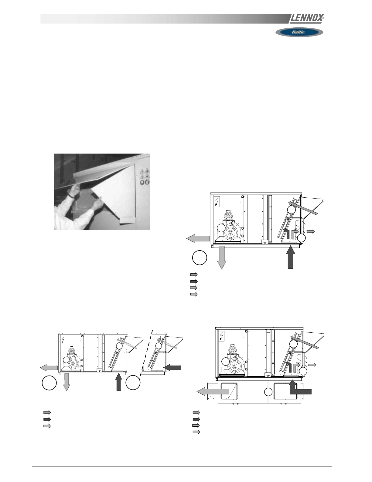
NOTE: When horizontal flow configuration is required, the
multidirectional roofcurb will be installed
HORIZONTAL FLOW WITH MULTIDIRECTIONAL
ROOFCURB
VERTICAL FLOW STANDARD INSTALLATION
1 Supply fan
2 Economiser damper
3 Exhaust damper or
Exhaust damper + exhaust fan
4 Multidirectional roofcurb
Fresh air
Return air
Supply air
Exhaust air
1
4
2
3
ECONOMISER AND EXTRACTION
1
2
3
1 Supply fan
2 Economiser damper
Fresh air
Return air
1 Supply fan
2 Economiser damper
3 Exhaust damper or
Exhaust damper + exhaust fan
Fresh air
Return air
Supply air
Exhaust air
VERTICAL FLOW WITH EXTRACTION
2
1
2
OR
OR
OR
Supply air
Fig. 19
Fig. 20
Fig. 21
Fig. 22
Page 28
IOM / ROOFTOP BALTIC Series - 0803 - E Page 27
Fig. 25
COMMISSIONING
THIS WORK MUST ONLY BE CARRIED
OUT BY TRAINED REFRIGERATION
ENGINEERS
FILL THE COMMISSIONNING SHEET AS
YOU GO ALONG
BEFORE CONNECTING THE POWER:
- Ensure that the power supply between the building and the
unit meets local authority standards and that the cable
specification satisfies the start-up and operating conditions.
ENSURE THAT THE POWER SUPPLY
INCLUDES 3 PHASES AND A NEUTRAL
- Check the following wire connections for tightness: Main
switch connections, mains wires linked to the contactors and
circuit breakers and the cables in the 24V control supply
circuit.
- Ensure that all drive motors are secure.
- Ensure that the adjustable pulley blocks are secure and
that the belt is tensioned with the transmission correctly
aligned. Refer to the next section foe details.
- Using the electrical wiring diagram, check the conformity of
the electrical safety devices (circuit breaker settings,
presence and rating of fuses).
- Check the temperature probe connections.
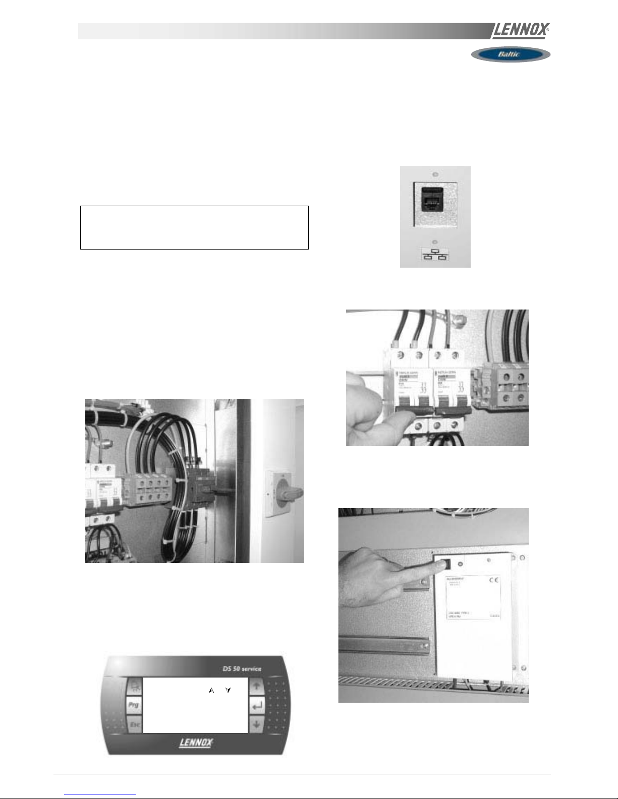
STARTING THE UNIT
At this point the unit circuit breakers should be open
You will need a DS50 maintenance controller or Climalook
with appropriate Interface.
The jumpers are factory set and the configuration switches
are adjusted depending on the option the type of unit.
Connecting the CLIMATIC diplays.
Close the 24V Control Circuit breakers.
The CLIMATIC 50 starts after 30s
Reset the DAD photo (If fitted)
Check and adjust the control settings.
Refer to the control section in this manual to adjust the
different parameters
LanguageLanguage
LanguageLanguage
Language
or
ENGLISHENGLISH
ENGLISHENGLISH
ENGLISH
RT 050.001RT 050.001
RT 050.001RT 050.001
RT 050.001
BIOS 0000 Boot 0000BIOS 0000 Boot 0000
BIOS 0000 Boot 0000BIOS 0000 Boot 0000
BIOS 0000 Boot 0000
Fig. 23
Fig. 24
Fig. 26
Fig. 27
Page 29
Page 28 - IOM / ROOFTOP BALTIC Series - 0803 - E
POWERING THE UNIT
- Power up the unit by closing the isolator switch (if fitted).
- At this point the blower should start unless the climatic
does not energise the contactor. In this particular case the
blower can be forced by bridging the port NO7 and C7 on
connector J14 on the Climatic. Once the fan is running
check the rotation direction. Refer to the rotation arrow
located on the fan.
- The fans and compressors direction of rotation is checked
during the end of line test. They should therefore all turn in
either the right or wrong direction.
NOTE : A compressor rotating in the wrong direction will
fail.
- If the fan turns in the wrong direction, disconnect the main
power supply to the machine at the building's mains switch,
reverse two phases and repeat the above procedure.
- Close all circuit breakers and power up the unit, remove
the bridge on connector J14 if fitted.
- If now only one of the components rotates in the wrong
direction, disconnect the power supply at the machine's
isolator switch (if fitted) and reverse two of the component's
phases on the terminal within the electrical panel.
- Check the current drawn against the rated values, in
particular on the supply fan (ref. page 34).
- If the readings on the fan are outside the specified limits,
this usually indicates excessive air flow which will affect the
life expectancy and the thermodynamic performances of the
unit. This will also increase the risks of water ingress into
the unit. Refer to the "Air Flow Balancing" section to correct
the problem.
At this point attach the manometers to the refrigerant circuit.
RUN TEST
Start unit in cooling mode
Thermodynamic readings using manometers and
prevailing environmental conditions
No rated values are given here. These depend on the
climatic conditions both outside and inside the building
during operation. However, an experienced refrigeration
engineer will be able to detect any abnormal machine
operation.
Safety test
- "Dirty filter" detection test : vary the set-point value (menu
3413 on DS50) in respect to the air pressure value. Ob-
serve the response of the CLIMATIC™.
- Same procedure for detecting "Missing Filter" (menu
3412) or "Air Flow Detection" ( menu 3411).
- Check the smoke detection function (if fitted).
- Check the Firestat by pressing the test button(if fitted).
- Disconnect the circuit breakers of the capacitor fans and
check the high pressure cut-out points on different
refrigerant circuits.
Reverse cycle test
This test is designed to check the good operation of the 4way reversing valves on heat pump reversible systems.
Start the reverse cycle by adjusting the cold or hot
temperature threshold data according to the indoor and
outdoor conditions at the time of test (menu 3320).
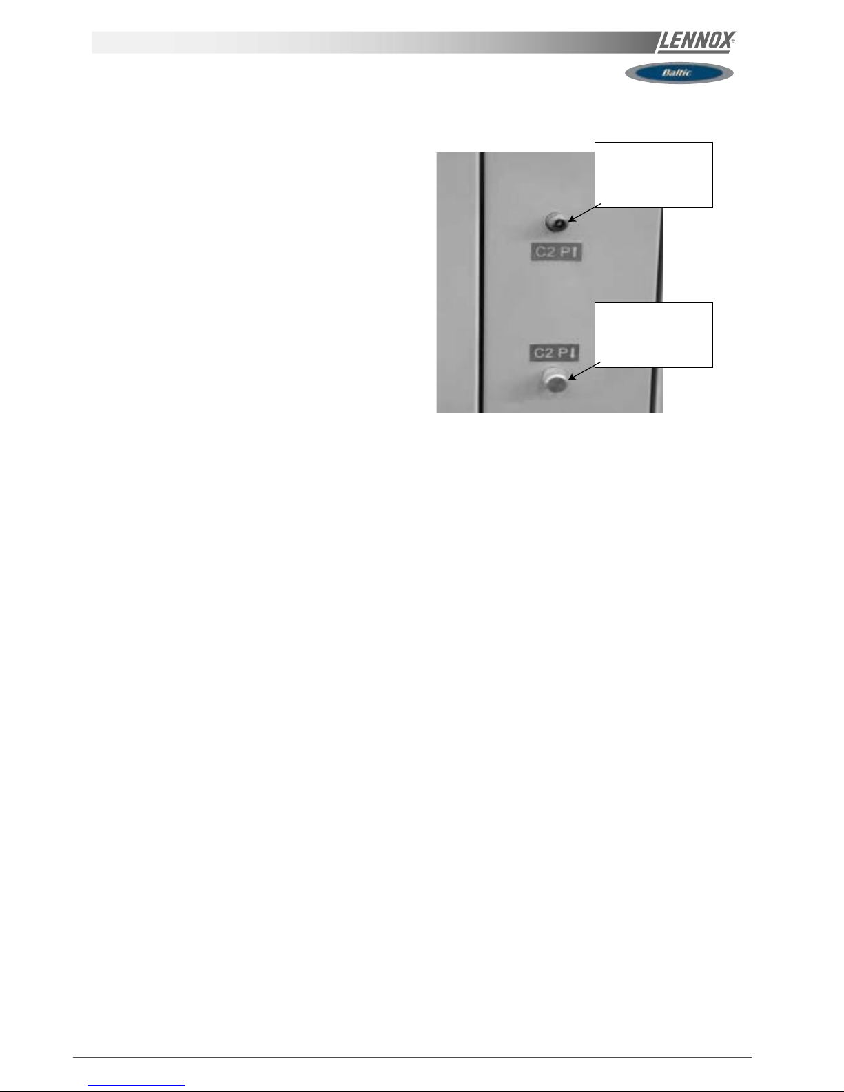
HIGH PRESSURE
CONNECTION CIRCUIT
N°2
LOW PRESSURE
CONNECTION CIRCUIT
N°2
COMMISSIONING
Fig. 28
Page 30
IOM / ROOFTOP BALTIC Series - 0803 - E Page 29
COMMISSIONING report
(4) SUPPLY BLOWER SECTION / VENTILATION TRAITEMENT
Type / Type:
Power displayed on plate / Puissance affichée sur la plaque:
Voltage displayed on plate / Tension affichée sur la plaque:
Current displayed on plate / Intensité affichée sur la plaque:
KW
V
A
N°1
……………………
……………………
……………………
N°2
……………………
……………………
……………………
Fan Type / Type de Ventilateur: Forward / Action
Backward / Réaction
Forward / Action
Backward / Réaction
Displayed Belt Length / Longueur Courroie affichée: mm …………………… ……………………
Tension Checked/ Tension Vérifiée: Yes/Oui No/ Non Yes/Oui No/ Non
Alignment Checked / Alignement Vérifié: Yes/Oui No/ Non Yes/Oui No/ Non
Motor Pulley Dia/ Poulie Moteur Dia: D
M
mm …………………… ……………………
Fan Pulley Dia/ Poulie Ventilateur Dia: D
P
mm …………………… ……………………
Fan Speed / Vitesse rotation Ventilateur = Motor rpm x DM / D
P
Averaged Measured Amps / Intensité Mesurée moyenne:
rpm
A
……………………
……………………
……………………
……………………
Shaft Mechanical Power (Refer to airflow balancing)
Puissance Mécanique à l’Arbre (Voir section réglage débit)
W …………………… ……………………
Operating point checked / Vérif. Point de fonctionnement: Yes/Oui No/ Non Yes/Oui No/ Non
Estimated Airflow / Estimation Débit d’Air
m3/h
…………………… ……………………
(5) AIRFLOW PRESS. SENSOR CHECK / VERIF. DES SECURITES PRESSOSTATS D’AIR
Measured pressure drop / Pertes de charge au pressostat
…………………………… mbar
Set Points Adjusted / Changement des consignes:
Yes/Oui No/ Non
If Yes enter new values/ Si oui noter les nouvelles consignes:
3410: ………… 3411: ………… 3412: …………
(6) EXTERNAL SENSOR CHECKS / VERIFICATION DES CAPTEURS EXTERNES
Check and record temp. in menu 2110 / Vérifier et mesurer les
températures. Dans menu 2110: Yes/Oui
No/ Non
Check electrical connections / Vérification des
connections électriques: Yes/Oui
No/ Non
100% Fresh Air / 100% Air neuf 100% return Air / 100% Air repris
Supply Temperature / Température Soufflage ………………………..°C ………………………..°C
Return Temperature / Température reprise ………………………..°C ………………………..°C
Outdoor Temperature / Température extérieure ………………………..°C ………………………..°C
(7) MIXING AIR DAMPERS CHECKS / VERIFICATIONS VOLETS DE MELANGE
Dampers open & close freely/
Volets s’ouvrent et se ferment OK
% Minimum FA:
%minimum Air Neuf:
Power exhaust checked/
Ventilateur extraction
Enthalpy sensor(s) checked/
Control enthalpie installé
Yes/Oui No/ Non ……………..% Yes/Oui No/ Non Yes/Oui No/ Non
Site details / Informations site
Site / Site
Unit Ref/ N° Affaire
Installer/ Installateur
………………………………………
……………………………………....
………………………………………
Controller/ Contrôleur
Model/Model
Serial No/ No Série
Refrigerant / Réfrigérant
………………………………….
……………….…………………
…………………………………
…………………………………
(1) ROOF INSTALLATION / INSTALLATION SUR LE TOIT
Sufficient Access OK / Accès Suffisants
Yes/Oui
No/ Non
Condensate drain fitted / Drainage condensats
Installé Yes/Oui
No/ Non
Roofcurb / Costière
OK
Not OK/PasOK
(2) CONNECTIONS CHECK / VERIFICATIONS DE RACCORDEMENTS
Phase check/ Vérification des Phases
Yes / Oui
No / Non
Voltage between Phases
Tension entre Phases
1 / 2
……………….
2 / 3
……………….
1 / 3
……………….
(3)CLIMATIC CONFIGURATION CHECK / VERIFIER LA CONFIGURATION CLIMATIC
CLIMATIC 50 Configured according to the Options and Specifications / CLIMATIC 50 configuré en fonction des options et des
spécifications: Yes/Oui
No/ Non
Page 31

Page 30 - IOM / ROOFTOP BALTIC Series - 0803 - E
COMMISSIONING report
(8) REFRIGERATION SECTION / SECTION REFRIGERATION
Outdoor Fan Motor Current / Intensité Moteurs Batterie externe: Check Rotation
Motor 1 / Moteur 1 L1 ……..A L2 ……..A L3 ……A Yes/Oui No/ Non
Motor 2 / Moteur 2 L1 ……..A L2 ……..A L3 ……A Yes/Oui No/ Non
Compressor
Voltage/ Tension
Compresseur.
Motor 3 / Moteur 3 L1 ……..A L2 ……..A L3 ……A Yes/Oui No/ Non Comp1: …….. V
Motor 4 / Moteur 4 L1 ……..A L2 ……..A L3 ……A Yes/Oui No/ Non Comp2: …….. V
Motor 5 / Moteur 5 L1 ……..A L2 ……..A L3 ……A Yes/Oui No/ Non Comp3: …….. V
Motor 6 / Moteur 6 L1 ……..A L2 ……..A L3 ……A Yes/Oui No/ Non Comp4: …….. V
Compressor Amps COOLING / Intensité
Compresseur MODE FROID
Pressures & Temperatures / Pressions & températures
Temperatures / Temperatures Pressures / Pressions
Phase 1 Phase 2 Phase 3
Suction/ Asp Disch / refoul
LP/ BP HP / HP
Comp 1 …..… A …..… A …..… A ……… °C ……… °C ……… Bar ……… Bar
Comp 2 …..… A …..… A …..… A ……… °C ……… °C ……… Bar ……… Bar
Comp 3 …..… A …..… A …..… A ……… °C ……… °C ……… Bar ……… Bar
Comp 4 …..… A …..… A …..… A ……… °C ……… °C ……… Bar ……… Bar
Check Reversing valves./
Vérifier vannes d’inversion:
Valve1/Vanne1: Yes/Oui
No/ Non
Valve2/Vanne2: Yes/Oui No/ Non
Valve3/Vanne3: Yes/Oui No/ Non
Valve4/Vanne4: Yes/Oui No/ Non
Compressor Amps HEATING / Intensité
Compresseur en Pompe à Chaleur
Pressures & Temperatures / Pressions & températures
Temperatures / Temperatures Pressures / Pressions
Phase 1 Phase 2 Phase 3
Suction/ Asp Disch / refoul
LP/ BP HP / HP
Comp 1 …..… A …..… A …..… A ……… °C ……… °C ……… Bar ……… Bar
Comp 2 …..… A …..… A …..… A ……… °C ……… °C ……… Bar ……… Bar
Comp 3 …..… A …..… A …..… A ……… °C ……… °C ……… Bar ……… Bar
Comp 4 …..… A …..… A …..… A ……… °C ……… °C ……… Bar ……… Bar
HP cut out / Coupure HP ……Bar LP cut out / Coupure sécurité BP ………..…... Bar
Refrigerant charge / Charge réfrigérant C1 : ………..kg C2 : ………..kg C3 : ………..kg C4 : ………..kg
(8)ELECTRIC HEATER SECTION / SECTION RECHAUFFEUR ELECTRIQUE
Type / Type: …………………………………………………. Serial No/ No Série.:………………………..
AMPS 1st stage (Baltic) / Intensité 1er étage (Baltic) AMPS 2nd stage (Baltic) / Intensité 2e étage (Baltic)
1 ………………. 2 ………………. 3 ………………. 1 ………………. 2 ………………. 3 ……………….
(9) HOT WATER COIL SECTION / SECTION BATTERIE EAU CHAUDE
Check Three Way Valve Movement / Vérification Mouvement Vanne trois voies: Yes/Oui No/ Non
(10) GAS HEATING SECTION / RAMPE GAZ
Gas Burner N°1 / Brûleur gaz N°1 Gas Burner N°2 / Brûleur gaz N°2
Size / Taille:
……………………….
Valve type / Type vanne:
…………………….
Size / Taille:
……………………….
Valve type / Type vanne:
…………………….
Pipe size/ tuyauterie:
Gas type / Type gas : G…….
Pipe size/ tuyauterie
Gas type / Type gas : G…….
Line press./ press. ligne :
………………………
Drop test / test pression
Yes/Oui No/ Non
line press./ press. ligne :
………………………
Drop test / test pression
Yes/Oui No/ Non
Check manifold pressure/ Pression injection:
High fire/Grande allure…….…Low fire/Petite allure………..
Check manifold pressure/ Pression injection:
High fire/Grande allure…….…... Low fire/Petite allure………..
Pressure cut out airflow press switch / Pression coupure
pressostat débit d’air : ……………………mbar /Pa
Pressure cut out airflow press switch / Pression coupure
pressostat débit d’air : ……………………mbar /Pa
Motor amps
I moteur:
……….A
Flue temp /
temp fumées
……… °C
CO2 %:
………%
CO ppm:
………%
Motor Amps
I Moteur:
……….A
Flue temp /
temp fumées
………. °C
CO2 %:
………%
CO ppm:
………%
(11) REMOTE CONTROL BMS CHECK / VERIFICATIONS BMS CONTROL A DISTANCE
Type / Type:
……………………….
Sensor type / Type Capteur:
…………………………..
KP07 KP/17 checked/ vérifiées:
Yes/Oui
No/ Non
Interconnect wiring checked:
Yes/Oui
No/ Non
Comments.....................................................................................................................................................................................
.......................................................................................................................................................................................................
.......................................................................................................................................................................................................
Page 32

IOM / ROOFTOP BALTIC Series - 0803 - E Page 31
COMMISSIONING report
It is recommended that you fill the three tables below before transferring the zone settings to the Climatic controller.
Il est recommandé de remplir les deux tableaux ci-dessous avant de transférer les consignes de zones vers le contrôleur
Climatic50.
Refer to control section page 55 / Se référer à la section régulation page 55
Time Zones / Zones horaires
Hour 0 1 2 3 4 5 6 7 8 9 10 11 12 13 14 15 16 17 18 19 20 21 22 23
Example UNO
7h15
ZA
11h00
ZB
14h00
ZC
19h00
UNO
Monday
Tuesday
Wednesday
Thursday
Friday
Saturday
Sunday
Variables to adjust for each time zone / Consignes à renseigner pour chaque zone horaire
Start z.A Start z.B Start z.C Start UNO
hour (3211) min (3212) hour (3213) min (3214) hour (3215) min (3216) hour (3217) min (3218)
Monday
Tuesday
Wednesday
Thursday
Friday
Saturday
Sunday
Description Unit Menu Min Max Zone A Zone B Zone C UNOC
Sp Room °C 3311 8 35
Mini.Air % 3312 0 100
Sp Dyna °C 3321 0 99.9
Sp Cool °C 3322 8 35
Sp Heat °C 3323 8 35
Swap Heater On/Off 3324 ~ ~
Activation On/Off 3331 ~ ~
Swap Heater On/Off 3332 ~ ~
Sp.Dehu % 3341 0 100
Sp.Humi % 3342 0 100
Fan On/Off On/Off 3351 ~ ~
Fan Dead On/Off 3352 ~ ~
F.Air On/Off 3353 ~ ~
CO2 On/Off 3354 ~ ~
Comp.Cool. On/Off 3355 ~ ~
Comp.Heat. On/Off 3356 ~ ~
AuxHeat On/Off 3357 ~ ~
Humidif. On/Off 3358 ~ ~
Low Noise On/Off 3359 ~ ~ N/A N/A N/A
Page 33

Page 32 - IOM / ROOFTOP BALTIC Series - 0803 - E
AP
VENTILATION BELT TENSION
BELT TENSION
On delivery, the drive belts are new and correctly tensioned.
After the first 50 operating hours check and adjust the
tension. 80% of the total elongation of belts is generally
produced during the first 15 hours of operation.
Before adjusting the tension, make sure that the pulleys are
correctly aligned.
To tension the belt, set the height of motor support plate by
moving the plate adjustment screws.
The recommended deflection is 16 mm per metre from
centre to centre.
Check that according to the diagram below (figure 30), the
following ratio remains the same.
P(mm) = 20
A(mm)
The belts should always be replaced when :
- the disk is set to maximum,
- the belt rubber is worn or the wire is visible.
Replacement belts must have the same rated size as the
ones they are replacing. If a transmission system has
several belts, they must all be from the same manufacturing
batch (compare serial numbers).
NOTE :
An under-tensioned belt will slip, heat and wear prematurely.
On the other hand, if a belt is over-tensioned, the pressure
on the bearings will cause them to over-heat and wear
prematurely. Incorrect alignment will also cause the belts to
wear prematurely.
Fig. 29
Fig. 30
Page 34

IOM / ROOFTOP BALTIC Series - 0803 - E Page 33
VENTILaTION : PULLEYS
MOUNTING AND ADJUSTING PULLEYS
Fan pulley removal
Remove the 2 screws and put one of them in the extraction
threaded screw.
Screw in fully. The hub and the pulley will separate from
each other.
Remove the hub and the pulley by hand without damaging
the machine.
Fan pulley installation
Clean and de-grease the shaft, hub and conical bore of the
pulley. Lubricate the screws and install the hub and pulley.
Position the screws without turning them.
Place the assembly on the shaft and screw in the screws
alternatively and evenly. Using a mallet or a hammer with a
wooden wedge, tap on the face of the hub to keep the
assembly in place. Torque the screws to 30 Nm.
Take the pulley in both hands and shake it vigorously to
make sure everything is in place.
Fill the holes with grease for protection.
NOTE : During installation, the key should never protrude
out of its groove.
After 50 operating hours, check that the screws are still in
place.
MOTOR PULLEY INSTALLATION AND REMOVAL
The pulley is held in position by the key and a screw located
in the groove. After unlocking, removing this screw by
pulling against the shaft spindle (if necessary, use a mallet
and tap uniformly on the hub to remove it).
To assemble, proceed in the reverse order after having
cleaned and de-greased the motor shaft and the pulley
bore.
PULLEYS ALIGNMENT
After adjusting one or both of the pulleys, check the transmission alignment using a ruler placed on the inner face of
the two pulleys.
NOTE: The warranty may be affected if any major modification is made to the transmission without obtaining our
agreement beforehand.
Fig. 31
Fig. 32
Fig. 33
Page 35

Page 34 - IOM / ROOFTOP BALTIC Series - 0803 - E
The actual resistance of ductwork systems is not always identical to the calculated theoretical values. To rectify this, it may
be necessary to modify the pulley and belt setting. To this effect, the motors are fitted with variable pulleys.
AIRFLOW BALANCING
Measure the absorbed amps
If the absorbed amps are greater than the rated values, the ventilation system has a lower pressure drop than anticipated.
Reduce the flow by reducing the rpm. If the system resistance is significantly lower than design, there is a risk that the motor
will overheat resulting in an emergency cut out.
If the absorbed amps are lower than the rated values, your system has a higher pressure drop than anticipated. Increase the
flow by increasing the rpm. At the same time you will increase the absorbed power which may result in having to increase
the motor size.
To carry out the adjustment and to avoid a time-consuming re-start, stop the machine and if necessary lock the main switch.
First unscrew the 4 Allen screw(s) on the pulley (see figure 35).
Min Max NB of turns
Pulley Pulley Dia / Dia / from fully Actual diameter (DM) or distance between faces for a given
type External Min Max closed to number of turns from fully closed with SPA belt in (mm)
Diameter Dist Dist fully open
0,5 1 1,5 2 2,5 3 3,5 4 4,5 5,0 5,5
8450 /
120
95 116 5 113,9 111,8 109,7 107,6 105,5 103,4 101,3 99,2 97,1 95,0 -
D8450 20,2 28 5 21,0 21,8 22,5 23,3 24,1 24,9 25,7 26,4 27,2 28,0 -
8550 /
136
110 131 5 128,9 126,8 124,7 122,6 120,5 118,4 116,3 114,2 112,1 110,0
D8550 20,6 31,2 5 21,6 22,7 23,8 24,8 25,9 26,9 28,0 29,1 30,1 31,2 -
Table 1
VENTILaTION : PULLEYS
The easiest way to determine the fan rotation speed is to
use a tachometer. If not available the fan rpm can be
estimated using the following two methods.
1st Method with the pulley secured in place:
L
Measure the distance between the two outside faces of the
pulley.
Using table 1 the motor pulley actual diameter can be
estimated
ALLEN WRENCH 4
Fig. 35
Fig. 34
Page 36

IOM / ROOFTOP BALTIC Series - 0803 - E Page 35
VENTILaTION : AIRFLOW BALANCING
2nd method when adjusting the pulley :
-Close the pulley fully and count the number of turns from
fully closed position. Using table 1 determine the motor
pulley actual diameter.
-Record the fix fan pulley diameter.(DF)
-Determine the fan speed using the following formula:
rpm
FAN
= rpm
MOTOR
x DM/ D
F
Where : rpm
MOTOR
:from the motor plate or table 2
DM : from table 1
DF: from machine
Once the pulleys are adjusted and the belt checked and
tensioned, start the fan motor and record the Amps and
Voltage between the phases :
Using the measured data and table 2
-Theoretical mechanical power at the fan shaft :
P
meca fan
= P
meca Motor
x η
Transmission
P
meca fan
= P
elec
x η
meca motor
x η
Transmission
P
meca fan
= V x I x √3 x cosϕ x η
meca motor
x η
Transmission
This formula can be approximated in this way
P
meca fan
= V x I x 1.73 x 0.85 x 0.76 x 0.9
With the fan "rpm" and the mechanical power at the fan
shaft an operating point and the supplied airflow can be
estimated using the fan curves.
CHECKING AIRFLOW AND ESP
Using the fan curves on page 25, 26, 27, the airflow, the
total pressure available (P
TOT
) and the corresponding
dynamic pressure (Pd) can now be estimated, for a specific
operating point;
The next step consist in estimating the pressure losses
across the unit.
This can be achieved using the "dirty filter pressure sensor"
and the accessories pressure drop table:
Also the pressure drop due to the duct inlet into the roof-top
unit can be taken as 20 to 30 Pa.
∆P
INT
= ∆P
filter
+ coil + P
Inlet
+ ∆P
Options
using the results from above, the external static pressure
(ESP) can then be estimated:
ESP = P
TOT
- Pd - ∆P
INT
Table 2
Motor Size Nom, Speed Cos meca motor
0,75 kW 1400 rpm 0,77 0,70
1,1kW 1425 rpm 0,82 0,77
1,5kW 1430 rpm 0,81 0,75
2,2kW 1430 rpm 0,81 0,76
3,0kW 1425 rpm 0,78 0,77
4kW 1425 rpm 0,79 0,80
5,5kW 1430 rpm 0,82 0,82
EU4 Hot Electric Multi-
Economiser Filters water coil (Pa) heater (Pa) roofcurb directional
SIZE Airflow (Pa) (Pa) S H S M H (Pa) (Pa)
2900 8 0 22 31 37 38 40 16 23
020 3600 13 6 32 46 55 57 59 24 35
4300 18 12 43 61 76 79 81 35 50
3600 13 6 32 46 55 57 59 24 35
025 4500 20 14 46 66 83 85 88 38 55
5400 28 25 63 89 117 120 123 55 79
4300 11 1 29 40 42 45 47 19 18
030 5400 17 8 43 59 63 66 69 29 28
6500 24 15 59 80 89 93 96 42 41
5000 14 5 37 51 55 58 61 25 24
035 6300 23 14 56 76 84 88 91 39 38
7600 33 24 77 105 119 123 127 58 56
5800 18 0 35 46 50 53 57 16 23
040 7200 28 6 51 67 74 78 82 25 35
8600 40 12 70 91 101 106 111 36 51
6500 23 3 43 56 61 65 69 20 29
045 8100 36 10 63 82 91 95 100 32 45
9700 51 18 87 113 126 131 137 46 64
7200 28 6 51 67 74 78 82 25 35
050 9000 44 14 76 99 110 115 120 39 55
10 800 63 25 105 136 154 160 166 56 80
Table 3 - Accessories pressure drop
Page 37

Page 36 - IOM / ROOFTOP BALTIC Series - 0803 - E
VENTILaTION : AIRFLOW BALANCING
EXAMPLE
The unit used for this example is a BGK035ND1M with Economiser and Electric Heater type H
It is fitted with a fan which curve is shown on page 38 and a 2.2kW motor.
- Motor rpm: 1430 rpm
- cos ϕ = 0.81
- Voltage = 400V
- Current = 3.77A (measured)
P
mech fan
= V x I x √ 3 x cosϕ x η
mech motor
x η
Transmission
= 400 x 3.77 x 3 x 0.81 x 0.76 x 0.9 = 1.45kW
The unit is also fitted with a transmission kit 7
- Fixed Fan pulley : 160mm
- Motor adjustable pulley type "8450" opened 4 turns from fully closed or measured distance between pulley end plates is
26.4mm: from table 1 it can be determined that the motor pulley has a diameter of 99.2mm
rpm
FAN
= rpm
MOTOR
x DM / DF = 1430 x 99.2 / 160 = 886 rpm
Using the fan curve below the operating point can be located.
It can be determined that the fan is providing approximately 6300 m3/h
with a total pressure P
TOT
= 530 Pa
The pressure losses in the unit are the
sum of all pressure drops across the
different parts of a unit :
- Coil and filter (measured) = 104 Pa
- Inlet into the unit = 30 Pa
- Options = 23 Pa for economiser and
91 Pa for electric heater H
∆P = 104 + 30 + 23 + 91 = 248 Pa
The dynamic pressure at 6300m3/h is
given at the bottom of the fan curve
Pd = 81Pa
The external static pressure available is
therefore
ESP = P
TOT
- Pd - ∆PI
NT
= 530 - 81 - 248 = 201 Pa
Fig. 36
Page 38

IOM / ROOFTOP BALTIC Series - 0803 - E Page 37
VENTILaTION : AIRFLOW BALANCING
020 025
Fig. 37
Page 39

Page 38 - IOM / ROOFTOP BALTIC Series - 0803 - E
VENTILaTION : AIRFLOW BALANCING
035030
Fig. 38
Page 40

IOM / ROOFTOP BALTIC Series - 0803 - E Page 39
VENTILaTION : AIRFLOW BALANCING
045 050040
Fig. 39
Page 41

Page 40 - IOM / ROOFTOP BALTIC Series - 0803 - E
VENTILaTION : AIRFLOW BALANCING
The CLIMATIC controller can monitor the pressure drop
across the filter (If option fitted)
The following set points can be adjusted depeding on the
installation.
"Airflow" in page 3411 = 25Pa by default
"No filter " in page 3412 = 50Pa by default
"Dirty Filter" in page 3413 = 250Pa by default
The actual pressure drop measured accross the coil can be
read on the Climatic Display DS50 in menu 2120.
The following faults may be identified
-Fault code 0001 AIRFLOW FAILURE, if measured ∆P
across the filter and coil is below the value set in page 3411
-Fault code 0004 DIRTY FILTERS, if measured ∆P across
the filter and coil is above the value set in page 3413
-Fault code 0005 MISSING FILTERS, if measured ∆P
across the filter and coil is below the value set in page 3412
FILTER REPLACEMENT
After opening the filter access panel, lift the filter retaining log.
The filters can then be removed and replaced easily by sliding the dirty filters out and clean ones in.
Fig. 40
Fig. 41
Page 42

IOM / ROOFTOP BALTIC Series - 0803 - E Page 41
VENTILaTION : FANSTART
Current protection of the Thyristor
The FANSTART will display a fault (red LED) if the current
exceeds the thyristor current limits
125A during 0.4s
87.4A during 2s
75A during 6s.
62.5A during 20s.
Start up sequence too long
A fault (red LED) will appear if after 1min20s the FANSTART
Control is not bypassed and the motor running from the
mains.
Phase rotation check
If the phase rotation is incorrect the FANSTART Control will
display a fault ( Red LED). Two of the phases must then be
inverted and the start up cycle resumed.
AIR SOCK CONTROL
FANSTART OPERATION
The use of air socks for space conditioning allows high air
volumes to be distributed at low velocity and is becoming a
common feature in many applications. To accommodate this
trend, Air-sock control is offered which allows the air socks
to be progressively filled with air on start up. BALTIC has
been enhanced with an electronic device to soft start the
fan. It takes up to 1 minute to go from 0% of air to full air
flow.
This time can be divided in several stages:
- The aim of this first voltage input is to overcome the
resistance of the transmission (Pulleys and belts): 0.5s and
up to 1000 rpm
- The second stage is to inflate the air sock: 5 to 30s. and
600 to 900 rpm
Finally the air sock is gradually pressurised during the last 5
to 30 second. The motor reaches nominal speed and the
controller is bypassed.
The motor speed control is achieve through a variation of
the supply voltage of each phase at constant frequency.
The thermal overload limit on the motor imposes a current
limitation during the acceleration stage. Hence if the
selected slope is to steep, a predefined current limit can be
reached (potentiometer adjustment) and the controller will
automatically reduce the voltage set-point accordingly. Then
once the current is back under the high current limit it
carries on with the start up cycle.
Safety
Excessive "slow down" limit
The FANSTART will display a fault (red LED) and stop the
motor, if the motor slows down excessively (voltage could
reach 0V) because of the current limitation during the
acceleration stage.
Missing phase safety
The FANSTART will display a fault (red LED) if the current
in the third phase is too low or reaches 0 Amps (Three
phase supply or motor problem)
Current
1
st
voltage Input to Overcome
transmission resistance
Over-current limit
Air sock
Inflation
5 to 30s
Acceleration 15 to 30s
FANSTART off
FAN START
OFF
MOTOR OFF
Green LED = 0
Red LED = 0
MOTOR OFF
Green LED = 1
Red LED = 1
Power + Control ON
Green LED = 1
Red LED = 0
Control ON
Power OFF
PHASE
ROTATION
CHECK
T°C Fault
Thyristor
OK
INFLATION
Green LED = 1
Red LED = 0
ACCELERATION
Green LED = 1
Red LED = 0
(If current control ON)
CONTROL OFF
motor connected
to mains
NOT OK
I > I max
Speed = 0
T > 1 min20s
I < Imin
I > I max
Speed = 0
T > 1 min20s
I < Imin
Fig. 43
Fig. 42
Page 43

Page 42 - IOM / ROOFTOP BALTIC Series - 0803 - E
HEATING / HEATING HOT WATER COIL
HYDRAULIC CONNECTIONS
The hot water coil is fitted with a three way proportional
valve and two isolating shut off valves. Two spanners must
be used to tighten the connections. One spanner must
maintain the valve body when connecting the pipe-work to
the main. Failure to do so may damage the pipes joints and
invalidates the warranty.
Filling up and starting the system
- Adjust the control for Heating by reducing the simulated
ambient temperature down to 10°C
- Check that the red indicators located under the valve
actuator are moving correctly with the signal.
- Fill the hydraulic system and bleed the coil using the air
vents. Check incoming hot water.
- Check the various connection for possible leaks
FREEZE PROTECTION
1) Glycol for freeze protection.
Check the hydraulic system contains Glycol for protection
against freezing.
GLYCOL IS THE ONLY EFFECTIVE PROTECTION
AGAINST FREEZING
The antifreeze must protect the unit and avoid icing under
winter conditions.
WARNING: Mono-ethylene glycol based fluids may produce
corrosive agents when mixed with air.
2) Drain the installation.
You must ensure that the manual or automatic air bleeders
have been installed on all high points in the system. In order
to drain the system check that all the drain cocks have been
installed on all low points of the system.
HEATING HOT WATER COILS FROZEN DUE TO LOW
AMBIENT CONDITIONS ARE NOT COVERED BY THE
WARRANTY.
ELECTROLYTIC CORROSION
Attention is drawn to the corrosion problems resulting from
electrolytic reaction created by unbalanced earth connections.
ANY COIL DAMMAGED BY ELECTROLYTIC CORROSION
IS NOT COVERED BY THE WARRANTY
red indicators
Fig. 44
Fig. 45
Page 44

IOM / ROOFTOP BALTIC Series - 0803 - E Page 43
HEATING / HEATING HOT WATER COIL
Connection HWC B Box Downflow Connection HWC B Box Horizontal Flow
Connection HWC C Box Downflow Connection HWC C Box Horizontal Flow
Connection HWC D Box Downflow Connection HWC D Box Horizontal Flow
Fig. 46
Fig. 47
Fig. 48
Fig. 49
Fig. 50
Fig. 51
Pipe Internal
diameters (DN)
SH
B020 20 20
B025 20 20
B030 20 20
B035 20 20
B040 25 25
B045 25 25
B050 25 25
Page 45

Page 44 - IOM / ROOFTOP BALTIC Series - 0803 - E
Fig. 52
HEATING: ELECTRIC HEATER
GENERAL INFORMATION
The Baltic electric heaters are stand alone options which are
fitted in the heating section of the unit. As for the hot water
coil or the gas burner this option slides into the heating
compartment located under the supply fan.
In order to reduce the pressure drops the airflow is ducted
around the shielded resistances. The resistances are made
smooth stainless steel tubes with a capacity of 6W/cm2.
It is protected as standard, against overheat via a high
temperature overload protection set at 90°C and located
less than 150mm after the heater itself.
There are three sizes available for each size of unit:
S: Standard heat
M: Medium heat
H: High heat
The standard and Medium heat electric heaters, are staged
control with 50% or 100%. The high heat versions is
controlled through a fully modulating triac.
380V 400V 415V
Module size (kW) Current (A) Cap (kW) Current (A) Cap (kW) Current (A) Cap (kW)
12 16,3 10,8 17,0 11,8 17,8 12,8
24 32,6 21,5 34,0 23,5 35,6 25,6
36 48,9 32,3 51,1 35,3 53,3 38,4
48 65,2 43,0 68,1 47,0 71,1 51,3
54 73,4 48,4 76,6 52,9 80,0 57,7
Page 46

IOM / ROOFTOP BALTIC Series - 0803 - E Page 45
HEATING: gas burner
PRELIMINARY CHECKS BEFORE START-UP
NOTE :
ANY WORK ON THE GAS SYSTEM MUST BE CARRIED OUT
BY QUALIFIED PERSONNEL.
THIS UNIT MUST BE INSTALLED IN ACCORDANCE WITH
LOCAL SAFETY CODES AND REGULATIONS AND CAN
ONLY BE USED IN WELL VENTILLATED AREA.
PLEASE READ CAREFULLY THE MANUFACTURER'S
INSTRUCTIONS BEFORE STARTING A UNIT.
BEFORE COMMISSIONING A UNIT WITH GAZ BURNER, IT
IS MANDATORY TO ENSURE THAT THE GAZ DISTRIBUTION
SYSTEM (type of gas, available pressure…) IS COMPATIBLE
WITH THE ADJUSTMENT AND SETTINGS OF THE UNIT.
Check access and clearance around the unit
- Make sure one can move freely around the unit.
- A minimum one-meter clearance must be left in front of the
burnt gas exhaust flue.
- Combustion air inlet and burnt gas exhaust(s) must Not be
obstructed in any way.
Supply Network Pipe Sizing
MALE THREADED CONNECTION FOR GAZ BURNER: 3/4"
Check that the gas supply line can provide the burners with
the pressure and the gas flow rate necessary to provide the
heating output duty.
- The gas supply to a Rooftop gas unit must be according to
Sound Engineering Practice and the local safety codes and
regulations.
- In any case the pipe-work connected to each Rooftop
must not be smaller than the diameter of the connection on
the Rooftop unit.
- Make sure that a shut-off isolation valve has been installed
before EACH Rooftop.
- Check the supply voltage to the ignition control board (it
must be between 220 and 240V).
STARTING UP THE GAS BURNER
Purge the pipe-work near the connection on the ignition
control Valve for a few seconds.
- Check that the Centrifugal Fan Blower in the unit is
running.
- Set the control to "ON" This will priorities the gas burner.
- Increase the set temperature (room set point temperature)
to a temperature higher than the actual room temperature.
Standard start-up Chronology
12345678911 233333333334444444 334 4
01 9012345 67890123456 9900
89 0 1
Time in seconds
Operations
Control operation sequence
Extraction fan
Smoke extraction fan "ON"
30 to 45 seconds pre-Ventilation
Fire-up spark electrode 4s
Opening of the gas valve
"High Heat"
Flame propagation towards
the ionisation probe
If Ionisation within 5sec:
Normal running
Otherwise fault on gas
ignition control block
After 5 minutes, fault reported
on the climatic controller
If incorrect sequence refer to the fault analysis table to identify the problem.
Fig. 53
Table 4
MAXIMUM WORKING PRESSURE: 8bar
MAXIMUM WORKING TEMPERATURE: 125°C
Page 47

Page 46 - IOM / ROOFTOP BALTIC Series - 0803 - E
HEATING: gas burner
PRESSURE ADJUSTMENTS ON HONEYWELL
PRESSURE REGULATING VALVE TYPE VK 4125 P
Pressure regulator adjustment with 300mbar gas
supply:
- The Burner must run in High Heat mode for this check.
- Place the tube of the "accurate" manometer on the Inlet
pressure port figure 54 of the Gas Regulating Valve after
having loosened the screw by two turns
- Check and adjust if necessary the valve Inlet pressure to
20 mbar (G20) or 37 mbar for propane (G31) or 25 mbar for
Groningue (G25).
High Heat Injection Pressure Checks
Check and adjust if necessary the valve OUTLET pressure
to 8.4 mbar (G 20) / 31.4 mbar for propane (G31) and
12.3mbar for Groningue (G25).
The out pressure must be measured on the pressure tap
located on the gas injector support bar to avoid the pressure
drop due to the elbow after the valve
Low Heat Injection Pressure Checks
-Carefully disconnect the wire on the coil of the valve as
shown below
- Check and adjust if necessary the Outlet pressure to 3.5
mbar (G20) or 14 mbar for propane (G31) and 5 mbar for
Groningue(G25)
- Reconnect the wires on the coil
- Re-tighten all pressure adjustment screws and nuts.
INLET
PRESSURE
MEASURING
PORT
Fig. 54
Fig. 55
Fig. 56
Fig. 57
Fig. 58
Fig. 59
Fig. 60
Page 48

IOM / ROOFTOP BALTIC Series - 0803 - E Page 47
HEATING: gas burner
PRESSURE ADJUSTMENTS ON HONEYWELL
PRESSURE REGULATING VALVE TYPE VK 4105
Pressure regulator adjustment with 300mbar gas
supply:
- The Burner must run in High Heat mode for this check.
- Place the tube of the "accurate" manometer on the Inlet
pressure port (figure 61) of the Gas Regulating Valve after
having loosened the screw by two turns.
- Check and adjust if necessary the valve Inlet pressure to
20.0 mbar (G20) or 37.0 mbar for propane (G31) or 25 mbar
for Groningue (G25).
High Heat Injection Pressure Checks
- Place the tube of the "accurate" Manometer to the OUT
port on the Gas injector support bar after having loosened
the nut.
LOW HEAT
ADJUSTMENT
HIGH HEAT
ADJUSTMENT
UNDERNEATH
Check and adjust if necessary the valve OUTLET pressure
to 8.4 mbar (G 20) / 31.4 mbar for propane (G31) and
12.3mbar for Groningue (G25).
Low Heat Injection Pressure Checks
- Switch the control to Low Heat
- Check and adjust if necessary the Outlet pressure to 3.5
mbar (G20) or 14 mbar for propane (G31) and 5 mbar for
Groningue(G25).
- Re-tighten all pressure adjustment screws and nuts.
Pressure adjustments table for each type of gas
Category Supply Low Heat High Heat
pressure injection Injection
G20 20.0 mbar 3.5 mbar 8.4 mbar
G25 (Groningue) 25.0 mbar 5.0 mbar 12.3 mbar
G31 (GPL) 37.0 mbar 14.0 mbar 31.4 mbar
INLET
PRESSURE
MEASURING
PORT
Fig. 61
Fig. 62
Fig. 63
Fig. 64
Table 5
Page 49

Page 48 - IOM / ROOFTOP BALTIC Series - 0803 - E
HEATING: gas burner
BURNER SAFETY CHECKS
Smoke extractor pressure switch Test.
- With the gas burner running, disconnect the flexible tube
fitted to the pressure taping on the pressure switch (fig. 65).
- The Flame must disappear and the extraction fan must
carry on running.
- However, NO fault will be displayed (Gas ignition control
block or CLIMATIC).
- After reconnecting the tube, the Burner will restart after a
period of 30 to 45 seconds pre-ventilation.
Gas pressure switch test
-With the gas burner running, close the shut off valve
located before the rooftop.
-The burner stops completely.
-However, No fault light will be displayed on the Gas ignition
control block.. After 6 Minutes, the CLIMATIC will display a
fault.
-Reset the CLIMATIC.
Ionisation Probe test
-With the gas burner running, disconnect the terminal plug
coming from the ionisation probe to the gas ignition control
box.
-The flame disappears
-The fan is still running and attempting to restart the burner
(restart cycle 30 to 45 seconds).
-if the ignition probe is not reconnected at the end of the
ignition sequence the burner will stop completely.
-The fault light on the gas ignition control block is ON.
-Manually reset the gas ignition control block to eliminate
the fault.
IN CASE OF PROBLEMS REFER TO THE START UP
SEQUENCE FLOWCHART NEXT PAGE
Fig. 65
Fig. 66
Fig. 67
Page 50

IOM / ROOFTOP BALTIC Series - 0803 - E Page 49
HEATING: gas burner
GAS BURNER FIRE-UP SEQUENCE
Gaz low pressure switch?
Operation from control
Thermostat GAS = Closed
Supply Thermostat Limit ?
(Auto reset)
Gaz ignition control block signal
Extraction Fan ON
Air pressure switch ON
Backfire thermostat ON ?
Pre-ventilation 30 to 45 seconds
Fire-up Electrode 4s
Gas valve open
Ionisation 1 second after
the end of sparking ?
Gas valve remains open
Normal operation
Air press switch ON
or Backfire thermostat ?
Signal from ionisation
probe still ON?
Gas control
Valve closes
BURNER
STOPS
Gas control
Valve closes
BURNER STOPS
Fault on Gas
control block
6 minutes Delay
FAULT ON CLIMATIC
YES
YES
YES
YES
YES
YES
NO
NO
NO
NO
NO
NO
Fig. 68
Page 51

Page 50 - IOM / ROOFTOP BALTIC Series - 0803 - E
HEATING: gas burner
GAS BURNER TROUBLESHOUTING
If faults reported on CLIMATIC
-Reset the CLIMATIC.
-Check voltage: 230V after circuit breaker.
-Check GAS isolation shut-off valves are open.
-Check GAS pressure at the inlet of the GAS valves. It must be >20 mbar when the Burners shut down.
-Adjust the set points to priorities the burner. Increase the value of the room temperature set point to a temperature higher
than actual room temperature.
STAGE NORMAL POSSIBLE ACTION POSSIBLE
OPERATION FAULT SOLUTION
Heating Contactors Contactors do + Check "Safety Thermostats" In the air flow Replace
Requested engaged not engage before the gas heat exchanger. component
+ Check the free movement of the fan wheel
+ Check the supply temperature limitation thermostats
+ Replace thermostat
Contactors Extraction Fans + Check gas low pressure switch + Open gas supply
are are Nothing + Check electrical connection on the gas + Replace connection
engaged running happens Ignition Control Block and on board if necessary
connection board
+ Check the fan voltage supply voltage
+ Check the fire-up electrode + Re-position the pressure
After 30 to 45 Continuous + Check the pressure drop at the pressure switch tube
Extraction seconds : ventilation switch : It must be higher than 165 Pa + Change the pressure
fan is pre-ventilation the happens + Check the good operation of the pressure switch
ON fire-up electrode without sparks switch using an Ohmmeter and by artificially + Reset or replace the
should spark from fire-up creating a depression in the tube. Thermostat
electrode + Check the operation the Backfire thermostat.
+ Remove the air from the
Continuous After a few After 4 seconds + Check injection pressure during start-up gas pipe-work
ventilation seconds the the GAS burner (value for High Heat) + Adjust the injection
and sparks gas burner still not operating + Check the supply voltage to the ignition pressure to high heat value.
from fire up fires-up and safety shutdown control box (continuous voltage) + Change the control box
electrode by the ignition + Remove the control box from the gas block. if the gas valve is OK.
Control Block. + Change the gas valve.
Within 4 seconds + Check that the High / Low control is
the GAS burner connected (for valve VK 4125 P). + Check the whole
fires-up BUT + Check the position and connections of the electrical supply.
safety shutdown
Ionisation Probe. It must not be Earthed (230 V)
+ Adjust the supply and
from the ignition + Check the Polarity of the 230 V connection injection pressure if gas is
Control Block. on the gas burner transformer. different from natural
+ Measure the Ionisation Current : It must be gas G20 : ( G25 gas of
higher than 1,5 microAmps. Groningue for example).
+ Check the type of gas.
Table 6
Page 52

IOM / ROOFTOP BALTIC Series - 0803 - E Page 51
Fig. 72
HEATING: gas burner
DISASSEMBLING THE GAS BURNER FOR MAINTENANCE PURPOSES
Preliminary Safety Recommendations
- Isolate the unit using the main isolator switch.
- Close off the isolating gas valve located before the unit.
- Disconnect the Pipe-work. Do not discard the seals.
Disassembling the gas "burner support bar"
- Disconnect the Electrical Connector on the electric
connection board
- Remove the two screws which hold the gas Bar in Place
-Carefully remove the gas " burner support bar " avoiding
any damages to the electrodes.
Disassembling the flue
- Electrically disconnect the fan and remove the screws
holding it in place.
-Take care not to loose any cage nuts in the smoke box.
ATTENTION: Check the correct position of the pressure
tube used by the extraction pressure switch.
Required Equipment List for maintenance Adjustment
and Start-up
- An accurate manometer from 0 to 3500 Pa (0 to 350
mbar): 0.1% full scale.
- A Multimeter with Ohmmeter and Micro-amps scale
- An Adjustable Spanner
- Tube Spanner Set: 8, 9, 10, and 13.
- Flat Screwdrivers diameter 3 and 4, Fillips n°1
- Vacuum cleaner
- Paint brush
GAS INJECTORS SUPPORT BAR
Fig. 69
Fig. 70
Fig. 71
Fig. 73
Fig. 74
Page 53

Page 52 - IOM / ROOFTOP BALTIC Series - 0803 - E
HEATING: gas burner
GAS MODULE-20KW-B-BOX
GAS MODULE-33KW-B-BOX
Fig. 75
Fig. 76
Page 54

IOM / ROOFTOP BALTIC Series - 0803 - E Page 53
HEATING: gas burner
GAS MODULE-20KW-C-BOX
GAS MODULE-46KW-C-BOX
Fig. 77
Fig. 78
Page 55

Page 54 - IOM / ROOFTOP BALTIC Series - 0803 - E
HEATING: gas burner
GAS MODULE-46KW-C-BOX
GAS MODULE-60KW-D-BOX
Fig. 79
Fig. 80
Page 56

IOM / ROOFTOP BALTIC Series - 0803 - E Page 55
control communication links
CLIMATIC 50
The new generation of microprocessor based control, CLIMATIC™ 50 is fitted to the BALTIC Rooftop range.
It inherits 15 years of technology and field operating experience from its predecessors the CLIMATIC™1 and CLIMATIC™ 2.
LENNOX has found the latest hardware technology available on the market place and developed a software specifically
designed for Rooftop applications, maximising the LENNOX Rooftop efficiency and performance.
COMMUNICATION LINKS
Master / Slave
Rooftop can now be connected together (up to 12) via a double shielded pair of wire (0.75mm2 not supplied by Lennox) and
use different running modes, as explained bellow, with no cost increase.
SET ROOM COOLING
FAN POINT TEMP HEAT MODE
1.Total master / slave MASTER MASTER MASTER N/A
2. Master / slave temperature MASTER STAND ALONE MASTER N/A
3 Master / slave average MASTER STAND ALONE AVERAGE N/A
4 Master / slave heating / cooling STAND ALONE STAND ALONE STAND ALONE MASTER
5 Back-up All units are stand alone one unit is waiting for a failure to start
6 Rolling Back-up All units are stand alone, one unit is waiting for a failure to start.
This back-up unit changes every Tuesday
_ 1 : Master slave mode "total"
The master gives the ventilation order, its set point and its
room temperature/humidity to all other rooftops.
_ 2 : Master slave mode "temperature"
The master gives the ventilation order and its room
temperature/humidity to all other rooftops, but they have
their own set point.
_ 3 : Master slave mode "average"
The master gives the ventilation order and the room
temperature/humidity used by all rooftop is the average of
all rooftop. Each rooftop has its own set point.
_ 4 : Master slave mode "cooling/heating"
All rooftop are stand-alone but the slaves have to have the
same running mode as the master (Cooling or heating).
_ 5 : Back-up mode
One rooftop is the back-up unit and will operate if any of the
other rooftop has a failure.
_ 6 : Rolling Back-up mode
Same as above, except the "back-up" unit will be different
each Tuesday. On top of that, the outside temperature/
humidity given to all rooftop can either be the average of
rooftop or be the external humidity/temperature of the
master, making possible the use of a single "weather
station" for the whole site.DS50 Comfort Display / DC50
Service Display.
Table 7
Fig. 81
Page 57

Page 56 - IOM / ROOFTOP BALTIC Series - 0803 - E
control communication links
DS 50 : SERVICE DISPLAY / DC 50 : COMFORT DISPLAY
CLIMALINK / CLIMALOOK
Fig. 82
Fig. 83
Page 58

IOM / ROOFTOP BALTIC Series - 0803 - E Page 57
control software features
CLIMATIC 50 SOFTWARE FEATURES AND LOGIC
CLIMATIC™ 50 provides flexibility and the ability to control
multiple Rooftops on a single site.
Enhanced with a 16 bit processor at 14Mhz and a 2
Megabytes flash memory, CLIMATIC™ 50 has been
designed to save energy and to extend the operational life of
the BALTIC product range. It is able to control 50 fault
signals and manage security algorithms generating various
fault signals. In terms of comfort, CLIMATIC™ 50 provides
an innovative PI control.
CLIMATIC™ 50 offers incredible flexibility. For example,
advanced users can go in the heart of the regulation and
adjust the reactivity of the PI algorithm or set the supply
temperature limits .
As a standard feature, CLIMATIC™50 provides 4 scheduling
time zones per day on 7 days. On each of the 4 time zones,
heating set point, cooling set point, minimum fresh air,
humidity set point high and up, and even the different
authorisations for cooling and heating can be adjusted.
CLIMATIC™ 50 provides a choice of different remote
displays depending on customer requirement and application of the system. As a standard feature, it is possible to set
alarms (adjustable value low and high) on room temperature
and humidity.
CONTROL SOFTWARE LOGIC
With the CLIMATIC™ 50 Lennox is going away from the
traditional step control
Capacity factor
It is used to determine the exact capacity required at any
time in order to react quicker and more accurately to any
change in demand.
The capacity factor is a percentage of the total cooling or
heating capacity.
Example:
On a three circuit rooftop unit with two compressors running
out of three has a capacity factor of 66%
In the same way, a three circuit rooftop with a modulating
electric heater running at 20% of its full capacity has a CF:
CF = 25%+25%+25%+5% = 80%
The Capacity factor will increase, decrease, or freeze
depending on the temperature difference between the set
point and the room temperature but also on the way this
room temperature is changing:
Reactivity.
The reactivity determines how fast the capacity factor should
vary.
It is given in: Percentage of capacity / >Degree °C ( Room
Temp. VS Set Point) / minute
Example :
If the reactivity is set to 3 % / °C / min
Then:
Capacity factor can go from 0 to 30% in 10 minutes if
Room Temp. VS Set Point is 1°C
Or capacity factor will go from 0 to 60 % in 4 minutes if
Room Temp. VS Set Point is 5°C
The reactivity can be adjusted with the CLIMATIC™ 50 The
larger the reactivity the faster the rooftop will react to a
change.
The next table shows the effect of a change of the reactivity
on the capacity factor: This shows that by increasing the
reactivity, the unit reaches the set point quicker but the
energy consumption (capacity factor) is larger.
Delta vs
room set Room Cap. COMP COMP COMP
point Temp. factor 1 2 3
+0 Increasing 0% OFF OFF OFF
+1 Increasing 35% ON OFF OFF
+2 Increasing 70% ON ON OFF
+3 Increasing 100% ON ON ON
+2 Decreasing 100% ON ON ON
+1 Decreasing 100% ON ON ON
0 Decreasing 100% ON ON ON
-1 Decreasing 60% ON ON OFF
0 Increasing 60% ON ON OFF
Example:
The room set point is 25°C with a 3 compressor unit.
0
-2
+2
-4
+4
CAPACITY
FACTOR IS
FROZEN
CAPACITY FACTOR
IS
INCREASED
(ADD CAPACITY)
CAPACITY FACTOR
IS
DECREASED
(REDUCE CAPACITY)
CAPACITY
FACTOR IS
FROZEN
∆ RoomTemp/SetPoint
Room Temp / Decreasing Room Temp / Increasing
Fig. 84
Table 8
Page 59

Page 58 - IOM / ROOFTOP BALTIC Series - 0803 - E
22˚C
26˚C 27˚C 28˚C 29˚C 30˚C 31˚C 32˚C 33˚C 34˚C
23˚C
24˚C
25˚C
26˚C
27˚C
28˚C
Set
Point
Dynamic Set point : 6°C
Outdoor Temperature
control software features
Forced modes
3 hours Override
A three hours override period can be forced on the
CLIMATIC
TM
50:
With this feature, a new room temperature set point and
fresh air requirement can be imposed for a three hour
period; It will then revert to the original setting at the end of
the override period or earlier by switching off the override on
the controller display.
Forced unoccupied zone.
The unoccupied zone settings can be forced for a period of
up to seven days. It will then revert to the original settings at
the end of the defined period or earlier by switching off the
forced unoccupied mode on the controller display.
Heating priorities
It is possible to set heating priorities depending on the
outdoor temperature.
Example:
It could be decided based on energy costs, that on a dual
fuel unit, it should run in heat pump mode when the
temperature is above 0°C and switch to gas burner below
that point.
OTHER FEATURES
Dynamic Set Point
This feature allows the set point to change according to the
outside temperature.
Example:
If the set point is 25°C
And the dynamic set point is set to 6°C
Then, when the outdoor temperature reaches: 31°C (25°C +
6°C) the set point will follow the outdoor temperature with a
6°C temperature difference.
If you do not want to use this feature, set the dynamic set
point to 99
Time Zones and scheduling
With the Climatic50 the scheduling has been completely
reviewed:
The first day of the week is Monday.
Automatic switch from winter time to summer time.
Unoccupied mode from one to seven days
Three occupied and one unoccupied zone per day
For each zone a series of set points and feature can be
adjusted or selected, depending on the type of display which
is being used.
LIST OF SET POINTS CONFORT SERVICE
PER ZONE DISPLAY DISPLAY
AMBIANT TEMPERATURE
Ye s Ye s
Average set point
Dynamic Set Point Yes Yes
Cooling Set Point 0 Yes
Heating Set point 0 Yes
Heating Priority 0 Yes
FRESH AIR REHEAT activated 0 Yes
Heating priority 0 Yes
HUMIDITY
Dehumidification 0 Yes
Humidification 0 Yes
AUTHORIZATION
Free Cooling 0 Yes
Fresh Air by CO2 0 Yes
Mechanical cooling 0 Yes
Mechanical heating 0 Yes
Auxiliary heating 0 Yes
OTHER
Fan Mode :On / Off / Auto 0 Yes
Minimum fresh air (%) Yes Yes
SCHEDULING
Beginning of the zone for each day Yes Yes
Each zone is determined by its starting time.
REACTIVITY : 3
DELTA +5 15% 75% 100%
DELTA +3 9% 45% 90%
DELTA +1 1% 15% 30%
1MIN 5MIN 10MIN
REACTIVITY : 6
DELTA +5 30% 100% 100%
DELTA +3 18% 90% 100%
DELTA +1 2% 30% 60%
1MIN 5MIN 10MIN
8h00 12h00 14h00 20h00
Table 9
Table 10
Fig.85
Table 11
Table 12
Monday Unoc. ZA ZB ZC Unoc.
Tuesday
Wed.
Thursday
Friday
Saturday
Sunday
Page 60

IOM / ROOFTOP BALTIC Series - 0803 - E Page 59
Time
control software features
20%
20% 40% 60% 80% 100%
40%
60%
80%
100%
Actual
Required
Actual
Fresh
Air
Damper position
Staggered start
After a power cut, the units can be made to restart one after
the other to prevent any current surge.
There is no need for a link between the units, they just have
to be given an address during commissioning and they will
restart 10 seconds x their "address number" after the power
is switched back on.
Example:
If a unit is given the address N°3 it will be switched-on 30
seconds (3 x 10sec) after the power is switched back on.
Fresh air adjustment and calibration on Economiser
The actual fresh air volume brought into the system is not
always proportional to the percentage of opening of the
fresh air damper. That is particularly true when the return air
duct system has been sized to produce excessive pressure
drop.
This often results in bringing into the system an excessive
amount of fresh air, hence increasing the running cost of the
system.
The control of fresh air is now achieved through the use of
three temperature sensors: One in the supply air flow, one in
the return air and one for the outdoor temperature.
Using these three sensors, the Climatic50 will calculate and
memorise the exact percentage of fresh air for each position
of the damper.
T
supply air
= T
return air
x %
Return air
+ T
fresh air
x %
fresh air
The calibration sequence will take place periodically when
all cooling or heating inputs are off.
Dynamic Defrost
This new feature patented under INPI 91.033.063 allows the
unit to start the defrost cycle only when required.
This is achieved through the measurement of the
temperature difference between the coil and the outdoor.
The defrost will be initiated shortly after the Climatic50 has
located the largest gradient in the curve.
The defrost cycle ends when one of these two condition is
completed whichever comes first:
+ Three defrost cycles max.
+ 4 minutes.
Alternate defrost
All dual circuits Baltic units have "Alternate Defrost" as a
standard feature.
When one circuit is going through a defrost cycle the
second circuit is running in heat pump mode. This reduces
the need for costly electric heater to maintain the supply air
temperature to an acceptable level of comfort during the
defrost cycles.
Defrost cycle start
Highest gradient
Temp.
difference
between
coil and
outdoor
Coil
Clean
Coil
Freezing
Coil
Frozen
Fig.86
Fig.87
Fig.88
Page 61

Page 60 - IOM / ROOFTOP BALTIC Series - 0803 - E
24.2°C ON24.2°C ON
24.2°C ON24.2°C ON
24.2°C ON
FA:20% DynFan:AutoFA:20% DynFan:Auto
FA:20% DynFan:AutoFA:20% DynFan:Auto
FA:20% DynFan:Auto
Out:40.0°C Z:A CoolOut:40.0°C Z:A Cool
Out:40.0°C Z:A CoolOut:40.0°C Z:A Cool
Out:40.0°C Z:A Cool
Room Temp
Actual
Fresh Air
Fan auto
means that fan
will stop if
there is no
demand for
cooling or
heating.
Fan
status
Dynamic
Set Point
Activated
Outdoor air
temperature
Current
Time zone
Z:A
Z:B
Z:C
Uno
Ove
BMS
Unit operating Mode :
Cool or Heat
Set unoccupied PeriodSet unoccupied Period
Set unoccupied PeriodSet unoccupied Period
Set unoccupied Period
Room SP : 24.0°CRoom SP : 24.0°C
Room SP : 24.0°CRoom SP : 24.0°C
Room SP : 24.0°C
Mini FA : 20%Mini FA : 20%
Mini FA : 20%Mini FA : 20%
Mini FA : 20%
Uno :M T W T F S SUno :M T W T F S S
Uno :M T W T F S SUno :M T W T F S S
Uno :M T W T F S S
-1 day unoccupied
Valid
+1 day unoccupied
Override 3 hoursOverride 3 hours
Override 3 hoursOverride 3 hours
Override 3 hours
Room SP : 24.0°CRoom SP : 24.0°C
Room SP : 24.0°CRoom SP : 24.0°C
Room SP : 24.0°C
Mini FA : 20%Mini FA : 20%
Mini FA : 20%Mini FA : 20%
Mini FA : 20%
Unoc :Unoc :
Unoc :Unoc :
Unoc :
Valid go main
screen
Decrease
Increase
Valid /
Go
next line
24.2°C ON24.2°C ON
24.2°C ON24.2°C ON
24.2°C ON
FA:20% DynFan:AutoFA:20% DynFan:Auto
FA:20% DynFan:AutoFA:20% DynFan:Auto
FA:20% DynFan:Auto
Out:40.0°C Z:A CoolOut:40.0°C Z:A Cool
Out:40.0°C Z:A CoolOut:40.0°C Z:A Cool
Out:40.0°C Z:A Cool
control interface dc50
CONTROL INTERFACES AND DISPLAYS
DC50 COMFORT DISPLAY
This is a remote controller for non-technical customer. This
display give information such as running mode status of the
fan, set point, % of fresh air and outside air temperature.
It can be used to set or change the scheduling of the
different time zones, the temperature set point, and the % of
fresh air for each zone. It also has the capacity to set a 3
hours override and to force the unoccupied mode for up to 7
days. It displays the real time clock and different faults
signals.
Keys
Main Screen
Override 3 hours :
From main screen press any of the two arrow keys as
shown bellow:
Main screen :
Override menu :
It will revert back to main screen after 15 seconds, if no activity
Forced Unoccupied zone :
Select "unoc" in the override menu and validate
UP to 7 days unoccupied period (starting from current day).
Clock Menu :
From main screen press the clock key, the following menu
appears:
Decrease a
value or go to
"Override
menu"
Change
field or
validate
24.2°C ON24.2°C ON
24.2°C ON24.2°C ON
24.2°C ON
FA:20% DynFan:AutoFA:20% DynFan:Auto
FA:20% DynFan:AutoFA:20% DynFan:Auto
FA:20% DynFan:Auto
Out:40.0°C Z:A CoolOut:40.0°C Z:A Cool
Out:40.0°C Z:A CoolOut:40.0°C Z:A Cool
Out:40.0°C Z:A Cool
Set time
Back to main
Screen or
Cancel
"Override"
Time zone
settings
Increase a
value or go to
"Override
menu"
Increase
Decrease
Valid
Back to Main
12 h 2412 h 24
12 h 2412 h 24
12 h 24
Thursday March 27Thursday March 27
Thursday March 27Thursday March 27
Thursday March 27
Page 62

IOM / ROOFTOP BALTIC Series - 0803 - E Page 61
Do you want toDo you want to
Do you want toDo you want to
Do you want to
switch off the unit ?switch off the unit ?
switch off the unit ?switch off the unit ?
switch off the unit ?
NONO
NONO
NO
RED
AMBER
Alarm 00Alarm 00
Alarm 00Alarm 00
Alarm 00
03/03 12h05*12503/03 12h05*125
03/03 12h05*12503/03 12h05*125
03/03 12h05*125
Compressor 2Compressor 2
Compressor 2Compressor 2
Compressor 2
High Pres./Elec.PowerHigh Pres./Elec.Power
High Pres./Elec.PowerHigh Pres./Elec.Power
High Pres./Elec.Power
Alarm History Menu
You can scroll down this menu using the arrow keys and
select one of the alarm message by pressing the return
key.
Alarm details
This menu allows you to view details on the selected fault
as shown below:
Switching ON and OFF the unit
Pressing the return key on the main screen will display the
following message:
WARNING : Switching Off the unit disable all safety
Protections
Move up and down to display "YES" then pressing the
return key again will switch off the unit.
It can then be switched back ON by pressing the return key
once more.
24.2°C OFF24.2°C OFF
24.2°C OFF24.2°C OFF
24.2°C OFF
Alarm : MAJORAlarm : MAJOR
Alarm : MAJORAlarm : MAJOR
Alarm : MAJOR
call for maintenancecall for maintenance
call for maintenancecall for maintenance
call for maintenance
RED
AMBER
Alarms
History
24.2°C ON24.2°C ON
24.2°C ON24.2°C ON
24.2°C ON
Alarm : FilterAlarm : Filter
Alarm : FilterAlarm : Filter
Alarm : Filter
Clean filterClean filter
Clean filterClean filter
Clean filter
RED
AMBER
Day : MondayDay : Monday
Day : MondayDay : Monday
Day : Monday
StartStart
StartStart
Start
ZA:8h00 Z.B.12h00ZA:8h00 Z.B.12h00
ZA:8h00 Z.B.12h00ZA:8h00 Z.B.12h00
ZA:8h00 Z.B.12h00
ZC:22h00 uno:22h00ZC:22h00 uno:22h00
ZC:22h00 uno:22h00ZC:22h00 uno:22h00
ZC:22h00 uno:22h00
Change
day
Decrease
Valid /
Go
next line
Increase
Back to main
control interface dc50
Time zone : ATime zone : A
Time zone : ATime zone : A
Time zone : A
ROOM SP : 24.0°CROOM SP : 24.0°C
ROOM SP : 24.0°CROOM SP : 24.0°C
ROOM SP : 24.0°C
Min FA : 20%Min FA : 20%
Min FA : 20%Min FA : 20%
Min FA : 20%
Change
Time zone
Decrease
Valid /
Go
next line
Increase
Back to main
Schedule
24.2°C OFF24.2°C OFF
24.2°C OFF24.2°C OFF
24.2°C OFF
"Time Zone" Menu
From main screen press the "Prg" key, the following menu
appears:
It will reverts back to main screen after 15 seconds if no
activity.
"Scheduling" Menu
The scheduling menu can be accessed from the "time zone"
menu by pressing "Prg" again
Alarm screen
Filter Alarm: All keys are locked, the only way to escape this
screen is to clean the filter
Major Alarm
Alarm 02Alarm 02
Alarm 02Alarm 02
Alarm 02
01-03/03.12h10*12701-03/03.12h10*127
01-03/03.12h10*12701-03/03.12h10*127
01-03/03.12h10*127
0202
0202
02
03/03.12h05*12703/03.12h05*127
03/03.12h05*12703/03.12h05*127
03/03.12h05*127
03-27/02.12h03 = 12703-27/02.12h03 = 127
03-27/02.12h03 = 12703-27/02.12h03 = 127
03-27/02.12h03 = 127
RED
Alarms
Detail
AMBER
Page 63

Page 62 - IOM / ROOFTOP BALTIC Series - 0803 - E
3 x
(2110)01(2110)01
(2110)01(2110)01
(2110)01
1-OUTSIDE1-OUTSIDE
1-OUTSIDE1-OUTSIDE
1-OUTSIDE
40°C40°C
40°C40°C
40°C
2-Room2-Room
2-Room2-Room
2-Room
24.5°C24.5°C
24.5°C24.5°C
24.5°C
3-Supply3-Supply
3-Supply3-Supply
3-Supply
10.0°C10.0°C
10.0°C10.0°C
10.0°C
SELECT
(0000)01(0000)01
(0000)01(0000)01
(0000)01
ZoneAZoneA
ZoneAZoneA
ZoneA
1-ALARM1-ALARM
1-ALARM1-ALARM
1-ALARM
12h4412h44
12h4412h44
12h44
2-Data2-Data
2-Data2-Data
2-Data
TuesdayTuesday
TuesdayTuesday
Tuesday
3-Setting3-Setting
3-Setting3-Setting
3-Setting
April 03April 03
April 03April 03
April 03
Menu reference
Indicates other
menus below
(2000)01(2000)01
(2000)01(2000)01
(2000)01
1-GENERAL1-GENERAL
1-GENERAL1-GENERAL
1-GENERAL
2-Control2-Control
2-Control2-Control
2-Control
33
33
3
InformationInformation
InformationInformation
Information
Rooftop Number
Current
Time
zone
Select item
Capital letter
(0000)01(0000)01
(0000)01(0000)01
(0000)01
ZoneAZoneA
ZoneAZoneA
ZoneA
1-ALARM1-ALARM
1-ALARM1-ALARM
1-ALARM
12h4412h44
12h4412h44
12h44
2-Data2-Data
2-Data2-Data
2-Data
TuesdayTuesday
TuesdayTuesday
Tuesday
3-Setting3-Setting
3-Setting3-Setting
3-Setting
April 03April 03
April 03April 03
April 03
Start
LanguageLanguage
LanguageLanguage
Language
oror
oror
or
ENGLISHENGLISH
ENGLISHENGLISH
ENGLISH
RT 050.001RT 050.001
RT 050.001RT 050.001
RT 050.001
BIOS. 0000 Boot 0000BIOS. 0000 Boot 0000
BIOS. 0000 Boot 0000BIOS. 0000 Boot 0000
BIOS. 0000 Boot 0000
Move down in
a menu or
decrease
value
Go back to
screen (1)
Short cut to
alarm menu
Move up in a
menu or
increase a
value
Change
Time zone
Enter
Valid
Select
LanguageLanguage
LanguageLanguage
Language
oror
oror
or
ENGLISHENGLISH
ENGLISHENGLISH
ENGLISH
RT 050.001RT 050.001
RT 050.001RT 050.001
RT 050.001
BIOS. 0000 Boot 0000BIOS. 0000 Boot 0000
BIOS. 0000 Boot 0000BIOS. 0000 Boot 0000
BIOS. 0000 Boot 0000
control interface dS50
LENNOX SERVICE TOOLLENNOX SERVICE TOOL
LENNOX SERVICE TOOLLENNOX SERVICE TOOL
LENNOX SERVICE TOOL
Press Prg to startPress Prg to start
Press Prg to startPress Prg to start
Press Prg to start
DS50 SERVICE DISPLAY
This new service display controller is a plug and play
feature but it can also be remotely installed.
Plugging the DS50 will freeze a DC50
Keys
Start up screen or Screen(1)
Screen (2) language selection
Five languages are available in addition to English. The
required language must be specified at the time of order.
In this menu the specified language can be selected using
the up and down keys. The "prg" key validates the choice
and start the controller.
Main menu (0000)
Moving down the menus
Pressing the arrow keys allows you to move up and down the
menu tree. The selected item changes to CAPITAL letter. It
can then be selected by pressing the "return" or "select" key.
Sub-menu Data (2000)
If the menu GENERAL is selected, the controller then
displays a second level sub-menu.
By selecting the item TEMPERATURE and pressing return, a third
level page is displayed as shown bellow:
Down
(0000)01(0000)01
(0000)01(0000)01
(0000)01
ZoneAZoneA
ZoneAZoneA
ZoneA
1-ALARM1-ALARM
1-ALARM1-ALARM
1-ALARM
12h4412h44
12h4412h44
12h44
2-Data2-Data
2-Data2-Data
2-Data
TuesdayTuesday
TuesdayTuesday
Tuesday
3-Setting3-Setting
3-Setting3-Setting
3-Setting
April 03April 03
April 03April 03
April 03
(2100)01(2100)01
(2100)01(2100)01
(2100)01
1-TEMPERATURE1-TEMPERATURE
1-TEMPERATURE1-TEMPERATURE
1-TEMPERATURE
2-Humidity2-Humidity
2-Humidity2-Humidity
2-Humidity
3-Other3-Other
3-Other3-Other
3-Other
Page 64

IOM / ROOFTOP BALTIC Series - 0803 - E Page 63
SELECT
(1000) 01 Alarm 00(1000) 01 Alarm 00
(1000) 01 Alarm 00(1000) 01 Alarm 00
(1000) 01 Alarm 00
01-03/03.12h10 = 12701-03/03.12h10 = 127
01-03/03.12h10 = 12701-03/03.12h10 = 127
01-03/03.12h10 = 127
0202
0202
02
03/03.12h05 = 12503/03.12h05 = 125
03/03.12h05 = 12503/03.12h05 = 125
03/03.12h05 = 125
03-27/02.12h03 = 12503-27/02.12h03 = 125
03-27/02.12h03 = 12503-27/02.12h03 = 125
03-27/02.12h03 = 125
Number of
active Alarm
Selected Alarm
Alarm Date
and Time
Active * or
Inactive =
RED
RESET
Alarm
code
(1000) 01 Alarm 02(1000) 01 Alarm 02
(1000) 01 Alarm 02(1000) 01 Alarm 02
(1000) 01 Alarm 02
01-03/03.12h10*12701-03/03.12h10*127
01-03/03.12h10*12701-03/03.12h10*127
01-03/03.12h10*127
0202
0202
02
03/03.12h05*12503/03.12h05*125
03/03.12h05*12503/03.12h05*125
03/03.12h05*125
03-27/02.12h03 = 12503-27/02.12h03 = 125
03-27/02.12h03 = 12503-27/02.12h03 = 125
03-27/02.12h03 = 125
(3121) 01(3121) 01
(3121) 01(3121) 01
(3121) 01
Zone.AZone.A
Zone.AZone.A
Zone.A
min:8.0min:8.0
min:8.0min:8.0
min:8.0
Room setRoom set
Room setRoom set
Room set
std :20.0std :20.0
std :20.0std :20.0
std :20.0
21.0°C21.0°C
21.0°C21.0°C
21.0°C
max:35.0max:35.0
max:35.0max:35.0
max:35.0
Selected Time
zone
"prg" changes
the time zone
(3310) 01(3310) 01
(3310) 01(3310) 01
(3310) 01
Zone.AZone.A
Zone.AZone.A
Zone.A
1-ROOM SET :1-ROOM SET :
1-ROOM SET :1-ROOM SET :
1-ROOM SET :
24.0°C24.0°C
24.0°C24.0°C
24.0°C
2-Min % FA : 20 %2-Min % FA : 20 %
2-Min % FA : 20 %2-Min % FA : 20 %
2-Min % FA : 20 %
(3120) 01(3120) 01
(3120) 01(3120) 01
(3120) 01
1-HOUR1-HOUR
1-HOUR1-HOUR
1-HOUR
12h12h
12h12h
12h
2-Minute2-Minute
2-Minute2-Minute
2-Minute
44mn44mn
44mn44mn
44mn
3-Day3-Day
3-Day3-Day
3-Day
44
44
4
RED
(0000)01(0000)01
(0000)01(0000)01
(0000)01
ZoneAZoneA
ZoneAZoneA
ZoneA
1-ALARM1-ALARM
1-ALARM1-ALARM
1-ALARM
12h4412h44
12h4412h44
12h44
2-Data2-Data
2-Data2-Data
2-Data
TuesdayTuesday
TuesdayTuesday
Tuesday
3-Setting3-Setting
3-Setting3-Setting
3-Setting
April 03April 03
April 03April 03
April 03
control interface dS50
Clock settings
The clock setting menu can be accessed from the main
menu by selecting the menu "SETTING" and then
navigating down through the sub-menus until page (3120).
Selecting the HOUR for displays the page 3121 shown
bellow:
Zone Settings
From Main menu (0000) navigate down to sub-menu
"SETTINGS", zone settings (3310).
In this particular page, pressing the "prg" key, changes the
time zone. If "ROOM SET" is selected, this displays the
room set point for the specific time zone shown in the top
corner.
Pressing the "prg" validates any changes made, and move
to the next time zone. "ESC" does not validate the changes
and move back one step in the menu tree.
Pressing "ESC" at any time sends you back one level up
the menu tree. In the example shown above "ESC" must be
pressed 3 times to go back to the main menu (0000)
Pressing "ESC" will invalidate any changes made to a
value in a setting page.
Alarms
Select the alarm menu using the arrow keys and press
return.
The faults history is then displayed in the page (1000):
Pressing the "ALARM" key resets all the alarms
The number of active alarms goes to 0, no active alarm
shown in the menu, the "bell" key is switched off.
Pressing the "return" key will display details of the selected
alarm
(1100) 01 Alarm 00(1100) 01 Alarm 00
(1100) 01 Alarm 00(1100) 01 Alarm 00
(1100) 01 Alarm 00
03/03.12h05 = 12503/03.12h05 = 125
03/03.12h05 = 12503/03.12h05 = 125
03/03.12h05 = 125
Compressor 2Compressor 2
Compressor 2Compressor 2
Compressor 2
High pres/Elec.powerHigh pres/Elec.power
High pres/Elec.powerHigh pres/Elec.power
High pres/Elec.power
(3121) 01(3121) 01
(3121) 01(3121) 01
(3121) 01
min:00min:00
min:00min:00
min:00
HOURHOUR
HOURHOUR
HOUR
STD:STD:
STD:STD:
STD:
14h14h
14h14h
14h
max:23max:23
max:23max:23
max:23
Validate and
Back One level
Up one
level
Min Setting
Current Setting
Factory
Setting
Max
Setting
Page 65

Page 64 - IOM / ROOFTOP BALTIC Series - 0803 - E
control interfaces ds50 menu tree
Table 13
Main Screen Code Description Code Description Code Description Code UNIT Min Factory Max
1-Alarm 1000 1-(date).(time) 1100
2-(date).(time) 1200
3-(date).(time) 1300
2-Data 2000 1-General 2100 1-Temperature 2110 Outside °C
Room °C
Supply °C
Return °C
2-Humidity 2120 Outside %.
Room %.
Outside g/kg
Room g/kg
3-Other 2130 Air Pres. Pa
CO2 ppm
Sw On/Off On/Off
Sw Reset On/Off
Sw Unoc. On/Off
4-Customized 2140 Te m p . 1 ° C
Temp. 2 °C
Temp. 3 °C
Temp. 4 °C
Humi. 1 %.
Humi. 2 %.
Humi. 3 %.
Humi. 4 %.
5-Customized 2150 Switch 1 On/Off
Switch 2 On/Off
Switch 3 On/Off
Switch 4 On/Off
Switch 5 On/Off
Switch 6 On/Off
6-Customized 2160 Relay 1 On/Off
Relay 2 On/Off
Relay 3 On/Off
Relay 4 On/Off
Relay 5 On/Off
2-Control 2200 1-Room 2210 Sp Cool °C
Sp Heat °C
Capa Cool %
Capa Heat %
Sw Dis.Cool On/Off
Sw Dis.Heat On/Off
2-Reheat 2220 Set Point °C
Capacity %
3-Humidity 2230 Sp Dehu %
Sp Humi %
Capa Dehu %
Capa Humi %
4-TCB 2240Sw G On/Off
Sw Y1 On/Off
Sw Y2 On/Off
Sw W1 On/Off
Sw W2 On/Off
Sw B On/Off
Page 66

IOM / ROOFTOP BALTIC Series - 0803 - E Page 65
control interfaces ds50 menu tree
Main Screen Code Description Code Description Code Description Code UNIT Min Factory Max
3-Fan 2300 1-Ventilation 2310 Config. List
State List
Sw State On/Off
Fire/Smoke On/Off
Relay On/Off
Low Speed On/Off
Sw Speed On/Off
2-Extraction 2320 State List
Relay On/Off
3-Condenser 1 2330 Config. List
State List
Sw State On/Off
Relay On/Off
4-Condenser 2 2340 Config. List
State List
Sw State On/Off
Relay On/Off
5-Condenser 3 2350 Config. List
State List
Sw State On/Off
Relay On/Off
6-Condenser 4 2360 Config. List
State List
Sw State On/Off
Relay On/Off
4-Fresh Air 2410 Config. List
State List
Opening %
5-Compressor 2500 1-Compressor 1 2510 Config. List
State List
Defrost T °C
Sw State On/Off
Sw Low P. On/Off
Relay On/Off
H.Pump On/Off
Sw Disable On/Off
2-Compressor 2 2520 Config. List
State List
Defrost T. °C
Sw State On/Off
Sw Low P. On/Off
Relay On/Off
H.Pump On/Off
Sw Disable On/Off
3-Compressor 3 2530 Config. List
State List
Defrost T. °C
Sw State On/Off
Sw Low P. On/Off
Relay On/Off
H.Pump On/Off
Sw Disable On/Off
4-Compressor 4 2540 Config. List
State List
Defrost T. °C
Sw State On/Off
Sw Low P. On/Off
Relay On/Off
H.Pump On/Off
Sw Disable On/Off
Page 67

Page 66 - IOM / ROOFTOP BALTIC Series - 0803 - E
control interfaces ds50 menu tree
Main Screen Code Description Code Description Code Description CodeUNIT Min Factory Max
5-Other 2550 Low Amb. On/Off
W/Cond.1 °C
W/Cond.2 °C
6-Aux. Heater 2600 1-Gas 2610 Config. List
State Li st
Sw State 1 On/Off
Sw State 2 On/Off
Relay 1 On/Off
Relay 2 On/Off
High On/Off
Modulat. %
Sw Disable On/Off
2-Elec. H. 2620 Config. List
State Li st
Sw State 1 On/Off
Sw State 2 On/Off
Relay 1 On/Off
Relay 2 On/Off
Modulat. %
Sw Disable On/Off
3-Hot W/Coil 2630 Config. List
State Li st
Opening %
Sw Freeze On/Off
Sw Disable On/Off
4-Pump 2640 Config. List
State Li st
Sw State On/Off
Relay On/Off
7-Humidif. 2710 Config. List
State List
Sw State On/Off
Modulat. %
8-Com. 2800 1-Outside 2810 Value °C
Sensor °C
Link °C
BMS °C
Value %.
Sensor %.
Link %.
BMS %.
2-Room 2820 Va lue °C
Sensor °C
Link °C
BMS °C
Value %.
Sensor %.
Link %.
BMS %.
Page 68

IOM / ROOFTOP BALTIC Series - 0803 - E Page 67
control interfaces ds50 menu tree
Main Screen Code Description Code Description Code Description Code UNIT Min Factory Max
3-Setting 3000 1-General 3100 1-Order 3110 1-On/Off 3111 On/Off ~ Off ~
2-Reset Al. 3112 On/Off ~ Off ~
3-Resume 3113 On/Off ~ Off ~
4-Test 3114 List 0 0 2
2-Clock 3120 1-Hour 3121 h 0 ~ 23
2-Minute 3122 m 0 ~ 59
3-Day 3123 ~ 1 ~ 31
4-Month 3124 ~ 1 ~ 12
5-Year 3125 ~ 2 ~ 99
2-Schedule 3200 1-Time 3210 1-Start Uno 3211 h 0 22 23
2-Start Uno 3212 m 0 0 59
3-Start z.A 3213 h 0 6 23
4-Start z.A 3214 m 0 0 59
5-Start z.B 3215 h 0 22 23
6-Start z.B 3216 m 0 0 59
7-Start z.C 3217 h 0 22 23
8-Start z.C 3218 m 0 0 59
2-Anticipation 3220 1-Foot 3221 °C -10 10 20
2-Gradient 3222 ~ 0 0 100
3-Control 3300 1-Customer 3310 1-Sp Room 3311
(1)
°C 8 20 35
2-Mini.Air 3312
(1)
% 0 20 100
2-Room 3320 1-Sp Dyna 3321
(1)
°C 0 99,9 99,9
2-Sp Cool 3322
(1)
°C 8 21 35
3-Sp Heat 3323
(1)
°C 8 19 35
4-Swap Heater 3324
(1)
On/Off ~ Off ~
3-Reheat 3330 1-Activation 3331
(1)
On/Off ~ Off ~
2-
Swap Heater 3332
(1)
On/Off ~ Off ~
3340 1-Sp Dehu 3341
(1)
% 0 100 100
2-Sp Humi 3342
(1)
% 0 0 100
description
*[On / Off] Unit
*[Reset] Discharges the safety measures of the unit
*[Override] Cancel any override action set with the DC50
*[TEST] Test set point "LENNOX"
*[Clock] Clock setting "Hour"
*[Clock] Clock setting "Minute"
*[Clock] Clock setting "Day"
*[Clock] Clock setting "Month"
*[Clock] Clock setting "Year"
*[Zone Setting] Starting time "Hour" for "Unocupied" zone
*[Zone Setting] Starting time "Minutes" for "Unocupied" zone
*[Zone Setting] Starting time "Hour" for "Zone A"
*[Zone Setting] Starting time "Minutes" for "Zone A"
*[Zone Setting] Starting time "Hour" for "Zone B"
*[Zone Setting] Starting time "Minutes" for "Zone B"
*[Zone Setting] Starting time "Hour" for "Zone C"
*[Zone Setting] Starting time "Minutes" for "Zone C"
*[Anticipation Function] bottom of the slope in °C. Limit of
activation of the function. This allows an anticipated startup in
the morning depending on the outdoor temperature. Only for
the "Zone-A"
*[Anticipation Function] Slope in "Minutes of anticipation per
degrees".This allows an anticipated startup in the morning
depending on the outdoor temperature.Only for the "Zone-A"
*[Room SP] Required room temperature set point in °C.
Middle of the dead zone.
[Room SP] Required room minimum fresh air rate in %
Middle of the dead zone.
*[Room SP] Required value for the Dynamic Set Point. Allows
the room set point to change according to outdoor
temperature
*[Room SP] Required maximum room temperature in °C.
Cooling set point
*[Room SP] Required minimum room temperature in °C.
Heating set point
*[OFF] Heat Pump and then Heater [ON] Heater and then
Heat Pump
*[F-Air Reheat] Activate reheating of the fresh air in the dead
zone to maintain supply temperature.
*[F-Air Reheat] Prioritise the heating mode for fresh air
reheat. [OFF] Heat Pump and then Heater [ON] Heater and
then Heat Pump
*[Humidity] Desired Maximum relative humidity in Room (in
%). – Dehumidification set point.
*[Humidity] Desired Minimum relative humidity in Room (in
%). – Humidification set point.
ALL CODES SHOWING (1) CAN BE ADJUSTED FOR EACH TIME ZONE
Page 69

Page 68 - IOM / ROOFTOP BALTIC Series - 0803 - E
control interfaces ds50 menu tree
Main Screen Code Description Code Description Code Description Code UNIT Min Factory Max
5-Enable 3350 1-Fan On/Off 3351
(1)
On/Off ~ On ~
2-Fan Dead 3352
(1)
On/Off ~ On ~
3-F.Air 3353
(1)
On/Off ~ On ~
4-CO2 3354
(1)
On/Off ~ On ~
5-Comp.Cool. 3355
(1)
On/Off ~ On ~
6-Comp.Heat. 3356
(1)
On/Off ~ On ~
7-AuxHeat 3357
(1)
On/Off ~ On ~
8-Humidif. 3358
(1)
On/Off ~ On ~
9-Low Noise 3359
(1)
On/Off ~ Off ~
6-Capacity 3360 1-Room 3361 ~ 1 4 100
2-Reheat 3362 ~ 1 4 100
7-Safety 3370 1-Room Low 3371 °C 5 5 20
2-Room High 3372 °C 20 40 40
3-Sup.Lo.1 3373 °C 9 or 5 10 or 8 19
4-Sup.Lo.2 3374 °C 7 or 3 8 or 6 17
5-Sup.Lo.3 3375 °C 5 or 1 6 or 2 15
6-Sup.Hi.1 3376 °C 20 40 70
7-Sup.Hi.2 3377 °C 20 60 70
8-Room Low 3378 % 0 0 100
9-Room High 3379 % 0 100 100
4-Ventilation 3410 1-Air Flow 3411 Pa 0 25 1000
description
*[Enable] Stopping and running of the Fan Blower.[OFF] the
blower is stopped, [ON] the blower is running.
*[Enable] Stopping and running of the fan in the "Control
Dead Zone". [OFF] the blower is stopped, [ON] the blower is
running.
*[Enable] Run eco: [ON] the Economiser is running, [OFF]
the Economiser if stopped.
*[Enable] Run CO2 Sensor: [ON] Switch-on the CO2 on a
Zone, [OFF]Stop the CO2 sensor on a zone.
*[Enable] [OFF] Force the unloading of compressors in
cooling mode.
*[Enable] [OFF] Force the unloading of compressors in
heating mode.
*[Enable] [OFF] Force the unloading of heating module
(electric, gas or heat water coil)
*[Enable] [OFF] Force the unloading of humidity control.
*[Enable] Force the noise reduction mode. [ON] 50% of the
compressors are unloaded in "Unocupied" zone
*[Capacity Factor] Reactivity : Refer to "Climatic features" in
*IOM for details
*[Capacity Factor] Reactivity: Refer to "Climatic features" in
*IOM for details
*[Safety Limit] Room temperature "Low Limit" in °C Threshold
of activation of an alarm
*[Safety Limit] Room temperature "High Limit" in °C
Threshold of activation of an alarm
*[Safety Limit] Supply temperature low Limit (in °c) Threshold of activation of the 1° level of security: Reduce the
"Capacity Factor" by one stage of compressor and switch to
minimum Fresh Air,
*[Safety Limit] Supply temperature low Limit (in °c) Threshold of activation of the 2° level of security: Reduce the
"Capacity Factor" to zero and switch to 0% Fresh Air,open the
HWC valve.
*[Safety Limit] Supply temperature low Limit (in °c) Threshold of activation of the 3° level of security. - Alarm
threshold, the unit is switched off.
*[Safety Limit] Supply temperature high Limit (in °c) Threshold of activation of the 1° level of security: reduce the
capacity factor by one stage of compressor. Close the HWC
valve.
*[Safety Limit] Supply temperature high Limit (in °c) Threshold of activation of the 2° level of security: Alarm
threshold: Reduce the capacity factor to 0
*[Safety Limit] Room relative humidity low Limit (in %) Threshold of activation of the alarm
*[Safety Limit] Room humidity high Limit (in %) - Threshold of
activation of the alarm
*[Safety Limit] Airflow Detection Threshold of pressure
difference in Pa indicating Low Airflow Rate. If the pressure
difference across the filter is lower than this threshold the
safety is activated.
ALL CODES SHOWING (1) CAN BE ADJUSTED FOR EACH TIME ZONE
Page 70

IOM / ROOFTOP BALTIC Series - 0803 - E Page 69
control interfaces ds50 menu tree
Main Screen Code Description Code Description Code Description Code UNIT Min Factory Max
4-Ventilation 3410 1-Air Flow 3411 Pa 0 25 1000
2-No Filter 3412 Pa 0 50 1000
3-Dirty Fil 3413 Pa 0 250 1000
5-Fresh Air 3510 1-Out.Limit 3511 °C -20 0 40
2-Maximum 3512 % 0 100 100
3-Start Ext 3513 % 0 30 100
4-Mini.Co2 3514
ppm 0 1000 2000
5-Maxi.Co2 3515 ppm 0 1500 2000
6-Compressor 3600 1-Out.Limit 3610 1-Cool. 50 3611
°C -10 or 10 20 40
2-Cool.100 3612
°C -10 or 10 12 40
3-Heat.100 3613
°C -50 -20 40
2-Defrost 3620 1-Type 3621 List 0 0 1
2-Outside 3622 °C 8 10 20
3-Coil 3623 °C -10 -2 10
4-Time Limit 3624 m30 45 90
5-Time Fc 3625 ~1 3 5
3-Safety 3630 1-W/Cd Mini 3631 °C 4 5 20
2-W/Cd Maxi 3632 °C 20 45 46
description
*[Safety Limit] Airflow Detection Threshold of pressure
difference in Pa indicating Low Airflow Rate. If the pressure
difference across the filter is lower than this threshold the
safety is activated.
*[Safety Limit] Missing Filters. Threshold of pressure
difference in Pa indicating absence of filters. If the pressure
difference across the filter is lower than this threshold the
safety is activated.
*[Safety Limit] Dirty Filters. Threshold of pressure difference
in Pa indicating Filters are Dirty. If the pressure difference
across the filter is Higher than this threshold the safety is
activated.
*[Fresh air Damper] mimimum outdoor temperature limit in
°C. If the outdoor temperature is lower than this limit the
control in free cooling is not allowed. The fresh air damper is
then set to the minimum setting.
*[fresh air Damper] Maximum allowable opening of the fresh
air damper in %
*[Extraction] Threshold of activation of the power exhaust fan
according to the position of the economiser damper in %.
*[CO2] Fresh air damper minimum opening threshold in ppm
*[CO2] Fresh air damper maximum opening limit in ppm
*[ Limit of Regulation ] * 1° If Option Regulation all seasons -
Reduction speed of the fans condenser - Threshold of outside
temperature (in °c). - If the outside temperature is lower than
this threshold the fans condenser function in low speed * 2° If
not - Unloading 50% of the Compressors in Cooling -
Threshold of outside temperature (in °c). - If the outside
temperature is lower than this threshold 50% of the
compressors are used by the Regulation
*[ Limit of Regulation ] * 1° If Option Regulation all seasons -
Stopping of the fans condenser - Threshold of outside
temperature (in °c). - If the outside temperature is lower than
this threshold the fans condenser are stopped * 2° If not -
Unloading 100% of the Compressors in Cold - Threshold of
outside temperature (in °c). - If the outside temperature is
lower than this threshold the compressors are not used by the
Regulation
*[ Limit of Regulation ] Unloading 100% of the Compressors
in Heating - Threshold of outside temperature (in °c). - If the
outside temperature is lower than this threshold the
compressors are not used by the Regulation
*[ Function Defrost ] Choice of defrost: 1 = "cycling" or 0 =
"dynamic"
*[ Function Defrost ] Authorization of defrost - Threshold of
outside temperature (in °c)
*[ Function Defrost ] Authorization of defrost - Threshold of
coil temperature (in °c)
*[ Function Defrost ] Time limit for icing (in minute) -For the
dynamic defrost the unit will run this minimum amount of
time. If cycling defrost this is the time delay to start the
defrost once the temperature conditions are met.
*[ Function Defrost ] Number of condenser fan start-ups to
end defrost. If the number of start-ups can not be acheived
within 4min the defrost will end.
*[Safety limit] Low Temperature Limit for water heat
exchanger output (in °c) - Threshold of activation of the
safety limit.
*[safety limit] High Temperature Limit for water heat
exchanger output (in °c) - Threshold of activation of the
safety limit.
Page 71

Page 70 - IOM / ROOFTOP BALTIC Series - 0803 - E
control interfaces ds50 menu tree
Main Screen Code Description Code Description Code Description Code UNIT Min Factory Max
7-Aux. Heater 3710 1-Out.Limit 3711 °C -20 10 40
2-Sp Mixing 3712 °C 0 5 10
3-Maximum 3713 % 0 100 100
8-Config. 3800 1-Option 3810 1-Size 3811 ~ List 0 ?
2-LAK 3812 On/Off ~ ~ ~
3-Defrost+ 3813 On/Off ~ ~ ~
4-Hu. Pack 3814 On/Off ~ ~ ~
5-P. Air 3815 List 0 0 2
6-AuxHeat 3816 List 0 0 6
7-F.Air 3817 List 0 0 3
8-TCB 3818 On/Off ~ ~ ~
2-Out. Custom.38201-BM50.1 3821 List 0 0 6
2-BE50.1 3822 List 0 0 6
3-BE50.2 3823 List 0 0 6
4-BE50.3 3824 List 0 0 6
5-BE50.4 3825 List 0 0 6
3-In. Custom.3830 1-BM50.1 3831 List 0 0 8
2-BM50.2 3832 List 0 0 8
3-BE50.1 3833 List 0 0 8
4-BE50.2 3834 List 0 0 8
5-BE50.3 3835 List 0 0 8
6-BE50.4 3836 List 0 0 8
4-In.% Custom.38401-BE50.1 3841 List 0 0 4
2-BE50.2 3842 List 0 0 4
3-BE50.3 3843 List 0 0 4
4-BE50.4 3844 List 0 0 4
description
*[ Limit of Regulation ] Unloading 100% of heaters -
Threshold of outside temperature (in °c). If the outside
temperature is higher than this threshold Heaters are
switched off.
*[ Electrical heater ] Regulation all seasons of FLEXY FX -
Threshold of temperature of mixture (in °c) - If the
temperature of mixture is lower than this threshold Electrical
Heaters are activated
*[ Electrical heater ] For Electric Heater with Triac: Maximum
power of use of Electrical heater (in %)
*[ Configuration ] Type of unit
*[ Configuration ] Low Ambient Kit "all season control"
*[ Configuration ] Activation of the "Optimized Defrost" Option.
Only for Flexy 85_100 with split airflow.
*[ Configuration ] Activation of the Humidity Management
Option
*[ Configuration ] Configuration of the diffrencial pressure
sensor: 0Pa; 500Pa; 1000Pa
*[ Configuration ] Configuration of the Heating Input: HWC S/
H; Electric Heater S/M/H or Gas S/H
*[ Configuration ] Configuration of the Fresh Air / Economiser:
NO, 100% fixed or 0-50% or 0-100% Modulating.
*[Configuration] Configuration of the Thermostat Control
Board.
*[Configuration] Free output to be customised on the BM50
*[Configuration] Free output to be customised (first output of
the extension board BE50)
*[Configuration] Free output to be customised (Second output
of the extension board BE50)
*[Configuration] Free output to be customised (Third output of
the extension board BE50)
[Configuration] Free output to be customised (Fourth output
of the extension board BE50)
*[Configuration] Free input to be customised on the BM50
*[Configuration] Free input to be customised on the BM50
*[Configuration] Free input to be customised (intput on the
extension board BE50)
*[Configuration] Free input to be customised (intput on the
extension board BE50)
*[Configuration] Free input to be customised (intput on the
extension board BE50)
*[Configuration] Free input to be customised (intput on the
extension board BE50)
*[Configuration] Free input to be customised on the BM50
*[Configuration] Free input to be customised on the BM50
*[Configuration] Free input to be customised (intput on the
extension board BE50)
*[Configuration] Free input to be customised (intput on the
extension board BE50)
Page 72

IOM / ROOFTOP BALTIC Series - 0803 - E Page 71
control interfaces ds50 menu tree
Main Screen Code Description Code Description Code Description Code UNIT Min Factory Max
9-Com. 3900 1-Display 3910 1-Sp Mini. 3911 °C 8 17 21
2-Sp Maxi. 3912 °C 21 27 35
3-Offset 3913 °C -5 0 5
4-Standard Sp 3914 On/Off ~ Off ~
2-Link 3920 1-ID 3921 ~1 1 12
2-Number 3922 ~1 1 12
3-Type 3923 List 0 0 6
4-Type 3923 List 0 0 2
3-BMS 3930 1-ID 3931 ~ 1 1 200
2-Watchdog 3932 ~ 0 0 255
3-BMS Unoc. 3933 On/Off ~ Off ~
4-Speed 3934 On/Off ~ Off ~
description
*[ Mode] Minimum temperature for the required room
temperature setpoint at the middle of the dead zone.
*[ Mode] Maximum temperature for the required room
temperature setpoint at the middle of the dead zone.
*Offset of the value measured by the ambient temperature
sensor
*Allows a reset of ALL set point to standard factory settings
(when available).No possible for configurations. and clock as
there is no factory settings for these.
*[ Configuration ] Identification adress for the unit from 1 to 12.
*[ Configuration ] Number of units on the BUS. Unit with
address N°1 is always the master.
*Master / Slave relationship: refer to IOM "Climatic section"
for details.
*Configuration of the sharing of the Outdoor humidity and
temperature.
*[ Configuration ] Identification number on the 485 Bus
*[ BMS ] Activation of the control by a computer or an automat
- mode BMS is activated if this value is different from zero,
This value is decreased every second
*[BMS] Cancel the override unnocupied mode
*Blower Speed Control in the dead zone: [ON] the unit runs in
Low Speed mode [OFF] the unit runs in High Speed mode
Page 73

Page 72 - IOM / ROOFTOP BALTIC Series - 0803 - E
control climatictm50 error codes
CODE DESCRIPTION LIGNE1 DESCRIPTION LIGNE2
1 Air Flow Failure
4 Filters Dirty
5 Filters Missing
11 Electrical Heater Faulty
12 Supply Air Over Temp.
13 Room Temp. Too Low
14 Gas Burner, 1 Faulty
15 Gas Burner, 2 Faulty
22 Supply Air Temp. To Below
23 Room Temp. Too High
31 Humidifier Faulty
32 Room Humidity Too Low
33 Room Humidity Too High
41 Pump Faulty
81 Room Temperature Faulty Sensor
82 Room Humidity Faulty Sensor
83 Outside Temperature Faulty Sensor
84 Outside Humidity Faulty Sensor
85 Supply Temperature Faulty Sensor
86 Condenser Temp. Faulty Sensor 1
87 Condenser Temp. Faulty Sensor 2
88 Return or Mixing T. Faulty Sensor
91 Blower Fan Faulty
92 Air Condenser Faulty, System 1
93 Air Condenser Faulty, System 2
94 Air Condenser Faulty, System 3
95 Air Condenser Faulty, System 4
96 Water Condenser Temp. To Below
97 Water Condenser Over Temp.
98 Water Condenser Faulty, Flow
99 Fire / Smoke Error
111 Air Condenser Temp. Faulty Sensor, 1
115 Compressor 1 High Pres/Elec.Power
117 Compressor 1 Low Pressure
121 Air Condenser Temp. Faulty Sensor, 2
125 Compressor 2 High Pres/Elec.Power
127 Compressor 2 Low Pressure
131 Air Condenser Temp. Faulty Sensor, 3
135 Compressor 3 High Pres/Elec.Power
137 Compressor 3 Low Pressure
141 Air Condenser Temp. Faulty Sensor, 4
145 Compressor 4 High Pres/Elec.Power
147 Compressor 4 Low Pressure
SAFETY AND ERROR CODES
Table 14
Page 74

IOM / ROOFTOP BALTIC Series - 0803 - E Page 73
COMMISSIONING
Here is a list of essential points to be checked when
commissioning a unit :
- 3111 : switch on and off the unit
- 3113 : cancel any "overrides" set with a DC50
- 3120 : real-time clock
- 3810 : configuration of unit and option
- 3920 : unit ID for multiple unit connections
- Adjust all time zones and corresponding parameters
as detailed on page 31 of this IOM
- 3220 : set the anticipation if required
- 3360 : set capacity factor if necessary
- 3620 : set defrost type and parameters
- 3370 / 3410 : set safety limits
This list maybe changed depending on options and
features fitted.
control comissioning
Page 75

Page 74 - IOM / ROOFTOP BALTIC Series - 0803 - E
control interface CLIMALINK / CLIMALOOK
It is possible to connect up to 12 CLIMATIC50 with
Climalook2 or 8 rooftops equipped with CLIMATIC2 and 12
with CLIMATIC 50 when Climalook 3 or Climalink is
installed.
CLIMALINK 2
This product consist in a central unit and a communication
interface.
This unit is designed to be connected to a maximum of 12
rooftops fitted with CLIMATIC 50 controllers via a RS485
interface. A connection diagram is provided in the box.
The central unit must be installed in a dry, secured location. Once the unit is connected and powered up, it is
entirely automatic and does not require a screen a
keyboard or a mouse. After a power failure, the central unit
must be restarted using the ON/OFF button.
To avoid this Lennox recommend to connect the central
unit to a pulsating current power outlet or "UPS". Lennox
cannot be held responsible in the event this
recommendation is not acted upon.
CLIMALOOK 2
This product is identical to the CLIMALINK 2 but it is
equipped with a 15inch TFT flat screen, a mouse and a
numeric keypad to have a local display of the installation. It
can be connected to up to 12 CL50 controller via a RS485
interface.
CLIMALOOK 3
Climalook 3 provides the same features as Climalook 2 as
it can be connected to 12 rooftops equipped with CLIMATIC
50 controller but it can also be connected to 8 rooftops
fitted with CLIMATIC2 controller and KP01 board (Flexy
and Linea already on site).
NOTE: In order to connect a unit fitted with CLIMATIC2 you
must ensure that the program version is at least LF20.
Otherwise it must be upgraded to LF20 before connection
to Climalook 3
Climalook uses the internet explorer interface for local
operation. The local operating mode is completely
automatic and does not require any configuration. Like
Climalink, Climalook can receive remote queries thanks to
its internal modem and an analogue telephone line.
Climalook and Climalink do not work with ISDN telephone
lines.
NOTE : To function correctly each RTU requires an address to be
set using a KP02 (setpoint 91).
To register in the climatic the power to the climatic must be
switched off twice after entering the value.
Whenever the power is switched on it is necessary to wait 5
minutes after the welcome page is displayed to allow the
software to fully update.
CONNECTION TO CLIMATIC2 and KP01 BOARD
The connections between the units and the Climalink/
Climalook must be done using a double shielded pair of
wire (not supplied by Lennox) This cable must have
external metal braiding, and its cross-section must be at
least 0.5mm2 with a maximum of 1mm2
Each cable will be connected to the COM B port on the
KP01 Board, and particular attention must be taken to the
order of connections. The cable coming out of the KP14
with a BD9 plug at the end will be connected to the SERIAL
Port at the back of the central unit.
Details of the
connection
KP 01 board
Led flashing during
dialogue with the PC
KP 14 interface
The cable coming out of the KP14
with a BD9 plug at the end will be
connected to the SERIAL Port at
the back of the central unit.
Page 76

IOM / ROOFTOP BALTIC Series - 0803 - E Page 75
control interface CLIMALINK / CLIMALOOK
After the starting procedure of the Climalook 3 central unit,
the LED next to the B PORT on the CLIMATIC KP01 board
will start to flash. The CPU connects to the boards one after
the other , and so it is normal for the LED to stop flashing
occasionally.
When all the connections are established, press the on/off
button. The programs are launched automatically, and the
LED located to the right of the Com B on the CLIMATIC
KP01 board should flash.
Note the site telephone number in order to make the
remote query.
Plug for telephone link
RJ11. Cable supplied with
the unit.
CONNECTION TO CLIMATICTM 50 USING INTERFACE
435/232
It is possible to connect up to 12 rooftops fitted with
CLIMATIC 50 when using a Climalook 3.
The connections between the units and the Climalink/
Climalook must be done using a double shielded pair of
wire (not supplied by Lennox) This cable must have
external metal braiding, and its cross-section must be at
least 0.5mm2 with a maximum of 1mm2
The wires will be connected to each CLIMATIC50 485 ports
You must ensure the connection order is correct:
+ on +,
- on and gnd on gnd.
Note the site telephone number in order to make the
remote query
Plug for telephone link
RJ11. Cable supplied with
the unit.
The cable terminated by a
DB9 plug, coming out of
the 485/232 interface will
be connected to the
SERIAL port on the
Climalook central unit
After the starting up
procedure is completed the
LED on the INTERFACE
will start flashing.
RS 485 daughter-board
Page 77

Page 76 - IOM / ROOFTOP BALTIC Series - 0803 - E
control interface CLIMALINK / CLIMALOOK
SETTINGS FOR THE CONNECTIONS
Depending on the version of Windows you are running,
access the « Make new connection» function.
Click on next
Click on next
Click
Click
Enter the telephone number to which
your ClimaLook’s modem is connected.
Click
Page 78

IOM / ROOFTOP BALTIC Series - 0803 - E Page 77
Enter the site name
Type “Administrateur”
The modem dials the number, and then the two modems hook
up.
In the task bar next to the time display you should see the
symbol indicating connection with the remote computer.
Type “http:// Lennox” in the Address field
On some versions of Windows, a dialogue box may ask
you to enter the password again. In this case:
- for User enter Administrateur
- for password enter VISION
- leave the workgroup field empty.
You can now start Internet Explorer.
Click on Finish
The first time you log in, Windows asks you to confirm your
login identifiers:
- for User enter
Administrateur
- for password enter
VISION
- leave the workgroup field
empty.
After this formality, you gain access to:
THE WELCOME PAGE
First of all you must lower the virtual keyboard window,
before choosing the language.
NOTE : To operate the program it is necessary to minimise
the virtual keyboard.
Then click on the flag corresponding to the language you
want to use.
Enter your access code and confirm. The access code
999 serves as a temporary code until you have configured
your own security code.
If your code is valid you will access the next menu.
Otherwise you remain on the same page.
There are three access levels:
1st level: use of the User,
Schedule, Macro and History pages.
2nd level: ditto, plus the Service page.
3rd level: ditto, plus the Access page.
If the local application is not functioning, it is possible you
may remain on the same page, even if your access code is
valid. In this case, it is necessary to first restart the local
central unit before continuing.
Click
Type “VISION”
control interface CLIMALINK / CLIMALOOK
Page 79

Page 78 - IOM / ROOFTOP BALTIC Series - 0803 - E
control interface CLIMALINK / CLIMALOOK
This page gives you the basic information about how your
installation functions. The roof-top unit’s number corresponds
to its EPROM number.
Unit’s day and time
THE USER PAGE
This is the page used most frequently. It enables you to display
and modify a number of settings on your unit.
Use the refresh function to update the values read.
THE MAIN PAGE
Position the mouse on one of the units to obtain information
indicating this unit’s status.
If the unit does not exist, is not powered up, or if communication with it is impossible, its icon disappears from the screen.
The program attemps to communicate with absent units every
ten minutes.
To access a unit’s operating details, just click on it once.
20 seconds automatic refresh on this screen.
The bottom of the page displays the unit currently being
queried, and can also be used to change the unit by
clicking. This takes you to the user page for the new
machine.
If the unit does not exist, is not powered up, or if communication with it is impossible, its icon disappears from the
screen. The program attemps to communicate with absent
units every ten minutes.
If your unit has - or had - a fault, it is outlined in red on the
main page. You can use the fault module to trouble-shoot:
It is possible modify several settings at
the same time.
The settings will only be modified if the
«submit» function is confirmed.
If the fault is still present, it is displayed here:
The fault reset function is
used to clear the unit’s
errors if this is possible. If
the error persists, the fault
returns.
The clear default function is
used to reset the software
memory of defaults. It does not
erase the unit’s faults.
The colour outline around the
roof-top unit and the operating
temperatures indicate the unit’s
status:
Green: Operating mode,
White: Stop mode,
Orange : Night mode,
Red: Fault mode,
Discharge
temperature
Ambient
temperature
Some settings are read-only, others can be modified.
Read-only setting:
Modifiable setting:
Page 80

IOM / ROOFTOP BALTIC Series - 0803 - E Page 79
The empty fields correspond to occasions when the
CLIMALOOK / CLIMALINK unit has stopped
The menus
Welcome page
Main page
Macro page
General History page
Access codes page
__________________
To refresh the values
Service page or experienced user
Schedule page which shows all the
set points for the different modes.
THE SERVICE PAGE
The Service page is for technical users who know exactly how
to adjust air-conditioning units. It is protected by a second level
password.
The units are presented in groups, and it is possible to display
and modify several settings, as in the User page.
The settings will only be modified if the «submit» function is
confirmed.
- To access the Service page for another unit, simply click on
this unit.
- To return to the User page, click on the User menu.
- To access the Schedule page, click on the Schedule menu.
THE SCHEDULE PAGE
This page is used to display and modify all the configuration
settings for each zone of a unit’s operating schedule
.
Use the refresh function to update the values read.
In addition it is possible to copy all the displayed settings and
then paste them in another unit you have chosen.
The settings will only be modified if the «submit» function is
confirmed.
For some settings, a small icon is
displayed at the end of the line
Click on it to get a history of this setting.
+ Supply temperature / Room temperature / Outdoor air
temperature + Faults (last 10 days)
control interface CLIMALINK / CLIMALOOK
Use the refresh function to update the values read
Page 81

Page 80 - IOM / ROOFTOP BALTIC Series - 0803 - E
THE MACRO PAGE
This page enables you to modify all the units on your site in
one action.
You can choose to perform one or more actions.
Modify the value or values you want to submit.
The standard Macros are: - Adjust the Comfort thermostat
- Set to Night mode
- Set fresh air to the minimum
- Set the time on the Climatic
boards.
THE HISTORY PAGE
This page is provided in addition to the individual history
you’ve already seen in the User page. It tells you when local
communication starts and stops, and gives you the users’
access codes.
.
This is a read-only page. The history is automatically
cleared to ensure refreshment doesn’t take too long.
This page will also show units faults.
THE ACCESS PAGE
This page enables users who have a third level access code to
attribute access codes to other users.
The acccess code 999 is your first access code. Remember to
delete it once you have created your own access codes.
Click on nam
e
To create a new user:
Use the virtual keyboard on the task bar
Use the keyboard to enter the name, password (maximum
of 4 digits) and the access level.
1 = use of the User, Schedule, Macro and
History pages.
2 = same level, plus the Service page.
3 = same level, plus the Access page.
Click on “Submit”
Select “Entire site”
control interface CLIMALINK / CLIMALOOK
Page 82

IOM / ROOFTOP BALTIC Series - 0803 - E Page 81
Confirm by clicking on «Submit»
PROBLEM SOLVING
Impossible to enter your access code, you remain
on the welcome page.
Local communication has been interrupted. You must
restart the local unit.
After restarting, you must wait for 5 to 10 minutes until the
unit is ready to be queried once more.
The values read do not seem to move.
The values are not in fact refreshed automatically, and for
all the pages you must use the Refresh function to be sure
you are reading the latest values.
The keyboard has disappeared from the task bar.
Click on Start / Programs / StartUp
The local unit is not answering the phone
The local unit is - or was - powered down, and you must
press the On/off button. See recommendations at the
beginning of the document.
The unit is not connected to a direct analogue phone line.
How to check the ClimaLink is functioning correctly after
installation:
Connect up the unit and the KP14
Connect the cables to the J18 inputs on the Climatic
boards.
After a few minutes, the central unit should start its dialogue. The LED on the Climatic board to the right of the J18
input should flash.
If this does not happen, check the wiring.
The only way to examine the problem in more detail is to
obtain a monitor and a mouse and contact the Lennox
services.
After installing a ClimaLook or ClimaLink central unit, it is vital to
perform the telephone communication tests.
Take a test telephone set and make sure you have a
connection.
Note the telephone number to which the central unit is
connected.
Connect the central unit and ask a person on the remote
site to test communication.
Obviously the central unit must be the only device installed
on the phone line. It cannot share the line with a fax or
another modem.
Reposition the keyboard in the task bar
by clicking on the minus sign in the
top right-hand part of the keyboard.
control interface CLIMALINK / CLIMALOOK
Page 83

Page 82 - IOM / ROOFTOP BALTIC Series - 0803 - E
BCK = Cooling only rooftop
Fully modulating electric heater (TRIAC)
Staged electric heater
Hot water coil
-
Economiser
Extraction fan
-
Firestat
Smoke detector
-
DS50
DC50
CO2 sensor
Air sock control
-
-
-
-
-
-
-
-
-
TCB
-
-
Main switch
Air pressostat
BGK = Cooling only rooftop with with gas fired heating
-
-
-
Gas burner
Economiser
Extraction fan
-
Firestat
Smoke detector
-
DS50
DC50
CO2 sensor
Air sock control
-
-
-
-
-
-
-
-
-
TCB
-
-
Main switch
Air pressostat
BDK = Heat pump rooftop with gas fired heater
Heat pump
-
-
Gas burner
Economiser
Extraction fan
-
Firestat
Smoke detector
-
DS50
DC50
CO2 sensor
Air sock control
-
-
-
-
-
-
Dynamic defrost
-
-
TCB
-
-
Main switch
Air pressostat
BHK = Heat pump rooftop
Heat pump
Fully modulating electric heater (TRIAC)
Staged electric heater
Hot water coil
-
Economiser
Extraction fan
-
Firestat
Smoke detector
-
DS50
DC50
CO2 sensor
Air sock control
-
-
-
-
-
-
Dynamic defrost
-
-
TCB
-
-
Main switch
Air pressostat
WARNING : ONLY ONE HEATING INPUT CAN BE INSTALLED
PERFORMANCES wiring diagrams
Page 84

IOM / ROOFTOP BALTIC Series - 0803 - E Page 83
-A1 Soft starter
-B2 Smoke detection head
-B4 Gas manifold ionisation probe
-B6 Gas manifold ignition electrode
-B13 Dirty air filter pressure switch / air flow rate
-B14 Hot water battery antifreeze thermostat
-B16 Fire thermostat
-B17 Gas manifold smoke minimum gas pressure switch
-B19 Blower fan motor -MS1-MS2 stoptherme
-B21 Gas manifold extraction air pressure switch
-B23-B24 Extraction fan motor -ME1-ME2 stoptherme
-B25-B26 Electric battery -E1-E2 safety klixon
-B29 Gas manifold air flow rate safety klixon
-B32 Gas manifold flashback safety klixon
-B41-B42 Compressor -MG1-MG2 high pressure safety switch
-B45 Gas manifold 1 / gas manifold 2 regulation klixon
-B51-B52 Compressor -MG1-MG2 low pressure safety switch
-B61-B62 Compressor -MG1-MG2 high pressure control switch
-B71-B72 Condenser -MC1-MC2 fan motor stoptherme
-B81-B82 Scroll compressor -MG1-MG2 protection module
-BE50 Climatic 50 extension board
-BG10 CO2 sensor
-BH10 Regulation hygrometry probe
-BH11 External hygrometry probe
-BT10 Regulation temperature probe
-BT11 External temperature probe
-BT12 Blower temperature probe
-BT17 Return air sensor
-BT91-BT92 Defrost temperature sensor compressor 1-2
-BM50 Climatic 50
BX 50 Multiplexer Climatic 50
-C1-C2-C3-C4 Condensator
-E1-E2 Heater -E1-E2
-E11 Smoke detector printed circuit
-E14 Burner control box
-EF47 Gaz burner printed circuit
-F1 Secondary circuit -T1 128VA / 24V protection fuse
-KA31 Gas burner fault relay
-KE1-KE2 Heater -E1-E2 contactor
-KM1 Blower fan motor -MS1-MS2 contactor
-KM5 Extraction fan motor -ME1-ME2 contactor
DIAGRAM REFERENCE LEGEND
-KM9-KM10 Condenser 1 / condenser 2 fan motor contactor
-KM11-KM12 Compressor -MG1-MG2 contactor
-MC1-MC2 Condenser -MC1-MC2 fan motor
-ME1-ME2 Extraction fan motor -ME1-ME2 contactor
-MG1-MG2 Compressor -MG1-MG2 contactor
-MR1 Economiser damper motor
-MR3 Fresh air damper motor
-MS1 Blower fan motor -MS1-MS2
-Q1 Blower fan motor -MS1-MS2 protection
-Q5 Extraction fan motor -ME1-ME2 protection
-Q9 Condenser -MC1-MC2 fan motor protection
-Q11-Q12 Compressor -MG1-MG2 protection
-QF1 Primary circuit protection -T1
-QF2 Primary circuit protection -T3
-QF3 Secondary circuit protection -T3
-QG Main switch
-QE1-QE2 Heater -E1-E2 protection
-T1 Control circuit transformer 400v / 24v
-T3 Burner power supply transformer 400 / 230v
-TCB control thermostat
UF Cooling unit
UT Air treatment unit
-V1 Electric heater static contactor
-YV2 Hot water 3-way valve
-YV11-YV12 Compressor -MG1-MG2 cycle reversing valve
-YV31 Burner gas solenoid valve
-YV41 Gas manifold safety solenoid valve
-YV51 Gas manifold main solenoid valve
-Z* Capacity resistance circuit
ELECTRICAL DATA - wiring diagrams
Page 85

Page 84 - IOM / ROOFTOP BALTIC Series - 0803 - E
ELECTRICAL DATA - wiring diagrams
MAIN CURRENT DIAGRAM TRI / 400V / 50Hz + N + T
BCK = Cooling only unit
BHK = Heat pump unit
BGK = Cooling only unit with gas fired heating
BDK = Heat pump unit with gas fired heating
Page 86

IOM / ROOFTOP BALTIC Series - 0803 - E Page 85
CLIMATIC 50 CONTROLLER
ELECTRICAL DATA - wiring diagrams
Page 87

Page 86 - IOM / ROOFTOP BALTIC Series - 0803 - E
ELECTRICAL DATA - wiring diagrams
CLIMATIC 50 INPUT BCK / BHK / BGK / BDK
Page 88

IOM / ROOFTOP BALTIC Series - 0803 - E Page 87
CLIMATIC 50 OUTPUT BCK / BHK
FIRE
DETEC-
TION
ELECTRICAL DATA - wiring diagrams
Page 89

Page 88 - IOM / ROOFTOP BALTIC Series - 0803 - E
ELECTRICAL DATA - wiring diagrams
CLIMATIC 50 OUTPUT BGK / BDK
FIRE
DETEC-
TION
Page 90

IOM / ROOFTOP BALTIC Series - 0803 - E Page 89
BE 50
DAD SMOKE DETECTOR
INPUT - OUTPUT EXTENSION BOARD (TCB)
ELECTRICAL DATA - wiring diagrams
Page 91

Page 90 - IOM / ROOFTOP BALTIC Series - 0803 - E
WIRING DIAGRAM GAS BURNER 15 / 20 / 30 / 40 / 60 Kw
FULLY MODULATING ELECTRIC HEATER
STAGED ELECTRIC HEATER
ELECTRICAL DATA
Page 92

IOM / ROOFTOP BALTIC Series - 0803 - E Page 91
ELECTRICAL DATA
STANDARD
Logical Output Board (2 outputs : 1 freezed, 1 customized)
A 1 - Alarm, General
B 2 - Customized
(choose 1 output between those 5 possibilities°
- Alarm, FilterS
- Alarm, Blower
- Alarm, Compressors
- Alarm, Heaters
- Free, for BMS
Logical Input Board (4 inputs : 2 freezed, 2 customized)
A 1 - ON/OFF
A 2 - Reset alarm
B 3 & 4 - Customized (choose, for each input (2) between those 7 possibilities)
- Disable, Compressors & Heaters
- Disable, Compressors
- Disable, Heaters
- Disable, Cooling
- Disable, Heating
- Fault contact, Humidifier
- Free, for BMS
HUMIDITY CONTROL OR TCB
Logical Output Board (4 outputs : 0 freezed, 4 customized)
B 1 to 4 - Customized (choose, for each input (4) between those 5 possibilities)
- Alarm, Filters
- Alarm, Blower
- Alarm, Compressors
- Alarm, Heaters
- Free, for BMS
Logical Input Board (4 outputs: 0 freezed, 4 customized)
B 1 to 4 - Customized (choose, for each input (4) between those 7 possibilities)
- Disable, Compressors & Heaters
- Disable, Compressors
- Disable, Heaters
- Disable, Cooling
- Disable, Heating
- Fault contact, Humidifier
- Free, for BMS
Analogue Input Board (4 outputs: 0 freezed, 4 customized)
B 1 to 4 - Customized (choose, for each input (4) between those 4 possibilities)
-Override room temp set point 0-10°C (0-10V)
-Override fresh air set point 0-100%
-Free temperature (NTC probe)
-Free relative humidity (4-20mA)
CONTROL variables
A : Freezed Input / Output
B : Customized Input / Output
Page 93

Page 92 - IOM / ROOFTOP BALTIC Series - 0803 - E
Principle sketches
EQUALIZING
LINE
EQUALIZING
LINE
BCD : Condenser coil
BEC : Hot water coil
BEV1 : Evaporator coil
BT12 : Blower temperature sensor
B14 : Hot water coil antifreeze thermostat
B41 : Compressor -MG1 high pressure safety switch
B42 : Compressor -MG2 high pressure safety switch
B51 : Compressor -MG1 low pressure safety switch
B52 : Compressor -MG2 low pressure safety switch
B61 : HP switch control for defrost
B62 : HP switch control for defrost
CA : Check valve
DT : Thermostatic expansion valve
FD : Filter drier
MC1 - MC2 : Condenser - MC1 - MC2 fan motor
MG1 - MG2 : Compressor
MG1 - MG2 : Contactor
MS1 : Blower fan motor MS1
VAM : Manual check valve
VRM : Manual control valve
YV2 : Hot water 3-way valve
PIPE
DIAMETERS
PIPE
DIAMETERS
BHK-020-025
BCK-020-025
Page 94

IOM / ROOFTOP BALTIC Series - 0803 - E Page 93
Principle sketches
BHK-030-035-040-045-050
BCK-030-035-040-045-050
Equalizing
line
Equalizing
line
Equalizing
line
Pipe
Diameters
Pipe
Diameters
Page 95

Page 94 - IOM / ROOFTOP BALTIC Series - 0803 - E
maintenance diagnostic
REFRIGERATION
FAULT
LP PROBLEMS and
LP CUT OUTS
HP PROBLEMS AND
HP CUT OUTS
POSSIBLE CAUSE AND SYMPTOMS
Refrigerant charge too low
In Heat Pump Mode the temperature difference
between T outdoor and Tevap. (Dew) is too high
5°C < Delta T < 10°C excellent
10°C < Delta T < 15°C acceptable
15°C < Delta T < 25°C too high
Refrigeration circuit blocked in distribution
Liquid line drier blocked. High temperature
difference between inlet and outlet of the drier
Contaminant in the expansion valve
Expansion valve not adjusted properly
Ice plug in the expansion valve.
Incorrect insulation of the thermostatic bulb of
the expansion valve
Low Pressure Switch cut out point too high
LP cut out due to not enough defrost on heat
pumps
Incorrect Airflow rates
Moisture or contaminants in the system
SOLUTION
Measure the superheat and sub-cooling:
Good if 5°C<SC<10°C and 5°C<SH<10°C
Bad if SC>10°C and SH too Low
Check superheat adjustment and charge unit (a
leak check must be carried out)
If too high check the coils are clean or check coil
internal pressure drop between the liquid line and
the suction line
Good if < 3bar
Too high if > 3bar (coil blocked)
Stop the fan and create icing of the coil.
Check all circuits freeze evenly across the whole
surface of the coil
If some parts of the coil do not freeze this could
indicate a problem with the distribution
Change filter drier
Attempt to free the valve adjusting element by
freezing the valve and then heating the
thermostatic element. Replace the valve if
necessary
Adjust the expansion Valve
Heat the main body of the valve. If the LP
increases and then decreases gradually, empty
the circuit and replace the drier.
Superheat too low: adjust superheat
Move the thermostatic element along the pipe
Insulate the Thermostatic element of the valve
Check the cut out pressure of the Low Pressure
switch: It must be 0.7+/- 0.2bar and must closes
at 2.24 +/- 0.2 bar
Adjust the CLIMATIC settings to extend the
defrost cycles or shorten the time between
defrosts
Heat pump mode :
Check the filter before the indoor coil
measure and estimate the airflow rate
increase the speed of the fan
Cooling mode :
Check the condenser fan (Amps)
Summer operation
Several hours after the unit has stopped, check
the correspondance between the measured
pressure and the outdoor temperature
Table 15
Page 96

IOM / ROOFTOP BALTIC Series - 0803 - E Page 95
maintenance diagnostic
FAULT
HP PROBLEMS
AND HP CUT OUTS
Strong variations of
pressure ( 2 to 3
bar) Thermostatic
Expansion Valve
"hunting"
Very high discharge
temperature,
High amps
measured at
compressor
POSSIBLE CAUSE AND SYMPTOMS
Moisture or contaminants in the system
Condenser coil is obstructed
Recycled Hot Air
Incorrect adjustment of the expansion valve
Low refrigerant charge
Filter drier obstructed with gas bubbles at the
expansion valve inlet
Moisture in the system
Very high superheat, very hot compressor
Four Way reversing valve possibly blocked,
abnormal noise from the valve, low LP and
increasing HP
SOLUTION
If the circuit pressure is higher (<1bar) than the
saturated pressure corresponding to the
measured outdoor temperature, there is
possibility that some contaminants are present in
the system.
Reclaim the refrigerant, and vacuum the circuit
(Ensure very low and slow vacuum for R407c)
Recharge the unit
Check the condenser coil and clean is necessary
Check clearance around the condenser
Refer to LP problems and LP cut out section
Open the superheat adjustment on the expansion
valve.
Check the pressure drop on the filter drier in the
suction line
Check operation of the valve by going through
cycle inversions. Change if necessary.
Refer to LP problems
INDOOR FAN BLOWER
REFRIGERATION
FAULT
High amps on
action Fan motor
High amps on
reaction Fan motor
Unstable running
and high vibration
POSSIBLE CAUSE AND SYMPTOMS
Pressure drop in the ducting installation too low.
Pressure drop in the ducting installation too high.
Fan jumping from one operating point to
the other.
SOLUTION
Reduce the rotation speed of the fan
Measure and estimate the airflow and pressure
and compare with the specification from
customer.
Reduce the rotation speed of the fan
Measure and estimate the airflow and pressure
and compare with the specification from
customer.
Change rotation speed of the fan.
Page 97

Page 96 - IOM / ROOFTOP BALTIC Series - 0803 - E
maintenance diagnostic
FAULT
Heat Pump mode:
Circuit breaker
open
POSSIBLE CAUSE AND SYMPTOMS
High Amps due to a low voltage from the main
supply
High amps due to freezing of the coil
Flexy: Water ingress in the motor connection box.
SOLUTION
Check the voltage drop when all components
are running.
Change the circuit breaker for one with a higher
rating.
Check the adjustable amps on the motor starter.
Adjust the defrost cycle set points.
Change the component
OUTDOOR AXIAL FAN
FAULT
High Temperature
trip out on electric
heater
POSSIBLE CAUSE AND SYMPTOMS
Low airflow rate
Incorrect position of the Klixon
SOLUTION
Measure and estimate the airflow and pressure
and compare with the specification from
customer.
Check that the Klixon, is positioned in the
airflow, relocate Klixon if necessary
Check that there is no heat transfer from the
Klixon support.
ELECTRIC HEATER
FAULT
Water found in the
ventilation section
Water ingress in
the filter
compartment
POSSIBLE CAUSE AND SYMPTOMS
Cooling mode:
Water carried away from the coil because of
excessive airflow and speed on the coil.
Low air pressure in the compartment due to a
high airflow rate or a high pressure drop before
the fan
Check seals around the ventilation section.
Water ingress through a leaking fresh air hood or
when running 100% fresh air
SOLUTION
Estimate the airflow rate and check the speed is
lower than 2.8 m/s
Check filter
Reduce airflow rate
Check the door seal
Check for the presence of silicone seals in the
corners of the door and at the bottom of the
refrigeration section bulkhead.
Check the seals and flanges in the fresh air
hood
Reduce the airflow rate if necessary
ELECTRIC HEATER
Page 98

IOM / ROOFTOP BALTIC Series - 0803 - E Page 97
Rooftops are generally placed on the roof but can also be installed in technical rooms. These units are very robust but a
minimum regular maintenance is required. Some moving parts in the units can suffer from wear and tear and must be
checked regularly (belts). Other parts can get clogged by dirt carried in the air (filters) and must be cleaned or replaced.
These units are designed to produce cooled or heated air through the use of a refrigeration vapour compression system, it is
therefore imperative to monitor the refrigeration circuit operating pressures and check the pipe-work for leaks.
The table below, details a possible maintenance plan, including the operations to be carried out and the periodicity at which
they must be accomplished. It is recommended to follow such a plan to keep a rooftop unit in good working order. Regular
maintenance of your rooftop will extend its operating life and reduce operating faults
Symbols and Legend :
0 Operation which can be carried out by on-site maintenance technicians.
∆∆
∆∆
∆
Operation which must be carried out by qualified personnel, trained to operate on this type of equipment.
NOTE :
- Times are given for information purpose only and may vary depending on the unit size and type of installation.
- Coil cleaning must be carried out by qualified personnel using appropriate methods that won't damage the fins or
the tubes.
- It is recommended to keep a minimum stock of common replacement parts in order to be able to carry out
regular maintenance operations (i.e. filters). You can contact your local Lennox representative which can
assist you in establishing a parts list for each type of equipment.
- The access ports to the refrigeration circuits MUST be leak checked every time gauges are connected to
the service ports.
MAINTENANCE PLAN
Page 99

Page 98 - IOM / ROOFTOP BALTIC Series - 0803 - E
MAINTENANCE PLAN
TAS K
Clean or replace filters: Disposable, or
metal frame.
Visual check of the oil level
Position check of the compressor
crankcase heater.
Belt tension check.
Centrifugal fan bearings check
Check absorbed Amps
Check Smoke detector
Check Climatic control, set-points and
variables
Check clock settings
Check the position and tightness of
refrigeration components
Check Airflow rate safety switch (if fitted).
Check freeze protection on HWC
Check three way valve on HWC
Check economiser actuator operation
Check refrigeration 4way valve
Check tightness of all electrical connec-
tions
OPERATING MODE
Replace filters with new ones if disposable. Vacuum clean or
blow the dirt. Wash and dry carefully. +Replace media if
necessary
Blocked filter will reduced the performance of the unit.
THE UNIT MUST NOT OPERATE WITHOUT FILTERS
Visually check the oil level through the sight glass on the side of
the compressor casing
Check the heating resistance is fitted properly and tight around
the compressor body.
Check belt tension (Info in IOM) Replace belt if necessary.
Isolate unit from the main power supply; Push the fan wheel
manually and check for abnormal noises. Bearings are
lubricated for life but may need replacement after 10000 hours
Check absorbed Amps on all three phases; compare with the
nominal value given in the electrical wiring diagram.
Start the unit. Trigger the smoke detector by moving a magnet
around the detector head. Reset unit and control.
Refer to the commissioning sheet; Check all set points are set
according to this document.
Check the time and date of the control
Check systematically all connections and fixings on the
refrigeration circuit. Check for oil traces, eventually a leak test
should be conducted. Check operating pressures correspond to
the ones indicated on the commissioning sheet
Shut down supply fan. The fault must be detected within 5
seconds.
Increase room set-point 10°C above the actual room
temperature. Check operation of the piston. It must move away
from the valve head. Reset the control.
Check all fixings and transmission. Stop the unit using the
control. The fresh air damper must closes. Start the unit the
fresh air damper should open
With the unit running in cooling mode increase the room set-
point temperature by 10°C. The unit should switch to heat pump
mode. Reset the control.
Power down the unit and check and tighten all screws, terminal
and electric connections, taking a particular attention to the
power lines and low voltage control wires
6 YEARLY ESTIMATED
MONTHLY QUARTERLY MONTHLY B4 TIME
WINTER (mn)
0
20
0 2
0 2
0 10
0 10
∆ 15
∆ 5
∆ 15
05
∆ 30
0
∆ 5
∆ 5
∆ 5
∆ 5
∆ 30
Table 16
Page 100

IOM / ROOFTOP BALTIC Series -0803 - E Page 99
MAINTENANCE PLAN
TAS K
Check HP / LP safety switches
Check outdoor fans and fan guards
Check position of all sensors
Check and clean if necessary all fresh air
grilles
Check indoor and outdoor coils, clean if
necessary
Check electric heater element for exces-
sive corrosion
Check anti-vibration mountings, for wear
and tear.
Check refrigeration circuit for traces of
acid in the oil
Check Glycol concentration in the HWC
circuit
Check defrost cycle with 4-way valve
inversion.
Gas burner module check for corrosion
Sweeping and cleaning the gas burner
Gas supply pressures / connections
checks
Gas regulation valve settings
Check gas burner safety switches
OPERATING MODE
Install manifold gauges on the circuit to be checked. Shut down
the axial fans and wait for the HP switch to shut down the
compressor: 29bar (+1 / -0) auto-reset 22bar (+ - 0.7)
Reconnect fans. Switch off the centrifugal supply fan and wait
for the LP switch to cut out: 0.5bar (+ - 0.5) reset 1.5bar (+-0.5).
Check the fan blades conditions and all fan guards and protec-
tions
Check the good positioning and operation of all sensors of all
sensors. Check the values given in the control system. Replace
sensor if necessary
Check the fresh air grilles (if fitted). If dirty or damaged, remove
them from unit and clean with high pressure water cleaner. Refit
on unit once clean and dry.
Visually check the coils for dirt. If not too dirty, cleaning with a
light brush may be enough (WARNING: Fins and copper tubes
are very fragile! Any damage WILL reduce the performances of
the unit). If very dirty, deep industrial cleaning is required using
de-greasing agents.(External contractors must be called).
Isolate the unit; Pull the electric heater out of the heater module
box and check the resistances fo traces of corrosion; Replace
resistance as required;
Visually check anti-vibration mountings on compressors and
centrifugal fan. Replace if damaged.
Take a sample of oil from the refrigeration circuit.
Check the glycol concentration in the pressurised water circuit.
( a concentration of 30% gives a protection down to aprox. -
15°C) check the circuit pressure
Switch the unit to heat pump mode. Change the set point to
obtain the standard defrost mode and reduce the cycle time to
the min value. Check the operation of the defrost cycle.
Pull out the burner to access the tubes (refer to Gas burner
section in the IOM)
Clean the in-shot burners and the blower wheel lightly with a
brush. Sweep the flue and flue box. Wipe-off the dust from the
housing of the motor. Clean combustion air inlet louvers Pull-out
baffles from the tubes, sweep the tubes
CHECK FLUE BOX GASKET
refer to Gas burner section in the IOM for details
refer to Gas burner section in the IOM for details
refer to Gas burner section in the IOM for details
6 YEARLY ESTIMATED
MONTHLY QUARTERLY MONTHLY B4 TIME
WINTER (mn)
15
0 5
0 5
0 5
0 1h if cleaning
0 1h if
replacement
0 1h if
replacement
∆
∆ 30
∆ 30
∆ 30
∆ 30
∆ 15
∆ 30
∆ 30
 Loading...