

Lennox BCK 030, BCK 025, BCK 045, BCK 050, BCK 060 Installation, Operating And Maintenance
...Page 1
Providing indoor climate comfort
BALTIC
BALTIC-IOM-0704-E
Installation, operating
and maintenance
Page 2
CONTENTS
IOM MANUAL
Ref. BAL TIC-IOM-0704-E
The present manual applies to the following ROOFTOP versions :
BCK 020 - BCK 025- BCK 030- BCK 035- BCK 040- BCK 045- BCK 050 - BCK 060 - BCK 070
BHK 020 - BHK 025- BHK 030- BHK 035- BHK 040- BHK 045- BHK 050 - BHK 060 - BHK 070
BGK 020 - BGK 025- BGK 030- BGK 035- BGK 040- BGK 045- BGK 050 - BGK 060 - BGK 070
BDK 020 - BDK 025- BDK 030- BDK 035- BDK 040- BDK 045-BDK 050 - BDK 060 - BDK 070
NOTES FOR UNIT FITTED WITH GAS BURNER:
THE UNIT MUST BE INSTALLED IN ACCORDANCE WITH LOCAL SAFETY
CODES AND REGULATIONS AND CAN ONLY BE USED IN WELL
VENTILLATED AREA.
PLEASE READ CAREFULLY THE MANUFACTURER'S INSTRUCTIONS
BEFORE STARTING THIS UNIT.
THIS MANUAL IS ONLY VALID FOR UNITS DISPLAYING THE FOLLOWING
CODES: GB IR GR DA NO FI IS
In case these symbols are not displayed on the unit, please refer to the
technical documentation which will eventually detail any modifications required
to the installation of the unit in a particular country.
LENNOX have been providing environmental solutions since 1895, our range of Baltic
standards that have made LENNOX a household name. Flexible design solutions to meet YOUR needs and
uncompromising attention to detail. Engineered to last, simple to maintain and Quality that comes as standard. Information on local contacts at www.lennoxeurope.com.
All the technical and technological information contained in this manual, including any drawing and technical descriptions provided by us, remain the property of Lennox and must not be utilised (except in operation of this product),
reproduced, issued to or made available to third parties without the prior written agreement of Lennox.
The technical information and specifications contained in this manual are for reference only. The manufacturer reserves
the right to modify these without warning and without obligation to modify equipment already sold.
IOM / ROOFTOP BALTIC Series - 0704-E Page 1
TM
rooftop continues to meet the
Page 3

CONTENTS
CONTENTS
COMMISSIONING SHEET .................................................................................................................. 5
INST ALLA TION
TRANSPORT - HANDLING.......................................................................................................... 9
DIMENSIONS AND WEIGHT ..................................................................................................... 10
LIFTING THE UNITS.................................................................................................................. 11
LIFTING THE ROOF CURBS..................................................................................................... 12
LIFTING THE ENERGY RECOVERY ......................................................................................... 13
PRELIMINARY CHECKS ........................................................................................................... 14
MINIMUM CLEARANCE AROUND THE UNIT ........................................................................... 15
INSTALLA TION ON ROOF MOUNTING FRAMES...................................................................... 16
Adjustable roof curb ....................................................................................................... 1 7
Multidirectional roof curb ................................................................................................ 22
Non-adjustable Non-assembled roof curb ................................................................... 29
Exhaust vertical roof curb ............................................................................................... 3 0
Exhaust horizontal roof curb .......................................................................................... 35
Transition roof curb ........................................................................................................ 3 9
Securing the frame ......................................................................................................... 40
Curbing and flashing ..................................................................................................... 41
Energy Recovery ............................................................................................................ 42
ECONOMISER AND EXTRACTION ........................................................................................... 47
COMMISSIONING ............................................................................................................................ 48
BEFORE CONNECTING THE POWER..................................................................................... 48
CLIMATIC ................................................................................................................................... 49
POWERING THE UNIT .............................................................................................................. 50
RUN TEST ................................................................................................................................. 50
VENTILA TION................................................................................................................................... 51
BEL T TENSION.......................................................................................................................... 51
MOUNTING & ADJUSTING PULLEYS....................................................................................... 52
AIRFLOW BALANCING .............................................................................................................. 53
FILTERS ..................................................................................................................................... 63
F AN ST AR TER ........................................................................................................................... 64
HEATING OPTIONS.......................................................................................................................... 66
HOT WA TER COILS................................................................................................................... 66
ELECTRIC HEATER.................................................................................................................. 68
GAS BURNERS ......................................................................................................................... 69
MODULA TING GAS BURNERS ................................................................................................. 80
CLIMA TIC CONTROLLER................................................................................................................. 85
COMMUNICA TION LINKS.......................................................................................................... 85
SOFTWARE FEA TURES AND LOGIC........................................................................................ 87
Page 2 - IOM / ROOFTOP BALTIC Series - 0704 - E
Page 4

CONTENTS
OTHER FEA TURES ................................................................................................................... 86
Dynamic set point .......................................................................................................... 8 6
Time zones & scheduling .............................................................................................. 8 6
Forced modes ................................................................................................................ 86
Heating priorities ............................................................................................................87
Staggered start ............................................................................................................... 8 7
Fresh air adjustment & calibration on Economiser ...................................................... 87
Dynamic defrost ............................................................................................................. 87
Alternate defrost ............................................................................................................. 8 7
sensor............................................................................................................................ 87
CONTROL INTERF ACES .......................................................................................................... 88
DC50 COMFORT DISPLA Y ............................................................................................ 88
DS50 SERVICE DISPLA Y.............................................................................................. 92
CONTROL COMMUNICA TION LINKS ....................................................................................... 94
BM 50 ADDRESSING................................................................................................................. 96
DS50 MENU TREE .................................................................................................................... 97
CONTROL CLIMA TIC UNIT RANGES ..................................................................................... 110
MODBUS MENU TREE............................................................................................................ 11 1
LONWORKS MENU TREE ...................................................................................................... 115
SAFETY AND ERROR CODES ................................................................................................ 116
CLIMALINK./ CLIMALOOK ....................................................................................................... 118
ELECTRICAL WIRING DIAGRAM ................................................................................................... 126
DIAGRAM REFERENCE LEGEND .......................................................................................... 127
MAIN CURRENT DIAGRAM TRI/400V/50Hz + T...................................................................... 128
CLIMA TIC 50 CONTROLLER .................................................................................................. 129
CLIMATIC 50 INPUT ................................................................................................................130
CLIMA TIC 50 OUTPUT ............................................................................................................ 131
DAD SMOKE DETECTOR ....................................................................................................... 132
INPUT - OUTPUT EXTENSION BOARD - TCB ........................................................................ 133
INPUT - OUTPUT EXTENSION BOARD - ADC........................................................................ 134
GAS BURNER ......................................................................................................................... 135
ELECTRIC HEATER................................................................................................................ 136
GENERAL CUSTOMER CONNECTION DIAGRAM................................................................. 137
ELECTRICAL DA T A CONTROL V ARIABLES ........................................................................... 138
REFRIGERA TION CIRCUIT ........................................................................................................ 139
HOT WA TER COIL .................................................................................................................... 141
MAINTENANCE DIAGNOSTIC................................................................................................... 142
MAINTENANCE PLAN .............................................................................................................. 146
CERTIFICA TES
IOM / ROOFTOP BALTIC Series - 0704-E Page 3
Page 5

IMPORTANT NOTICE
All Baltic units are compliant with the PED directive 97-23CE.
The following note must be followed carefully.
IMPORTANT NOTICE
All work on the unit must be carried out by a qualified and authorised employee.
Non-compliance with the following instructions may result in injury or serious accidents.
Work on the unit:
• The unit shall be isolated from the electrical supply by disconnection and locking using the
main isolating switch.
• Workers shall wear the appropriate personal protective equipment (helmet, gloves,
glasses, etc.).
Work on the electrical system:
• Work on electric components shall be performed with the power off (see below) by
employees having valid electrical qualification and authorisation.
Work on the refrigerating circuit(s):
• Monitoring of the pressures, draining and filling of the system under pressure shall be
carried out using connections provided for this purpose and suitable equipment.
• To prevent the risk of explosion due to spraying of coolant and oil, the relevant circuit shall
be drained and at zero pressure before any disassembly or unbrazing of the refrigerating
parts takes place.
• There is a residual risk of pressure build-up by degassing the oil or by heating the
exchangers after the circuit has been drained. Zero pressure shall be maintained by
venting the drain connection to the atmosphere on the low pressure side.
• The brazing shall be carried out by a qualified brazer. The brazing shall comply with the
standard NF EN1044 (minimum 30% silver).
Replacing components:
• In order to maintain CE marking compliance, replacement of components shall be carried
out using spare parts, or using parts approved by Lennox.
• Only the coolant shown on the manufacturer's nameplate shall be used, to the exclusion of
all other products (mix of coolants, hydrocarbons, etc.).
CAUTION:
In the event of fire, refrigerating circuits can cause an explosion and spray coolant gas and oil.
Page 4 - IOM / ROOFTOP BALTIC Series - 0704 - E
Page 6
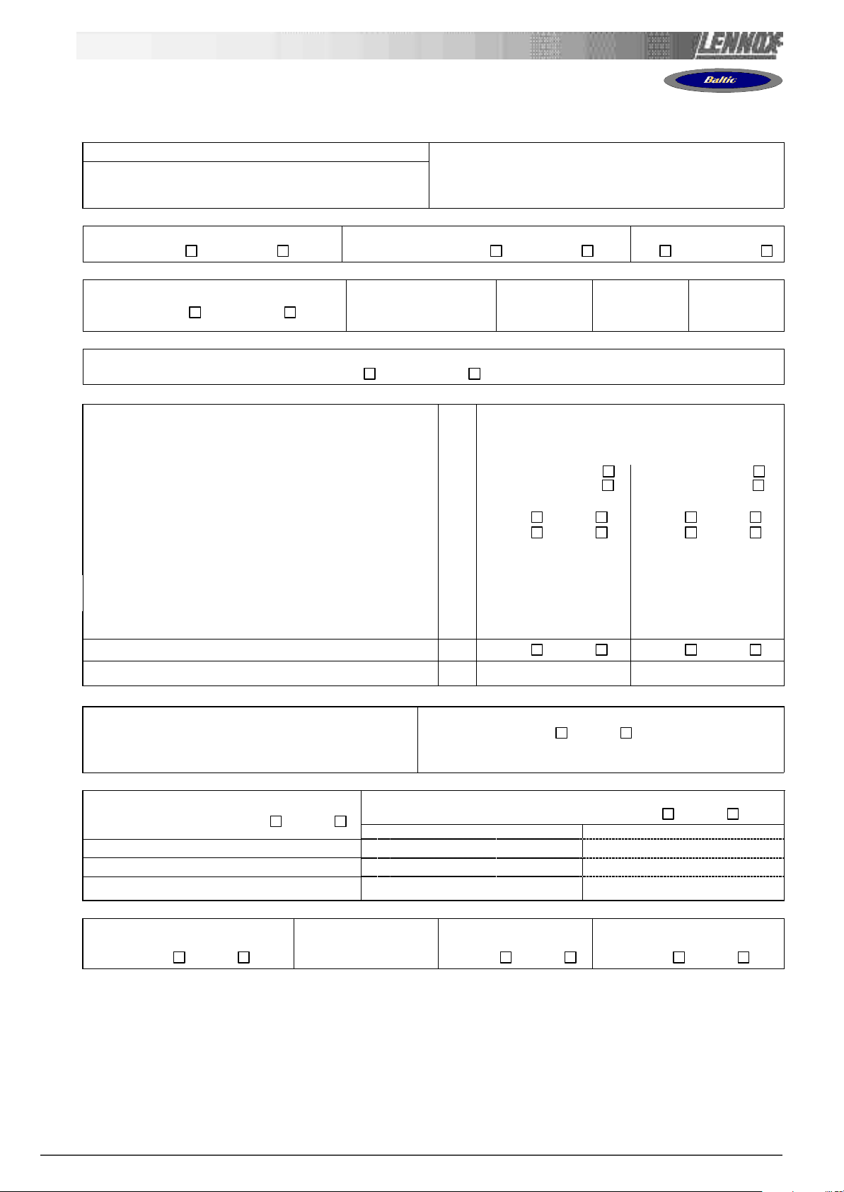
COMMISSIONING REPORT
Site details / Informations site
Site / Site
Unit Ref/ N° Affaire
Installer/ Installateur
………………………………………
……………………………………....
………………………………………
Controller/ Contrôleur
Model/Model
Serial No/ No Série
Refrigerant / Réfrigérant
………………………………….
……………….…………………
…………………………………
…………………………………
(1) ROOF INSTALLATION / INSTALLATION SUR LE TOIT
Sufficient Access OK / Accès Suffisants
Yes/Oui No/ Non
Condensate drain fitted / Drainage condensats
Installé Yes/Oui No/ Non
Roofcurb / Costière
OK Not OK/PasOK
(2) CONNECTIONS CHECK / VERIFICATIONS DE RACCORDEMENTS
Phase check/ Vérification des Phases
Yes / Oui No / Non
Voltage between Phases
Tension entre Phases
1 / 2
……………….
2 / 3
……………….
1 / 3
……………….
(3)CLIMATIC CONFIGURATION CHECK / VERIFIER LA CONFIGURATION CLIMATIC
CLIMATIC 50 Configured according to the Options and Specifications / CLIMATIC 50 configuré en fonction des options et des
spécifications: Yes/Oui No/ Non
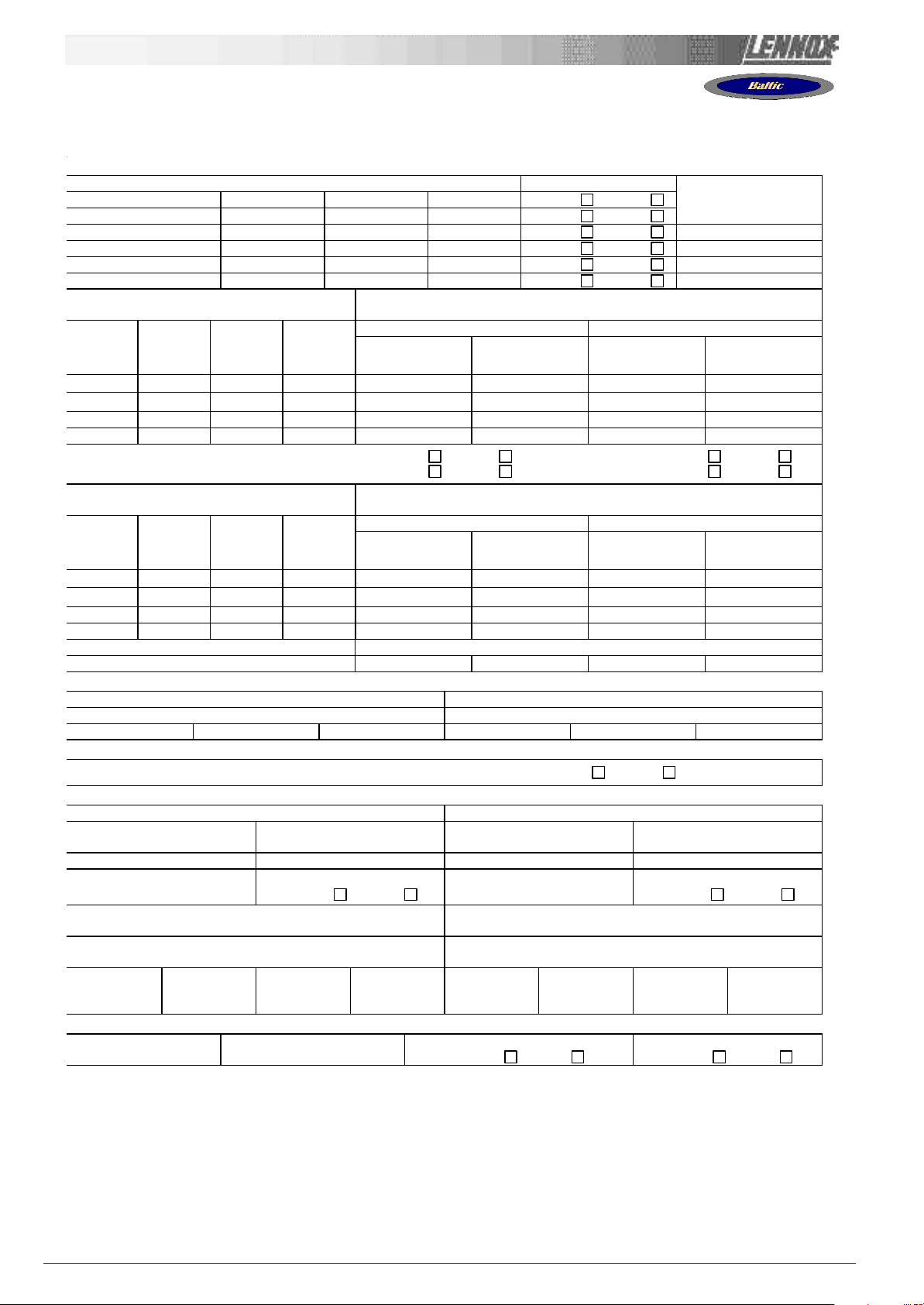
(4) SUPPLY BLOWER SECTION / VENTILATION TRAITEMENT
Type / Type:
Power displayed on plate / Puissance affichée sur la plaque:
Voltage displayed on plate / Tension affichée sur la plaque:
Current displayed on plate / Intensité affichée sur la plaque:
Fan Type / Type de Ventilateur: Forward / Action
Displayed Belt Length / Longueur Courroie affichée:
Tension Checked/ Tension Vérifiée: Yes/Oui No/ Non Yes/Oui No/ Non
Alignment Checked / Alignement Vérifié: Yes/Oui No/ Non Yes/Oui No/ Non
Motor Pulley Dia/ Poulie Moteur Dia: DM mm …………………… ……………………
Fan Pulley Dia/ Poulie Ventilateur Dia: DP mm …………………… ……………………
Fan Speed / Vitesse rotation Ventilateur = Motor rpm x DM / DP
Averaged Measured Amps / Intensité Mesurée moyenne:
Shaft Mechanical Power (Refer to airflow balancing)
Puissance Mécanique à l’Arbre (Voir section réglage débit)
Operating point checked / Vérif. Point de fonctionnement: Yes/Oui No/ Non Yes/Oui No/ Non
Estimated Airflow / Estimation Débit d’Air
KW
V
A
Backward / Réaction
mm …………………… ……………………
rpm
A
W …………………… ……………………
m3/h
N°1
……………………
……………………
……………………
Forward / Action
Backward / Réaction
……………………
……………………
…………………… ……………………
N°2
……………………
……………………
……………………
……………………
……………………
(5) AIRFLOW PRESS. SENSOR CHECK / VERIF. DES SECURITES PRESSOSTATS D’AIR
Measured pressure drop / Pertes de charge au pressostat
…………………………… mbar
Set Points Adjusted / Changement des consignes:
Yes/Oui No/ Non
If Yes enter new values/ Si oui noter les nouvelles consignes:
3410: ………… 3411: ………… 3412: …………
(6) EXTERNAL SENSOR CHECKS / VERIFICATION DES CAPTEURS EXTERNES
Check electrical connections / Vérification des
connections électriques: Yes/Oui No/ Non
Supply Temperature / Température Soufflage ………………………..°C ………………………..°C
Return Temperature / Température reprise ………………………..°C ………………………..°C
Outdoor Temperature / Température extérieure ………………………..°C ………………………..°C
Check and record temp. in menu 2110 / Vérifier et mesurer les
températures. Dans menu 2110: Yes/Oui No/ Non
100% Fresh Air / 100% Air neuf 100% return Air / 100% Air repris
(7) MIXING AIR DAMPERS CHECKS / VERIFICATIONS VOLETS DE MELANGE
Dampers open & close freely/
Volets s’ouvrent et se ferment OK
Yes/Oui No/ Non ……………..% Yes/Oui No/ Non Yes/Oui No/ Non
% Minimum FA:
%minimum Air Neuf:
Power exhaust checked/
Ventilateur extraction
Enthalpy sensor(s) checked/
Control enthalpie installé
IOM / ROOFTOP BALTIC Series - 0704-E Page 5
Page 7
COMMISSIONING REPORT
(8) REFRIGERATI
ON SECTION /
SECTION REFRIGERATION
Outdoor Fan Motor Current / Intensité Moteurs Batterie externe: Check Rotation
Motor 1 / Moteur 1 L1 ……..A L2 ……..A L3 ……A Yes/Oui No/ Non
Motor 2 / Moteur 2 L1 ……..A L2 ……..A L3 ……A Yes/Oui No/ Non
Motor 3 / Moteur 3 L1 ……..A L2 ……..A L3 ……A Yes/Oui No/ Non Comp1: …….. V
Motor 4 / Moteur 4 L1 ……..A L2 ……..A L3 ……A Yes/Oui No/ Non Comp2: …….. V
Motor 5 / Moteur 5 L1 ……..A L2 ……..A L3 ……A Yes/Oui No/ Non Comp3: …….. V
Motor 6 / Moteur 6 L1 ……..A L2 ……..A L3 ……A Yes/Oui No/ Non Comp4: …….. V
Compressor Amps COOLING / Intensité
Compresseur MODE FROID
Comp 1 …..… A …..… A …..… A ……… °C ……… °C ……… Bar ……… Bar
Comp 2 …..… A …..… A …..… A ……… °C ……… °C ……… Bar ……… Bar
Comp 3 …..… A …..… A …..… A ……… °C ……… °C ……… Bar ……… Bar
Comp 4 …..… A …..… A …..… A ……… °C ……… °C ……… Bar ……… Bar
Check Reversing valves./
Vérifier vannes d’inversion:
Compressor Amps HEATING / Intensité
Compresseur en Pompe à Chaleur
Comp 1 …..… A …..… A …..… A ……… °C ……… °C ……… Bar ……… Bar
Comp 2 …..… A …..… A …..… A ……… °C ……… °C ……… Bar ……… Bar
Comp 3 …..… A …..… A …..… A ……… °C ……… °C ……… Bar ……… Bar
Comp 4 …..… A …..… A …..… A ……… °C ……… °C ……… Bar ……… Bar
HP cut out / Coupure HP ……Bar LP cut out / Coupure sécurité BP ………..…... Bar
Refrigerant charge / Charge réfrigérant C1 : ………..kg C2 : ………..kg C3 : ………..kg C4 : ………..kg
Phase 1 Phase 2 Phase 3
Suction/ Asp
Valve1/Vanne1: Yes/Oui No/ Non
Valve2/Vanne2: Yes/Oui No/ Non
Phase 1 Phase 2 Phase 3
Suction/ Asp
Pressures & Temperatures / Pressions & températures
Temperatures / Temperatures Pressures / Pressions
Disch / refoul
Valve3/Vanne3: Yes/Oui No/ Non
Valve4/Vanne4: Yes/Oui No/ Non
Pressures & Temperatures / Pressions & températures
Temperatures / Temperatures Pressures / Pressions
Disch / refoul
LP/ BP
LP/ BP
(8)ELECTRIC HEATER SECTION / SECTION RECHAUFFEUR ELECTRIQUE
Type / Type: …………………………………………………. Serial No/ No Série.:………………………..
AMPS 1st stage (Baltic) / Intensité 1er étage (Baltic) AMPS 2nd stage (Baltic) / Intensité 2e étage (Baltic)
1 ………………. 2 ………………. 3 ………………. 1 ………………. 2 ………………. 3 ……………….
(9) HOT WATER COIL SECTION / SECTION BATTERIE EAU CHAUDE
Check Three Way Valve Movement / Vérification Mouvement Vanne trois voies: Yes/Oui No/ Non
(10) GAS HEATING SECTION / RAMPE GAZ
Gas Burner N°1 / Brûleur gaz N°1 Gas Burner N°2 / Brûleur gaz N°2
Size / Taille:
……………………….
Pipe size/ tuyauterie:
Line press./ press. ligne :
………………………
Check manifold pressure/ Pression injection:
High fire/Grande allure…….…Low fire/Petite allure………..
Pressure cut out airflow press switch / Pression coupure
pressostat débit d’air : ……………………mbar /Pa
Motor amps
I moteur:
……….A
Flue temp /
temp fumées
……… °C
Valve type / Type vanne:
…………………….
Gas type / Type gas : G…….
Drop test / test pression
Yes/Oui No/ Non
CO2 %:
………%
CO ppm:
………%
Size / Taille:
……………………….
Pipe size/ tuyauterie
line press./ press. ligne :
………………………
High fire/Grande allure…….…... Low fire/Petite allure………..
Motor Amps
Check manifold pressure/ Pression injection:
Pressure cut out airflow press switch / Pression coupure
pressostat débit d’air : ……………………mbar /Pa
I Moteur:
……….A
Flue temp /
temp fumées
………. °C
Valve type / Type vanne:
Gas type / Type gas : G…….
Drop test / test pression
Yes/Oui No/ Non
CO2 %:
………%
(11) REMOTE CONTROL BMS CHECK / VERIFICATIONS BMS CONTROL A DISTANCE
Type / Type:
…………………………..
Sensor type / Type Capteur
………………………………..
KP07 KP/17 checked/ vérifiées:
Yes/Oui No/ Non
Interconnect wiring checked:
Yes/Oui No/ Non
Compressor
Voltage/ Tension
Compresseur.
HP / HP
HP / HP
…………………….
CO ppm:
………%
Page 6 - IOM / ROOFTOP BALTIC Series - 0704 - E
Page 8
COMMISSIONING REPORT
dessous avant de transférer les consignes de zones vers le contrôleur
It is recommended that you fill the two tables below before transferring the zone settings to the Climatic controller.
Il est recommandé de remplir les deux tableaux ciClimatic50.
Refer to control section page 55 / Se référer à la section régulation page 55
Time Zones / Zones Horaires
Hour
Example
Monday
Tuesday
Wednesday
Thursday
Friday
Saturday
Sunday
0 1 2 3 4 5 6 7 8 9 10 11 12 13 14 15 16 17 18 19 20 21 22 23
UNO
7h15
ZA
11h00
ZB
14h00
ZC
19h00
UNO
Variables to adjust for each time zone / Consignes à renseigner pour chaque zone horaire
Monday
Tuesday
Wednesday
Thursday
Friday
Saturday
Sunday
Start z.A Start z.B Start z.C Start UNO
hour (3211) min (3212) hour (3213) min (3214) hour (3215) min (3216) hour (3217) min (3218)
Description Unit Menu Min
Sp Room °C 3311 8 35
Mini.Air % 3312 0 100
Sp Dyna °C 3321 0 99.9
Sp Cool °C 3322 8 35
Sp Heat °C 3323 8 35
Swap Heater On/Off 3324 ~ ~
Activation On/Off 3331 ~ ~
Swap Heater On/Off 3332 ~ ~
Sp.Dehu % 3341 0 100
Sp.Humi % 3342 0 100
Fan On/Off On/Off 3351 ~ ~
Fan Dead On/Off 3352 ~ ~
F.Air On/Off 3353 ~ ~
CO2 On/Off 3354 ~ ~
Comp.Cool. On/Off 3355 ~ ~
Comp.Heat. On/Off 3356 ~ ~
AuxHeat On/Off 3357 ~ ~
Humidif. On/Off 3358 ~ ~
Low Noise On/Off 3359 ~ ~ N/A N/A N/A
Max
Zone A Zone B Zone C UNOC
IOM / ROOFTOP BALTIC Series - 0704-E Page 7
Page 9

COMMISSIONING REPORT
COMMENTS.............................................................................................................................................................................
.................................................................................................................................................................................................
.................................................................................................................................................................................................
.................................................................................................................................................................................................
.................................................................................................................................................................................................
.................................................................................................................................................................................................
.................................................................................................................................................................................................
.................................................................................................................................................................................................
.................................................................................................................................................................................................
.................................................................................................................................................................................................
.................................................................................................................................................................................................
.................................................................................................................................................................................................
.................................................................................................................................................................................................
.................................................................................................................................................................................................
.................................................................................................................................................................................................
.................................................................................................................................................................................................
.................................................................................................................................................................................................
.................................................................................................................................................................................................
.................................................................................................................................................................................................
.................................................................................................................................................................................................
.................................................................................................................................................................................................
.................................................................................................................................................................................................
.................................................................................................................................................................................................
.................................................................................................................................................................................................
.................................................................................................................................................................................................
.................................................................................................................................................................................................
.................................................................................................................................................................................................
.................................................................................................................................................................................................
.................................................................................................................................................................................................
.................................................................................................................................................................................................
.................................................................................................................................................................................................
.................................................................................................................................................................................................
.................................................................................................................................................................................................
.................................................................................................................................................................................................
.................................................................................................................................................................................................
.................................................................................................................................................................................................
.................................................................................................................................................................................................
.................................................................................................................................................................................................
.................................................................................................................................................................................................
.................................................................................................................................................................................................
.................................................................................................................................................................................................
.................................................................................................................................................................................................
.................................................................................................................................................................................................
.................................................................................................................................................................................................
.................................................................................................................................................................................................
.................................................................................................................................................................................................
.................................................................................................................................................................................................
.................................................................................................................................................................................................
.................................................................................................................................................................................................
.................................................................................................................................................................................................
.................................................................................................................................................................................................
.................................................................................................................................................................................................
.................................................................................................................................................................................................
.................................................................................................................................................................................................
.................................................................................................................................................................................................
.................................................................................................................................................................................................
.................................................................................................................................................................................................
.................................................................................................................................................................................................
.................................................................................................................................................................................................
.................................................................................................................................................................................................
.................................................................................................................................................................................................
.................................................................................................................................................................................................
Page 8 - IOM / ROOFTOP BALTIC Series - 0704 - E
Page 10
TRANSPORT - HANDLING
DELIVERY CHECKS
On receipt of a new equipment please check the following
points. It is the customer's responsibility to ensure that the
products are in good working order:
- The exterior has not been damaged in any way.
- The lifting and handling equipment are suitable for the
equipment and comply with the specifications of the handling
instructions enclosed here-in.
- Accessories ordered for on site installation have been
delivered and are in good working order.
- The equipment supplied corresponds to the order and
matches the delivery note.
If the product is damaged, exact details must be confirmed
in writing by registered post to the shipping company within
48 hours of delivery (working days). A copy of the letter must
be addressed to Lennox and the supplier or distributor for
information purposes. Failure to comply will invalidate any
claim against the shipping company.
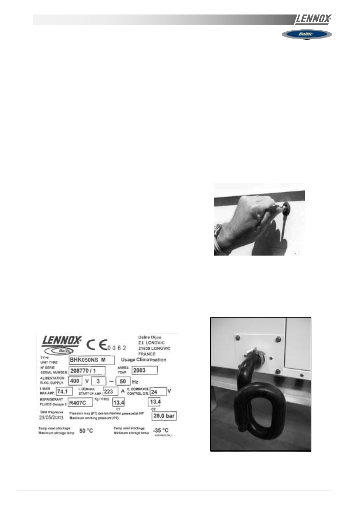
RATING PLATE
The rating plate provides a complete reference for the model
and ensures that the unit corresponds to the model ordered.
It states the electrical power consumption of the unit on startup, its rated power and its supply voltage. The supply voltage
must not deviate beyond +10/-15 %. The start-up power is
the maximum value likely to be achieved for the specified
operational voltage. The customer must have a suitable
electrical supply. It is therefore important to check whether
the supply voltage stated on the unit's rating plate is
compatible with that of the mains electrical supply. The rating
plate also states the year of manufacture as well as the type
of refrigerant used and the required charge for each
compressor circuit.
STORAGE
When units are delivered on site they are not always required
immediately and are sometimes put into storage. In the event
of medium to long-term storage, we recommend the following
procedures :
- Ensure that there is no water in the hydraulic systems.
- Keep the heat exchanger covers in position (AQUILUX cover).
- Keep protective plastic film in position.
- Ensure the electrical panels are closed.
- Keep all items and options supplied in a dry and clean
place for future assembly before using the equipment.
MAINTENANCE KEY
On delivery we recommend that you keep the key which is
attached to an eyebolt in a safe and accessible place. This
allows you to open the panels for maintenance and
installation work.
The locks are ¼ turn + then tighter (figure 1).
Fig. 1
CONDENSATE DRAINS
The condensate drains are not assembled when delivered
and are stored
in the electrical panel with their clamping collars.
To assemble them, insert them on the condensate tray outlets
and use a screwdriver to tighten the collars (Figure 2).
2
Fig. 2
IOM / ROOFTOP BALTIC Series - 0704-E Page 9
Page 11
A
B
D
C
A
B
D
C
A
B
D
C
TRANSPORT - HANDLING
B BOX
D BOX
C BOX
E BOX
C
B
A
D
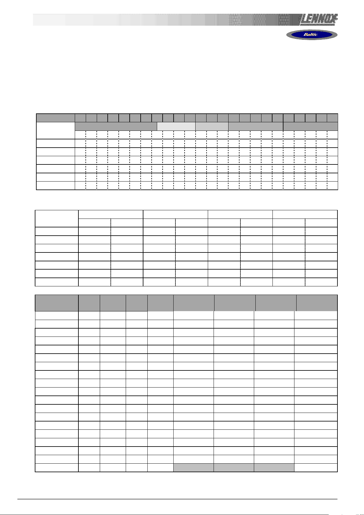
BALTIC BCK/BHK/BGK/BDK 020 025 030 035 040 045 050 060 070
View B BOX B BOX C BOX C BOX D BOX D BOX D BOX E BOX E BOX
A mm 2017 2017 1890 1890 1910 1910 1910 2260 2260
B mm 1418 1418 1915 1915 2235 2235 2235 2873 2873
C mm 1220 1220 1221 1221 1221 1221 1221 1225 1225
D mm 484 484 414 414 418 418 418 418 418
Weight of standard units (S:single/D:dual)
SS
S
SS
Without hood kg 394 414 541 528 547 529 589 591 604 604 619 796 852
With hood kg 417 437 569 556 575 556 622 624 677 677 652 83 7 893
Weight of gas units
Standard heat without hood kg 445 465 602 589 608 590 663 665 678 678 693 904 960
Standard heat with hood kg 468 488 630 617 636 618 696 698 711 711 726 945 1001
SS
S
SS
High heat without hood kg 454 474 621 608 627 609 685 687 700 700 715 963 1019
High heat with hood kg 4 7 7 497 649 636 655 637 661 720 733 733 748 1004 1060
SS
DD
SS
DD
SS
DD
SS
DD
SS
S
D
S
D
S
D
S
SS
DD
SS
DD
SS
DD
SS
DD
SS
DD
SS
S
D
S
SS
DD
D
SS
DD
DD
S
D
SS
DD
D
SS
DD
SS
DD
S
D
SS
DD
DD
S
D
SS
DD
SS
DD
S
D
SS
DD
DD
D
DD
DD
D
DD
DD
D
DD
DD
D
DD
Page 10 - IOM / ROOFTOP BALTIC Series - 0704 - E
Page 12
TRANSPORT - HANDLING
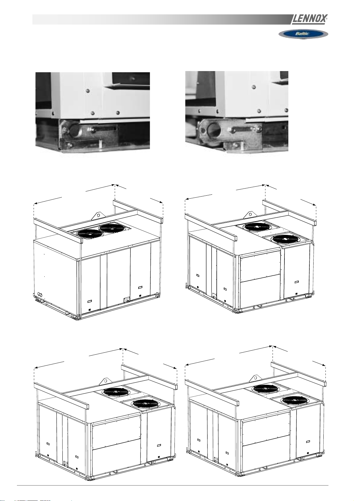
RETRACTABLE LIFTING LUG
LIFTING B BOX
1850 1410
(mini) (mini)
LIFTING D BOX
LIFTING C BOX
1930 1700
(mini) (mini)
LIFTING E BOX
2250
(mini)
1700
(mini)
2890
(mini) (mini)
IOM / ROOFTOP BALTIC Series - 0704-E Page 11
2080
Page 13
TRANSPORT - HANDLING
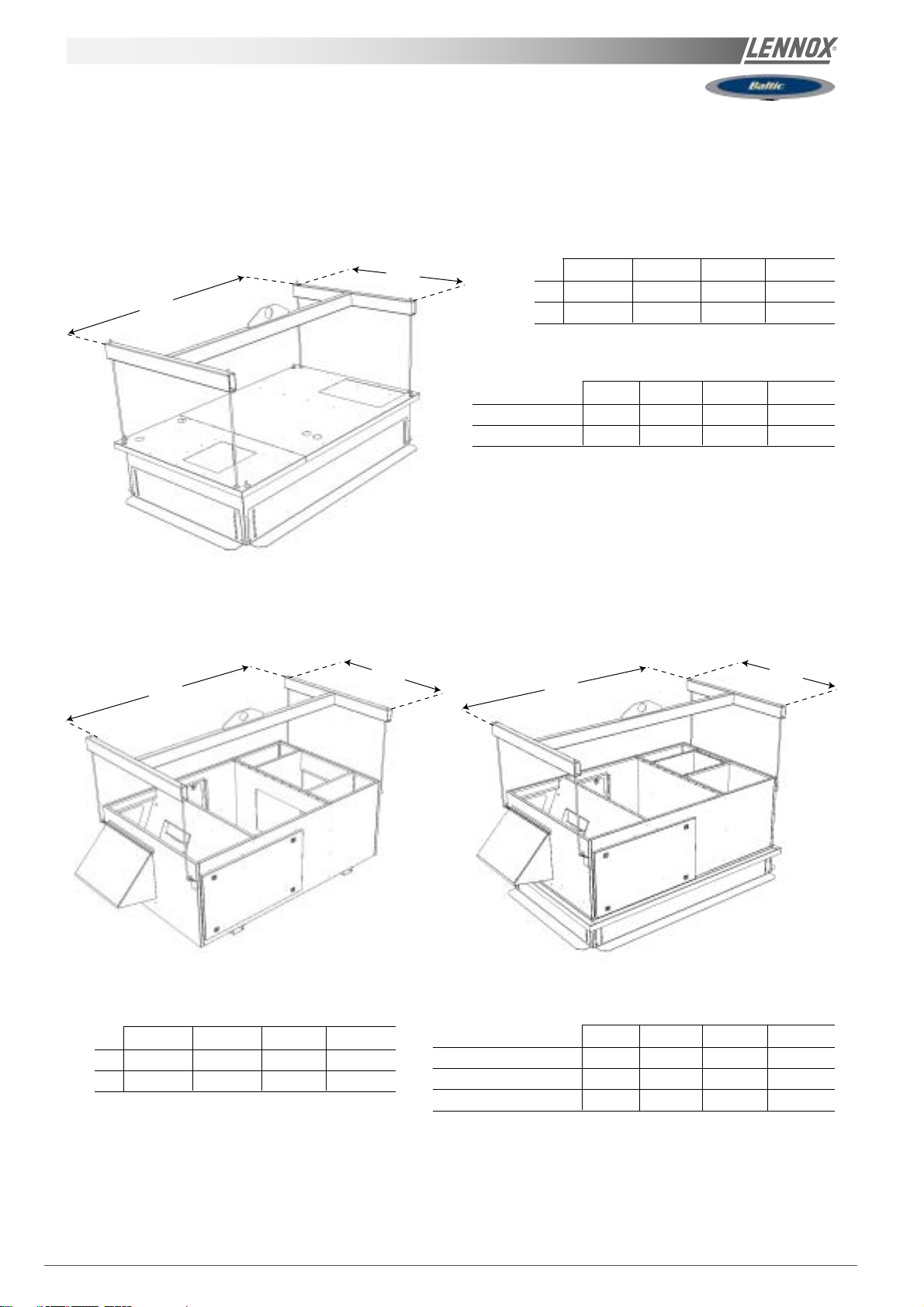
LIFTING THE ROOFCURBS
Adjustable Roofcurb
A
Exhaust Horizontal Roofcurb
A
B
B
Dimensions (mm)
B box C box D box E box
A 1890 1735 1735 2085
B 1100 1295 1545 1995
Weights (kg)
B box C box D box E box
No aux.heating 87 9 4 104 1 52
With aux.heating 86 90 100 138.2
Exhaust Vertical Roofcurb
A
B
Dimensions (mm)
B box C box D box E box
A 2050 1900 1900 2250
B 1160 1360 1610 2060
Page 12 - IOM / ROOFTOP BALTIC Series - 0704 - E
Weights (kg)
B box C box D box E box
Vertical No aux.heating 19 2 220 2 4 0 370
Vertical With aux.heating 194 194 240 365
Horizontal 142 168 185 301
Page 14
TRANSPORT - HANDLING
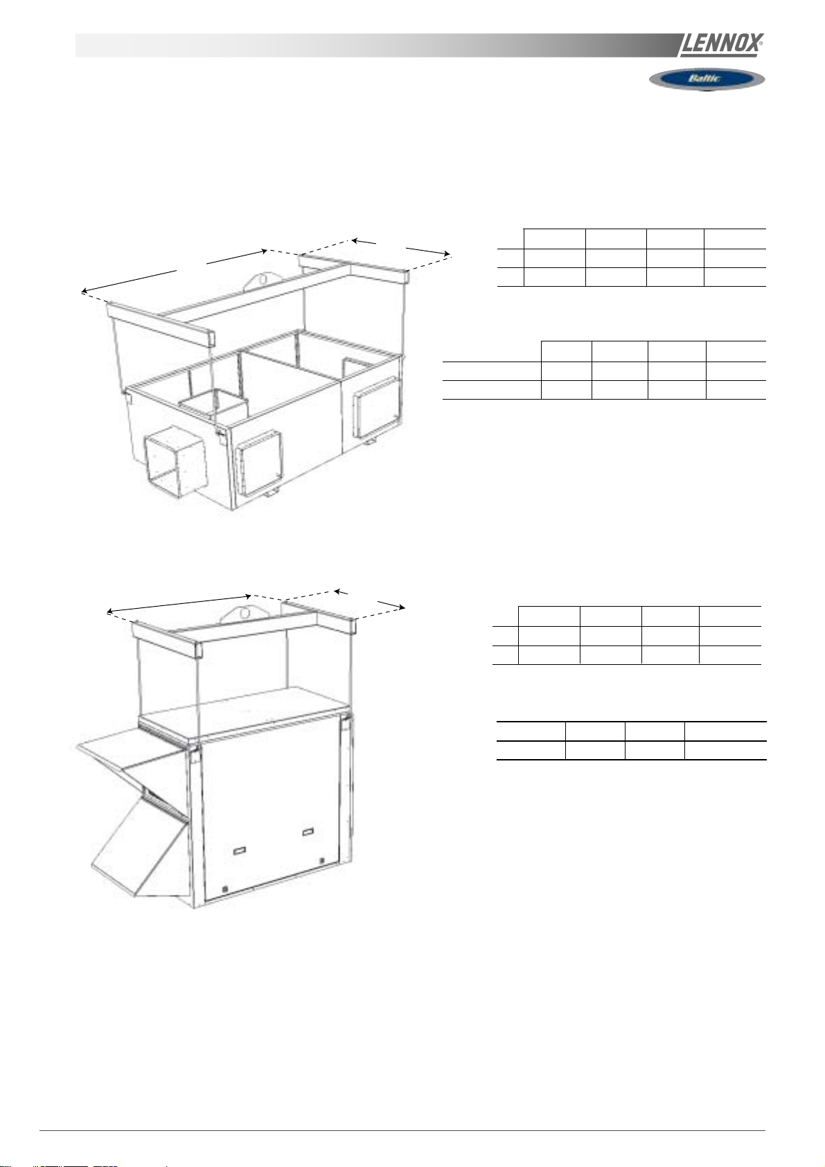
Multidirectional (mm)
A
Energy Recovery
A
B
B
Dimensions (mm)
B box C box D box E box
A 2050 1900 1900 2250
B 1160 1360 1610 2060
Weights (kg)
B box C box D box E box
No aux.heating 81 8 8 100 1 47
With aux.heating 90 93 10 3 146.7
Dimensions (mm)
B box C box D box E box
A 1290 1290 1290 1290
B 820 1170 1547 1895
Weights (kg)
B box C box D box E box
143 172 229 317
IOM / ROOFTOP BALTIC Series - 0704-E Page 13
Page 15
TRANSPORT - HANDLING
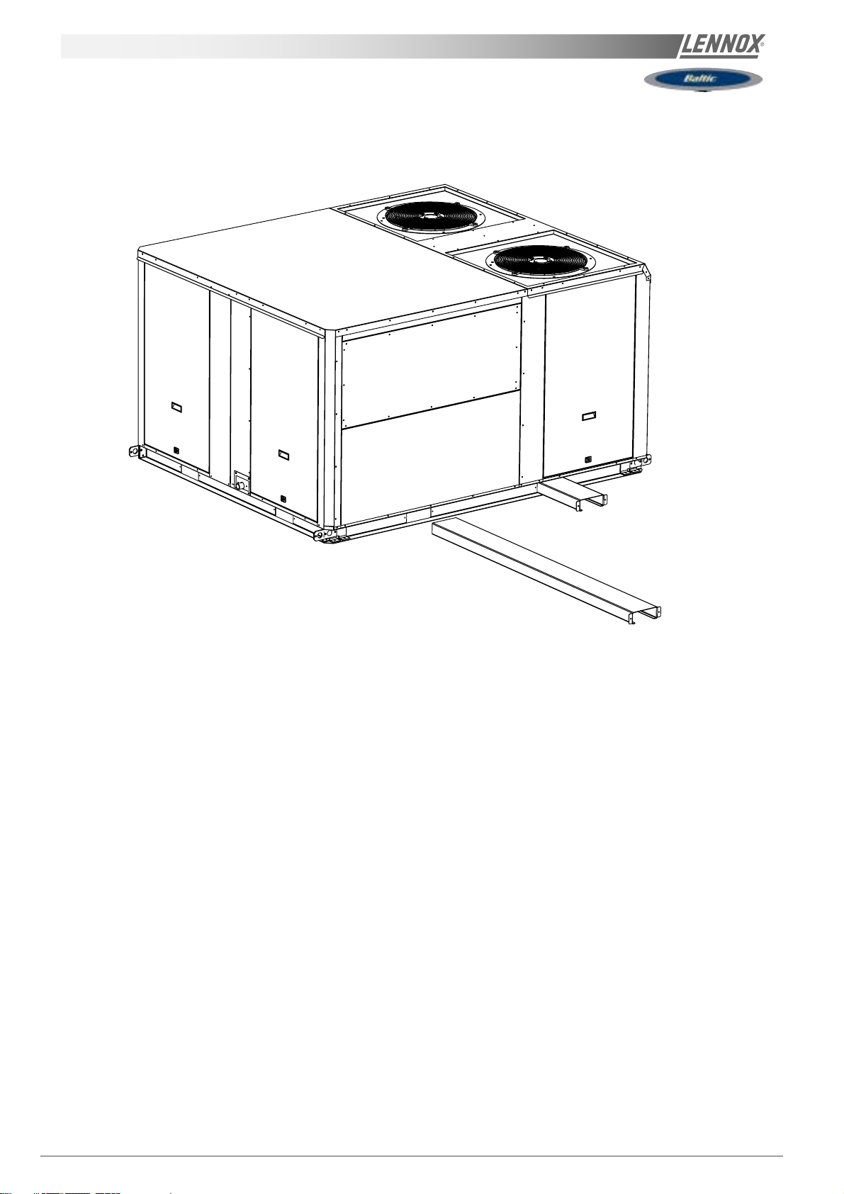
FORKLIFT PROTECTIONS
NEVER LIFT THE UNIT WITHOUT FORLIFT PROTECTIONS
REMOVE FORKLIFT PROTECTIONS
BEFORE INSTALLATION
PRELIMINARY CHECKS
Before installing the equipment, the following points MUST
be checked :
-Have the forklift protections been removed ?
-Is there sufficient space for the equipment?
-Is the surface on which the equipment is to be installed
sufficiently solid to withstand its weight? A detailed study of
the frame must be made beforehand.
-Do the supply and return ductwork openings excessively
weaken the structure?
-Are there any obstructing items which could hinder the
operation of the equipment?
-Does the electrical power available correspond to the
equipment's electrical specifications?
-Is drainage provided for the condensate?
-Is there sufficient access for maintenance?
-Installation of the equipment could require different lifting
methods which may vary with each installation (helicopter or
crane). Have these been evaluated ?
-Ensure that the unit is installed in accordance with the
installation instructions and local applicable codes.
-Check to ensure that the refrigerant lines do not rub against
the cabinet or against other refrigerant lines.
In general, make sure no obstacles (walls, trees or roof
ledges) are obstructing the duct connections or hindering
assembly and maintenance access.
INSTALLATION REQUIREMENTS
The surface on which the equipment is to be installed
must be clean and free of any obstacles which could
hinder the flow of air to the condensers:
-Avoid uneven surfaces
-Avoid installing two units side by side or close to each
other as this may restrict the airflow to the condensers.
Before installing a packaged Rooftop unit it is important to
understand :
-The direction of prevailing winds.
-The direction and position of air flows.
-The external dimensions of the unit and the dimensions
of the supply and return air connections.
-The arrangement of the doors and the space required to
open them to access the various components.
CONNECTIONS
-Ensure that all the pipe-work crossing walls or roofs are
secured, sealed and insulated.
-To avoid condensation problems, make sure that all pipes
are insulated according to the temperatures of fluids and
type of rooms.
NOTE: The AQUILUX protection sheets fitted to the finned
surfaces must be removed prior to start up.
Page 14 - IOM / ROOFTOP BALTIC Series - 0704 - E
Page 16
TRANSPORT - HANDLING
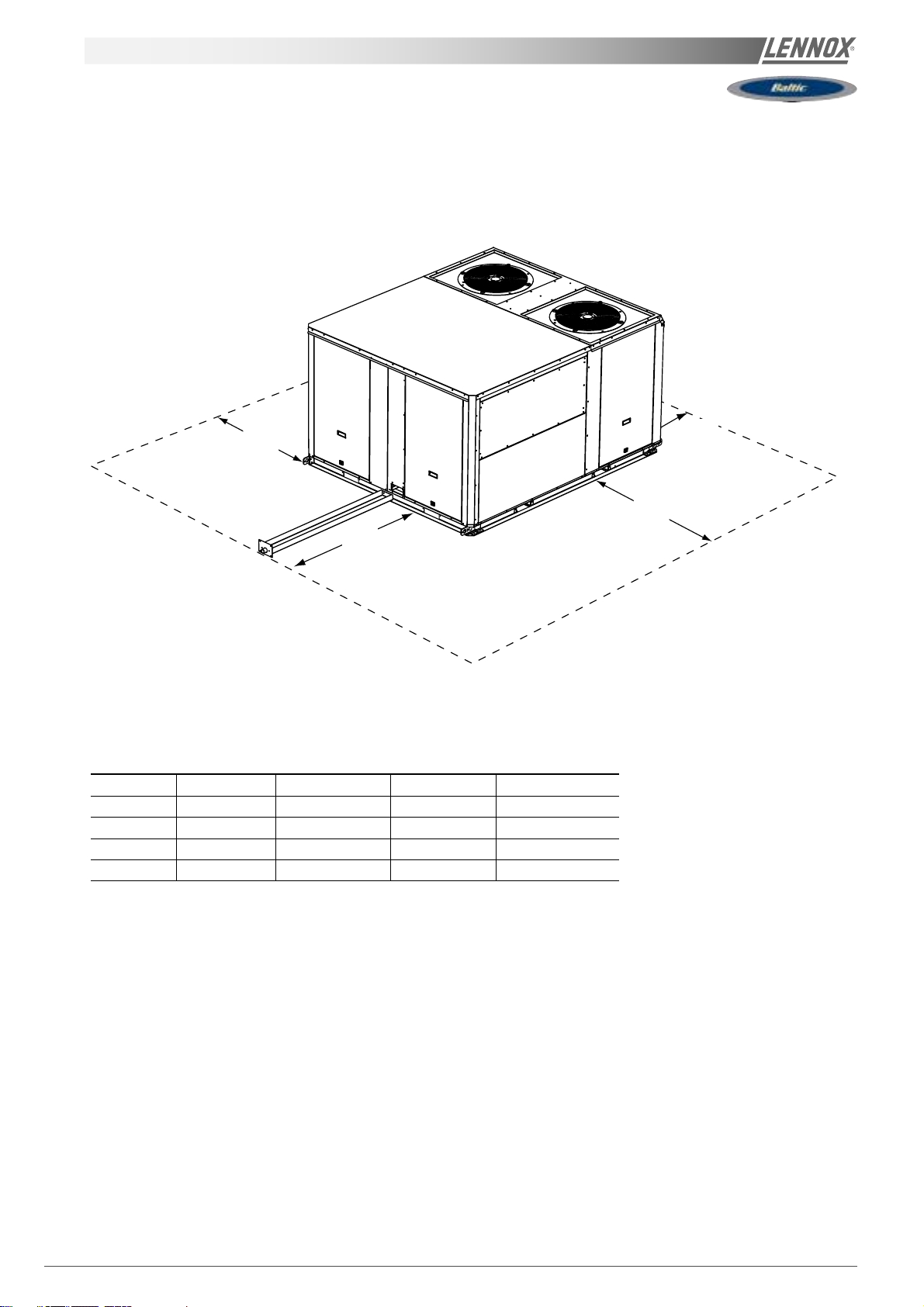
MINIMUM CLEARANCE AROUND THE UNIT
Figure 4 shows the required clearances and service access around the unit.
NOTE : Ensure the fresh air inlet does not face prevailing wind direction.
D
A
ABC D
B Box 1000 (1) 1500 (2) 1500 1000
C Box 1200 (1) 1500 (2) 1500 1000
D Box 1400 (1) 1500 (2) 1500 1000
E Box 1800 (1) 1500 (2) 1500 1100
C
B
(1) Add 1 meter if the units are equipped with gas burner
(2) Double this distance if the units are equipped with extraction
IOM / ROOFTOP BALTIC Series - 0704-E Page 15
Page 17
INSTALLATION ON A ROOF MOUNTING FRAMES
NON ADJUSTABLE NON ASSEMBLiED ROOFCURB INSTALLATION ..
INSTALLATION ON A ROOF MOUNTING FRAME .......................................
CURBING AND FLASHING .............................................................................
P29
P41
P41
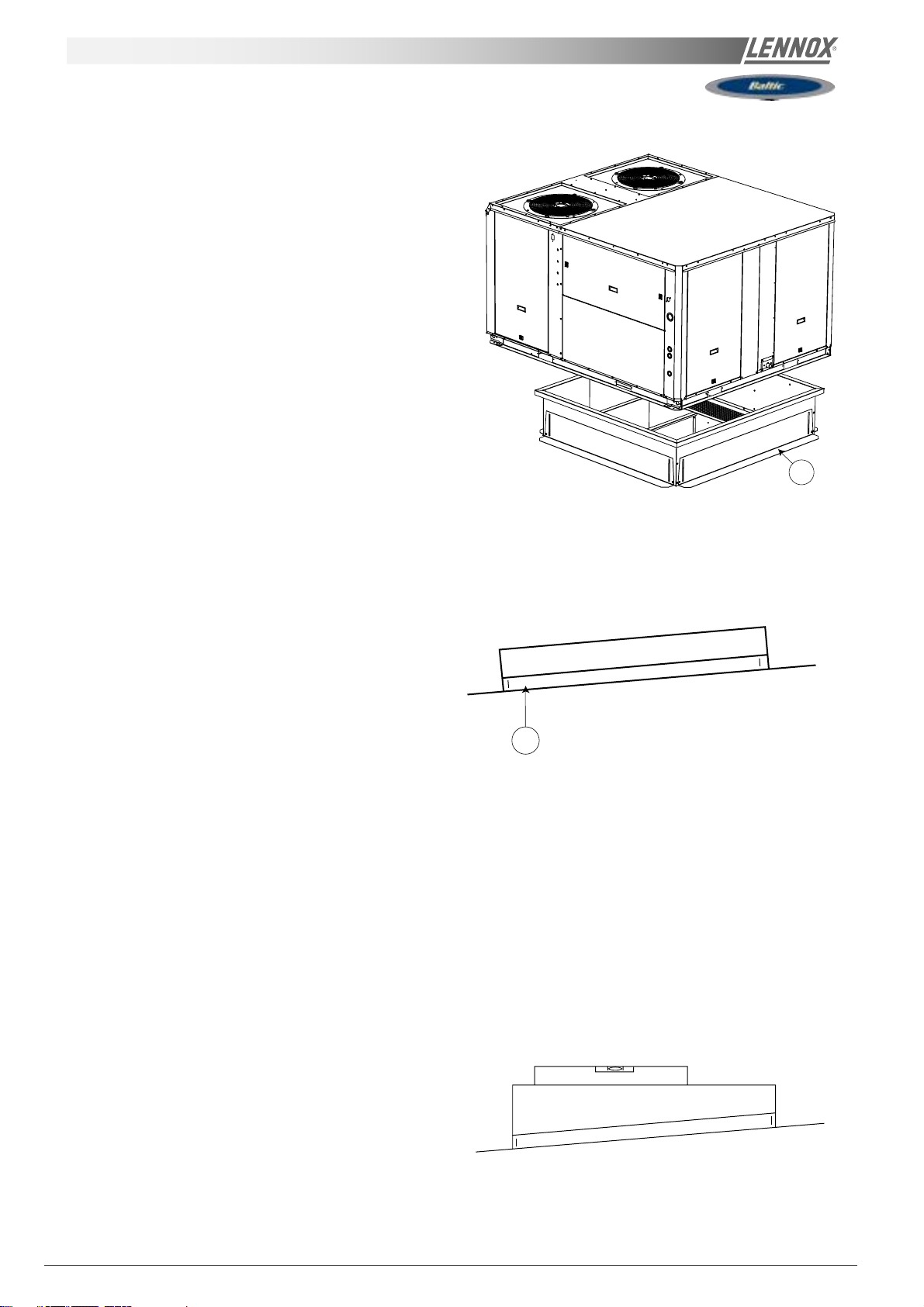
As levels are adjustable, observe the following
recommendations when installing the equipment.
Above all, ensure that all the adjustable returns are facing
outward 1 ( figure 3). They are usually turned inside-out for
transport.
1
Fig. 3
Place the roof mounting frame on the trimmer beam by first
lining up the inlet and the outlet opening. ("2"- figure 4)
After levelling the frame, secure the adjustable returns on
the trimmer (figure 5).
2
Fig. 4
Fig. 5
It is important to centre the unit on the roof frame.
Page 16 - IOM / ROOFTOP BALTIC Series - 0704 - E
Page 18
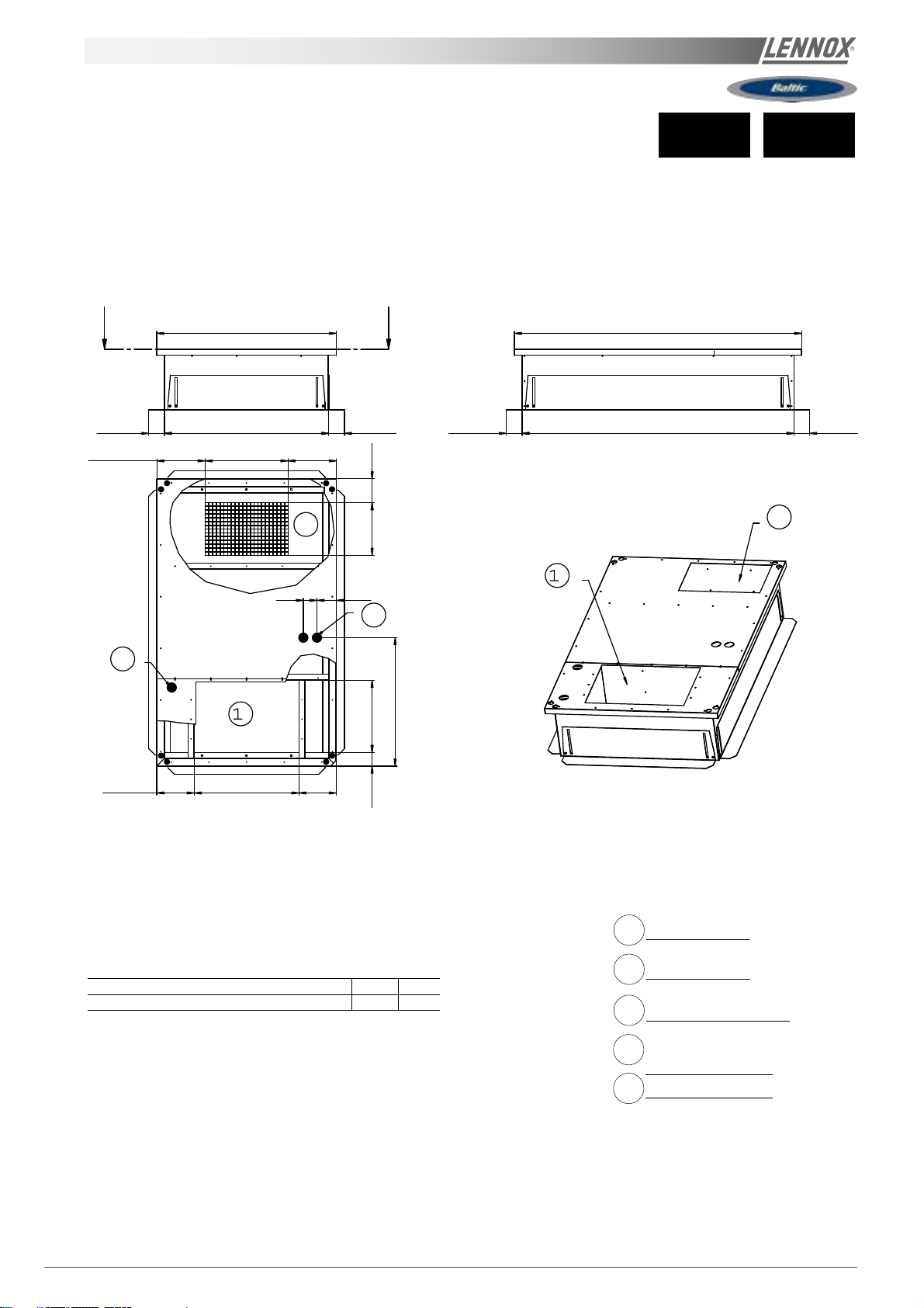
adjustable ROOFCURB DRAWINGS
020 025
15834747690.5
AA
1896
1186
103.5 1085 103.5 103.5 1795 103.5
319.2 547 319.5
Roof opening 1795 x 1085
2D
D
12890
5
D
A-A
8
D
848
2D
247.5
A
BCK / BHK without auxiliary heating 543 39 5
BGK / BDK or BCK / BHK with auxiliary heating 2 47 6 91
B
AB
Down Supply Air
1D
DownReturn Air
2D
Down main power entry
4D
Down hot water
5D
Entry
Main Power Entry
8
IOM / ROOFTOP BALTIC Series - 0704-E Page 17
Page 19
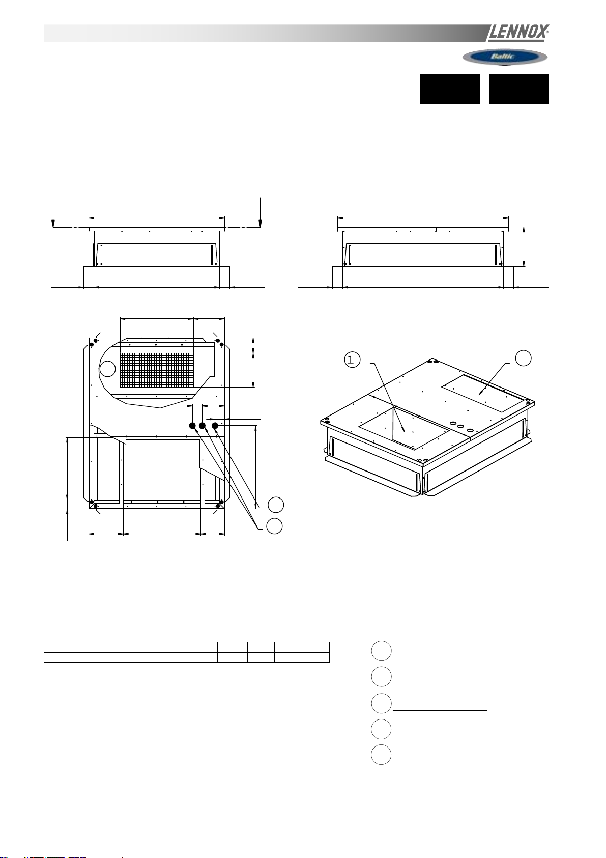
adjustable ROOFCURB DRAWINGS
A
030 035
1383 1743
103.5 1282 103.5
747 318
158347
2D
227.5100
A-A
97.5
A
A
847.5
Roof opening 1642 x 1282
D
401
103.51642103.5
2D
8
90.5
BCK / BHK without auxiliary heating 49 6 6 33 4 00 3 49
BGK / BDK or BCK / BHK with auxiliary heating 6 36 3 51 7 90 2 41
BCD
ABCD
5
D
Down Supply Air
1D
DownReturn Air
2D
Down main power entry
4D
Down hot water
5D
Entry
Main Power Entry
8
Page 18 - IOM / ROOFTOP BALTIC Series - 0704 - E
Page 20
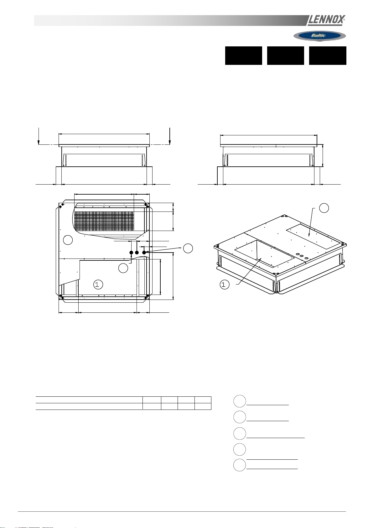
adjustable ROOFCURB DRAWINGS
045 050040
1633
103.51532103.5
1072 280.5
157347847.5
2D
227100
97
5D
D
ABC
1743
401
103.5 1642 103.5
Roof opening 1642 x 1532
2D
8
DD
ABCD
BCK / BHK without auxiliary heating 63 7 3 52 1050 230
BGK / BDK or BCK / BHK with auxiliary heating 4 96 7 50 5 00 3 82
Down Supply Air
1D
DownReturn Air
2D
Down main power entry
4D
Down hot water
5D
Entry
Main Power Entry
8
IOM / ROOFTOP BALTIC Series - 0704-E Page 19
Page 21
adjustable ROOFCURB DRAWINGS
2082
2D
BCK
BhK
(*) without auxiliary electric heater
without hot water coil.
292.51497292.5
5
D
347 199
060 070
2092
401
103.51992103.5103.51982103.5
2D
97
D
D
380287380 431.5
410466
1197
Down Supply Air
1D
DownReturn Air
2D
8
Page 20 - IOM / ROOFTOP BALTIC Series - 0704 - E
Down main power entry
4D
Down hot water
5D
Entry
Main Power Entry
8
Page 22
adjustable ROOFCURB DRAWINGS
2082
2D
BGK
BDK
(*) This roofcurb is also necessary for all cooling
only or heatpump rooftop with auxiliary electric
heater or hot water coil.
292.51497292.5
5
D
347 199
060 070
2092
401
103.51992103.5103.51982103.5
2D
97
D
D
380287380 431.5
410466
1197
Down Supply Air
1D
DownReturn Air
2D
8
Down main power entry
4D
Down hot water
5D
Entry
Main Power Entry
8
IOM / ROOFTOP BALTIC Series - 0704-E Page 21
Page 23
MULTIDIRECTIONAL HORIZONTAL ROOFCURB
2F'
2F
BCK
BHK
(*) without auxiliary electric heater
without hot water coil.
2F'
020 025
1F1F
1F'
2F
1F'
Front supply air
1F
Front supply air
1F'
Front return air
2F
Front return air
2F'
1F
2F'
2F
2F'
1F'
1F
WARNING : ONL Y ONE OF THE 4 FOLLOWINGS POSSIBILITIES :
2F - 1F / 2F - 1F'
2F' - 1F / 2F' - 1F'
Page 22 - IOM / ROOFTOP BALTIC Series - 0704 - E
Page 24
MULTIDIRECTIONAL HORIZONTAL ROOFCURB
2F'
1F'
2F
1F
BGK
BDK
(*) This roofcurb is also necessary for all cooling
only or heatpump rooftop with auxiliary electric
heater or hot water coil.
2F'
020 025
1F
1F'
2F
1F
Front supply air
1F
Front supply air
1F'
Front return air
2F
2F'
2F
1F'
1F
WARNING : ONL Y ONE OF THE 4 FOLLOWINGS POSSIBILITIES :
2F - 1F / 2F - 1F'
2F' - 1F / 2F' - 1F'
2F'
Front return air
2F'
IOM / ROOFTOP BALTIC Series - 0704-E Page 23
Page 25
MUL TIDIRECTIONAL HORIZONTAL ROOFCURB
2F'
2F
1F
BCK
BHK
(*) without auxiliary electric heater
without hot water coil.
1F' 1F 1F'
035030
2F
1F'
1F
Front supply air
1F
Front supply air
1F'
Front return air
2F
2F'
2F
2F'
1F'
WARNING : ONL Y ONE OF THE 4 FOLLOWINGS POSSIBILITIES :
2F - 1F / 2F - 1F'
2F' - 1F / 2F' - 1F'
1F
Front return air
2F'
Page 24 - IOM / ROOFTOP BALTIC Series - 0704 - E
Page 26
MULTIDIRECTIONAL HORIZONTAL ROOFCURB
BGK
BDK
(*) This roofcurb is also necessary for all cooling
only or heatpump rooftop with auxiliary electric
heater or hot water coil.
2F' 2F 1F 2F'
030 035
1F
1F'
2F
1F'
Front supply air
1F
Front supply air
1F'
1F 2F'
2F
2F'
1F'
WARNING : ONL Y ONE OF THE 4 FOLLOWINGS POSSIBILITIES :
2F - 1F / 2F - 1F'
2F' - 1F / 2F' - 1F'
1F
Front return air
2F
Front return air
2F'
IOM / ROOFTOP BALTIC Series - 0704-E Page 25
Page 27
MULTIDIRECTIONAL HORIZONTAL ROOFCURB
2F'
1F'
2F
2F
1F
BGK
BDK
(*) This roofcurb is also necessary for all cooling only or heatpump
rooftop with auxiliary electric heater or hot water coil.
2F'
1F'
045 050040
1F
1F'
2F
2F'
Front supply air
1F
Front supply air
1F'
Front return air
2F
Front return air
2F'
1F
2F'1F
WARNING : ONL Y ONE OF THE 4 FOLLOWINGS POSSIBILITIES :
2F - 1F / 2F - 1F'
2F' - 1F / 2F' - 1F'
Page 26 - IOM / ROOFTOP BALTIC Series - 0704 - E
Page 28
MULTIDIRECTIONAL HORIZONTAL ROOFCURB
BCK
BHK
2080
2F
340 1400 340 130 700 900 90
1F'
750
1F
2F
2090 2080
2F'
BGK
BDK
71040
060 070
1F'
465 1400 215
2F
500
100
1F
1F
1F'
2F
2F'
Front supply air
Front supply air
Front return air
1F'
2F'
1F
WARNING : ONL Y ONE OF THE 4 FOLLOWINGS POSSIBILITIES :
2F - 1F / 2F - 1F'
2F' - 1F / 2F' - 1F'
Front return air
2F'
IOM / ROOFTOP BALTIC Series - 0704-E Page 27
Page 29

INST ALLATION ON A ROOF MOUNTING FRAME
NON ADJUSTABLE NON ASSEMBLIED ROOFCURB INSTALLATION
FRAME PAR TS IDENTIFICA TION
Figure 6 shows the different parts for identification
INSTALLATION
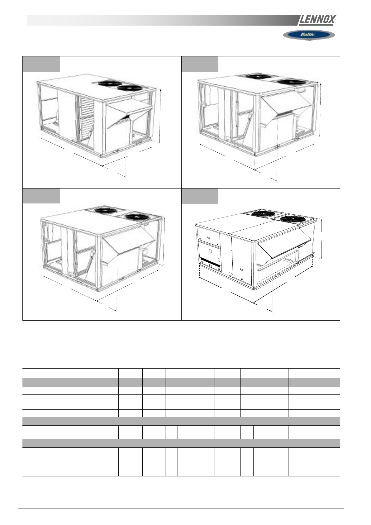
The roof mounting frame provides support when the units are installed in down-flow configurations.
The non adjustable, non assembled roof mounting frame can be installed directly on decks having adequate structural
strength or on roof supports under deck. See page 29 for frame dimensions, location of supply and return air opening
NOTE: frame assembly must be installed flat, levelled within 5mm per linear meter in any direction.
UNIT FLOOR
INSULA TION
AIR DUCT
Fig. 6
UNIT FLOOR
UNIT SUPPORT RAIL
ROOFCURB
Page 28 - IOM / ROOFTOP BALTIC Series - 0704 - E
Page 30
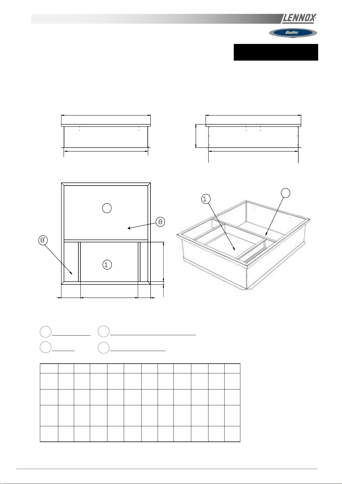
Non-adjustable ROOFCURB
BCK = Cooling only unit
BHK = Heat pump unit
BGK = Cooling only unit with gas fired heating
BDK = Heat pump unit with gas fired heating
A
J I
2D
All units
B
D
Roof opening I x J
2D
D
D
G
H
E
Down Supply Air
1D
Return Air
2D
Type Taille A B C D E F G H I J
All 020
All 030
All 040
All 060
1183 1893 691 400 246 246 515 50 1783 1083
025
1380 1740 790 400 351 240 675 50 1640 1280
035
045 1630 1740 1050 400 352 229 675 50 1640 1530
050
2080 2090 1400 400 425 255 720 156 1990 1980
070
CF
Main Power Entry 030-035-040-045-050
8
Main Power Entry 020-025
8'
(*) Non adjustable, non assembled roofcurb.
IOM / ROOFTOP BALTIC Series - 0704-E Page 29
Page 31

exhaust vertical ROOFCURB
2286
020 025
1942
103.5 1893 103.5
89 476
344
B
A
1283
246
900
9
103.5 1183 103.5
8
347 156
318547318
2D1D
90127
5D
847
AB
BCK / BHK without auxiliary heating 39 5 5 42
BGK / BDK or BCK / BHK with auxiliary heating 6 91 24 6
Page 30 - IOM / ROOFTOP BALTIC Series - 0704 - E
Down Supply Air
1D
DownReturn Air
2D
Down main power entry
4D
Down hot water
5D
Entry
Main Power Entry
8
Exhaust
9
Page 32

exhaust vertical ROOFCURB
2133
3441789
900
030 035
9
103.5 1740 103.5
A
B
1480
C
89 636
103.5 1380 103.5
5
D
347 156
2D
D
100
225
846
95
8
747316.5 316.5
ABC
BCK / BHK without auxiliary heating 632 40 0 34 8
BGK / BDK or BCK / BHK with auxiliary heating 3 50 7 90 24 0
Down Supply Air
1D
DownReturn Air
2D
Down main power entry
4D
Down hot water
5D
Entry
Main Power Entry
8
Exhaust
9
IOM / ROOFTOP BALTIC Series - 0704-E Page 31
Page 33

exhaust vertical ROOFCURB
2133
344
9
045 050040
900
1840
103.51740103.5
347 156
103.51630103.5
A
DD
2D
B
1730
100224
C
89
8
95
846
5D
279 1072 279
D
ABCD
BCK / BHK without auxiliary heating 74 9 5 00 3 82 4 96
BGK / BDK or BCK / BHK with auxiliary heating 3 51 1050 229 636
Page 32 - IOM / ROOFTOP BALTIC Series - 0704 - E
Down Supply Air
1D
DownReturn Air
2D
Down main power entry
4D
Down hot water
5D
Entry
Main Power Entry
8
Exhaust
9
Page 34

exhaust vertical ROOFCURB
603430
2190
2482
BCK
BHK
(*) without auxiliary electric heater
without hot water coil.
344
1050
9
103.52090103.5 103.5 2080 103.5
060 070040
347 198
380287380
466
1D
1D
410
2180
D
96
1196
2D
8
Down Supply Air
1D
DownReturn Air
2D
Down main power entry
4D
1497 291.5291.5
Down hot water
5D
Entry
Main Power Entry
8
Exhaust
9
IOM / ROOFTOP BALTIC Series - 0704-E Page 33
Page 35

exhaust vertical ROOFCURB
2190
2482
BGK
040
BDK
(*) This roofcurb is also necessary for all cooling
only or heatpump rooftop with auxiliary electric
heater or hot water coil.
344
1050
9
103.52090103.5 103.5 2080 103.5
D
060 070
347 198
1400
255 425
156 720
D
2180
2D
5
D
100
130
96
1196
1D
2D
4D
5D
8
8
Down Supply Air
DownReturn Air
Down main power entry
Down hot water
Entry
Main Power Entry
1497 291.5291.5
Page 34 - IOM / ROOFTOP BALTIC Series - 0704 - E
9
Exhaust
Page 36

exhaust horizontal ROOFCURB
BCK = Cooling only unit
BHK = Heat pump unit
BGK = Cooling only unit with gas fired heating
BDK = Heat pump unit with gas fired heating
020 025
70040
1183
300
100
2286
1942 344
1093
100
300
1227
400140
740
9
291.5600291.5
2D
1893
Down Supply Air
1D
DownReturn Air
2D
Down main power entry
4D
Down hot water
5D
Entry
Main Power Entry
8
Exhaust
9
IOM / ROOFTOP BALTIC Series - 0704-E Page 35
Page 37

exhaust horizontal ROOFCURB
BCK = Cooling only unit
BHK = Heat pump unit
BGK = Cooling only unit with gas fired heating
BDK = Heat pump unit with gas fired heating
030 035
70040
1183
300
100
2286
1942 344
1093
100
300
1227
400140
740
9
291.5600291.5
2D
1893
Down Supply Air
1D
DownReturn Air
2D
Down main power entry
4D
Down hot water
5D
Entry
Main Power Entry
8
Exhaust
9
Page 36 - IOM / ROOFTOP BALTIC Series - 0704 - E
Page 38

exhaust horizontal ROOFCURB
BCK = Cooling only unit
BHK = Heat pump unit
BGK = Cooling only unit with gas fired heating
BDK = Heat pump unit with gas fired heating
2133
300
100
940
100
300
344
045 050040
1674
400140
9
40 7001630
2D
3151000315
1740
Down Supply Air
1D
DownReturn Air
2D
Down main power entry
4D
Down hot water
5D
Entry
Main Power Entry
8
Exhaust
9
IOM / ROOFTOP BALTIC Series - 0704-E Page 37
Page 39

exhaust horizontal ROOFCURB
060 070
100
200
695
100
2482
695
100
200
344
2124
85040
9
290 1500 290
140 550
2D
2080
2090
Down Supply Air
1D
DownReturn Air
2D
Down main power entry
4D
Down hot water
5D
Entry
Main Power Entry
8
Exhaust
9
Page 38 - IOM / ROOFTOP BALTIC Series - 0704 - E
Page 40

transition ROOFCURB
BGK
040
BDK
060 070
1400
261
D
2093
2104
2081
372
2094
2D
162 721
347 57
105 1556
Down Supply Air
1D
DownReturn Air
2D
Down main power entry
4D
Down hot water
5D
Entry
Main Power Entry
8
Exhaust
9
IOM / ROOFTOP BALTIC Series - 0704-E Page 39
Page 41

INST ALLATION ON A ROOF MOUNTING FRAME
ASSEMBLY
The frame is supplied as a single package and shipped folded down for ease of transport and handling. It is easy field
assembled as all parts required are supplied with the frame.
SECURING THE FRAME
To ensure proper mating with units (figure 7), it is mandatory that the roof mounting frame be squared to roof structure as
follows:
-With frame positioned levelled in the desired location on roof trusses, tack weld corner of frame.
-Measure frame diagonally from corner to corner as shown
in figure 7. These Dimensions must be equal in order for
the fame to be square.
-It is extremely important to sight frame from all corner to
ensure it is not twisted across. Shim frame under any low
side. The maximum slope tolerance is 5mm per linear
meter in any direction.
-After the frame has been squared, straightened and
shimmed, weld or secure the frame to the roof deck.
NOTE :
local codes and regulations.
It must be securely fastened to the roof as per
Fig. 7
Page 40 - IOM / ROOFTOP BALTIC Series - 0704 - E
Page 42

;
;
;
;
;
;
y
y
y
y
y
y
INST ALLATION ON A ROOF MOUNTING FRAME
When the frame is correctly positioned. It is essential to secure the assembly with a disconnected stitched welded seam (20
to 30mm every 200mm
) along the outside or by using an alternative method.
CURBING AND FLASHING
;
y
;
y
;
y
3
;
y
1
;
y
;
y
Fig. 8
Before installing the equipment, make sure that seals are
not damaged and check that the unit is secured to the
mounting frame. Once in position, the bottom of the
equipment must be horizontal.
2
Outside of frame must be insulated with rigid type insulation;
We recommend a minimum of 20 mm thick insulation (2
figure 8).
Check that the insulation is continuous, counter flash and
seal around the frame as shown in (1-figure 8).
CAUTION : To be effective, the upstream must end below the
drop edge (3 - figure 8).
Where pipes and electrical conduits extend through the roof,
flashing must conform to local codes of practice.
The installer must comply to local authority standards and
specifications.
IOM / ROOFTOP BALTIC Series - 0704-E Page 41
Page 43

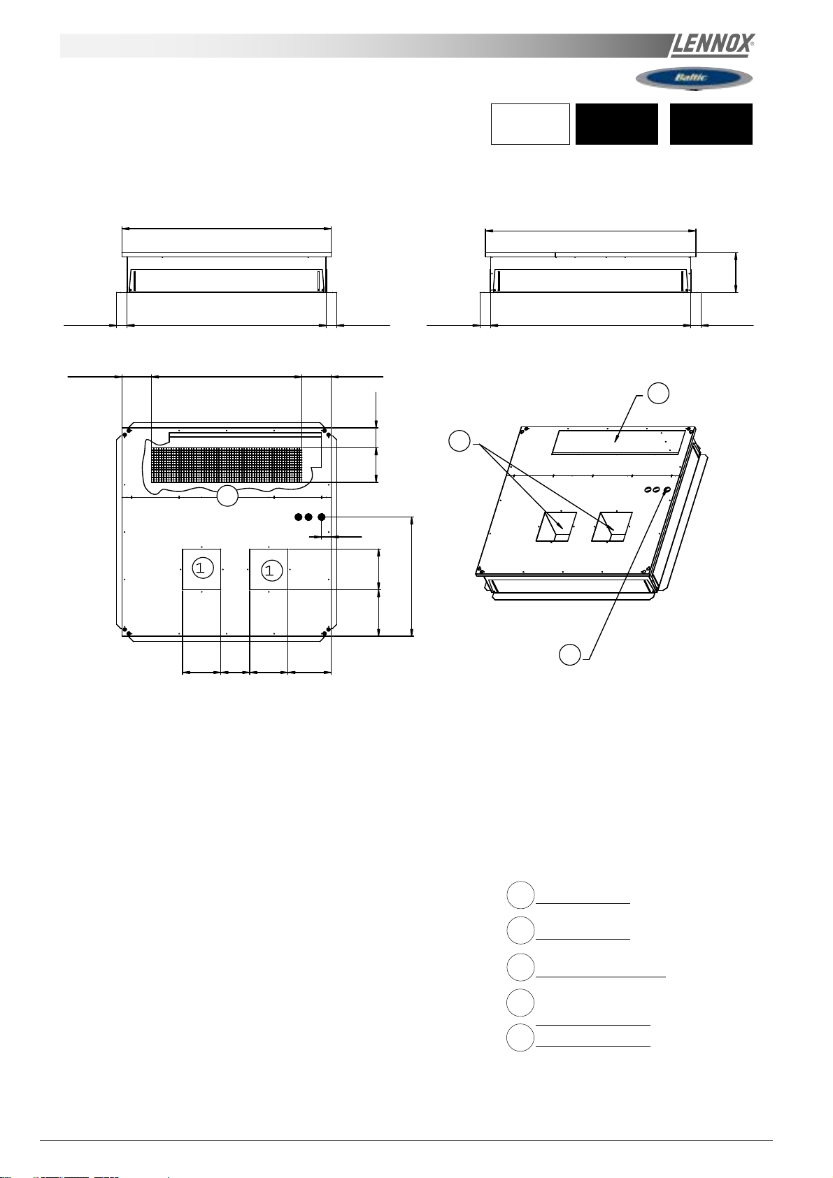
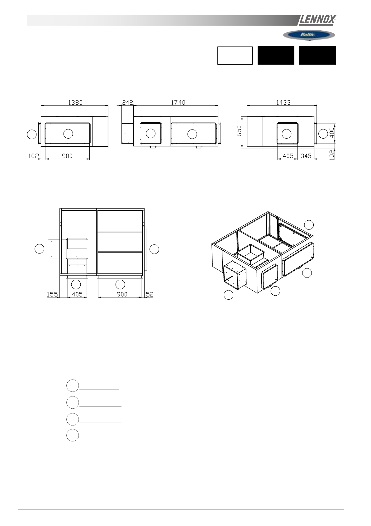
ENERGY RECOVERY OPTION
1201
550
1358
(Under patent INPI May 2004)
1880
488
1
2
020 025
760
FRESH AIR
EXHAUST AIR
1749
FRESH AIR
EXHAUST AIR
641
1380
Part 1 and 2 are supplied loose + Fresh air and extracted air hood closed
Page 42 - IOM / ROOFTOP BALTIC Series - 0704 - E
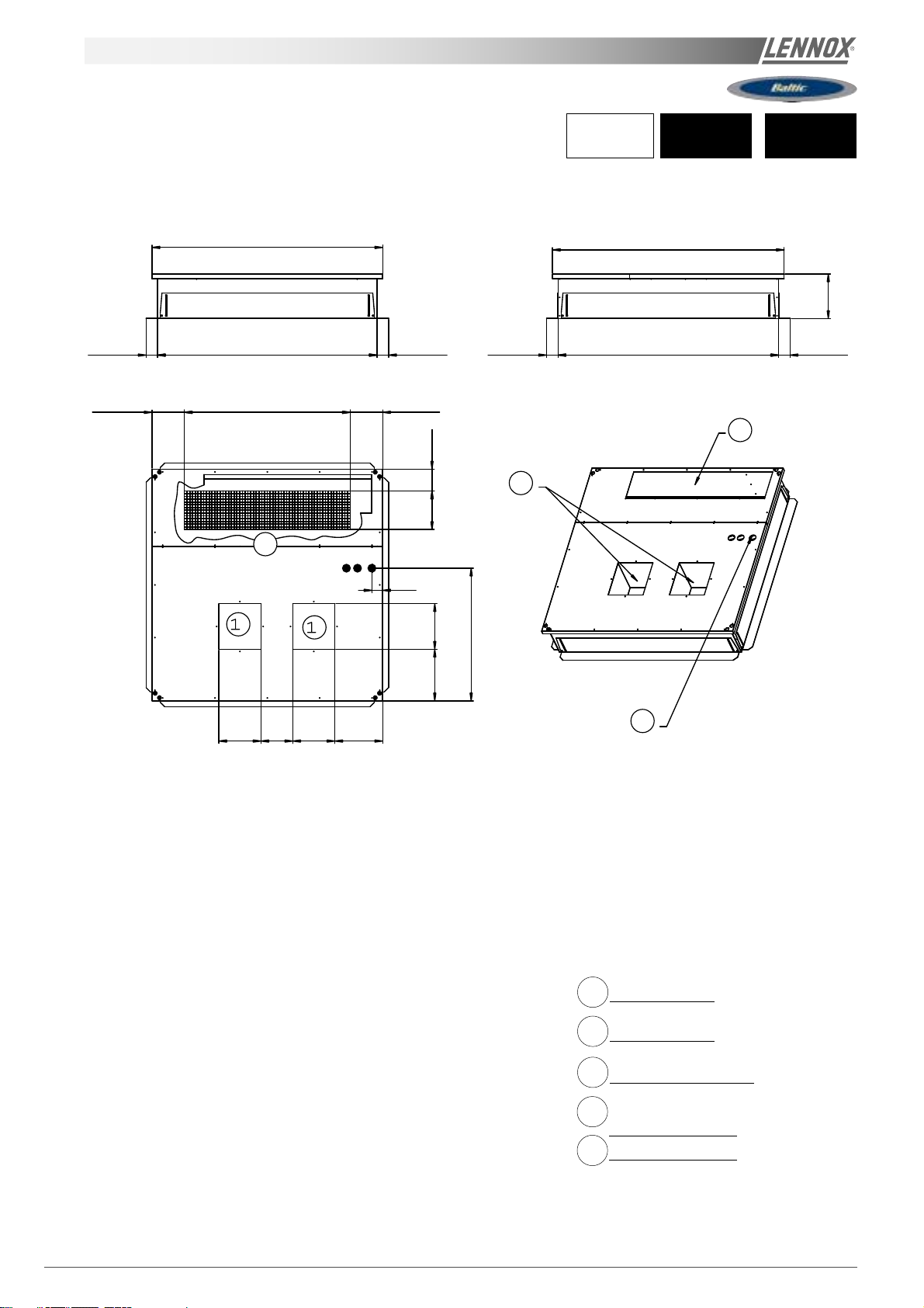
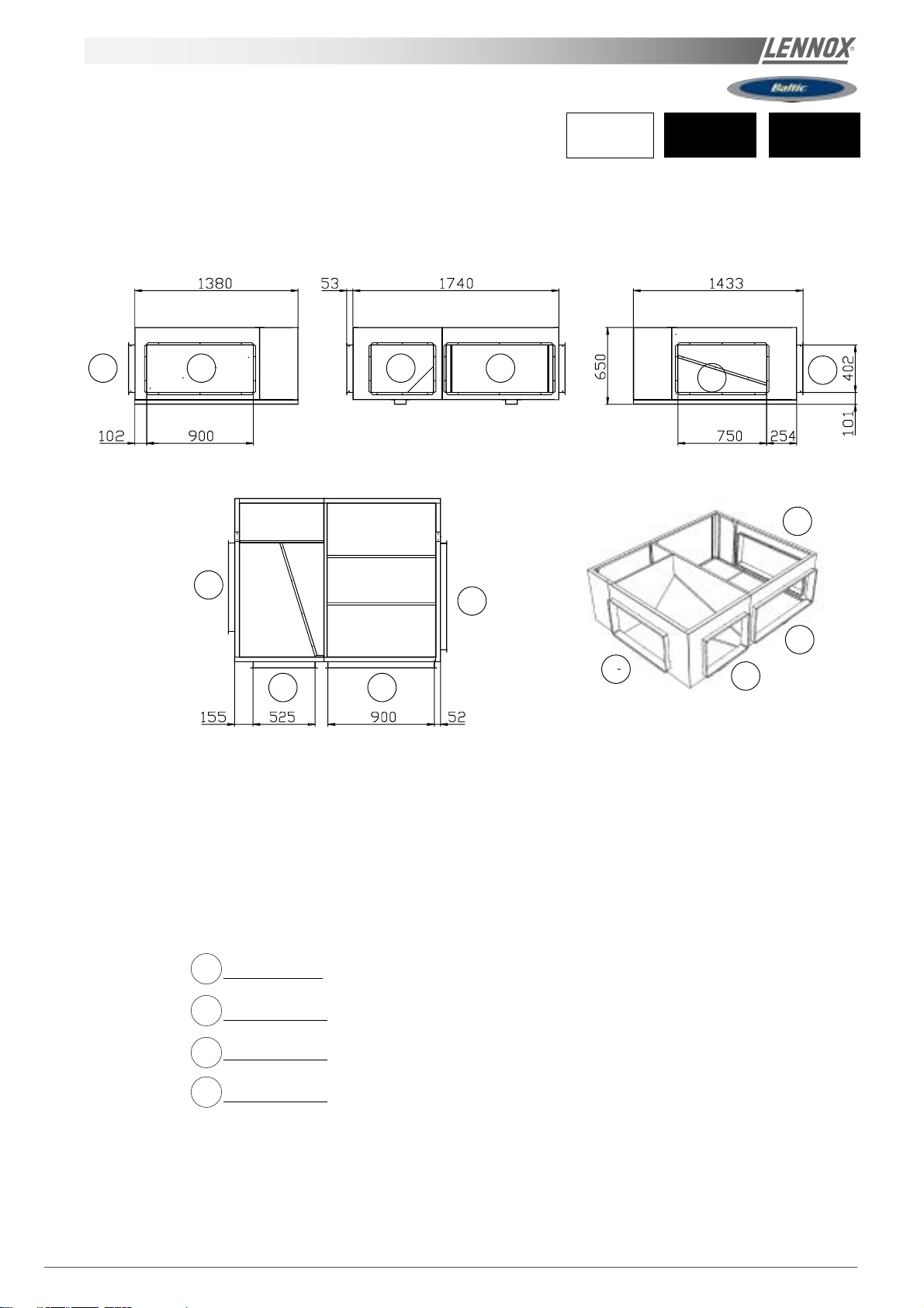
Page 44

ENERGY RECOVERY OPTION
1201
550
1373
(Under patent INPI May 2004)
1880
488
1
2
030 035
1110
FRESH AIR
EXHAUST AIR
1749
FRESH AIR
1380
Part 1 and 2 are supplied loose + Fresh air and extracted air hood closed
EXHAUST AIR
991
IOM / ROOFTOP BALTIC Series - 0704-E Page 43
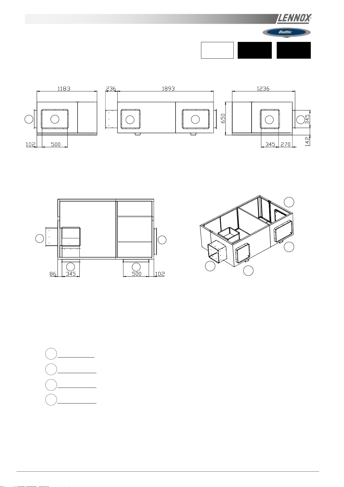
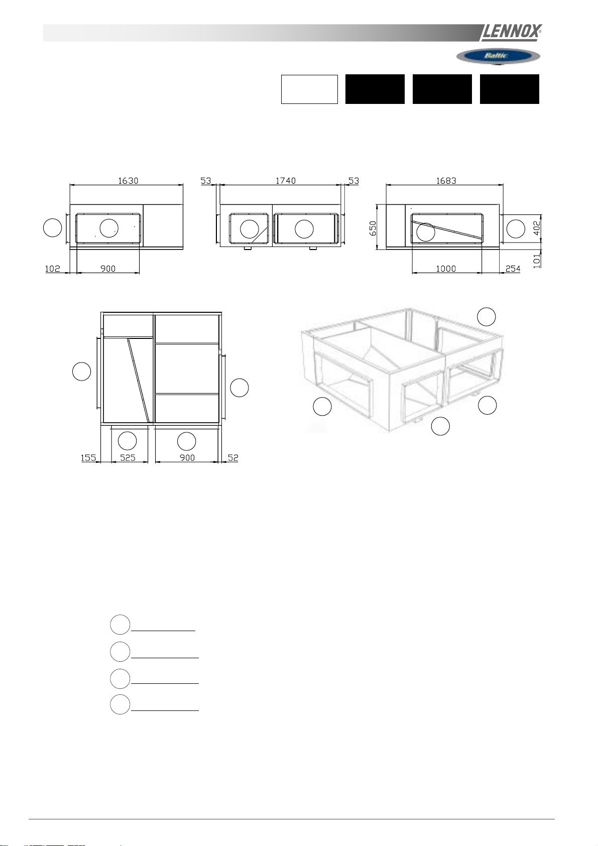
Page 45

ENERGY RECOVERY OPTION
1201550
1373
(Under patent INPI May 2004)
1880
2
1
040 045 050
1487
488
EXHAUST AIR
FRESH AIR
FRESH AIR
EXHAUST AIR
1366
1749
1380
Part 1 and 2 are supplied loose + Fresh air and extracted air hood closed
Page 44 - IOM / ROOFTOP BALTIC Series - 0704 - E
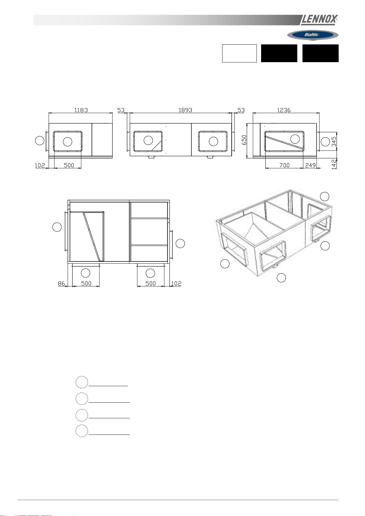
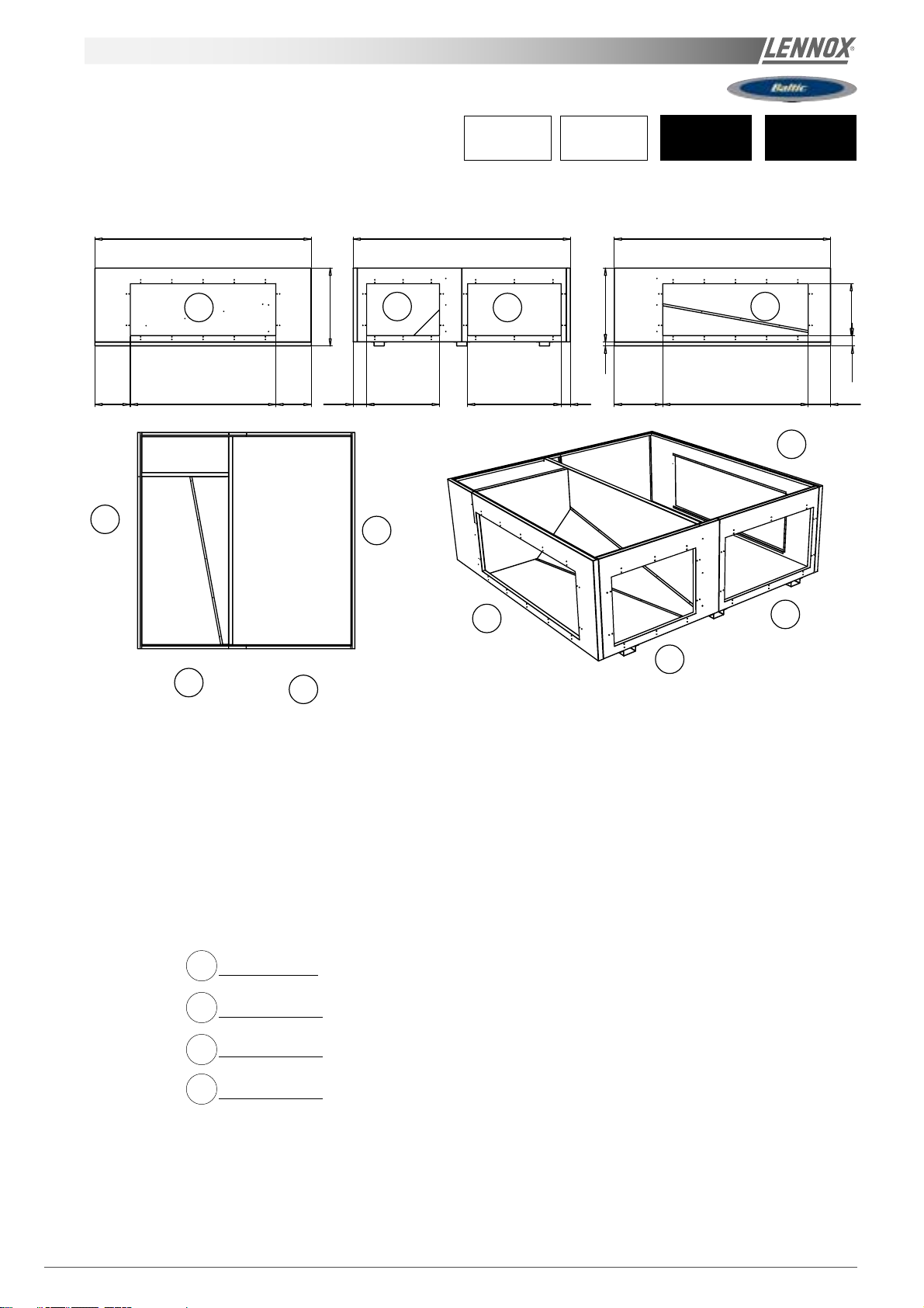
Page 46

ENERGY RECOVERY OPTION
1201550
1373
2
1380
(Under patent INPI May 2004)
1840 1835
488
EXHAUST AIR
1
FRESH AIR
060 070
FRESH AIR
1749
EXHAUST AIR
1716
Part 1 and 2 are supplied loose + Fresh air and extracted air hood closed
IOM / ROOFTOP BALTIC Series - 0704-E Page 45
Page 47

INSTALLATION ON A ROOF MOUNTING FRAMES
D
Energy Recovery
B
Elbow
C
1
A
1) The unit being already erected on the roof curb, position the elbow by plugging the returns (A) in the slits (B) of the
framework of the unit: see detail
2) Fix the elbow with caged nuts at envisaged places (C)
3) Apply mastic on the two side studs and on the superior stud of the energy recovery box.
4) Pose the energy recovery box on the elbow
5) Fix the energy recovery box thanks to the two edges right and left with self-drilling screws (D)
Page 46 - IOM / ROOFTOP BALTIC Series - 0704 - E
1
4
Page 48

ECONOMISER AND EXTRACTION
Economiser
Free cooling can be provided through the use of fresh air
where appropriate rather than cooling excessive amounts of
return air.
The economiser is factory fitted and tested prior to shipment.
It includes two dampers operating from a 24V actuator
Rain hood
It also includes a factory fitted rain hood . Hoods is folded
during transportation to limit risks of damage and must be
unfolded on site as shown below on figure 9 :
Extraction
Installed with economiser assembly, the gravity exhaust
dampers relieve the pressure when outside air is introduced
into the system.
When large amount of fresh air is introduced into the system
power exhaust fans can be used to equalise the pressures.
The extraction fan runs when return air dampers are being
closed and supply air blower is in operation. The extraction
fan runs when outdoor air dampers are at least 50% open
(adjustable value) It is overload protected.
NOTE :
multidirectional roofcurb will be installed
When horizontal flow configuration is required, the
Fig. 9
0-25% fresh air manual (Fig. 10)
It is enough to loosen the
mobile grid's screws and to
make it slip.
0% : screw into limit stop
on the right
25% : screw into limit stop
on the left
BALTIC PRINCIPLE SKETCH
(vertical flow)
2
1
3
ENERGY RECOVERY MODULE + EXHAUST ROOFCURB
PRINCIPLE SKETCH (vertical flow)
2
1
5
Fig. 10
MULTIDIRECTIONAL R OOFCURB
PRINCIPLE SKETCH
2
1
3
4
ENERGY RECOVERY MODULE + EXHAUST ROOFCURB
PRINCIPLE SKETCH (horizontal flow)
2
1
5
6
6
Fresh air
Return air
Exhaust air
Supply air
1 Supply fan
2 Economiser damper
3 Exhaust damper or
Exhaust damper + exhaust fan
4 Multidirectional roofcurb
5 Heat recovery module
6 Exhaust Roofcurb
IOM / ROOFTOP BALTIC Series - 0704-E Page 47
Page 49

COMMISSIONING
THIS WORK MUST ONLY BE CARRIED
OUT BY TRAINED REFRIGERATION
ENGINEERS
FILL THE COMMISSIONNING SHEET AS
YOU GO ALONG
BEFORE CONNECTING THE POWER:
- Ensure that the power supply between the building and
the unit meets local authority standards and that the cable
specification satisfies the start-up and operating conditions.
ENSURE THAT THE POWER SUPPLY
INCLUDES 3 PHASES + NEUTRAL IF THE
UNIT IS EQUIPPED WITH A POWER
EXHAUST FAN
- Check the following wire connections for tightness: Main
switch connections, mains wires linked to the contactors
and circuit breakers and the cables in the 24V control
supply circuit.
How to connect roof curbs and energy recovery module
Cables and their connectors corresponding to the roof
curb' motor and actuator and extraction box' ones are
already rolled up in these elements; it is enough to bring
them through the openings envisaged and to connect
them on the sites indicated on the figure 11.
It's the same procedure when you have an energy recovery
module, as shown on the figure 12.
PRELIMINARY CHECKS
- Ensure that all drive motors are secure.
- Ensure that the adjustable pulley blocks are secure and
that the belt is tensioned with the transmission correctly
aligned. Refer to the next section foe details.
- Using the electrical wiring diagram, check the conformity
of the electrical safety devices (circuit breaker settings,
presence and rating of fuses).
- Check the temperature probe connections.
Connector for the
extraction fan motor
Connector for the
extraction damper motor
Fig. 11
Connector for the Energy recovery
damper and pressure switch
ST ARTING THE UNIT
At this point the unit circuit breakers should be open
You will need a DS50 maintenance controller or Climalook
with appropriate Interface.
LanguageLanguage
Language
LanguageLanguage
ENGLISHENGLISH
ENGLISH
ENGLISHENGLISH
RT 050.001RT 050.001
RT 050.001
RT 050.001RT 050.001
BIOS 0000 Boot 0000BIOS 0000 Boot 0000
BIOS 0000 Boot 0000
BIOS 0000 Boot 0000BIOS 0000 Boot 0000
or
Fig. 12
Page 48 - IOM / ROOFTOP BALTIC Series - 0704 - E
Page 50

COMMISSIONING
The jumpers are factory set and the configuration switches
are adjusted depending on the option the type of unit.
Connecting the CLIMA TIC diplays.
Close the 24V Control Circuit breakers.
Reset the DAD photo (If fitted)
Check and adjust the control settings.
Refer to the control section in this manual to adjust the
different parameters
The CLIMATIC 50 starts after 30s
IOM / ROOFTOP BALTIC Series - 0704-E Page 49
Page 51

COMMISSIONING
POWERING THE UNIT
- Power up the unit by closing the isolator switch (if fitted).
- At this point the blower should start unless the climatic
does not energise the contactor. In this particular case the
blower can be forced by bridging the port NO7 and C7 on
connector J14 on the Climatic. Once the fan is running
check the rotation direction. Refer to the rotation arrow
located on the fan.
- The fans and compressors direction of rotation is
checked during the end of line test. They should therefore
all turn in either the right or wrong direction.
NOTE :
A compressor rotating in the wrong direction will
fail.
- If the fan turns in the wrong direction (the right direction is
shown on figure n° 13), disconnect the main power supply
to the machine at the building's mains switch, reverse two
phases and repeat the above procedure.
- Close all circuit breakers and power up the unit, remove
the bridge on connector J14 if fitted.
- If now only one of the components rotates in the wrong
direction, disconnect the power supply at the machine's
isolator switch (if fitted) and reverse two of the
component's phases on the terminal within the electrical
panel.
- Check the current drawn against the rated values, in
particular on the supply fan (ref. page 53).
- If the readings on the fan are outside the specified limits,
this usually indicates excessive air flow which will affect
the life expectancy and the thermodynamic performances
of the unit. This will also increase the risks of water
ingress into the unit. Refer to the "Air Flow Balancing"
section to correct the problem.
At this point attach the manometers to the refrigerant
circuit.
RUN TEST
Start unit in cooling mode
HIGH PRESSURE
CONNECTION CIRCUIT
N°2
LOW PRESSURE
CONNECTION CIRCUIT
N°2
Thermodynamic readings using manometers and
prevailing environmental conditions
No rated values are given here. These depend on the
climatic conditions both outside and inside the building
during operation. However, an experienced refrigeration
engineer will be able to detect any abnormal machine
operation.
Safety test
- Check Air pressure switch (if fitted) "Dirty filter" detection
test : vary the set-point value (setpoint 3413 on DS50) in
respect to the air pressure value. Observe the response of
the CLIMA TIC™.
- Same procedure for detecting "Missing Filter" (setpoint
3412) or "Air Flow Detection" (setpoint 3411).
- Check the smoke detection function (if fitted).
- Check the Firestat by pressing the test button(if fitted).
- Disconnect the circuit breakers of the capacitor fans and
check the high pressure cut-out points on different
refrigerant circuits.
Page 50 - IOM / ROOFTOP BALTIC Series - 0704 - E
Reverse cycle test
This test is designed to check the good operation of the 4way reversing valves on heat pump reversible systems.
Start the reverse cycle by adjusting the cold or hot
temperature threshold data according to the indoor and
outdoor conditions at the time of test (setpoint 3320).
Fig. 13
Page 52

AP
VENTILATION BELT TENSION
BELT TENSION
On delivery, the drive belts are new and correctly tensioned.
After the first 50 operating hours check and adjust the
tension. 80% of the total elongation of belts is generally
produced during the first 15 hours of operation.
Before adjusting the tension, make sure that the pulleys
are correctly aligned.
To tension the belt, set the height of motor support plate by
moving the plate adjustment screws.
The recommended deflection is 16 mm per metre from
centre to centre.
Check that according to the diagram below (figure 14), the
following ratio remains the same.
A(mm)
P(mm)
= 20
The belts should always be replaced when :
- the disk is set to maximum,
- the belt rubber is worn or the wire is visible.
Replacement belts must have the same rated size as the
ones they are replacing. If a transmission system has
several belts, they must all be from the same
manufacturing batch (compare serial numbers).
NOTE :
An under-tensioned belt will slip, heat and wear
prematurely. On the other hand, if a belt is over-tensioned,
the pressure on the bearings will cause them to over-heat
and wear prematurely. Incorrect alignment will also cause
the belts to wear prematurely.
Fig. 14
IOM / ROOFTOP BALTIC Series - 0704-E Page 51
Page 53

VENTILaTION : PULLEYS
MOUNTING AND ADJUSTING PULLEYS
Fan pulley removal
Remove the 2 screws and put one of them in the extraction
threaded screw.
Screw in fully. The hub and the pulley will separate from
each other.
Remove the hub and the pulley by hand without damaging
the machine.
Fan pulley installation
Clean and de-grease the shaft, hub and conical bore of the
pulley. Lubricate the screws and install the hub and pulley.
Position the screws without turning them.
Place the assembly on the shaft and screw in the screws
alternatively and evenly. Using a mallet or a hammer with a
wooden wedge, tap on the face of the hub to keep the
assembly in place. Torque the screws to 30 Nm.
Take the pulley in both hands and shake it vigorously to
make sure everything is in place.
Fill the holes with grease for protection.
NOTE :
During installation, the key should never protrude
out of its groove.
After 50 operating hours, check that the screws are still in
place.
MOTOR PULLEY INST ALLA TION AND REMOV AL
The pulley is held in position by the key and a screw
located in the groove. After unlocking, removing this screw
by pulling against the shaft spindle (if necessary, use a
mallet and tap uniformly on the hub to remove it).
To assemble, proceed in the reverse order after having
cleaned and de-greased the motor shaft and the pulley
bore.
PULLEYS ALIGNMENT
After adjusting one or both of the pulleys, check the
transmission alignment using a ruler placed on the inner
face of the two pulleys.
NOTE: The warranty may be affected if any major modification is made to the transmission without obtaining our
agreement beforehand.
Page 52 - IOM / ROOFTOP BALTIC Series - 0704 - E
Page 54

VENTILaTION : PULLEYS
The actual resistance of ductwork systems is not always identical to the calculated theoretical values. To rectify this, it may
be necessary to modify the pulley and belt setting. To this effect, the motors are fitted with variable pulleys.
AIRFLOW BALANCING
Measure the absorbed amps
If the absorbed amps are greater than the rated values, the ventilation system has a lower pressure drop than
anticipated. Reduce the flow by reducing the rpm. If the system resistance is significantly lower than design, there is a
risk that the motor will overheat resulting in an emergency cut out.
If the absorbed amps are lower than the rated values, your system has a higher pressure drop than anticipated. Increase
the flow by increasing the rpm. At the same time you will increase the absorbed power which may result in having to
increase the motor size.
To carry out the adjustment and to avoid a time-consuming re-start, stop the machine and if necessary lock the main
switch.
First unscrew the 4 Allen screw(s) on the pulley (see figure 15).
Min Max NB of turns
Pulley Pulley Dia / Dia / from fully Actual diameter (DM) or distance between faces for a given
type External Min Max closed to number of turns from fully closed with SPA belt in (mm)
Diameter Dist Dist fully open
0,5 1 1,5 2 2,5 3 3,5 4 4,5 5,0 5,5
8450 /
D8450 20,2 28 5 21,0 21,8 22,5 23,3 24,1 24,9 25,7 26,4 27,2 28,0 -
8550 /
D8550 20,6 31,2 5 21,6 22,7 23,8 24,8 25,9 26,9 28,0 29,1 30,1 31,2 -
T able 1
The easiest way to determine the fan rotation speed is to
use a tachometer. If not available the fan rpm can be
estimated using the following two methods.
120
136
95 116 5 113,9 111,8 109,7 107,6 105,5 103,4 101,3 99,2 97,1 95,0 -
110 1 3 1 5 128,9 126,8 124,7 122,6 120,5 118,4 116,3 114,2 112,1 110,0
ALLEN WRENCH 4
1st Method with the pulley secured in place:
L
Measure the distance between the two outside faces of the
pulley.
Using table 1 the motor pulley actual diameter can be
estimated
Fig. 15
IOM / ROOFTOP BALTIC Series - 0704-E Page 53
Page 55

VENTILaTION : AIRFLOW BALANCING
2nd method when adjusting the pulley :
-Close the pulley fully and count the number of turns from
fully closed position. Using table 1 determine the motor
pulley actual diameter.
-Record the fix fan pulley diameter.(DF)
-Determine the fan speed using the following formula:
rpm
Where : rpm
FAN
= rpm
MOTOR
MOTOR
x DM / D
F
:from the motor plate or table 2
DM : from table 1
DF: from machine
Once the pulleys are adjusted and the belt checked and
tensioned, start the fan motor and record the Amps and
Voltage between the phases :
Using the measured data and table 2
-Theoretical mechanical power at the fan shaft :
P
= P
meca fan
P
= P
meca fan
P
= V x I x √3 x cosϕ x η
meca fan
meca Motor
x η
elec
x η
meca motor
Transmission
x η
Transmission
meca motor
x η
Transmission
This formula can be approximated in this way
P
= V x I x 1.73 x 0.85 x 0.76 x 0.9
meca fan
With the fan "rpm" and the mechanical power at the fan
shaft an operating point and the supplied airflow can be
estimated using the fan curves.
Table - 3 - Accessories pressure drops
CHECKING AIRFLOW AND ESP
Using the fan curves on page 25, 26, 27, the airflow, the
total pressure available (P
) and the corresponding
TOT
dynamic pressure (Pd) can now be estimated, for a
specific operating point;
The next step consist in estimating the pressure losses
across the unit.
This can be achieved using the "dirty filter pressure
sensor" and the accessories pressure drop table:
Also the pressure drop due to the duct inlet into the rooftop unit can be taken as 20 to 30 Pa.
∆∆
∆P
∆∆
INT
=
∆∆
∆P
∆∆
+ coil + P
filter
Inlet
+
∆∆
∆P
∆∆
Options
using the results from above, the external static pressure
(ESP) can then be estimated:
∆∆
- Pd -
ESP = P
Table 2
MotorSize Nom. Speed Cosϕ η meca motor
0.75 kW 1400 rpm 0.77 0.70
1.1kW 1429 rpm 0.84 0.77
1.5kW 1428 rpm 0.82 0.79
2.2kW 1436 rpm 0.81 0.81
3.0kW 1437 rpm 0.81 0.83
4kW 1438 rpm 0.83 0.84
5.5kW 1447 rpm 0.83 0.86
7.5kW 1451 rpm 0.82 0.87
TOT
∆P
∆∆
INT
SIZE Airflow (Pa) (Pa) (Pa) (Pa) S M H (Pa) (Pa) fresh air (1)
020 3600 28 6 66 46 55 57 59 24 35 161 105
025 4500 43 14 108 66 83 85 88 38 55 247 165
030 5400 26 8 74 59 63 66 69 29 28 172 123
035 6300 36 14 104 76 84 88 91 39 38 230 167
040 7200 28 6 66 6 7 7 4 78 82 25 35 136 98
045 8100 36 10 86 82 91 95 100 32 45 170 124
050 9000 44 14 108 99 110 115 120 3 9 55 207 153
060 10800 2 5 9 8 4 86 61 67 73 29 1 8 198 143
070 12600 3 5 16 117 113 78 85 9 2 40 2 5 266 195
2900 1 8 0 3 9 31 3 7 38 40 16 2 3 108 69
4300 3 9 12 9 8 61 7 6 79 81 35 50 226 151
3600 2 8 6 6 6 46 5 5 57 59 24 35 161 105
5400 6 2 25 160 8 9 117 120 123 55 79 352 238
4300 1 7 1 4 3 40 42 45 47 19 18 113 68
6500 3 8 15 111 80 89 93 96 42 41 244 178
5000 2 2 5 6 2 51 5 5 58 61 25 24 149 105
7600 5 2 24 155 105 119 123 127 58 56 331 243
5800 1 8 0 3 9 46 50 53 57 16 23 92 63
8600 4 0 12 9 8 91 101 106 111 3 6 51 190 139
6500 2 3 3 5 2 56 61 65 69 20 29 113 80
9700 5 1 18 127 113 126 131 137 4 6 64 239 177
7200 2 8 6 6 6 67 7 4 78 82 25 3 5 136 98
10800 63 2 5 160 136 154 160 16 6 56 80 293 220
8600 1 6 3 5 0 58 4 2 47 52 19 1 2 129 91
13000 37 1 8 125 119 82 89 9 7 43 26 282 207
9 950 22 7 70 75 54 59 65 25 16 171 123
14000 56 3 1 194 172 116 125 13 4 65 40 326 240
Economiser Filters Filters Water Coil heater (Pa) roo fcurb directional module module
EU4 F7 Hot Electric Multi- Heat Recovery
(1) to be added to extraction fan ESP
Page 54 - IOM / ROOFTOP BALTIC Series - 0704 - E
Page 56

VENTILaTION : AIRFLOW BALANCING
EXAMPLE
The unit used for this example is a BGK035ND1M with Economiser and Electric Heater type H
It is fitted with a fan which curve is shown on page 57 and a 2.2kW motor.
- Motor rpm: 1430 rpm
- cos ϕ = 0.81
- Voltage = 400V
- Current = 3.77A (measured)
P
mech fan
= V x I x
√√
√ 3 x cos
√√
= 400 x 3.77 x 3 x 0.81 x 0.76 x 0.9 = 1.45kW
The unit is also fitted with a transmission kit 7
- Fixed Fan pulley : 160mm
- Motor adjustable pulley type "8450" opened 4 turns from fully closed or measured distance between pulley end plates is
26.4mm: from table 1 it can be determined that the motor pulley has a diameter of 99.2mm
rpm
= rpm
FAN
x DM / DF = 1430 x 99.2 / 160 = 886 rpm
MOTOR
Using the fan curve below the operating point can be located.
It can be determined that the fan is providing approximately
6300 m3/h with a total pressure P
ϕ ϕ
ϕ x
ϕ ϕ
ηη
η
ηη
mech motor
x
ηη
η
ηη
Transmission
= 530 Pa
TOT
530
1,45
Fig. 36
886
The pressure losses in the unit are
the sum of all pressure drops across
the different parts of a unit :
- Coil and filter (measured) = 104 Pa
- Inlet into the unit = 30 Pa
- Options = 23 Pa for economiser and
91 Pa for electric heater H
∆P = 104 + 30 + 23 + 91 =
248 Pa
The dynamic pressure at 6300m3/h is
given at the bottom of the fan curve P 57
Pd =
81Pa
Hd (mmH2O)
63
The external static pressure available
is therefore
ESP = P
- Pd - ∆PI
TOT
NT
= 530 - 81 - 248 = 201 Pa
IOM / ROOFTOP BALTIC Series - 0704-E Page 55
Page 57

VENTILaTION : AIRFLOW BALANCING
A t12-9s
020-025
Rooftop
Fig. 37
Page 56 - IOM / ROOFTOP BALTIC Series - 0704 - E
Page 58

VENTILaTION : AIRFLOW BALANCING
A t15-11s
030-035
Rooftop
Fig. 38
IOM / ROOFTOP BALTIC Series - 0704-E Page 57
Page 59

VENTILaTION : AIRFLOW BALANCING
A t15-15s
040-045-050
Rooftop
Page 58 - IOM / ROOFTOP BALTIC Series - 0704 - E
Page 60

VENTILaTION : AIRFLOW BALANCING
(*)
Rooftop &
060-070A t15-11G2L
EXHAUST ROOFCURB
070
(*) The performances of twin fan units can be calculated starting from the corresponding operation point for a single fan
(see the figure behind) by applying the formulas below.
- pressure : PTwin = P x 1
- volume flow rate : Qb = Q x 2
- impeller power: Wb = W x 2,15
- fan speed : Nb = N x 1,05
- Lws : Lwsb = Lws + 3 dB
IOM / ROOFTOP BALTIC Series - 0704-E Page 59
Page 61

VENTILaTION : AIRFLOW BALANCING
020-025A t10-10S
EXHAUST ROOFCURB
070
Page 60 - IOM / ROOFTOP BALTIC Series - 0704 - E
Page 62

VENTILaTION : AIRFLOW BALANCING
A t10-8G2L
(*)
030-035
EXHAUST ROOFCURB
070
(*) The performances of twin fan units can be calculated starting from the corresponding operation point for a single fan
(see the figure behind) by applying the formulas below.
- pressure : PTwin = P x 1
- volume flow rate : Qb = Q x 2
- impeller power: Wb = W x 2,15
- fan speed : Nb = N x 1,05
- Lws : Lwsb = Lws + 3 dB
IOM / ROOFTOP BALTIC Series - 0704-E Page 61
Page 63

VENTILaTION : AIRFLOW BALANCING
A t10-10G2L
040-045-050
EXHAUST ROOFCURB
070
Page 62 - IOM / ROOFTOP BALTIC Series - 0704 - E
Page 64

VENTILaTION : AIRFLOW BALANCING
FILTER REPLACEMENT
After opening the filter access panel, lift the filter retaining log.
The filters can then be removed and replaced easily by sliding the dirty filters out and clean ones in.
The CLIMATIC controller can monitor the pressure drop
across the filter (If option fitted)
The following set points can be adjusted depeding on the
installation.
"Airflow" in page 3411 = 25Pa by default
"No filter " in page 3412 = 50Pa by default
"Dirty Filter" in page 3413 = 250Pa by default
The actual pressure drop measured accross the coil can
be read on the Climatic Display DS50 in menu 2131.
The following faults may be identified
-Fault code 0001 AIRFLOW FAILURE, if measured ∆P
across the filter and coil is below the value set in page
3411
-Fault code 0004 DIRTY FILTERS, if measured ∆P across
the filter and coil is above the value set in page 3413
-Fault code 0005 MISSING FILTERS, if measured ∆P
across the filter and coil is below the value set in page
3412
IOM / ROOFTOP BALTIC Series - 0704-E Page 63
Page 65

VENTILaTION : F ANS TART
AIR SOCK CONTROL
FANST ART Operation
The use of air socks for space conditioning allows high air
volumes to be distributed at low velocity and is becoming a
common feature in many applications. To accommodate
this trend, Air-sock control is offered which allows the air
socks to be progressively filled with air on start up. BALTIC
has been enhanced with an electronic device to soft start
the fan. It takes up to 1 minute to go from 0% of air to full air
flow.
This time can be divided in several stages:
- The aim of this first voltage input is to overcome the
resistance of the transmission (Pulleys and belts): 0.5s
and up to 100 rpm
- The second stage is to inflate the air sock: 5 to 30s. and
600 to 900 rpm
Finally the air sock is gradually pressurised during the last
5 to 30 second. The motor reaches nominal speed and the
controller is bypassed.
START-UP
Phase rotation check
If the phase rotation is incorrect the FANSTART Control will
display a fault ( Red LED). Two of the phases must then be
inverted and start again the start up cycle.
The FANSTART control can also display a fixed red
LED in two cases:
- Motor absent (6s)
- A phase is missing (6s)
Any adjustment of the FANSTART has to be done
power stopped.
The motor speed control is achieve through a variation of
the supply voltage of each phase at constant frequency.
The thermal overload limit on the motor imposes a current
limitation during the acceleration stage. Hence if the
selected slope is to steep, the predefined current limit can
be reached: flashing red LED, adjust the potentiometer P3
and the controller will automatically reduce the voltage setpoint accordingly. Then once the current is back under the
high current limit it carries on with the start up cycle.
The green LED switches off itself at the end of the
FANST ART operation.
Red LED
Green LED
P1: pre-inflation
P2: Acceleration
P1: Imax
PotentiometersMotor phases
Switch
Fig. 16
This time is divided in several stages:
- The aim of this first voltage input is to "take
off belts from the pulleys": 0.5s ("BOOST")
- The second stage is to inflate the air sock:
during 30s with approximately half nominal speed
- Finally the air sock is gradually pressurised
during the last 30s. The motor reaches nominal
speed and the controller is shunted, the motor
being fed on line by the tension of the electrical
network.
Current
Over-current limit
st
1
voltage
Input "Boost"
Air sock
Inflation
30s (5s)
Page 64 - IOM / ROOFTOP BALTIC Series - 0704 - E
Acceleration 30s
FANST AR T
off
Page 66

VENTILaTION : F ANS TART
Safety
Excessive "slow down" limit
In the engine's acceleration phase, the red led flashing;
the motor slows down in an excessive way and stops after
80s at fault (led red fixed).
Current protection of the Thyristor
The FANSTART will display a fault (red LED) if the current
exceeds the thyristor current limits:
125A during 0.4s
87.4A during 2s
75A during 6s.
62.5A during 20s.
Start up sequence too long
If at the end of 80s the fanstart did not commutate the
motor on the electrical network, the motor stops: fixed red
led.
Nota :
In the case of a resistant air sock, one can reduce
the phase of pre-inflation to 5 seconds (thanks to the
switch, fig. 16)
FAN ST AR T
OFF
Power + Control ON
Green LED = 1
Red LED = 0
PHASE
ROTA TION
CHECK
OK
INFLA TION
Green LED = 1
Red LED = 0
ACCELERATION
Green LED = 1
Red LED = 0
(If current control ON)
Control Off : V=0
MOTOR OFF
Green LED = 0
Red LED = 0
Control ON
Power OFF
T°C Fault
Thyristor
NOT OK
I > I max
Speed = 0
T > 1 min20s
I < Imin
I > I max
Speed = 0
T > 1 min20s
I < Imin
MOTOR OFF
Green LED = 1
Red LED = 1
CONTROL OFF
motor connected
to mains
IOM / ROOFTOP BALTIC Series - 0704-E Page 65
Page 67

HEATING / HEATING HOT WATER COIL
HYDRAULIC CONNECTIONS
The hot water coil is fitted with a three way proportional
valve and two isolating shut off valves. Two spanners must
be used to tighten the connections. One spanner must
maintain the valve body when connecting the pipe-work to
the main. Failure to do so may damage the pipes joints
and invalidates the warranty.
Filling up and starting the system
- Adjust the control for Heating by reducing the simulated
ambient temperature down to 10°C
- Check that the red indicators located under the valve
actuator are moving correctly with the signal.
red indicators
FREEZE PROTECTION
1) Glycol for freeze protection.
Check the hydraulic system contains Glycol for protection
against freezing.
GL YCOL IS THE ONL Y EFFECTIVE PROTECTION AGAINST
FREEZING
The antifreeze must protect the unit and avoid icing under
winter conditions.
WARNING: Mono-ethylene glycol based fluids may
produce corrosive agents when mixed with air.
2) Drain the installation.
You must ensure that the manual or automatic air bleeders
have been installed on all high points in the system. In
order to drain the system check that all the drain cocks
have been installed on all low points of the system.
HEA TING HOT WA TER COILS FROZEN DUE TO LOW
AMBIENT CONDITIONS ARE NOT COVERED BY THE
WARRANTY.
ELECTROL YTIC CORROSION
Attention is drawn to the corrosion problems resulting from
electrolytic reaction created by unbalanced earth connections.
- Fill the hydraulic system and bleed the coil using the air
vents. Check incoming hot water.
- Check the various connection for possible leaks
ANY COIL DAMMAGED BY ELECTROL YTIC CORROSION IS
NOT COVERED BY THE W ARRANTY
Page 66 - IOM / ROOFTOP BALTIC Series - 0704 - E
Page 68

HEATING / HEATING HOT WATER COIL
Connection HWC B Box Connection HWC C Box
Connection HWC D Box Connection HWC E Box
Pipe internal diameters (DN)
B020 B025 B030 B035 B040 B045 B050 B060 B070
H 202020202525252525
MAXIMUM WORKING PRESSURE: 8bar
MAXIMUM WORKING TEMPERATURE: 1 10°C
IOM / ROOFTOP BALTIC Series - 0704-E Page 67
Page 69

HEATING: ELECTRIC HEATER
GENERAL INFORMA TION
The Baltic electric heaters are stand alone options which
are fitted in the heating section of the unit. As for the hot
water coil or the gas burner this option slides into the
heating compartment located under the supply fan.
In order to reduce the pressure drops the airflow is ducted
around the shielded resistances. The resistances are
made smooth stainless steel tubes with a capacity of 6W/
cm2.
It is protected as standard, against overheat via a high
temperature overload protection set at 90°C and located
less than 150mm after the heater itself.
There are three sizes available for each size of unit:
S: Standard heat
M: Medium heat
H: High heat
The standard and Medium heat electric heaters, are
staged control with 50% or 100%. The high heat versions
is controlled through a fully modulating triac.
380V 400V 415V
Module size (kW) Current (A) Cap (kW) Current (A) Cap (kW) Current (A) Cap (kW)
12 16,3 10,8 17,0 1 1,8 17,8 12,8
24 32,6 21,5 34,0 23,5 35,6 25,6
27 36.7 24.3 38.3 26.6 40.1 28.8
3 6 48,9 32,3 51,1 35,3 53,3 38,4
45 61.1 40.5 63.8 44.3 66.8 48.0
48 65,2 43,0 68,1 47,0 71,1 51,3
54 73,4 48,4 76,6 52,9 80,0 57,7
Page 68 - IOM / ROOFTOP BALTIC Series - 0704 - E
Page 70

HEATING : gas burner
PRELIMINARY CHECKS BEFORE ST ART-UP
NOTE :
ANY WORK ON THE GAS SYSTEM MUST BE CARRIED OUT BY
QUALIFIED PERSONNEL.
THIS UNIT MUST BE INST ALLED IN ACCORDANCE WITH LOCAL
SAFETY CODES AND REGULA TIONS AND CAN ONLY BE USED IN
WELL VENTILLA TED AREA.
PLEASE READ CAREFULL Y THE MANUFACTURER'S INSTRUCTIONS BEFORE STAR TING A UNIT .
BEFORE COMMISSIONING A UNIT WITH GAZ BURNER, IT IS
MANDAT ORY TO ENSURE THA T THE GAZ DISTRIBUTION SYSTEM
(type of gas, available pressure…) IS COMP ATIBLE WITH THE
ADJUSTMENT AND SETTINGS OF THE UNIT.
Check access and clearance around the unit
- Make sure one can move freely around the unit.
- A minimum one-meter clearance must be left in front of
the burnt gas exhaust flue.
- Combustion air inlet and burnt gas exhaust(s) must NOT
be obstructed in any way.
Supply Network Pipe Sizing
MALE THREADED CONNECTION FOR GAZ BURNER: 3/4"
Check that the gas supply line can provide the burners with
the pressure and the gas flow rate necessary to provide
the heating nominal output .
Male threaded connection for Gaz Burner: 3/4"
3
GAS FLOW (for G20 at 20 mbar and 15°C) m
UNIT SIZE 20 25 30 35 40 45 50 60 70
S POWER 2 2 2 23335,75,7
H POWER 3 3 5 566611,511,5
/h
For modulating gas we have just H power for C, D & E-box
- The gas supply to a Rooftop gas unit must be realized
according to Sound Engineering Practice and the local
safety codes and rules.
- In any case the diameter of pipe-work connected to each
Rooftop must not be smaller than the diameter of the
connection on the Rooftop unit.
- Make sure that a shut-off isolation valve has been
installed before EACH Rooftop.
- Check the supply voltage to the exit of the power supply's
transformer T3 of the burner: it must be between 220 and
240V.
STARTING UP THE GAS BURNER
UNIT SIZE 20 25 30 35 40 45 50 60 70
S POWER 1 1 1111111
H POWER 1 1 1111122
Purge the pipe-work near the connection on the ignition
control Valve for a few seconds.
- Check that the unit's treatment "Fan" blower is running.
- Set the control to "ON" This will priorities the gas burner.
- Increase the set temperature (room set point
T able 4 - Standard st art-up Chronology
temperature) to a temperature higher than the actual room
temperature.
Time in seconds
Operations
123456789
11
10
2930313233343536373839404142434445
Control operation sequence
Extraction fan
Smoke extraction fan "ON"
30 to 45 seconds pre-Ventilation
Fire-up spark electrode 4s
Opening of the gas valve
"High Heat"
Flame propagation towards
the ionisation probe
If Ionisation within 5sec:
Normal running
Otherwise fault on gas
ignition control block
After 5 minutes, fault reported
on the climatic controller
If incorrect sequence refer to the fault analysis table to identify the problem.
46
399
400
401
398
IOM / ROOFTOP BALTIC Series - 0704-E Page 69
Page 71

HEATING : gas burner
PRESSURE ADJUSTMENTS ON HONEYWELL
PRESSURE REGULATING V AL VE TYPE VK 4105
Pressure regulator adjustment with 300mbar gas
supply:
High Heat Injection Pressure Checks
- Place the tube of the "accurate" Manometer to the OUT
port on the Gas injector support bar after having loosened
the screw by one turn.
Fig. 17
- The Burner must run in High Heat mode for this check.
- Place the tube of the "accurate" manometer on the Inlet
pressure port (figure 17) of the Gas Regulating Valve after
having loosened the screw by one turn.
LOW HEAT
ADJUSTMENT
Fig. 18
PRESSURE
HIGH HEAT
ADJUSTMENT
UNDERNEATH
INLET
- Check and adjust if necessary the valve Inlet pressure to
20.0 mbar (G20) or 25.0 mbar for Groningue (G25) or 37.0
mbar for propane (G31) after gas burner ignition.(figure 18)
Fig. 19
Check and adjust if necessary the valve OUTLET pressure
to 8.4 mbar (G 20) / 12.3mbar for Groningue (G25) and
31.4 mbar for propane (G31)(figure 19).
Page 70 - IOM / ROOFTOP BALTIC Series - 0704 - E
Page 72

HEATING : gas burner
Low Heat Injection Pressure Checks
- Switch the control to Low Heat
- Check and adjust if necessary the Outlet pressure to 3.5
mbar (G20) and 5 mbar for Groningue(G25) or 14 mbar for
propane (G31) (figure 20).
Pressure adjustments table for each type of gas
Category Supply Low Heat High Heat
pressure injection Injection
G 2 0 20.0 +/-1 3.5 +/-0.1 8.4 +/-0.2
G25 (Groningue) 25.0 +/-1.3 5.0 +/-0.1 12.3 +/-0.2
G31 (GPL) 37.0 +/-1.9 14.0 +/-0.3 31.4 +/-0.6
Valve electrical control
Fig. 20
- After the adjustment of the low heat, re-verify the high heat
- re-position the stoppers and close the pressure ports.
2.90K
- Check these values with an Ohmmeter.
1.69K
Fig. 21
IOM / ROOFTOP BALTIC Series - 0704-E Page 71
Page 73

HEATING : gas burner
BURNER SAFETY CHECKS
Smoke extractor pressure switch Test.
- With the gas burner running, disconnect the flexible tube
fitted to the pressure taping on the pressure switch (fig.
22).
- The Flame must disappear and the extraction fan must
carry on running.
- However, NO fault will be displayed (Gas ignition control
block or CLIMA TIC).
Fig. 22
- After reconnecting the tube, the Burner will restart after a
period of 30 to 45 seconds pre-ventilation.
Ionisation Probe test
-With the gas burner running, disconnect the terminal plug
coming from the ionisation probe to the gas ignition control
box.
-The flame disappears
-The fan is still running and attempting to restart the burner
(restart cycle 30 to 45 seconds).
-if the ignition probe is not reconnected at the end of the
ignition sequence the burner will stop completely.
-The fault light on the gas ignition control block is ON.
-Manually reset the gas ignition control block to eliminate
the fault.
Gas pressure switch test
-With the gas burner running, close the shut off valve
located before the rooftop (fig. 23).
Fig. 23
-The burner stops completely.
-However, No fault light will be displayed on the Gas
ignition control block.. After 6 Minutes, the CLIMATIC will
display a fault.
-Reset the CLIMATIC.
IN CASE OF PROBLEMS REFER TO THE ST ART UP SEQUENCE FLOWCHART NEXT PAGE
Page 72 - IOM / ROOFTOP BALTIC Series - 0704 - E
Page 74

HEATING: gas burner
GAS BURNER FIRE-UP SEQUENCE
Operation from control
Thermostat GAS = Closed
Supply Thermostat Limit ?
(Auto reset)
YES
Gaz low pressure switch?
YES
Gaz ignition control block signal
Extraction Fan ON
Air pressure switch ON
Backfire thermostat ON ?
YES
Pre-ventilation 30 seconds
Fire-up Electrode 4s
Gas valve open
Ionisation 1 second after
the end of sparking ?
YES
NO
NO
NO
NO
Gas control
Valve closes
BURNER
STOPS
Gas control
Valve closes
BURNER STOPS
Fault on Gas
control block
NO
NO
Gas valve remains open
Normal operation
Air press switch ON
or Backfire thermostat ?
YES
Signal from ionisation
probe still ON?
6 minutes Delay
FAUL T ON CLIMATIC
YES
IOM / ROOFTOP BALTIC Series - 0704-E Page 73
Page 75

HEATING : gas burner
GAS BURNER TROUBLESHOUTING
If faults reported on CLIMA TIC
-Reset the CLIMATIC.
-Check voltage: 230V after circuit breaker.
-Check GAS isolation shut-off valves are open.
-Check GAS pressure at the inlet of the GAS valves. It must be >20 mbar when the Burners shut down.
-Adjust the set points to priorities the burner. Increase the value of the room temperature set point to a temperature higher
than actual room temperature.
STAGE NORMAL POSSIBLE POSSIBLE
Heating Green, yellow & L.E.D. OFF opening + Restore
Requested red L.E.D. ON = lack of gas & supply gas supply
L.E.D ON Extraction Fans Nothing happens + Check the free movement
Extraction Fan pre-ventilation Ventilation +Check the good operation + Change the
is ON the fire-up without sparks of the pressure switch pressure switch
Continuous Control Block Box if the Gas
ventilation After a few valve is OK
and sparks seconds the Within 4 seconds + Check the Position and +Check the whole
from fire up gas burner the gas Burner connection of the Ionisation electrical supply
electrode fires-up fires-up BUT Probe. It must not
Page 74 - IOM / ROOFTOP BALTIC Series - 0704 - E
OPERATION F AU LT ACTION SOLUTION
All L.E.D. OFF + Check connections
= fault on the on the blower + Replace
blower thermostat thermostat thermostat
Yellow & red + Check valve's
supply pressure
Red L.E.D.OFF
= fault on the + Check thermostat's + Replace
superheat thermostat operation after ther mostat
on the gas burner manual reset
support bar
After 10 seconds + Check connections of the control
safety shutdown block on the gas valve + Repositioning of
are running + Check impedance of electro the control
by the ignition valve's coils: block on the valve
control block (1) = 2.90k
(2) = 1.69k
+ Check Electrical connection + Replace fan
on the Gas Ignition
on EF connection Board connection
+ Check the Fan supply voltage board If necessary
+ Check the fire-up electrode
+ Check the pressure drop + Re-position the
After 30 to at the pressure switch: pressure switch tube
45 seconds : Continuous It must be higher than 165 Pa
electrode from fire-up using an Ohmmeter and
should spark electrode by artificially creating a
depression in the tube
After 4 seconds + Check injection pressure + Remove the air from
the GAS Burner during start-up the Gas pipe-work
still not operating (Value for High Heat) + Adjust the injection
and safety pressure to
shutdown +Remove the control box high heat value
by the Ignition from the gas block + Change the Control
safety shutdown be Earthed (230V) + Adjust the supply
from the Ignition + Check that R.C circuit and injection pressure
Control Block of the gas burner's if gas is different
transformer is well from natural gas
connected to the neutral polarity G20 :( G25 Gas of
+ Measure the Ionisation Current : Groningue for example)
than 1.5 microAmps.
+ Check the Type of GAS
(fig. n° 21, p 71) valve
of the fan wheel
Control Block and + Replace EF
It must be higher
; + Replace
Page 76

HEATING : gas burner
DISASSEMBLING THE GAS BURNER FOR MAINTENANCE
PURPOSES
Preliminary Safety Recommendations
- Isolate the unit using the main isolator switch.
- Close off the isolating gas valve located before the unit.
- Disconnect the Pipe-work. Do not discard the seals.
Disassembling the gas "burner support bar"
- Disconnect the Electrical Connector on the electric
connection board EF 49
- Remove the two screws which hold the gas Bar in Place
-Carefully remove the gas " burner support bar " avoiding
any damages to the electrodes.
Disassembling the flue
- Electrically disconnect the fan and remove the screws
holding it in place.
-Take care not to loose any cage nuts in the smoke box.
ATTENTION: Check the correct position of the pressure
tube used by the extraction pressure switch.
Required Equipment List for maintenance Adjustment
and Start-up
- An accurate manometer from 0 to 3500 Pa (0 to 350
mbar): 0.1% full scale.
- A Multimeter with Ohmmeter and Micro-amps scale
- An Adjustable Spanner
- Tube Spanner Set: 8, 9, 10, and 13.
- Flat Screwdrivers diameter 3 and 4, Fillips n°1
- Vacuum cleaner
- Paint brush
GAS INJECTORS SUPPORT BAR
IOM / ROOFTOP BALTIC Series - 0704-E Page 75
Page 77

HEATING : gas burner
GAS MODULE-20KW-B-BOX
GAS MODULE-33KW-B-BOX
Page 76 - IOM / ROOFTOP BALTIC Series - 0704 - E
Page 78

HEATING : gas burner
GAS MODULE-20KW-C-BOX
GAS MODULE-46KW-C-BOX
IOM / ROOFTOP BALTIC Series - 0704-E Page 77
Page 79

HEATING : gas burner
GAS MODULE-33KW-D-BOX
GAS MODULE-60KW-D-BOX
Page 78 - IOM / ROOFTOP BALTIC Series - 0704 - E
Page 80

HEATING : gas burner
GAS MODULE-60KW-E-BOX
GAS MODULE-120KW-E-BOX
IOM / ROOFTOP BALTIC Series - 0704-E Page 79
Page 81

HEATING : MODULATING gas burner
MODULATING GAS ( under patent INPI May 2004)
The actuator
Bearing surface of
the actuator's
screw
Maximum opening of the actuator
Actuator screw
Minimum opening of the actuator
The actuator receives an information 0-10V from the
regulation for the positioning of the air shutter; then the
servo-motor transmits its position to the printed-board
which will order the valve.
Check position and operation of the actuator
Disengaging for
hand drive
operation
ST ARTING UP THE GAS BURNER
Purge the pipe-work near the connection on the ignition
control Valve for a few seconds.
- Check that the unit's Treatment Fan Blower is running.
- Set the control to "ON" This will priorities the gas burner.
- Increase the set temperature (room set point
temperature) to a temperature higher than the actual room
temperature.
Manual rotation
of the actuator
Page 80 - IOM / ROOFTOP BALTIC Series - 0704 - E
The start of the gas burner must be done at
injection.
high heat
Page 82

HEATING : MODULATING gas burner
PRESSURE ADJUSTMENTS ON HONEYWELL
PRESSURE REGULATING V AL VE TYPE VK 4105
Pressure regulator adjustment with 300mbar gas
supply:
High Heat Injection Pressure Checks
- Place the tube of the "accurate" Manometer to the OUT
port on the Gas injector support bar after having loosened
the screw by one turn.
Fig. 24
- The Burner must run in High Heat mode for this check.
- Place the tube of the "accurate" manometer on the Inlet
pressure port (figure 24) of the Gas Regulating Valve after
having loosened the screw by one turn.
LOW HEAT
ADJUSTMENT
Fig. 25
PRESSURE
HIGH HEAT
ADJUSTMENT
UNDERNEATH
INLET
- Check and adjust if necessary the valve Inlet pressure to
20.0 mbar (G20) or 25.0 mbar for Groningue (G25) after
gas burner ignition.
(figure 25)
Fig. 26
Check and adjust if necessary the valve OUTLET pressure
to 8.4 mbar (G 20) or 12.3mbar for Groningue (G25)
(figure 26).
IOM / ROOFTOP BALTIC Series - 0704-E Page 81
Page 83

HEATING : MODULATING gas burner
Low Heat Injection Pressure Checks
- Switch the control to Low Heat
- Check and adjust if necessary the Outlet pressure to 1.5
mbar (G20) and 2.25 mbar for Groningue(G25) (figure 27).
- After the adjustment of the low heat, re-verify the high heat
- re-position the stoppers and close the pressure ports.
- After adjustment of the low heat, re-verify the high heat.
Pressure adjustments table for each type of gas (mbar)
Category Supply Low Heat High Heat
pressure injection Injection
G20 20.0 +/-1 3.5 +/-0.03 8.4 +/-0.2
G25 (Groningue) 25.0 +/-1.3 5.0 +/-0.05 12.3 +/-0.2
G31 Non Available Non Available Non Available
Valve electrical control
Fig. 27
2.90K
- Check these values with an Ohmmeter.
1.69K
Page 82 - IOM / ROOFTOP BALTIC Series - 0704 - E
Page 84

HEATING : MODULATING gas burner
BURNER SAFETY CHECKS
Idem non-modulating gas burner
GAS BURNER TROUBLESHOUTING
Idem non-modulating gas burner
MODULA TING-GAZ-46KW-C-BOX
If the valve's flow is not correct, check the operation of the
actuator and of the mechanical assembly.
= Replace the actuator if necessary
DISASSEMBLING THE GAS BURNER FOR MAINTENANCE
PURPOSES
Idem non-modulating gas burner
MODULA TING-GAZ-60KW-D-BOX
IOM / ROOFTOP BALTIC Series - 0704-E Page 83
Page 85

HEATING : MODULATING gas burner
MODULATING-GAZ-120KW -E-BOX
Page 84 - IOM / ROOFTOP BALTIC Series - 0704 - E
Page 86

control software features
CLIMA TIC 50 SOFTWARE FEA TURES AND LOGIC
As a standard feature, CLIMATIC™50 provides 4
scheduling time zones per day on 7 days. On each of the 4
time zones, heating set point, cooling set point, minimum
fresh air, humidity set point high and up, and even the
different authorisations for cooling and heating can be
adjusted.
CLIMATIC™ 50 provides a choice of different remote
displays depending on customer requirement and application of the system. As a standard feature, it is possible to
set alarms (adjustable value low and high) on room
temperature and humidity.
CONTROL SOFTW ARE LOGIC
With the CLIMATIC™ 50 Lennox is going away from the
traditional step control
Capacity factor
It is used to determine the exact capacity required at any
time in order to react quicker and more accurately to any
change in demand.
The capacity factor is a percentage of the total cooling or
heating capacity.
Example:
On a three circuit rooftop unit with two compressors
running out of three has a capacity factor of 66%
In the same way, a three circuit rooftop with a modulating
electric heater running at 20% of its full capacity has a CF:
CF = 25%+25%+25%+5% = 80%
The Capacity factor will increase, decrease, or freeze
depending on the temperature difference between the set
point and the room temperature but also on the way this
room temperature is changing:
∆ Room Temp / Set Point
+4
+2
CAPACITY
FACTOR IS
FROZEN
CAPACITY FACTOR
IS
INCREASED
(ADD CAPACITY)
0
-2
CAPACITY FACTOR
DECREASED
-4
IS
(REDUCE CAP ACITY)
Room Temp / Decreasing
CAPACITY
FACTOR IS
FROZEN
Room Temp / Increasing
Example:
The room set point is 25°C with a 3 compressor unit.
Delta vs
room set Room Cap. COMP COMP COMP
point Temp. factor 1 2 3
+0 Increasing 0% OFF OFF OFF
+1 Increasing 35 % ON OFF OFF
+2 Increasing 70 % ON ON OFF
+3 Increasing 100% ON ON ON
+2 Decreasing 100% ON ON ON
+1 Decreasing 100% ON ON ON
0 Decreasing 100% ON ON ON
-1 Decreasing 60% ON ON OFF
0 Increasing 6 0% ON ON OFF
Reactivity .
The reactivity determines how fast the capacity factor
should vary.
It is given in: Percentage of capacity / Degree °C ( Room
Temp. VS Set Point) / minute
Example :
If the reactivity is set to 3 % / °C / min
Then:
Capacity factor can go from 0 to 30% in 10 minutes if Delta
Room Temp. VS Set Point is 1°C
Or capacity factor will go from 0 to 60 % in 4 minutes if
Delta Room Temp. VS Set Point is 5°C
The reactivity can be adjusted with the CLIMATIC™ 50 The
larger the reactivity the faster the rooftop will react to a
change.
The next table shows the effect of a change of the reactivity
on the capacity factor: This shows that by increasing the
reactivity, the unit reaches the set point quicker but the
energy consumption (capacity factor) is larger.
REACTIVITY : 3
DELT A +5
DELT A +3
DELT A +1
REACTIVITY : 6
DELT A +5
DELT A +3
DELT A +1
15%
9%
75% 100%
45% 90%
1% 15% 30%
1MIN 5MIN 10MIN
30%
18%
2% 30%
1MIN 5MIN 10MIN
100% 100%
90% 100%
60%
IOM / ROOFTOP BALTIC Series - 0704-E Page 85
Page 87

control software features
OTHER FEA TURES
Dynamic Set Point
This feature allows the set point to change according to the
outside temperature.
Example:
If the set point is 25°C
And the dynamic set point is set to 6°C
Then, when the outdoor temperature reaches: 31°C (25°C
+ 6°C) the set point will follow the outdoor temperature with
a 6°C temperature difference.
Set
Point
28˚C
27˚C
26˚C
25˚C
24˚C
23˚C
Dynamic Set point : 6°C
22˚C
26˚C 27˚C28˚C 29˚C 30˚C 31˚C 32˚C 33˚C34˚C
Outdoor Temperature
If you do not want to use this feature, set the dynamic set
point to 99
Time Zones and scheduling
LIST OF SET POINTS CODE CONFORT SERVICE
PER ZONE DISPLAY DISPLA Y
AMBIANT TEMPERATURE
Average set point 3 311 Yes Ye s
Dynamic Set Point 3321 Yes Yes
Cooling Set Point 3322 0 Yes
Heating Set point 3323 0 Yes
Heating Priority 3324 0 Yes
FRESH AIR REHEAT
activated 3331 0 Yes
Heating priority 3332 0 Yes
HUMIDITY
Dehumidification 3341 0 Yes
Humidification 3342 0 Yes
AUTHORIZATION
Free Cooling 0 Yes
Fresh Air by CO2 3354 0 Yes
Mechanical cooling 3355 0 Yes
Mechanical heating 3356 0 Yes
Auxiliary heating 3357 0 Yes
Humidification: ON/OFF 3358 0 Ye s
Low Noise 3359 0 Yes
OTHER
Fan Mode :On / Off 3351 0 Yes
Fan dead 3352 0 Yes
Minimum fresh air (%) 3353 Yes Yes
SCHEDULING
Beginning of the zone for each day
Yes Yes
Start Uno 32 11 Yes Yes
Start.Uno 3212 Yes Yes
Start z.A 3213 Yes Yes
St art.z.A 3214 Yes Yes
Start z.B 3215 Yes Yes
Start.z.B 3216 Yes Yes
Start z.C 3217 Yes Yes
Start.z.C 3218 Yes Yes
With the Climatic50 the scheduling has been completely
reviewed:
* The first day of the week is Monday.
* Automatic switch from winter time to summer time.
* Unoccupied mode from one to seven days
* Three occupied and one unoccupied zone per day
For each zone a series of set points and feature can be
adjusted or selected, depending on the type of display
which is being used.
Page 86 - IOM / ROOFTOP BALTIC Series - 0704 - E
Example of Zone setting :
Table 12
8h00 12h00 14h00 20h00
Monday Unoc. ZA ZB ZC Unoc.
Tuesday
Wed.
Thursday
Friday
Saturday
Sunday
Each zone is determined by its starting time.
Forced modes
3 hours Override
A three hours override period can be forced on the
CLIMATIC
TM
50:
With this feature, a new room temperature set point and
fresh air requirement can be imposed for a three hour
period; It will then revert to the original setting at the end of
the override period or earlier by pressing "esc".
Forced unoccupied zone
The unoccupied zone settings can be forced for a period of
up to seven days. It will then revert to the original settings
at the end of the defined period or earlier by pressing
"esc".
Page 88

control software features
Heating priorities
It is possible to set heating priorities depending on the
outdoor temperature.
For compressors: refer to the instructions 3611, 3612,
3613.
For electrical heater: refer to the instruction 3721.
Example:
It could be decided based on energy costs, that on a dual
fuel unit, it should run in heat pump mode when the
temperature is above 0°C and switch to gas burner below
that point.
Staggered start
After a power cut, the units can be made to restart one after
the other to prevent any current surge.
There is no need for a link between the units, they just
have to be given an address during commissioning and
they will restart 10 seconds x their "address number" after
the power is switched back on.
Example:
If a unit is given the address N°3 it will be switched-on 30
seconds (3 x 10sec) after the power is switched back on.
Fresh air adjustment and calibration on Economiser
The actual fresh air volume brought into the system is not
always proportional to the percentage of opening of the
fresh air damper. That is particularly true when the return
air duct system has been sized to produce excessive
pressure drop.
This often results in bringing into the system an excessive
amount of fresh air, hence increasing the running cost of
the system.
The control of fresh air is now achieved through the use of
three temperature sensors : One in the supply air flow, one
in the return air and one for the outdoor temperature.
Actual
Fresh
Air
Actual
Required
100%
80%
60%
40%
20%
Dynamic Defrost
Temp.
difference
between
Coil
Clean
Coil
Freezing
Coil
Frozen
coil and
outdoor
Defrost cycle start
Highest gradient
Time
This new feature patented under INPI 91.033.063 allows
the unit to start the defrost cycle only when required.
This is achieved through the measurement of the
temperature difference between the coil and the outdoor.
The defrost will be initiated shortly after the Climatic50 has
located the largest gradient in the curve.
The defrost cycle ends when one of these two condition is
completed whichever comes first :
+ Three defrost cycles.
+ 6 minutes.
Alternate defrost
All dual circuits Baltic units have "Alternate Defrost" as a
standard feature.
When one circuit is going through a defrost cycle the
second circuit is running in heat pump mode. This
reduces the need for costly electric heater to maintain the
supply air temperature to an acceptable level of comfort
during the defrost cycles.
CO² Sensor
Where a CO² sensor is connected to the unit, the value of
the fresh air minimum is calculated according to the CO²
ratio. The value measured by the sensor can be read in
variable 2132.
Setpoint 3514 defines the number of ppm up to which the
fresh air minimum is still achieved.
Setpoint 3515 defines the number of ppm from which
100% fresh air is used.
20% 40% 60% 80% 100%
Damper position
Using these three sensors, the Climatic50 will calculate
and memorise the exact percentage of fresh air for each
position of the damper.
T
supply air
= T
return air
x %
Return air
+ T
fresh air
x %
fresh air
The calibration sequence will take place periodically when
all cooling or heating inputs are off. The instruction 3516
permits us to avoid the calibration.
0ppm
Setpoint
3514
IOM / ROOFTOP BALTIC Series - 0704-E Page 87
Setpoint
3515
200ppm
100%
CO2
Page 89

CONTROL INTERFACE DC50
CONTROL INTERFACES AND DISPLA YS
DC50 COMFORT DISPLA Y
This is a remote controller for non-technical customer.
This display gives information such as running mode
status of the fan, set point, % of fresh air and outside air
temperature.
It can be used to set or change the scheduling of the
different time zones, the temperature set point, and the %
of fresh air for each zone. It also has the capacity to set a 3
hours override and to force the unoccupied mode for up to
7 days. It displays the real time clock and different faults
signals.
Display
Type FSTN graphic
Back light: Green LEDs
Resolution 120x32 pixels
Power Supply
Voltage from main Climatic board.
Max power: 0.8W
Installation
The DC50 is designed to be mounted on the wall.
* Fit the cable from the DT50 board through the back
piece
* Fasten the back piece to the wall using the rounded
head screws supplied in the packaging
* Connect the cable from the main board on the RJ12
plug on the back of the DC50 display
* Fasten the front panel on the back piece using the
flush head screws supplied
Finally fit the click-on frame
Jumpers:
"Displays" are supplied directly by the Climatic board with
30Vdc. Take particular care at the path this 30V is taking
when several boards are being used.
J14 and J15 can switch on or off the direct current from the
power supply:
J14 and J15 set between1-2
Connectors A, B, C and screw connector SC are in parallel.
Power supply available to all connectors.
J14 and J15 set between2-3
Connectors B and C are in parallel but line 1 and 6 don't
reach connector A and screw connector SC.
"Displays" connected to these ports will not be powered.
If J14 and J15 are set in different positions the "terminal
connection board" DT50 DOES NOT WORK.
NOTE:
When a shielded wire is used the metallic case of the
"Terminal connection box" DT50 must be earthed.
SC
A
J 15
J 14
1
23
1
2
3
4
5
6
DS50
B
123
RJ12 PIN Connection
06
DT50
DC50
C
DC50
Description
SC Terminals
RJ12 Pin conn
0 + shield / earth
1 1 +VRL=30V
2 2 GND
3 3 Rx- / Tx4 4 Rx+ / Tx+
5 5 GND
6 6 +VRL=30V
T erminal connection Board installation guide DT50
The board is fitted with three "telephone" RJ12 plugs.
Ensure the board is correctly connected.
Standard connection is:
* Climatic on connector C
* DC50 on connector A
* DS50 on connector B
A
B
C
BM 50
OR
J14/J15 on 1-2
6
0
Page 88 - IOM / ROOFTOP BALTIC Series - 0704 - E
Page 90

CONTROL INTERFACE DC50
Terminal display address configuration
The address of the terminal must be checked after having powered
the board.
- To access the configuration mode, press together and old
them for at least 5 seconds.
- The screen shown in
flashing in the top left hand corner.
- To change the address of the terminal display press the key
once.
- Use the keys to select the desired value and confirm by
pressing .
- If the address was changed it will display the screen shown in
Fig29
.
Display adressDisplay adress
Display adress
Display adressDisplay adress
settings ....: nnsettings ....: nn
settings ....: nn
settings ....: nnsettings ....: nn
I/O Board adress:XXI/O Board adress:XX
I/O Board adress:XX
I/O Board adress:XXI/O Board adress:XX
Fig28
will be displayed with the cursor
Display adressDisplay adress
Display adress
Display adressDisplay adress
settings ....: 17settings ....: 17
settings ....: 17
settings ....: 17settings ....: 17
I/O Board adress:XXI/O Board adress:XX
I/O Board adress:XX
I/O Board adress:XXI/O Board adress:XX
Terminal ConfigTerminal Config
Terminal Config
Terminal ConfigTerminal Config
Press ENTERPress ENTER
Press ENTER
Press ENTERPress ENTER
To continueTo continue
To continue
To continueTo continue
Fig. 30
Fig. 28
Display adressDisplay adress
Display adress
Display adressDisplay adress
changedchanged
changed
changedchanged
Fig. 29
Assigning Terminal displays to control boards.
- Access the configuration mode by pressing for at least 5
seconds.
NOTE : To access the board address menu you must go directly to
the bottom of the first screen (shown in
the terminal address as explained above.
- Press the key until the cursor moves to the field "I/O Board
address :XX".
- Use the key to select the correct Climatic board.(N° of Unit)
- Pressing again will display the screen shown in
- Pressing again will display the screen shown in
- The field "P:XX " shows the address of the selected board. In the
example the value "12" has been selected.
- The filed under the "Adr" column represents the addresses of
the terminal displays associated with the board that has the address
"12", while the column under "Priv/Shared " indicate the type of
terminal selected.
Ph: Private
Sh :Shared
Sp : Shared Printer (N/A)
- To exit the configuration procedure and save the data, select the
filed "OK?NO", choose "Yes" using the keys and confirm by
pressing .
If the terminal remains inactive (no button is pressed) for 30 seconds, the configuration procedure is aborted automatically.
Fig 30
Fig30
) without changing
Fig 31
Fig 32
.
.
Keys
Set time
P12:Adr Priv/P12:Adr Priv/
P12:Adr Priv/
P12:Adr Priv/P12:Adr Priv/
SharedShared
Shared
SharedShared
Trm1 17 prTrm1 17 pr
Trm1 17 pr
Trm1 17 prTrm1 17 pr
Trm2 32 shTrm2 32 sh
Trm2 32 sh
Trm2 32 shTrm2 32 sh
Trm3 None --OK? NOTrm3 None --OK? NO
Trm3 None --OK? NO
Trm3 None --OK? NOTrm3 None --OK? NO
Time zone
settings
24.2°C ON24.2°C ON
24.2°C ON
24.2°C ON24.2°C ON
Back to main
Screen or
Cancel
"Override"
FA:20%FA:20%
FA:20%
FA:20%FA:20%
DynFan:AutoDynFan:Auto
DynFan:Auto
DynFan:AutoDynFan:Auto
Out:40.0°C Z:AOut:40.0°C Z:A
Out:40.0°C Z:A
Out:40.0°C Z:AOut:40.0°C Z:A
CoolCool
Cool
CoolCool
Fig. 31
Fig. 32
Increase a
value or go to
"Override
menu"
Change
field or
validate
Decrease a
value or go to
"Override
menu"
IOM / ROOFTOP BALTIC Series - 0704-E Page 89
Page 91

CONTROL INTERFACE DC50
Fan
status
Fan auto
Actual
Fresh Air
Dynamic
Set Point
Room T emp
Activated
24.2°C ON24.2°C ON
24.2°C ON
24.2°C ON24.2°C ON
FA:20% DynFan:AutoFA:20% DynFan:Auto
FA:20% DynFan:Auto
FA:20% DynFan:AutoFA:20% DynFan:Auto
Out:40.0°C Z:A CoolOut:40.0°C Z:A Cool
Out:40.0°C Z:A Cool
Out:40.0°C Z:A CoolOut:40.0°C Z:A Cool
means that fan
will stop if there is no
demand for cooling or
heating.
Pressing the return key on the main screen will display the
following message:
Do you want to :Do you want to :
Do you want to :
Do you want to :Do you want to :
Switch off unit : Switch off unit :
Switch off unit :
Switch off unit : Switch off unit :
Define Unoccupation:NODefine Unoccupation:NO
Define Unoccupation:NO
Define Unoccupation:NODefine Unoccupation:NO
NONO
NO
NONO
Outdoor air
temperature
Override 3 hours :
From main screen press any of the two arrow keys as
shown bellow:
Main screen :
Override menu :
Override 3 hoursOverride 3 hours
Override 3 hours
Override 3 hoursOverride 3 hours
Room SP : 24.0°CRoom SP : 24.0°C
Room SP : 24.0°C
Room SP : 24.0°CRoom SP : 24.0°C
Mini FA : 20%Mini FA : 20%
Mini FA : 20%
Mini FA : 20%Mini FA : 20%
Current
Time zone
Z:A
Z:B
Z:C
Uno
Ove
BMS
24.2°C ON24.2°C ON
24.2°C ON
24.2°C ON24.2°C ON
FA:20%FA:20%
FA:20%
FA:20%FA:20%
DynFan:AutoDynFan:Auto
DynFan:Auto
DynFan:AutoDynFan:Auto
Out:40.0°C Z:AOut:40.0°C Z:A
Out:40.0°C Z:A
Out:40.0°C Z:AOut:40.0°C Z:A
CoolCool
Cool
CoolCool
Unit operating Mode :
Cool or Heat
Increase
Valid /
Go
next line
Pressing the return KEY validates the choice and move to
the next field
Up and down arrows gives you the choice between
different things
If you choose "YES" to the first question the unit is
SWITCHED OFF and you can not access the override
menu.
WARNING : Switching Off the unit disable all safety
Protections
If you choose to stop the Machine number 12 in the
previous screen the following screen will then appear.
12.0 OFF12.0 OFF
12.0 OFF
12.0 OFF12.0 OFF
The unit can then be switched back ON by pressing the
return key once more.
Valid go main
screen
It will revert back to main screen after 15 seconds, if no activity
Switching ON or OFF the unit or forcing a selected time
zone for a period of up to 7 days
24.2°C ON24.2°C ON
24.2°C ON
24.2°C ON24.2°C ON
FA:20% DynFan:AutoFA:20% DynFan:Auto
FA:20% DynFan:Auto
FA:20% DynFan:AutoFA:20% DynFan:Auto
Out:40.0°C Z:A CoolOut:40.0°C Z:A Cool
Out:40.0°C Z:A Cool
Out:40.0°C Z:A CoolOut:40.0°C Z:A Cool
Page 90 - IOM / ROOFTOP BALTIC Series - 0704 - E
Decrease
If the first choose is "NO" then the override screen can be
accessed a particular time zone can be forced for up to 7
days starting from the day "TODAY".
In this menu you can choose the number of days you want
the selected time zone to override.
Increase the number of days by pressing the Up or Down
keys.
Set unoccupation Period:Set unoccupation Period:
Set unoccupation Period:
Set unoccupation Period:Set unoccupation Period:
UNOUNO
UNO
UNOUNO
M T W T F S SM T W T F S S
M T W T F S S
M T W T F S SM T W T F S S
Clock Menu :
From main screen press the clock key, the following menu
appears :
+1 day unoccupied
Valid
-1 day unoccupied
Page 92

CONTROL INTERFACE DC50
Clock Menu :
From main screen press the clock key, the following menu
Increase
12 h 2412 h 24
12 h 24
12 h 2412 h 24
Thursday March 27Thursday March 27
Thursday March 27
Thursday March 27Thursday March 27
Back to Main
"Time Zone" Menu
From main screen press the "Prg" key, the following menu
appears:
Schedule
zone : Azone : A
zone : A
Change
Time zone
It will reverts back to main screen after 15 seconds if no
activity.
"Scheduling" Menu
The scheduling menu can be accessed from the "time
zone" menu by pressing "Prg" again
Change
day
zone : Azone : A
ROOM SP : 24.0°CROOM SP : 24.0°C
ROOM SP : 24.0°C
ROOM SP : 24.0°CROOM SP : 24.0°C
Min FA : 20%Min FA : 20%
Min FA : 20%
Min FA : 20%Min FA : 20%
Back to main
Day : MondayDay : Monday
Day : Monday
Day : MondayDay : Monday
StartStart
Start
StartStart
ZA:8h00 Z.B.12h00ZA:8h00 Z.B.12h00
ZA:8h00 Z.B.12h00
ZA:8h00 Z.B.12h00ZA:8h00 Z.B.12h00
ZC:22h00 uno:22h00ZC:22h00 uno:22h00
ZC:22h00 uno:22h00
ZC:22h00 uno:22h00ZC:22h00 uno:22h00
Valid
Decrease
Increase
Valid /
Go
next line
Decrease
Increase
Valid /
Go
next line
Major Alarm
AMBER
Alarm History Menu
AMBER
You can scroll down this menu using the arrow keys and
select one of the alarm message by pressing the return
key .
Alarm details
This menu allows you to view details on the selected fault
as shown below:
AMBER
RED
24.2°C OFF24.2°C OFF
24.2°C OFF
24.2°C OFF24.2°C OFF
Alarm : MAJORAlarm : MAJOR
Alarm : MAJOR
Alarm : MAJORAlarm : MAJOR
call forcall for
call for
call forcall for
maintenancemaintenance
maintenance
maintenancemaintenance
RED
Alarm 02Alarm 02
Alarm 02
Alarm 02Alarm 02
01-03/03.12h10*12701-03/03.12h10*127
01-03/03.12h10*127
01-03/03.12h10*12701-03/03.12h10*127
0202
02
0202
03-27/02.12h03=12703-27/02.12h03=127
03-27/02.12h03=127
03-27/02.12h03=12703-27/02.12h03=127
03/03 12h05*12503/03 12h05*125
03/03 12h05*125
03/03 12h05*12503/03 12h05*125
Compressor 2Compressor 2
Compressor 2
Compressor 2Compressor 2
HighPres/Elec.PowerHighPres/Elec.Power
HighPres/Elec.Power
HighPres/Elec.PowerHighPres/Elec.Power
03/03.12h05*12703/03.12h05*127
03/03.12h05*127
03/03.12h05*12703/03.12h05*127
RED
Alarm 00Alarm 00
Alarm 00
Alarm 00Alarm 00
Alarms
History
Alarms
Detail
Back to main
Alarm screen
Filter Alarm :
this screen is to clean the filter
AMBER
All keys are locked, the only way to escape
RED
24.2°C ON24.2°C ON
24.2°C ON
24.2°C ON24.2°C ON
Alarm : FilterAlarm : Filter
Alarm : Filter
Alarm : FilterAlarm : Filter
Clean filterClean filter
Clean filter
Clean filterClean filter
Decrease
IOM / ROOFTOP BALTIC Series - 0704-E Page 91
Page 93

control interface dS50
DS50 SERVICE DISPLA Y
This new service display controller is a plug and play
feature but it can also be remotely installed.
Plugging the DS50 will freeze a DC50
Keys
Change
Time zone
Start up screen or Screen(1)
Short cut to
alarm menu
Language Language
Language
Language Language
ENGLISHENGLISH
ENGLISH
ENGLISHENGLISH
RT 050.001RT 050.001
RT 050.001
RT 050.001RT 050.001
BIOS.0000 Boot 0000BIOS.0000 Boot 0000
BIOS.0000 Boot 0000
BIOS.0000 Boot 0000BIOS.0000 Boot 0000
Go back to
screen (1)
LENNOX SERVICELENNOX SERVICE
LENNOX SERVICE
LENNOX SERVICELENNOX SERVICE
TOOLTOOL
TOOL
TOOLTOOL
oror
or
oror
Move up in a
menu or
increase a
value
Move down in
a menu or
decrease
value
Enter
Valid
Select
Moving down the menus
Pressing the arrow keys allows you to move up and down
the menu tree. The selected item changes to CAPITAL letter.
It can then be selected by pressing the "return" or "select"
key .
(0000)01(0000)01
(0000)01
(0000)01(0000)01
1-ALARM1-ALARM
1-ALARM
1-ALARM1-ALARM
2-Data Tuesday2-Data Tuesday
2-Data Tuesday
2-Data Tuesday2-Data Tuesday
3-Setting April 033-Setting April 03
3-Setting April 03
3-Setting April 033-Setting April 03
(0000)01(0000)01
(0000)01
(0000)01(0000)01
1-ALARM1-ALARM
1-ALARM
1-ALARM1-ALARM
2-Data Tuesday2-Data Tuesday
2-Data Tuesday
2-Data Tuesday2-Data Tuesday
3-Setting April 033-Setting April 03
3-Setting April 03
3-Setting April 033-Setting April 03
Sub-menu Data (2000)
Menu reference
ZoneAZoneA
ZoneA
ZoneAZoneA
12h4412h44
12h44
12h4412h44
ZoneAZoneA
ZoneA
ZoneAZoneA
12h4412h44
12h44
12h4412h44
Down
SELECT
Press Prg toPress Prg to
Press Prg to
Press Prg toPress Prg to
startstart
start
startstart
Screen (2) language selection
Language Language
Language
Language Language
ENGLISHENGLISH
ENGLISH
Start
BIOS.0000 Boot 0000BIOS.0000 Boot 0000
BIOS.0000 Boot 0000
BIOS.0000 Boot 0000BIOS.0000 Boot 0000
Five languages are available in addition to English. The
required language must be specified at the time of order.
In this menu the specified language can be selected
using the up and down keys. The "prg" key validates the
choice and start the controller.
Main menu (0000)
Select item
Capital letter
ENGLISHENGLISH
RT 050.001RT 050.001
RT 050.001
RT 050.001RT 050.001
Rooftop Number
oror
or
oror
Current
Time
zone
(2000)01(2000)01
(2000)01
(2000)01(2000)01
1-GENERAL1-GENERAL
1-GENERAL
1-GENERAL1-GENERAL
2-Control2-Control
2-Control
2-Control2-Control
InformationInformation
33
Information
3
InformationInformation
33
Indicates other
menus below
If the menu GENERAL is selected, the controller then
displays a second level sub-menu.
By selecting the item TEMPERATURE and pressing
return, a third level page is displayed as shown bellow:
(2100)01(2100)01
(2100)01
(2100)01(2100)01
1-TEMPERATURE1-TEMPERATURE
1-TEMPERATURE
1-TEMPERATURE1-TEMPERATURE
2-Humidity2-Humidity
2-Humidity
2-Humidity2-Humidity
3-Other3-Other
3-Other
3-Other3-Other
(0000)01(0000)01
(0000)01
(0000)01(0000)01
1-ALARM1-ALARM
1-ALARM
1-ALARM1-ALARM
2-Data2-Data
2-Data
2-Data2-Data
3-Setting April 033-Setting April 03
3-Setting April 03
3-Setting April 033-Setting April 03
Page 92 - IOM / ROOFTOP BALTIC Series - 0704 - E
12h4412h44
12h44
12h4412h44
Tuesday Tuesday
Tuesday
Tuesday Tuesday
ZoneAZoneA
ZoneA
ZoneAZoneA
3 x
(2110)01(2110)01
(2110)01
(2110)01(2110)01
1-OUTSIDE1-OUTSIDE
1-OUTSIDE
1-OUTSIDE1-OUTSIDE
2-Room2-Room
2-Room
2-Room2-Room
3-Supply3-Supply
3-Supply
3-Supply3-Supply
40°C40°C
40°C
40°C40°C
24.5°C24.5°C
24.5°C
24.5°C24.5°C
10.0°C10.0°C
10.0°C
10.0°C10.0°C
Page 94

control interface dS50
Pressing "ESC" at any time sends you back one level up
the menu tree. In the example shown above "ESC" must
be pressed 3 times to go back to the main menu (0000)
Pressing "ESC" will invalidate any changes made to a
value in a setting page.
Alarms
Select the alarm menu using the arrow keys and press
return.
The faults history is then displayed in the page (1000):
RED
RESET
Selected Alarm
Pressing the "ALARM" key resets all the alarms
The number of active alarms goes to 0, no active alarm
shown in the menu, the "bell" key is switched off.
RED
(0000)01(0000)01
(0000)01
(0000)01(0000)01
1-ALARM1-ALARM
1-ALARM
1-ALARM1-ALARM
2-Data Tuesday2-Data Tuesday
2-Data Tuesday
2-Data Tuesday2-Data Tuesday
3-Setting April 033-Setting April 03
3-Setting April 03
3-Setting April 033-Setting April 03
(1000) 01 Alarm 02(1000) 01 Alarm 02
(1000) 01 Alarm 02
(1000) 01 Alarm 02(1000) 01 Alarm 02
01-03/03.12h10*12701-03/03.12h10*127
01-03/03.12h10*127
01-03/03.12h10*12701-03/03.12h10*127
0202
02
0202
03-27/02.12h03 = 12503-27/02.12h03 = 125
03-27/02.12h03 = 125
03-27/02.12h03 = 12503-27/02.12h03 = 125
03/03.12h05*12503/03.12h05*125
03/03.12h05*125
03/03.12h05*12503/03.12h05*125
Alarm Date
and Time
ZoneAZoneA
ZoneA
ZoneAZoneA
12h4412h44
12h44
12h4412h44
Number of
active Alarm
Alarm
code
Active * or
Inactive =
Clock settings
The clock setting menu can be accessed from the main
menu by selecting the menu "SETTING" and then
navigating down through the sub-menus until page 102
(3120).
(3120) 01(3120) 01
(3120) 01
(3120) 01(3120) 01
1-HOUR1-HOUR
1-HOUR
1-HOUR1-HOUR
2-Minute2-Minute
2-Minute
2-Minute2-Minute
3-Day3-Day
3-Day
3-Day3-Day
Selecting the HOUR for displays the page 3121 shown
bellow:
(3121) 01(3121) 01
(3121) 01
(3121) 01(3121) 01
HOUR STD:HOUR STD:
HOUR STD:
HOUR STD:HOUR STD:
Up one
level
Current Setting
Zone Settings
From Main menu (0000) navigate down to sub-menu
"SETTINGS", zone settings (3310).
14h max:2314h max:23
14h max:23
14h max:2314h max:23
"prg" changes
the time zone
(3310) 01(3310) 01
(3310) 01
(3310) 01(3310) 01
Factory
Setting
12h12h
12h
12h12h
44mn44mn
44mn
44mn44mn
44
4
44
Min Setting
min:00min:00
min:00
min:00min:00
Selected Time
Zone.AZone.A
Zone.A
Zone.AZone.A
Validate and
Back One level
Max
Setting
zone
(1000) 01 Alarm 00(1000) 01 Alarm 00
(1000) 01 Alarm 00
(1000) 01 Alarm 00(1000) 01 Alarm 00
01-03/03.12h10 = 12701-03/03.12h10 = 127
01-03/03.12h10 = 127
01-03/03.12h10 = 12701-03/03.12h10 = 127
0202
03/03.12h05 = 12503/03.12h05 = 125
02
03/03.12h05 = 125
0202
03/03.12h05 = 12503/03.12h05 = 125
03-27/02.12h03 = 12503-27/02.12h03 = 125
03-27/02.12h03 = 125
03-27/02.12h03 = 12503-27/02.12h03 = 125
Pressing the "return" key will display details of the
selected alarm
(1100) 01 Alarm 00(1100) 01 Alarm 00
(1100) 01 Alarm 00
(1100) 01 Alarm 00(1100) 01 Alarm 00
03/03.12h05 = 12503/03.12h05 = 125
03/03.12h05 = 125
03/03.12h05 = 12503/03.12h05 = 125
Compressor 2Compressor 2
Compressor 2
Compressor 2Compressor 2
High pres/elec.powerHigh pres/elec.power
High pres/elec.power
High pres/elec.powerHigh pres/elec.power
SELECT
1-ROOM SET :1-ROOM SET :
1-ROOM SET :
1-ROOM SET :1-ROOM SET :
2-Min % FA : 20 %2-Min % FA : 20 %
2-Min % FA : 20 %
2-Min % FA : 20 %2-Min % FA : 20 %
In this particular page, pressing the "prg" key, changes
the time zone. If "ROOM SET" is selected, this displays
the room set point for the specific time zone shown in the
top corner.
(3121) 01(3121) 01
(3121) 01
(3121) 01(3121) 01
Room setRoom set
Room set
Room setRoom set
21.0°C21.0°C
21.0°C
21.0°C21.0°C
Pressing the "prg" validates any changes made, and
move to the next time zone. "ESC" does not validate the
changes and move back one step in the menu tree.
IOM / ROOFTOP BALTIC Series - 0704-E Page 93
24.0°C24.0°C
24.0°C
24.0°C24.0°C
Zone.AZone.A
Zone.A
Zone.AZone.A
min:8.0min:8.0
min:8.0
min:8.0min:8.0
std :20.0std :20.0
std :20.0
std :20.0std :20.0
max:35.0max:35.0
max:35.0
max:35.0max:35.0
Page 95

control communication links
COMMUNICATION LINKS
Master / Slave
Rooftop can now be connected together (up to 12) via a double shielded pair of wire (0.75mm2 not supplied by Lennox)
and use different running modes, as explained bellow, with no cost increase.
BM 50
SERIAL CARD SERIAL CARD SERIAL CARD SERIAL CARD
J11 J10
RT1
LAN LAN
65 34 21
DC50
Cable c.sect.(mm2)
3twisted pair
AWG24
500m maxi
A
J14
3
1
212
-DT50
J15
3
DS50
06
C
B
65 34 21
DC50
Cable c.sect.(mm2)
3twisted pair
500m maxi
1
AWG24
J14
A
3
212
-DT50
J15
3
DS50
BM 50
B
J11 J10
06
C
65 34 21
DC50
RT2
Cable c.sect.(mm2)
2twisted pair
Cable c.sect.(mm2)
3twisted pair
500m maxi
500m maxi
1
AWG24
AWG24
J14
A
3
212
-DT50
J15
3
DS50
BM 50
B
J11
J10 J11 J10
RT3
Cable c.sect.(mm2)
3twisted pair
AWG24
500m maxi
06
C
65 34 21
J14
1
A
3
212
DC50
FAN SET POINT ROOM TEMP
-DT50
J15
3
DS50
BM 50
06
C
B
COOLING HEAT MODE
RT12
1. DC50 MASTER MASTER N/A N/A
2. DC50 Temperature MASTER STAND ALONE MASTER N/A
3 DC50 Average MASTER STAND ALONE AVERAGE N/A
4. Master/Slave Temperature STAND ALONE STAND ALONE MASTER N/A
5. Master/Slave Average. STAND ALONE STAND ALONE AVERAGE N/A
6. Master/Slave Cooling/Heating STAND ALONE STAND ALONE STAND ALONE MASTER
7. Back-up All units are stand alone, one unit is waiting for a failure to start
8 Rolling Back-up All units are stand alone; one unit is waiting for a failure to start.
This back-up unit changes every Tuesday
_ 1 : DC50 : Master slave mode "total"
The master gives the ventilation order, and its set point to
all other rooftops.
_ 2 : DC50 Temperature : Master slave mode
"temperature"
The master gives the ventilation order and its room
temperature/humidity to all other rooftops, but they have
their own set point.
_ 3 : DC50 Average : Master slave mode "average"
The master gives the ventilation order and the room
temperature/humidity used by all rooftop is the average of
all rooftop. Each rooftop has its own set point.
_ 4 : Master/Slave Temperature : Master slave mode
"temperature"
The master gives its room temperature/humidity to all
other rooftops, but they have their own ventilation order &
set point.
Page 94 - IOM / ROOFTOP BALTIC Series - 0704 - E
_ 5 : Master / Slave Average : Master slave mode "ave-
rage"
The room temperature/humidity used by all rooftop is the
average of all rooftop. Each rooftop has its own ventilation
order & set point.
_ 6 : Master / Slave Cooling / Heating : Master slave mode
"cooling/heating"
All rooftop are stand-alone but the slaves have to have the
same running mode as the master (Cooling or heating).
_ 7 : Back-up mode
One rooftop is the back-up unit and will operate if any of the
other rooftop has a failure.
_ 8 : Rolling Back-up mode
Same as above, except the "back-up" unit will be different
each Tuesday. On top of that, the outside temperature/
humidity given to all rooftop can either be the average of
rooftop or be the external humidity/temperature of the
master, making possible the use of a single "weather
station" for the whole site.DS50 Comfort Display / DC50
Service Display
Page 96

control communication links
DS 50 : SERVICE DISPLAY / DC 50 : COMFORT DISPLAY
BM 50
Cable c.sect.(mm2)
3twisted pair
AWG24
500m maxi
06
C
B
3
65 243 1
DC50
A
J14
1
212
3
-DT50
J15
DS50
CLIMALINK / CLIMALOOK
25
J10
BM 50
RT1 RT2
Cable c.sect.(mm2)
3twisted pair
AWG24
500m maxi
-DT50
3
DS50
06
B
65 243 1
DC50
J14
1
A
212
J15
3
J10 J10 J10
Cable c.sect.(mm2)
3twisted pair
AWG24
500m maxi
C
65 243 1
1
A
J14
212
J15
3
DC50
-DT50
3
DS50
06
C
B
RT3 RT12
Cable c.sect.(mm2)
3twisted pair
AWG24
500m maxi
A
-DT50
J14
J15
3
3
1
212
65 243 1
DC50
DS50
BM 50BM 50
06
C
B
SERIAL CARD
BM 50
RT1
RS485 MODBUS
BM 50
SERIAL CARD SERIAL CARD SERIAL CARD
RT2
RT3
BM 50BM 50
RS485 MODBUS
LON WORKS FTT 10A LON WORKS FTT 10A
Cable c.sect.(mm2)
two wire S12E RANCING
from mini 0.2 to max 2.5mm°
AWG20/22
1000m maxi
RS485
RS232
230V
TELEPHONE
CLIMALOOK
CLIMALINK
IOM / ROOFTOP BALTIC Series - 0704-E Page 95
SERIAL CARD
+
-
2
3
Connect a 120 ohms 1/4 W
end line resistor
ONLY MODBUS
GND
1
RT12
BM50
Page 97

BM50 addressing
Mandatory operation if the units are
connected with each other
(Master/Slave link).
unit : - -unit : - -
unit : - -
unit : - -unit : - -
Press at the same time during a few seconds
Then you will see the screen as below.
Display addressDisplay address
Display address
Display addressDisplay address
Setting………………: 32Setting………………: 32
Setting………………: 32
Setting………………: 32Setting………………: 32
I/O Board address:--I/O Board address:--
I/O Board address:--
I/O Board address:--I/O Board address:--
pLAN address : 1pLAN address : 1
pLAN address : 1
pLAN address : 1pLAN address : 1
UP: increaseUP: increase
UP: increase
UP: increaseUP: increase
DOWN: decreaseDOWN: decrease
DOWN: decrease
DOWN: decreaseDOWN: decrease
ENTER: save & exitENTER: save & exit
ENTER: save & exit
ENTER: save & exitENTER: save & exit
Switch off the unit and then switch on.
Press at the same time during a few seconds
Then you will see the screen as below.
Increase
Decrease
Press the key until the cursor moves to the field
"Display address setting"
Use the key to select the required value
(usually "00") and confirm by pressing .
Display addressDisplay address
Display address
Display addressDisplay address
Setting………………: 00Setting………………: 00
Setting………………: 00
Setting………………: 00Setting………………: 00
I/O Board address:--I/O Board address:--
I/O Board address:--
I/O Board address:--I/O Board address:--
If the address has been changed it will display the screen shown
as below.
Display addressDisplay address
Display address
Display addressDisplay address
changedchanged
changed
changedchanged
Switch off the unit and then switch on.
Wait for a few seconds
Display addressDisplay address
Display address
Display addressDisplay address
Setting………………: 00Setting………………: 00
Setting………………: 00
Setting………………: 00Setting………………: 00
I/O Board address:--I/O Board address:--
I/O Board address:--
I/O Board address:--I/O Board address:--
Press the key until the cursor moves to the field "Display address
setting"
Use the key to select the required value (usually "32") and
confirm by pressing .
Display addressDisplay address
Display address
Display addressDisplay address
Setting………………: 32Setting………………: 32
Setting………………: 32
Setting………………: 32Setting………………: 32
I/O Board address:--I/O Board address:--
I/O Board address:--
I/O Board address:--I/O Board address:--
Disconnect the DS50 from the unit and then reconnect it.
Service terminalService terminal
Service terminal
Service terminalService terminal
Wait to connectWait to connect
Wait to connect
Wait to connectWait to connect
######################################
###################
######################################
######################################
###################
######################################
During this message, press &
seconds until the new screen appears.
Use the key to select the required value for pLAN address (for
example "2") and confirm by pressing .
Page 96 - IOM / ROOFTOP BALTIC Series - 0704 - E
SelftestSelftest
Selftest
SelftestSelftest
Please waitPlease wait
Please wait
Please waitPlease wait
at the same time during a few
Then you just have to indicate the number of the unit.
unit : - -unit : - -
unit : - -
unit : - -unit : - -
Page 98

control interfaces ds50 menu tree
Main Screen Code Description Code Description Code Description Code UNIT Min Factory Max
1-Alarm 1000 # 1100 # 1110 # 1111
2-Data 2000 1-General 2100 1-Temperature 2110 Outside 2111 °c
Room 2112 °c
Supply 2113 °c
Return 2114 °c
2-Humidity 2120 Outside 2121 %.
Room 2122 %.
Outside 2123 g/Kg
Room 2124 g/Kg
3-Other 2130 Air Pres. 2131 pa
CO2 2132 p p m
Sw On/Off 2133 On/Off
Sw Reset 2134 On/Off
Sw Unoc. 2135 On/Off
4-Out. Custom. 2140 BM50.1 2141 On/Off
BE50.1 2142 On/Off
BE50.2 2143 On/Off
BE50.3 2144 On/Off
BE50.4 2145 On/Off
5-In. Custom. 2150 BM50.1 2151 On/Off
BM50.2 2152 On/Off
BE50.1 2153 On/Off
BE50.2 2154 On/Off
BE50.3 2155 On/Off
BE50.4 2156 On/Off
6-In.% Custom. 2160 BE50.1 2161 °c
BE50.2 2162 °c
BE50.3 2163 °c
BE50.4 2164 °c
BE50.1 2165 %.
BE50.2 2166 %.
BE50.3 2167 %.
BE50.4 2168 %.
2-Control 2200 1-Room 2210 Sp Cool 2211 °c
Sp Heat 2212 °c
Capa Cool 2213 %
Capa Heat 2214 %
Sw Dis.Cool 2215 On/Off
Sw Dis.Heat 2216 On/Off
2-Reheat 2220 Set Point 2221 °c
Capacity 2222 %
3-Humidity 2230 Sp Dehu 2231 %
Sp Humi 2232 %
Capa Dehu 2233 %
Capa Humi 2234 %
4-TCB 2240 S w G 2241 On/Off
Sw Y1 2242 On/Off
Sw Y2 2243 On/Off
Sw W1 2244 On/Off
Sw W2 2245 On/Off
Sw B 2246 On/Off
IOM / ROOFTOP BALTIC Series - 0704-E Page 97
Page 99

control interfaces ds50 menu tree
Outside T. / Schedule / Defrost]
State 2312 List [Stopped / Schedule / Fault / Start]
Sw State 2313 On/Off
Fire/Smoke 2314 On/Off
Relay 2315 On/Off
3-Fan 2300 1-Ventilation 2310 Config. 2311 List [No / 500pa / 100pa]
Main Screen Code Description Code Description Code Description Code UNIT Min Factory Max Description
Low Speed 2316 On/Off
Sw Speed 2317 On/Off
2-Extraction 2320 State 2321 List [Stopped / Schedule / Fault / St art]
Relay 2322 On/Off
3-Condenser 1 2330 Config. 2331 List [No / Yes]
State 2332 List [Stopped / Schedule / Fault / Start]
Sw State 2333 On/Off
Relay 2334 On/Off
4-Condenser 2 2340 Config. 2341 List [No / Yes]
State 2342 List [Stopped / Schedule / Fault / Start]
Sw State 2343 On/Off
Relay 2344 On/Off
5-Condenser 3 2350 Config. 2351 List [No / Yes]
State 2352 List [Stopped / Schedule / Fault / Start]
Sw State 2353 On/Off
Relay 2354 On/Off
6-Condenser 4 2360 Config. 2361 List [No / Yes]
State 2362 List [Stopped / Schedule / Fault / Start]
Sw State 2363 On/Off
State 2412 List [Stopped / Air Flow / St art / Enthalpy /
Relay 2364 On/Off
Mini.Air 2413 %
Modulat. 2414 %
4-Cooler 2400 1-F r e s h A i r 2410 Config. 2411 Lis t [No / 0%-50% / Modulation / 100%]
Opening 2415 %
Calib. 2416 Yes/No
Page 98 - IOM / ROOFTOP BALTIC Series - 0704 - E
Page 100

control interfaces ds50 menu tree
/ Switch / Fault (2) / Fault (1) / Ant-Sho-Cy
/ Start / Start Heat / Defrost]
State 2422 List [Stopped / Air Flow / Start]
Opening 2423 %
2-Cold W/Coil 2420 Config. 2421 List [No / Modulation]
Main Screen Code Description Code Description Code Description Code UNIT Min Factory Max Description
Defrost T 2513 °c
Sw State 2514 On/Off
State 2512 List [Stopped / Air Flow / Outside T. / Schedule
5-Compressor 2500 1-Compressor 1 2510 Config. 2511 Lis t [No / C. only / H.only]
Sw Low P. 2515 On/Off
Relay 2516 On/Off
H.Pump 2517 On/Off
Sw Disable 2518 On/Off
Run Time 2519 h
2-Compressor 2 2520 Config. 2521 List
State 2522 List
Defrost T. 2523 °c
Sw State 2524 On/Off
Sw Low P. 2525 On/Off
Relay 2526 On/Off
H.Pump 2527 On/Off
Sw Disable 2528 On/Off
Run Time 2529 h
State 2532 List
Defrost T. 2533 °c
Sw State 2534 On/Off
Sw Low P. 2535 On/Off
Relay 2536 On/Off
H.Pump 2537 On/Off
Sw Disable 2538 On/Off
Run Time 2539 h
3-Compressor 3 2530 Config. 2531 List
IOM / ROOFTOP BALTIC Series - 0704-E Page 99
 Loading...