

Lennox BAH020SNM, BAG045SSM, BAM020SHM, BAM045SSM, BAC030SNM Installation, Operating And Maintenance
...Page 1
Providing indoor climate comfort
BALTIC R410A
BALTIC R410A-IOM-0708-E
Installation, operating
and maintenance
Page 2
CONTENTS
BALTIC R410A-IOM-0708-E Page 1
INSTALLATION – OPERATING – MAINTENANCE
MANUAL
Ref. BALTIC-IOM-0708-E
The present manual applies to the following ROOFTOP versions:
BAC020SNM BAH020SNM BAG020SHM BAG045SSM BAM020SHM BAM045SSM
BAC030SNM BAH030SNM BAG020SSM BAG055SHM BAM020SSM BAM055SHM
BAC035SNM BAH035SNM BAG030SHM BAG055SSM BAM030SHM BAM055SSM
BAC045SNM BAH045SNM BAG030SSM BAG065DHM BAM030SSM BAM065DHM
BAC055SNM BAH055SNM BAG035SHM BAG065DSM BAM035SHM BAM065DSM
BAC065DNM BAH065DNM BAG035SSM BAG075DHM BAM035SSM BAM075DHM
BAC075DNM BAH075DNM BAG045SHM BAG075DSM BAM045SHM BAM075DSM
NOTES FOR UNIT FITTED WITH GAS BURNER:
THE UNIT MUST BE INSTALLED IN ACCORDANCE WITH LOCAL SAFETY
CODES AND REGULATIONS AND CAN ONLY BE USED IN WELL
VENTILLATED AREA.
PLEASE READ CAREFULLY THE MANUFACTURER’S INSTRUCTIONS
BEFORE STARTING THIS UNIT.
THIS MANUAL IS ONLY VALID FOR UNITS DISPLAYING THE FOLLOWING
CODES: GB IR GR DA NO FI IS
In case these symbols are not displayed on the unit, please refer to the technical
documentation which will eventually detail any modifications required to the
installation of the unit in a particular country.
LENNOX have been providing environmental solutions since 1895, our range of Baltic TM rooftop continues to meet the
standards that have made LENNOX a household name. Flexible design solutions to meet YOUR needs and
uncompromising attention to detail. Engineered to last, simple to maintain and Quality that comes as standard. Information
on local contacts at www.lennoxeurope.com.
All the technical and technological information contained in this manual, including any drawing and technical descriptions
provided by us, remain the property of Lennox and must not be utilised (except in operation of this product),
reproduced, issued to or made available to third parties without the prior written agreement of Lennox.
The technical information and specifications contained in this manual are for reference only. The manufacturer reserves
the right to modify these without warning and without obligation to modify equipment already sold.
Page 3

CONTENTS
BALTIC R410A-IOM-0708-E Page 2
COMMISSIONING REPORT............................................................................................. 5
INSTALLATION
Transport - Handling ...........................................................................................11
Mandatory handling devices................................................................................12
Dimensions and weights .....................................................................................13
Lifting the units ...................................................................................................14
Lifting the roofcurbs ............................................................................................15
Lifting the energy recovery module ..................................................................... 16
Preliminary checks .............................................................................................17
Minimum clearances around the unit ...................................................................18
Installation on roof mounting frames ....................................................................19
Positioning roofcurb ................................................................ .................19
Non adjustable Non assembled roof curb ................................ .................20
Securing the curb ....................................................................................22
Curbing and flashing ................................ ................................ ................22
Heat recovery installation ................................ ................................ .........23
Economiser and extraction ................................................................................. 24
COMMISSIONING
Electrical connections.......................................................................................... 26
Preliminary checks .............................................................................................26
Starting the unit...................................................................................................27
Powering the unit ................................................................................................ 28
ARRANGEMENT DRAWINGS
BALTIC BAC-BAH-BAG-BAM 020 to 075.............................................................29
Non adjustable roofcurb ..................................................................................... 37
Adjustable roofcurb ............................................................................................38
Multidirectional horizontal roofcurb....................................................................... 42
Exhaust vertical roofcurb.....................................................................................46
Exhaust horizontal roofcurb ................................................................ .................50
Transition roofcurb..............................................................................................53
Energy recovery option........................................................................................54
VENTILATION
Belt tension ........................................................................................................58
Mounting & adjusting pulleys ..............................................................................59
Airflow balancing ................................................................ ................................60
Filters ................................ ................................ ................................ ................71
Fan starter .........................................................................................................72
Page 4

CONTENTS
BALTIC R410A-IOM-0708-E Page 3
HEATING OPTIONS
Hot water coils ................................ ................................ ................................ ...73
Electric heater ................................................................ ................................ ....75
Gas burners .......................................................................................................76
Modulating gas burners................................................................ .......................88
CLIMATIC CONTROLLER
See specific content on page 93 ................................ ................................ .........93
PRINCIPLE SKETCHES
Refrigerant circuits .............................................................................................114
Hot water coil diagram ........................................................................................ 117
MAINTENANCE DIAGNOSTIC
........................................................................................118
MAINTENANCE PLAN ....................................................................................................121
WARRANTY ....................................................................................................................124
CERTIFICATES ...............................................................................................................125
Page 5

PRESSURE EQUIPMENT
BALTIC R410A-IOM-0708-E Page 4
All Baltic Units are compliant with the PED directive 97-23/CE
The following note must be followed carefully
All work on the unit must be carried out by a qualified and authorised employee.
Non-compliance with the following instructions may result in injury or serious accidents.
Work on the unit:
The unit shall be isolated from the electrical supply by disconnection and locking using the main isolating switch.
Workers shall wear the appropriate personal protective equipment (helmet, gloves, glasses, etc.).
Work on the electrical system:
Work on electric components shall be performed with the power off (see below) by employees having valid electrical
qualification and authorisation.
Work on the refrigerating circuit(s):
Monitoring of the pressures, draining and filling of the system under pressure shall be carried out using connections
provided for this purpose and suitable equipment.
To prevent the risk of explosion due to spraying of coolant and oil, the relevant circuit shall be drained and at zero pressure
before any disassembly or unbraz ing of the refrigerating parts takes place.
There is a residual risk of pressure build-up by degassing the oil or by heating the exchangers after the circuit has been
drained. Zero pressure shall be maintained by venting the drain connection to the atmosphere on the low pressure side.
The brazing shall be carried out by a qualified brazier. The brazing shall comply with standard NF EN1044 (minimum 30%
silver).
Replacing components:
In order to maintain CE marking compliance, replacement of components shall be carried out using spare parts, or using
parts approved by Lennox.
Only the coolant shown on the manufacturer’s nameplate shall be used, to the exclusion of all other products (mix of
coolants, hydrocarbons, etc.).
CAUTION:
In the event of fire, refrigerating circuits can cause an explosion and spray coolant gas and oil.
Page 6
COMMISSIONING REPORT
BALTIC R410A-IOM-0708-E Page 5
Site details / Informations site
Site / Site
Unit Ref/ N° Affaire
Installer/ Installateur
………………………………………
……………………………………....
………………………………………
Controller/ Contrôleur
Model/Model
Serial No/ No Série
Refrigerant / Réfrigérant
………………………………….
……………….…………………
…………………………………
…………………………………
(1) ROOF INSTALLATION / INSTALLATION SUR LE TOIT
Sufficient Access OK / Accès Suffisants
Yes/Oui No/ Non
Condensate drain fitted / Drainage condensats
Installé Yes/Oui No/ Non
Roofcurb / Costière
OK Not OK/PasOK
(2) CONNECTIONS CHECK / VERIFICATIONS DE RACCORDEMENTS
Phase check/ Vérification des Phases
Yes / Oui No / Non
Voltage between Phases
Tension entre Phases
1 / 2
……………….
2 / 3
……………….
1 / 3
……………….
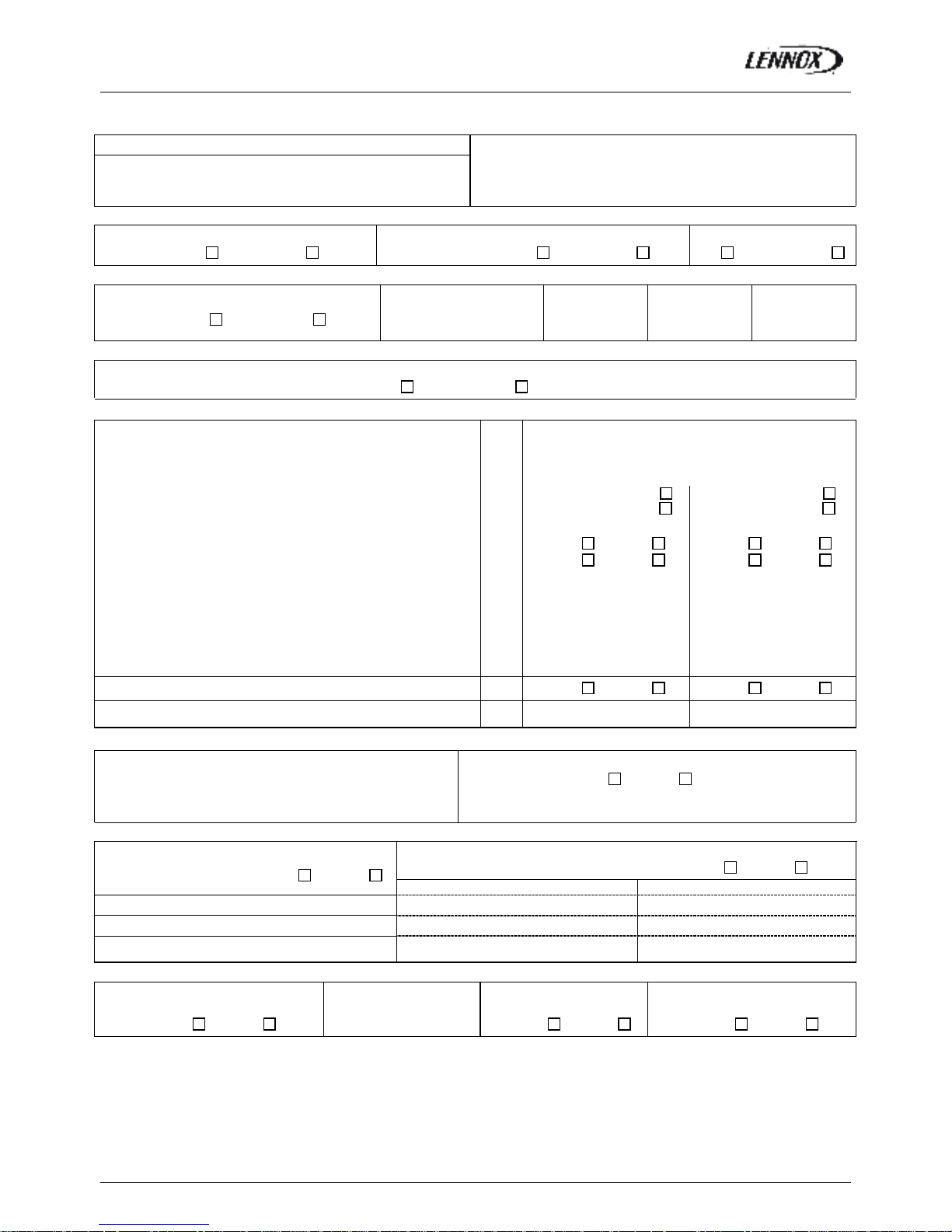
(3)CLIMATIC CONFIGURATION CHECK / VERIFIER LA CONFIGURATION CLIMATIC
CLIMATIC 50 Configured according to the Options and Specifications / CLIMATIC 50 configuré en fonction des options et des
spécifications: Yes/Oui No/ Non
(4) SUPPLY BLOWER SECTION / VENTILATION TRAITEMENT
Type / Type:
Power displayed on plate / Puissance affichée sur la plaque:
Voltage displayed on plate / Tension affichée sur la plaque:
Current displayed on plate / Intensité affichée sur la plaque:
KW
V
A
N°1
……………………
……………………
……………………
N°2
……………………
……………………
……………………
Fan Type / Type de Ventilateur: Forward / Action
Backward / Réaction
Forward / Action
Backward / Réaction
Displayed Belt Length / Longueur Courroie affichée: mm …………………… ……………………
Tension Checked/ Tension Vérifiée: Yes/Oui No/ Non Yes/Oui No/ Non
Alignment Checked / Alignement Vérifié: Yes/Oui No/ Non Yes/Oui No/ Non
Motor Pulley Dia/ Poulie Moteur Dia: DM mm …………………… ……………………
Fan Pulley Dia/ Poulie Ventilateur Dia: DP mm …………………… ……………………
Fan Speed / Vitesse rotation Ventilateur = Motor rpm x DM / DP
Averaged Measured Amps / Intensité Mesurée moyenne:
rpm
A
……………………
……………………
……………………
……………………
Shaft Mechanical Power (Refer to airflow balancing)
Puissance Mécanique à l’Arbre (Voir section réglage débit)
W …………………… ……………………
Operating point checked / Vérif. Point de fonctionnement: Yes/Oui No/ Non Yes/Oui No/ Non
Estimated Airflow / Estimation Débit d’Air m
3
/h …………………… ……………………
(5) AIRFLOW PRESS. SENSOR CHECK / VERIF. DES SECURITES PRESSOSTATS D’AIR
Measured pressure drop / Pertes de charge au pressostat
…………………………… mbar
Set Points Adjusted / Changement des consignes:
Yes/Oui No/ Non
If Yes enter new values/ Si oui noter les nouvelles consignes:
3410: ………… 3411: ………… 3412: …………
(6) EXTERNAL SENSOR CHECKS / VERIFICATION DES CAPTEURS EXTERNES
Check and record temp. in menu 2110 / Vérifier et mesurer les
températures. Dans menu 2110: Yes/Oui No/ Non
Check electrical connections / Vérification des
connections électriques: Yes/Oui No/ Non
100% Fresh Air / 100% Air neuf 100% return Air / 100% Air repris
Supply Temperature / Température Soufflage ………………………..°C ………………………..°C
Return Temperature / Température reprise ………………………..°C ………………………..°C
Outdoor Temperature / Température extérieure ………………………..°C ………………………..°C
(7) MIXING AIR DAMPERS CHECKS / VERIFICATIONS VOLETS DE MELANGE
Dampers open & close freely/
Volets s’ouvrent et se ferment OK
% Minimum FA:
%minimum Air Neuf:
Power exhaust checked/
Ventilateur extraction
Enthalpy sensor(s) checked/
Control enthalpie installé
Yes/Oui No/ Non ……………..% Yes/Oui No/ Non Yes/Oui No/ Non
Page 7

COMMISSIONING REPORT
BALTIC R410A-IOM-0708-E Page 6
(8) REFRIGERATION SECTION / SECTION REFRIGERATION
Outdoor Fan Motor Current / Intensité Moteurs Batterie externe: Check Rotation
Motor 1 / Moteur 1 L1 ……..A L2 ……..A L3 ……A Yes/Oui No/ Non
Motor 2 / Moteur 2 L1 ……..A L2 ……..A L3 ……A Yes/Oui No/ Non
Compressor
Voltage/ Tension
Compresseur.
Motor 3 / Moteur 3 L1 ……..A L2 ……..A L3 ……A Yes/Oui No/ Non Comp1: …….. V
Motor 4 / Moteur 4 L1 ……..A L2 ……..A L3 ……A Yes/Oui No/ Non Comp2: …….. V
Motor 5 / Moteur 5 L1 ……..A L2 ……..A L3 ……A Yes/Oui No/ Non Comp3: …….. V
Motor 6 / Moteur 6 L1 ……..A L2 ……..A L3 ……A Yes/Oui No/ Non Comp4: …….. V
Compressor Amps COOLING / Intensité
Compresseur MODE FROID
Pressures & Temperatures / Pressions & températures
Temperatures / Temperatures Pressures / Pressions
Phase 1 Phase 2 Phase 3
Suction/ Asp
Disch / refoul
LP/ BP
HP / HP
Comp 1 …..… A …..… A …..… A ……… °C ……… °C ……… Bar ……… Bar
Comp 2 …..… A …..… A …..… A ……… °C ……… °C ……… Bar ……… Bar
Comp 3 …..… A …..… A …..… A ……… °C ……… °C ……… Bar ……… Bar
Comp 4 …..… A …..… A …..… A ……… °C ……… °C ……… Bar ……… Bar
Check Reversing valves./
Vérifier vannes d’inversion:
Valve1/Vanne1: Yes/Oui No/ Non
Valve2/Vanne2: Yes/Oui No/ Non
Valve3/Vanne3: Yes/Oui No/ Non
Valve4/Vanne4: Yes/Oui No/ Non
Compressor Amps HEATING / Intensité
Compresseur en Pompe à Chaleur
Pressures & Temperatures / Pressions & températures
Temperatures / Temperatures Pressures / Pressions
Phase 1 Phase 2 Phase 3
Suction/ Asp
Disch / refoul
LP/ BP
HP / HP
Comp 1 …..… A …..… A …..… A ……… °C ……… °C ……… Bar ……… Bar
Comp 2 …..… A …..… A …..… A ……… °C ……… °C ……… Bar ……… Bar
Comp 3 …..… A …..… A …..… A ……… °C ……… °C ……… Bar ……… Bar
Comp 4 …..… A …..… A …..… A ……… °C ……… °C ……… Bar ……… Bar
HP cut out / Coupure HP ……Bar LP cut out / Coupure sécurité BP ………..…... Bar
Refrigerant charge / Charge réfrigérant C1 : ………..kg C2 : ………..kg C3 : ………..kg C4 : ………..kg
(8)ELECTRIC HEATER SECTION / SECTION RECHAUFFEUR ELECTRIQUE
Type / Type: …………………………………………………. Serial No/ No Série.:………………………..
AMPS 1st stage (Baltic) / Intensité 1er étage (Bal tic) AMPS 2nd stage (Baltic) / Intensité 2e étage (Baltic)
1 ………………. 2 ………………. 3 ………………. 1 ………………. 2 ………………. 3 ……………….
(9) HOT WATER COIL SECTION / SECTION BATTERIE EAU CHAUDE
Check Three Way Valve Movement / Vérification Mouvement Vanne trois voies: Yes/Oui No/ Non
(10) GAS HEATING SECTION / RAMPE GAZ
Gas Burner N°1 / Brûleur gaz N°1 Gas Burner N°2 / Brûleur gaz N°2
Size / Taille:
……………………….
Valve type / Type vanne:
…………………….
Size / Taille:
……………………….
Valve type / Type vanne:
…………………….
Pipe size/ tuyauterie: Gas type / Type gas : G……. Pipe size/ tuyauterie Gas type / Type gas : G…….
Line press./ press. ligne :
………………………
Drop test / test pression
Yes/Oui No/ Non
line press./ press. ligne :
………………………
Drop test / test pression
Yes/Oui No/ Non
Check manifold pressure/ Pression injection:
High fire/Grande allure…….…Low fire/Petite allure………..
Check manifold pressure/ Pression injection:
High fire/Grande allure…….…... Low fire/Petite allure………..
Pressure cut out airflow press switch / Pression coupure
pressostat débit d’air : ……………………mbar /Pa
Pressure cut out airflow press switch / Pression coupure
pressostat débit d’air : ……………………mbar /Pa
Motor amps
I moteur:
……….A
Flue temp /
temp fumées
……… °C
CO2 %:
………%
CO ppm:
………%
Motor Amps
I Moteur:
……….A
Flue temp /
temp fumées
………. °C
CO2 %:
………%
CO ppm:
………%
(11) REMOTE CONTROL BMS CHECK / VERIFICATIONS BMS CONTROL A DISTANCE
Type / Type:
…………………………..
Sensor type / Type Capteur
………………………………..
Interconnect wiring checked:
Yes/Oui No/ Non
It is recommended that you fill the two tables below before transferring the zone settings to the Climatic controller.
Page 8
COMMISSIONING REPORT
BALTIC R410A-IOM-0708-E Page 7
Il est recommandé de remplir les deux tableaux ci-dessous avant de transférer les consignes de zones vers le contrôleur
Climatic50.
Refer to control section page 55 / Se référer à la section régulation page 55
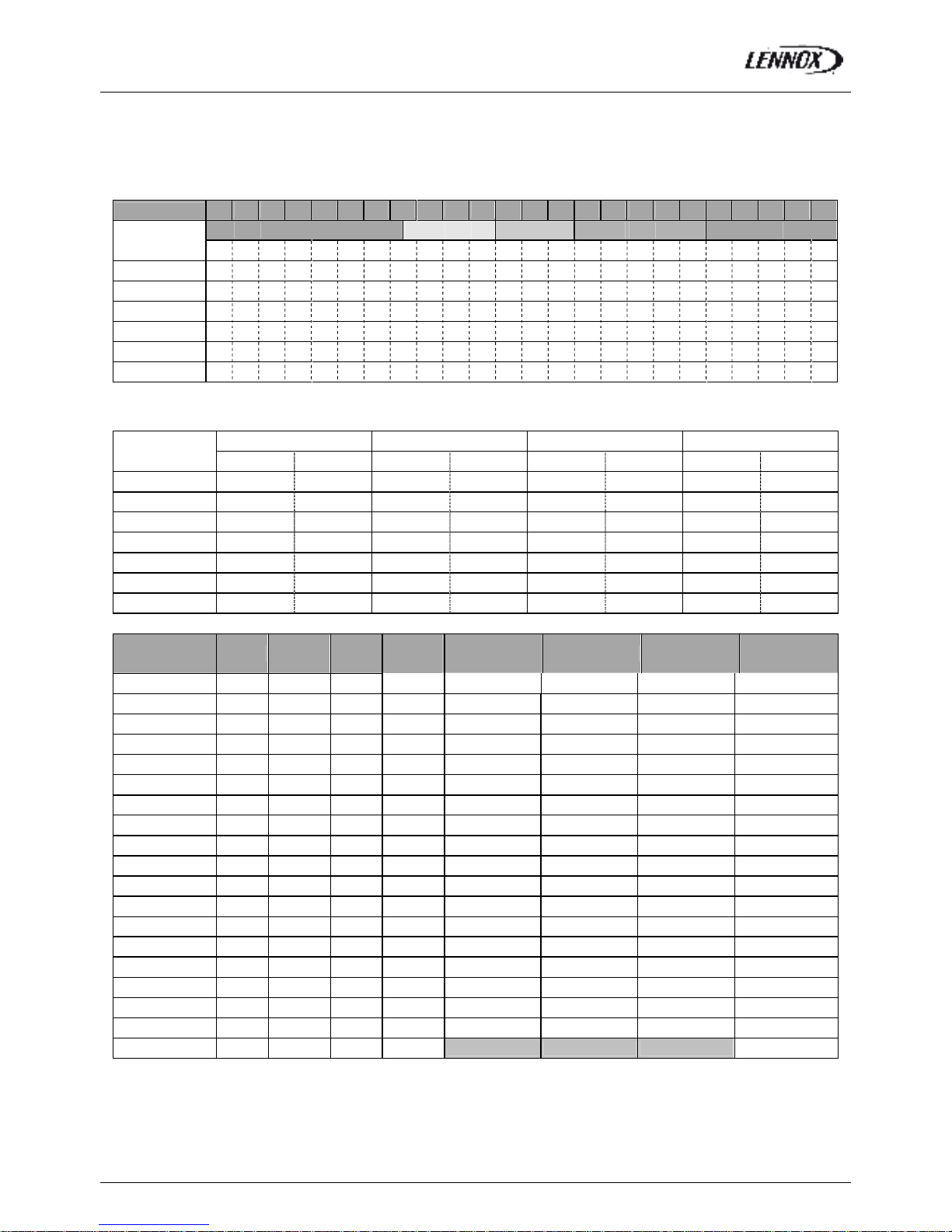
Time Zones / Zones Horaires
Hour
0 1 2 3 4 5 6 7 8 9 10 11 12 13 14 15 16 17 18 19 20 21 22 23
Example
UNO
7h15
ZA
11h00
ZB
14h00
ZC
19h00
UNO
Monday
Tuesday
Wednesday
Thursday
Friday
Saturday
Sunday
Variables to adjust for each time zone / Consignes à renseigner pour chaque zone horaire
Start z.A Start z.B Start z.C Start UNO
hour (3211) min (3212) hour (3213) min (3214) hour (3215) min (3216) hour (3217) min (3218)
Monday
Tuesday
Wednesday
Thursday
Friday
Saturday
Sunday
Description Unit Menu Min
Max
Zone A Zone B Zone C UNOC
Sp Room °C 3311 8 35
Mini.Air % 3312 0 100
Sp Dyna °C 3321 0 99.9
Sp Cool °C 3322 8 35
Sp Heat °C 3323 8 35
Swap Heater On/Off 3324 ~ ~
Activation On/Off 3331 ~ ~
Swap Heater On/Off 3332 ~ ~
Sp.Dehu % 3341 0 100
Sp.Humi % 3342 0 100
Fan On/Off On/Off 3351 ~ ~
Fan Dead On/Off 3352 ~ ~
F.Air On/Off 3353 ~ ~
CO2 On/Off 3354 ~ ~
Comp.Cool. On/Off 3355 ~ ~
Comp.Heat. On/Off 3356 ~ ~
AuxHeat On/Off 3357 ~ ~
Humidif. On/Off 3358 ~ ~
Low Noise On/Off 3359 ~ ~ N/A N/A N/A
COMMENTS:……………………………………………………………………………………………………………………………………
…………………………….……………………………………………………………………………………………………………………….
Page 9

COMMISSIONING REPORT
BALTIC R410A-IOM-0708-E Page 8
REFRIGERANT TRANSACTIONS LOGBOOK:
EC Regulation No 842/2006
GENERAL INFORMATION
Site Name
Serial Number
Site Address
Site Operator
Cooling Load
Refrigerant
Type
Refrigerant Quantity (kg)
Unit
Manufacturer
Year of Installation
REFRIGERANT ADDITIONS
Date Engineer Quantity (kg) Reason for Addition
REFRIGERANT REMOVAL
Date Engineer Quantity (kg) Reason for Removal
LEAK TESTS
Date Engineer Test Result Follow Up Action Required
Page 10

COMMISSIONING REPORT
BALTIC R410A-IOM-0708-E Page 9
LEAK TESTS (Part 2)
Date Engineer Test Result Follow Up Action Required
FOLLOW UP ACTIONS
Date Engineer Related to test dated Action Taken
TESTING of AUTOMATIC LEAK DETECTION SYSTEM (If fitted)
Date Engineer Test Result Comments
Remarks: ………………………………………………………………………………………………
………………………………………………………………………………………………………………
………………………………………………………………………………………………………………
………………………………………………………………………………………………………………
………………………………………………………………………………………………………………
……………………………………………………………………………………………………………………………………………………
…………………………………………………………………………………………..…………………………………………………………
………………………………………………………………………………………..……………………………………………………………
.………………………………………………………………………………………..………………………………………………………….
………………………………………………………………………………………..……………………………………………………………
.………………………………………………………………………………………..………………………………………………………….
Page 11

COMMISSIONING REPORT
BALTIC R410A-IOM-0708-E Page 10
………………………………………………………………………………………..……………………………………………………………
.………………………………………………………………………………………..………………………………………………………….
………………………………………………………………………………………..……………………………………………………………
.………………………………………………………………………………………..………………………………………………………….
………………………………………………………………………………………..……………………………………………………………
.………………………………………………………………………………………..………………………………………………………….
………………………………………………………………………………………..……………………………………………………………
.………………………………………………………………………………………..………………………………………………………….
………………………………………………………………………………………..……………………………………………………………
.………………………………………………………………………………………..………………………………………………………….
………………………………………………………………………………………..……………………………………………………………
.………………………………………………………………………………………..………………………………………………………….
………………………………………………………………………………………..……………………………………………………………
.………………………………………………………………………………………..………………………………………………………….
………………………………………………………………………………………..……………………………………………………………
.………………………………………………………………………………………..………………………………………………………….
………………………………………………………………………………………..……………………………………………………………
.………………………………………………………………………………………..………………………………………………………….
………………………………………………………………………………………..……………………………………………………………
.………………………………………………………………………………………..………………………………………………………….
………………………………………………………………………………………..………………………………………………………….
………………………………………………………………………………………..………………………………………………………….
………………………………………………………………………………………..……………………………………………………………
.………………………………………………………………………………………..………………………………………………………….
………………………………………………………………………………………..……………………………………………………………
.………………………………………………………………………………………..………………………………………………………….
………………………………………………………………………………………..……………………………………………………………
.………………………………………………………………………………………..………………………………………………………….
………………………………………………………………………………………..……………………………………………………………
.………………………………………………………………………………………..………………………………………………………….
………………………………………………………………………………………..……………………………………………………………
.………………………………………………………………………………………..………………………………………………………….
………………………………………………………………………………………..……………………………………………………………
.………………………………………………………………………………………..………………………………………………………….
………………………………………………………………………………………..……………………………………………………………
.………………………………………………………………………………………..………………………………………………………….
………………………………………………………………………………………..……………………………………………………………
.………………………………………………………………………………………..………………………………………………………….
………………………………………………………………………………………..……………………………………………………………
.………………………………………………………………………………………..………………………………………………………….
………………………………………………………………………………………..……………………………………………………………
.………………………………………………………………………………………..………………………………………………………….
………………………………………………………………………………………..……………………………………………………………
.………………………………………………………………………………………..………………………………………………………….
………………………………………………………………………………………..……………………………………………………………
.………………………………………………………………………………………..………………………………………………………….
………………………………………………………………………………………..……………………………………………………………
.………………………………………………………………………………………..………………………………………………………….
………………………………………………………………………………………..……………………………………………………………
.………………………………………………………………………………………..………………………………………………………….
………………………………………………………………………………………..……………………………………………………………
Page 12
TRANSPORT - HANDLING
BALTIC R410A-IOM-0708-E Page 11
DELIVERY CHECKS
On receipt of a new equipment please check the following
points. It is the customer’s responsibility to ensure that the
products are in good working order:
- The exterior has not been damaged in any way.
- The lifting and handling equipment are suitable for the
equipment and comply with the specifications of the
handling instructions enclosed here-in.
- Accessories ordered for on site installation have been
delivered and are in good working order.
- The equipment supplied corresponds to the order and
matches the delivery note.
If the product is damaged, exact details must be confirmed
in writing by registered post to the shipping company within
48 hours of delivery (working days). A copy of the letter
must be addressed to Lennox and the supplier or
distributor for information purposes. Failure to comply will
invalidate any claim against the shipping company.
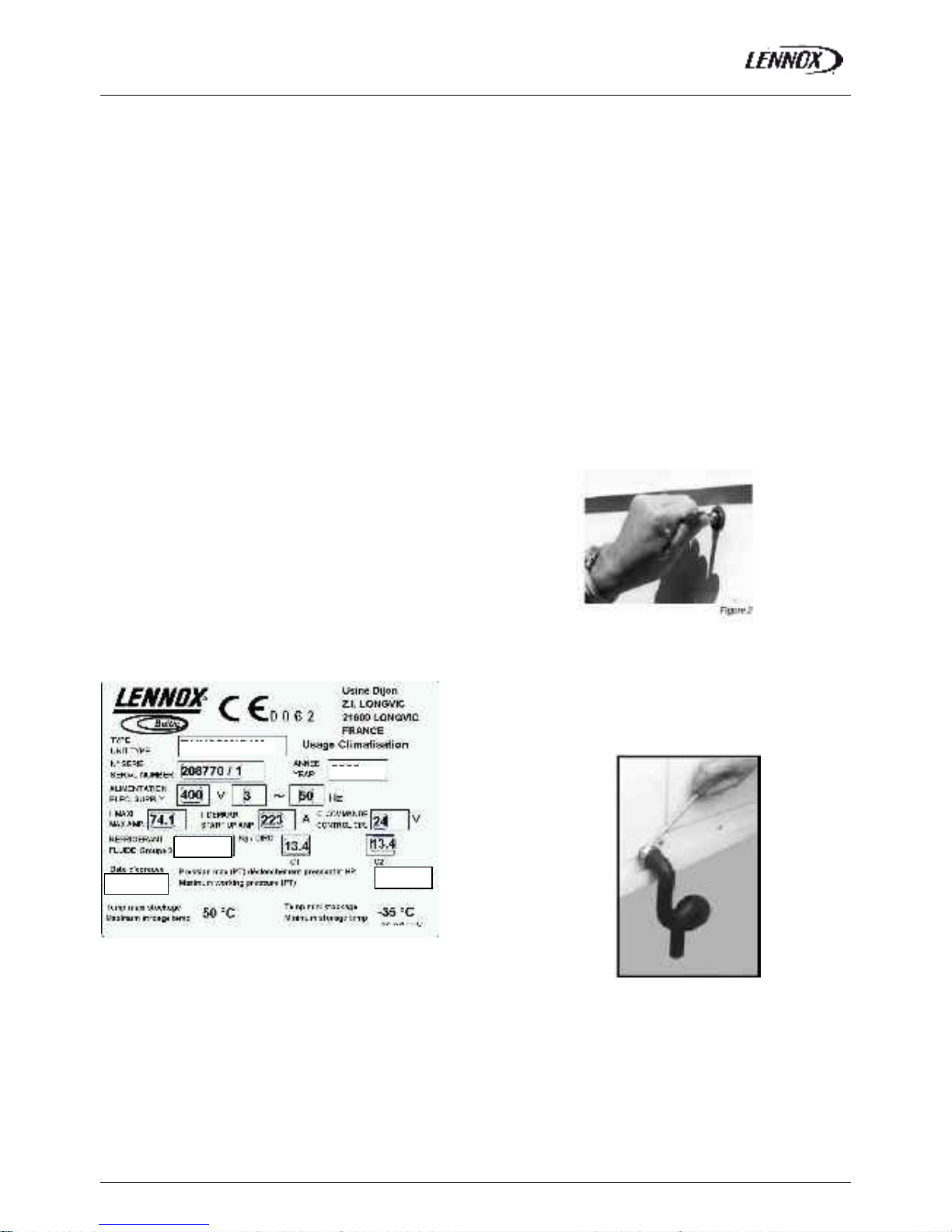
RATING PLATE
The rating plate provides a complete reference for the
model and ensures that the unit corresponds t o the model
ordered. It states the electrical power consumption of the
unit on start-up, its rated power and its supply voltage. The
supply voltage must not deviate beyond +10/-15 %. The
start-up power is the maximum value likely to be achieved
for the specified operational voltage. The customer must
have a suitable electrical supply. It is therefore important to
check whether the supply voltage stated on the unit's rating
plate is compatible with that of the mains electrical supply.
The rating plate also states the year of manufacture as well
as the type of refrigerant used and the required charge for
each compressor circuit.
Fig. 1
STORAGE
When units are delivered on site they are not always
required immediately and are sometimes put into storage.
In the event of medium to long-term storage, we
recommend the following procedures:
- Ensure that there is no water in the hydraulic systems.
- Keep the heat ex changer covers in position (A QUILUX cove r).
- Keep protective pl astic film in position.
- Ensure the electrical panels are closed.
- Keep all items and options supplied in a dry and clean
place for future assembly before using the equipment.
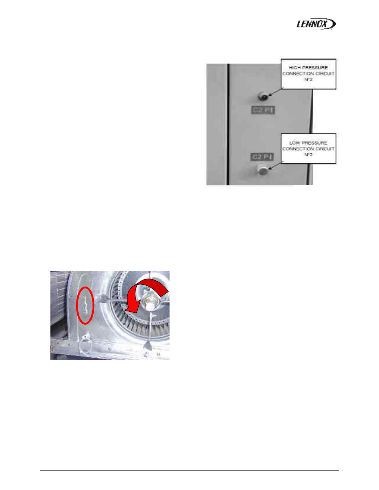
MAINTENANCE KEY
On delivery we recommend that you keep the key which is
attached to an eyebolt in a safe and accessible place. This
allows you to open the panels for maintenance and
installation work.
The locks are ¼ turn + then tighter (figure 2).
CONDENSATE DRAINS
The condensate drains are not assembled when delivered
and are stored
in the electrical panel with their clamping collars.
To assemble them, insert them on the condensate tray outlets
and use a screwdriver to tighten the collars (Figure 3).
Fig. 3
BAM055NM1M
2008
R410A
42.0 bar
18/05/2008
Page 13
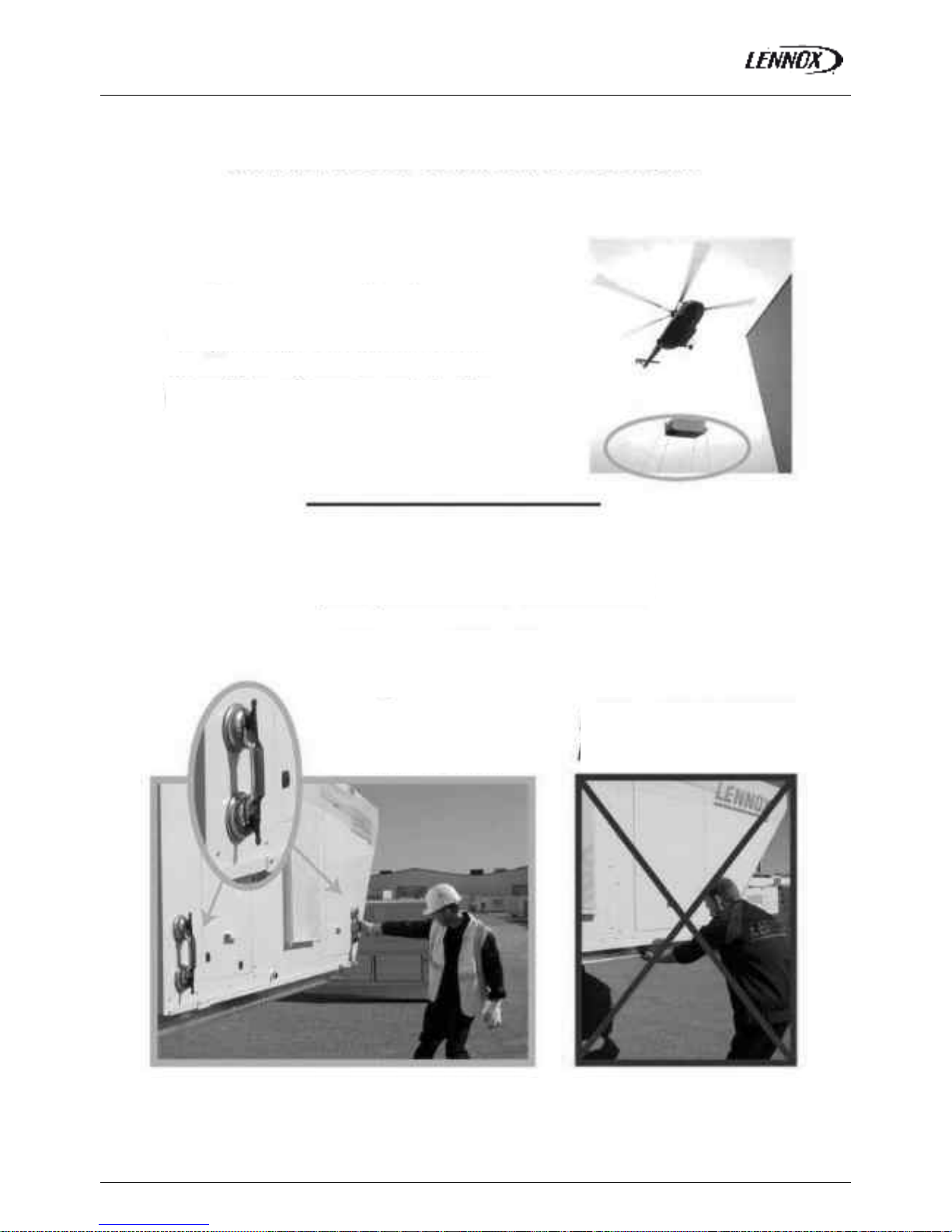
TRANSPORT – HANDLING - WARNING
BALTIC R410A-IOM-0708-E Page 12
Handling slings to guide the
unit towards the roofcurb
Vacuum lifting beam to
position the unit
COMPLIANT
NON
-
COMPLIANT
MANDATORY HANDLING DEVICES
Page 14
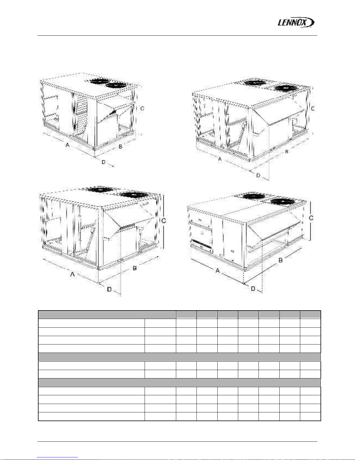
TRANSPORT – HANDLING
BALTIC R410A-IOM-0708-E Page 13
DIMENSIONS AND WEIGHTS
1
2
3
4
BALTIC™ BAC/BAH/BAG/BAM
20S 30S 35S 45S 55S 65D 75D
A mm
2017 2017 1890 1910 1910 2260 2260
B mm
1418 1418 1915 2235 2235 2873 2873
C mm
1220 1220 1221 1221 1221 1225 1225
D mm
484 484 414 418 418 418 418
Weight of standard units
Without hood
kg
394 414 547 604 619 796 852
With hood
kg
417 437 575 677 652 837 893
Poids des unités à gaz
Standard heat without hood
kg
445 465 608 678 693 904 960
Standard heat with hood
kg
468 488 636 711 726 945 1001
High heat without hood
kg
454 474 627 700 715 963 1019
High heat with hood
kg
477 497 655 733 748 1004 1060
Page 15
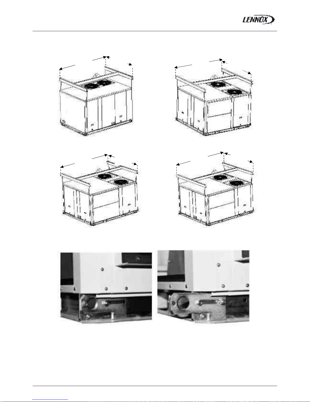
TRANSPORT – HANDLING
BALTIC R410A-IOM-0708-E Page 14
LIFTING THE UNITS
B box C box
D box E box
RETRACTABLE LIFTING LUG
Fig. 9
1850
(mini)
1410
(mini)
1930
(mini)
1700
(mini)
2250
(mini)
1700
(mini)
2890
(mini)
2080
(mini)
Fig. 5 Fig. 6
Fig. 7 Fig. 8
Page 16
TRANSPORT – HANDLING
BALTIC R410A-IOM-0708-E Page 15
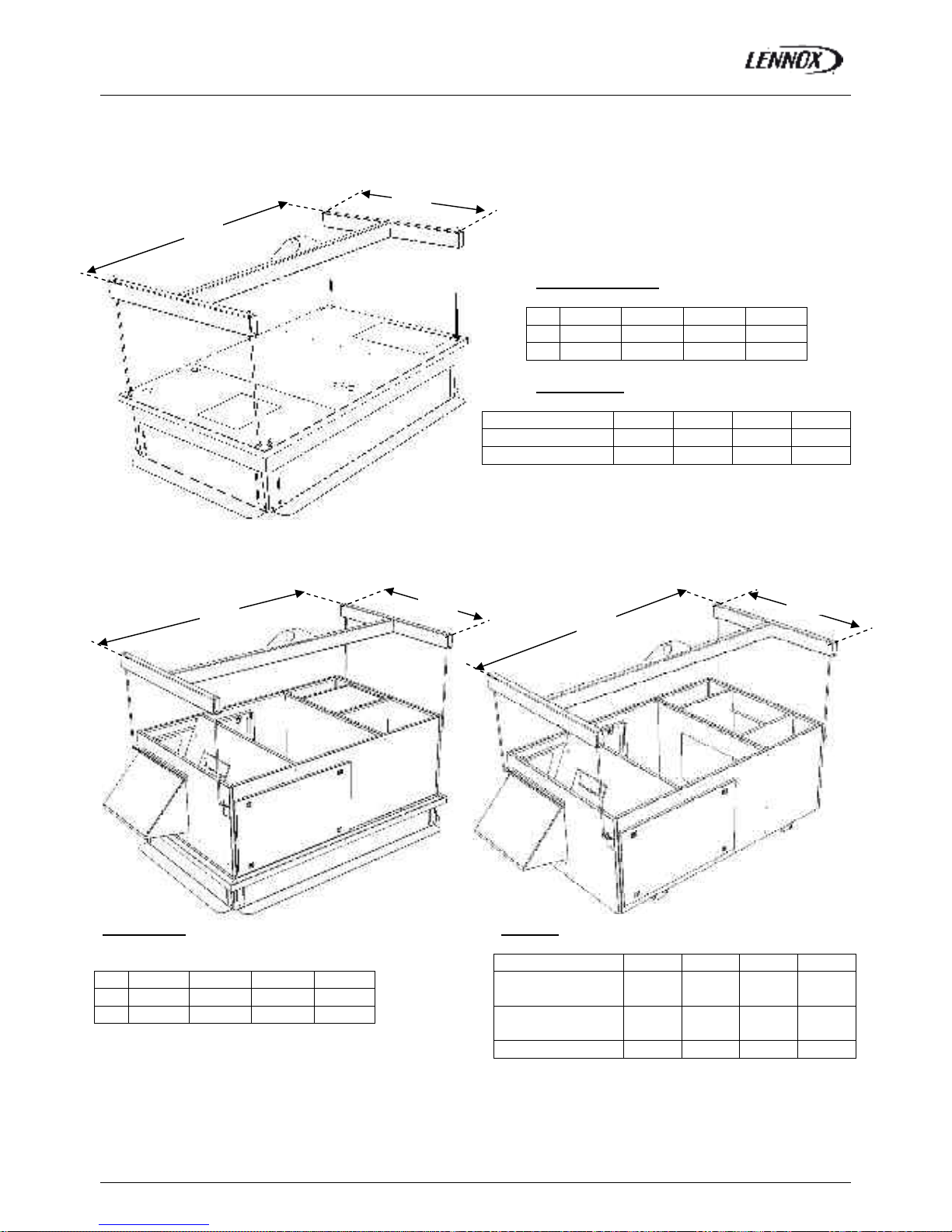
LIFTING THE ROOF CURBS
ADJUSTABLE ROOF CURB
Dimensions (mm)
B box C box D box E box
A 1890 1735 1735 2085
B 1100 1295 1545 1995
Weights (kg)
B box C box D box E box
No aux.heating 87 94 104 152
With aux.heating 86 90 100 138.2
EXHAUST ROOF CURB
Dimensions
B box C box D box E box
A 2050 1900 1900 2250
B 1160 1360 1610 2060
Weights
B box C box D box E box
Vertical No
aux.heating
192 220 240 370
Vertical With
aux.heating
194 194 240 365
Horizontal 142 168 185 301
Fig. 10
Fig. 11 Fig. 12
Page 17
TRANSPORT – HANDLING
BALTIC R410A-IOM-0708-E Page 16
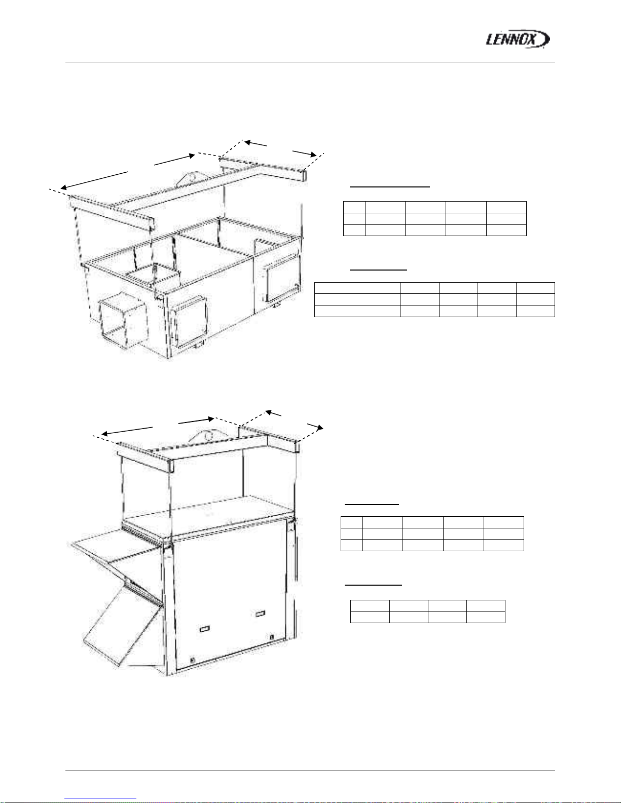
MULTIDIRECTIONNAL ROOF CURB
Dimensions (mm)
B box C box D box E box
A 2050 1900 1900 2250
B 1160 1360 1610 2060
Weights (kg)
B box C box D box E box
No aux.heating 81 88 100 147
With aux.heating 90 93 103 146.7
LIFTING THE ENERGY RECOVERY MODULE
Dimensions
B box C box D box E box
A 1290 1290 1290 1290
B 820 1170 1547 1895
Weights (kg)
B box C box D box E box
143 172 229 317
Fig.13
Fig.14
Page 18
INSTALLATION
BALTIC R410A-IOM-0708-E Page 17
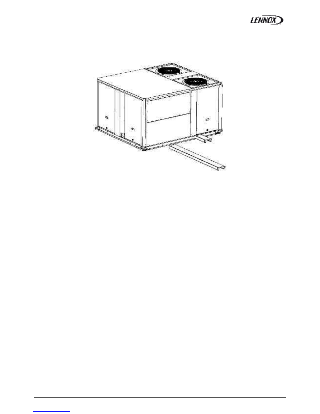
FORKLIFT PROTECTIONS
REMOVE THE FORKLIFT PROTECTIONS BEFORE INSTALLATION
PRELIMINARY CHECKS
Before installing the equipment, the following points MUST
be checked:
- Have the forklift protections been removed?
- Is there sufficient space for the equipment?
- Is the surface on which the equipment is to be
installed sufficiently solid to withstand its weight? A
detailed study of the frame must be made beforehand.
- Do the supply and return ductwork openings
excessively weaken the structure?
- Are there any obstructing items which could hinder the
operation of the equipment?
- Does the electrical power available correspond to the
equipment's electrical specifications?
- Is drainage provided for the condensate?
- Is there sufficient access for maintenance?
- Installation of the equipment could require different
lifting methods which may vary with each installation
(helicopter or crane). Have these been evaluated?
- Ensure that the unit is installed in accordance with the
installation instructions and local applicable codes.
- Check to ensure that the refrigerant lines do not rub
against the cabinet or against other refrigerant lines.
In general, make sure no obstacles (walls, trees or roof
ledges) are obstructing the duct connections or hindering
assembly and maintenance access.
INSTALLAT ION REQUIREMENTS
The surface on which the equipment is to be installed must
be clean and free of any obstacles which could hinder the
flow of air to the condensers:
-Avoid uneven surfaces
-Avoid installing two units side by side or close to each
other as this may restrict the airflow to the condensers.
Before installing a packaged Rooftop unit it is important to
understand:
- The direction of prevailing winds
-The direction and position of air flows.
-The external dimensions of the unit and the
dimensions
of the supply and return air connections.
-The arrangement of the doors and the space required
to open them to access the various components.
CONNECTIONS
-Ensure that all the pipe-work crossing walls or roofs
are secured, sealed and insulate d.
-To avoid condensation problems, make sure that all
pipes are insulated according to the temperatures of
fluids and type of rooms.
NOTE: The AQUILUX protection sheets fitted to the finned
surfaces must be removed prior to start up.
Fig. 15
Page 19
INSTALLATION
BALTIC R410A-IOM-0708-E Page 18
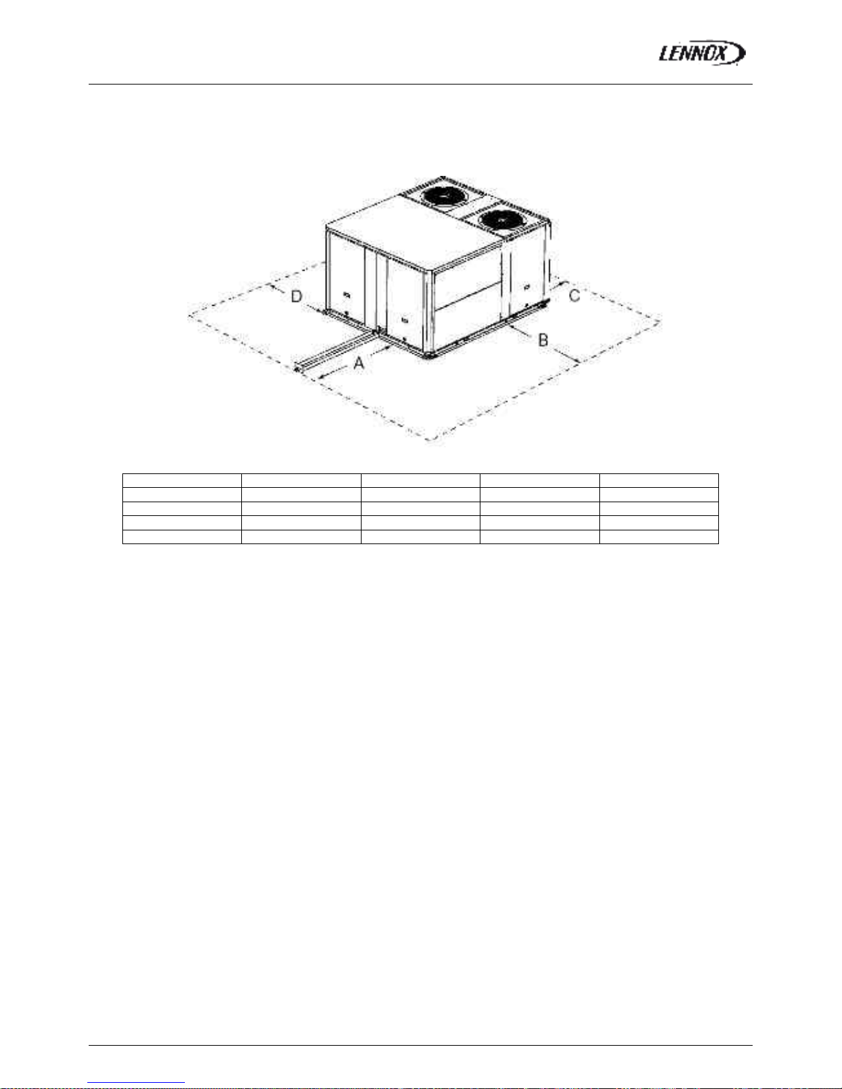
MINIMUM CLEARANCE AROUND THE UNIT
Figure 4 shows the required clearances and service access around the unit.
NOTE: Ensure the fresh air inlet does not face prevailing wind direction.
A B C D
B Box 1000
(1)
1500
(2)
1500 1000
C Box 1200
(1)
1500
(2)
1500 1000
D Box 1400
(1)
1500
(2)
1500 1000
E Box 1800
(1)
1500
(2)
1500 1100
(1) Add 1 meter if the units are equipped with gas burner
(2) Double this distance if the units are equipped with extraction
Fig. 16
Page 20
INSTALLATION ON A ROOF MOUNTING FRAMES
BALTIC R410A-IOM-0708-E Page 19
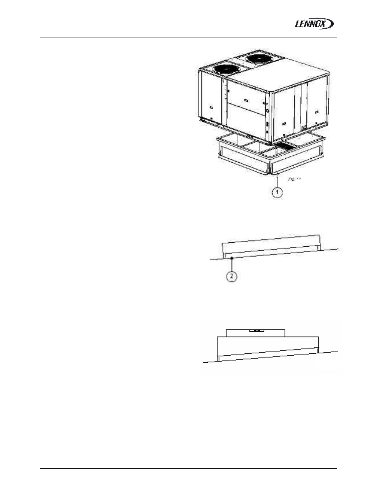
POSITIONING ROOFCURBS
As levels are adjustable, observe the following
recommendations when installing the equipment.
Above all, ensure that all the adjustable returns are facing
outward (“1” figure 17). They are usually turned inside-out
for transport.
Place the roof mounting frame on the trimmer beam by first
lining up the inlet and the outlet opening. (“2”- figure 18)
After levelling the frame, secure the adjustable returns on
the trimmer.
It is important to centre the unit on the roof frame.
Fig. 17
Fig. 18
Fig. 19
Page 21
INSTALLATION ON A ROOF MOUNTING FRAMES
BALTIC R410A-IOM-0708-E Page 20
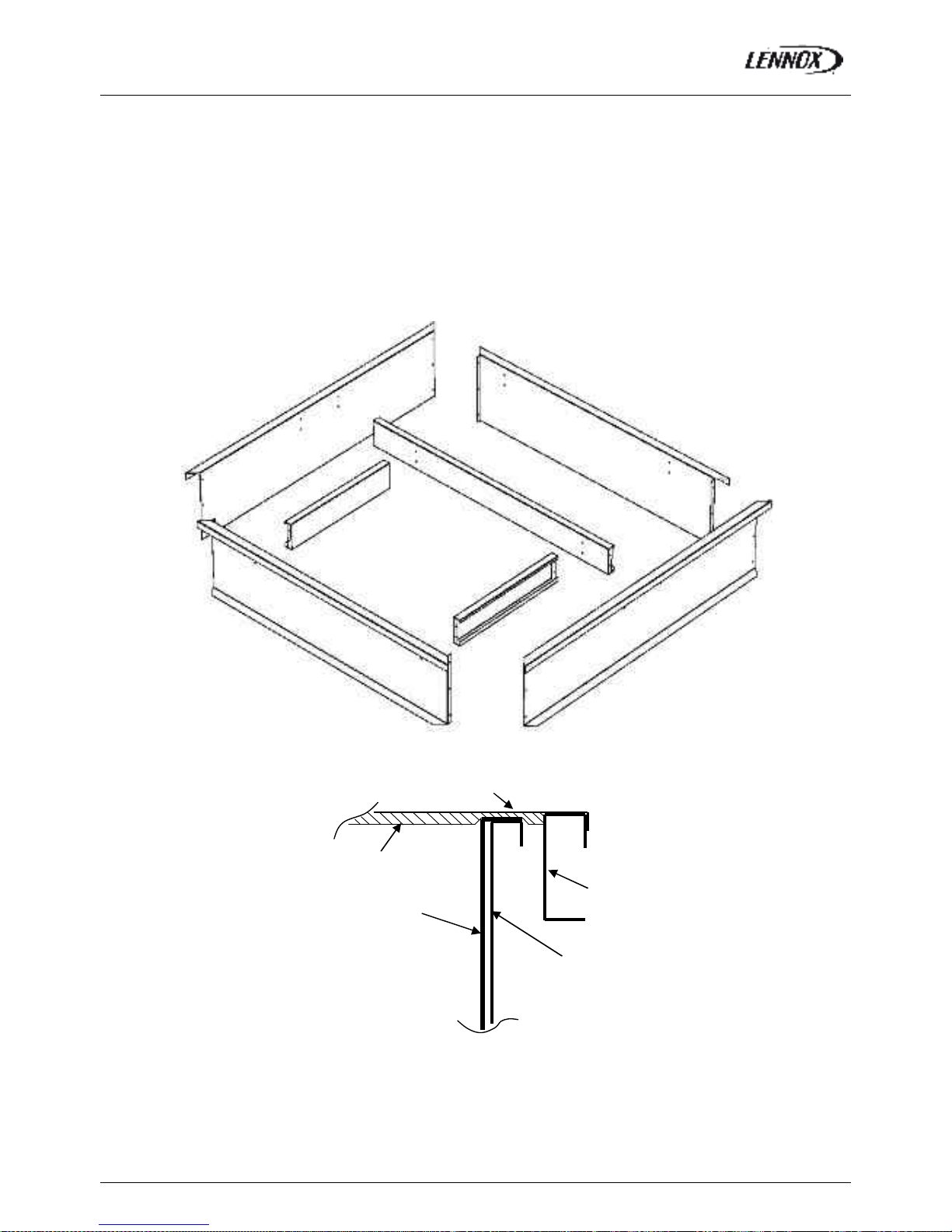
NON ADJUSTABLE NON ASSEMBLIED ROOFCURB
FRAME PARTS IDENTIFICATION
Figure 20 shows the different parts used in the assembly of this roof mounting frame.
INSTALLATION
The roof mounting frame provides support when the units are installed in down-flow configurations.
The non adjustable, non assembled roof mounting frame can be installed directly on decks having adequate structural strength
or on roof supports under deck. See page 24 for frame dimensions, location of supply and return air opening
NOTE: frame assembly must be installed flat, levelled within 5mm per linear meter in any direction.
UNIT FLOOR
UNIT FLOOR
AIR DUCT
UNIT Support rail
ROOFCURB
Fig. 20
Fig. 21
Page 22
INSTALLATION ON A ROOF MOUNTING FRAMES
BALTIC R410A-IOM-0708-E Page 21
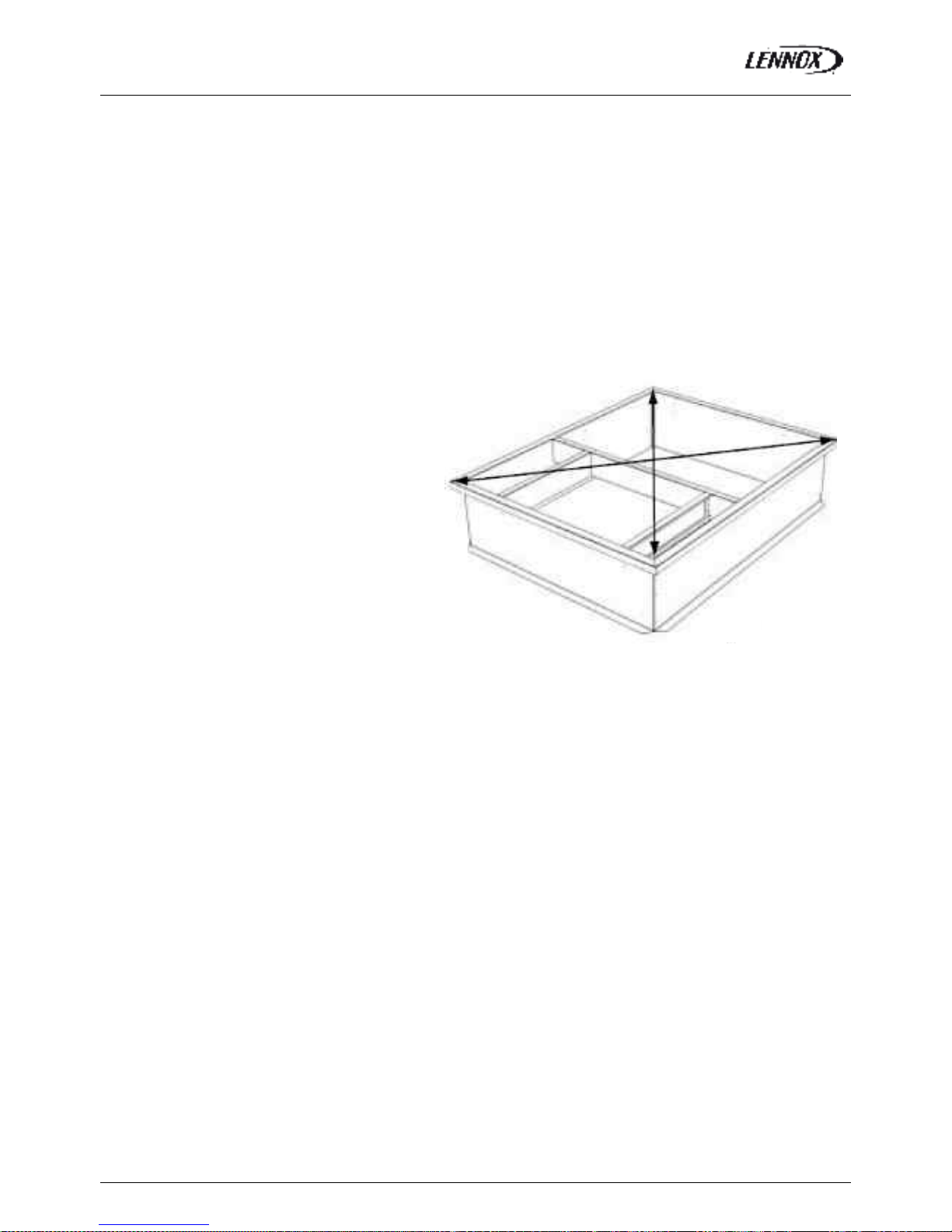
NON ADJUSTABLE NON ASSEMBLED ROOFCURB
ASSEMBLY
The frame is supplied as a single package and shipped folded down for ease of transport and handling. It is easy field
assembled as all parts required are supplied with the frame.
SECURING THE FRAME
To ensure proper mating with units (figure 22), it is mandatory that the roof mounting frame be squared to roof structure as
follows:
-With frame positioned levelled in the desired location
on roof trusses, tack weld corne r of frame.
-Measure frame diagonally from corner to corner as
shown in figure 16. These Dimensions must be equal in
order for the fame to be square.
-It is extremely important to sight frame from all corner
to ensure it is not twisted across. Shim frame under any
low side. The maximum slope tolerance is 5mm per
linear meter in any direction.
-After the frame has been squared, straightened and
shimmed, weld or secure the frame to the roof deck.
NOTE: It must be securely fastened to the roof as per local codes and regulations.
Fig. 22
Page 23
INSTALLATION ON A ROOF MOUNTING FRAMES
BALTIC R410A-IOM-0708-E Page 22
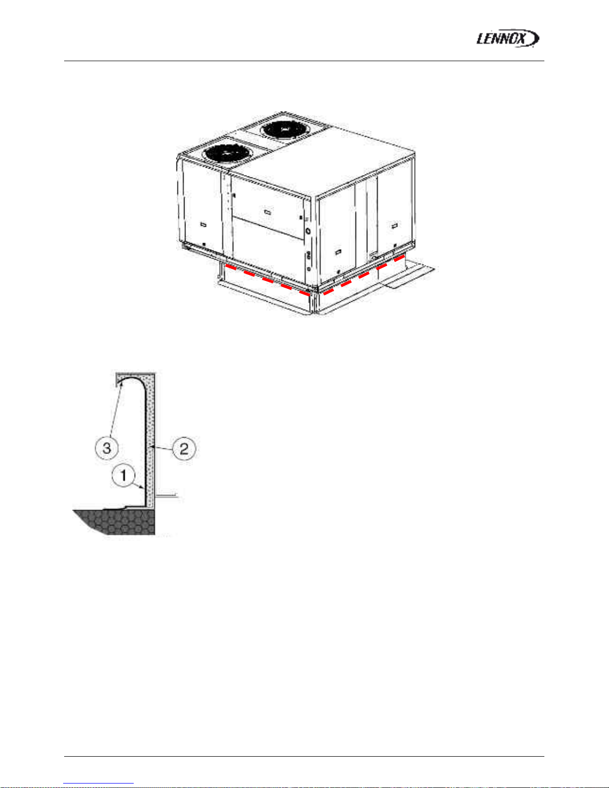
SECURING THE CURB
When the frame is correctly positioned, it is essential to secure the assembly with a disconnected stitched welded seam (20 to
30 mm every 200 mm
- - - -) along the outside or by using an alternative method.
CURBING AND FLASHING
Outside of frame must be insulated with rigid type insulation;
We recommend a minimum of 20 mm thick insulation (2 figure 24).
Check that the insulation is continuous, counter flash and seal around the frame
as shown in (1-figure 24).
CAUTION: To be effective, the upstream must end below the drop edge (3 - figure
24).
Where pipes and electrical conduits extend through the roof, flashing must
conform to local codes of practice
Before installing the equipment, make sure that seals are not damaged and check that the unit is secured to the mounting
frame. Once in position, the bottom of the equipment must be horizontal.
The installer must comply with local authority standards and specifications.
Fig. 23
Fig. 24
Page 24

INSTALLATION ON A ROOF MOUNTING FRAMES
BALTIC R410A-IOM-0708-E Page 23
Heat Recovery Installation
1) The unit being already erected on the roof curb, position the elbow by plugging the returns (A) in the slits (B) of the
framework of the unit: see detail
2) Fix the elbow with caged nuts at envisaged places (C)
3) Apply mastic on the two side studs and on the superior stud of the energy recovery box.
4) Pose the energy recovery box on the elbow
5) Fix the energy recovery box thanks to the two edges at 45° right and left with self-drilling screws (D)
1
4
Fig. 25
Page 25
ECONOMISER AND EXTRACTION
BALTIC R410A-IOM-0708-E Page 24
Economiser
Free cooling can be provided through the use of fresh air where appropriate rather than
cooling excessive amounts of return air.
The economiser is factory fitted and tested prior to shipment.
It includes two dampers operating from a 24V actuator
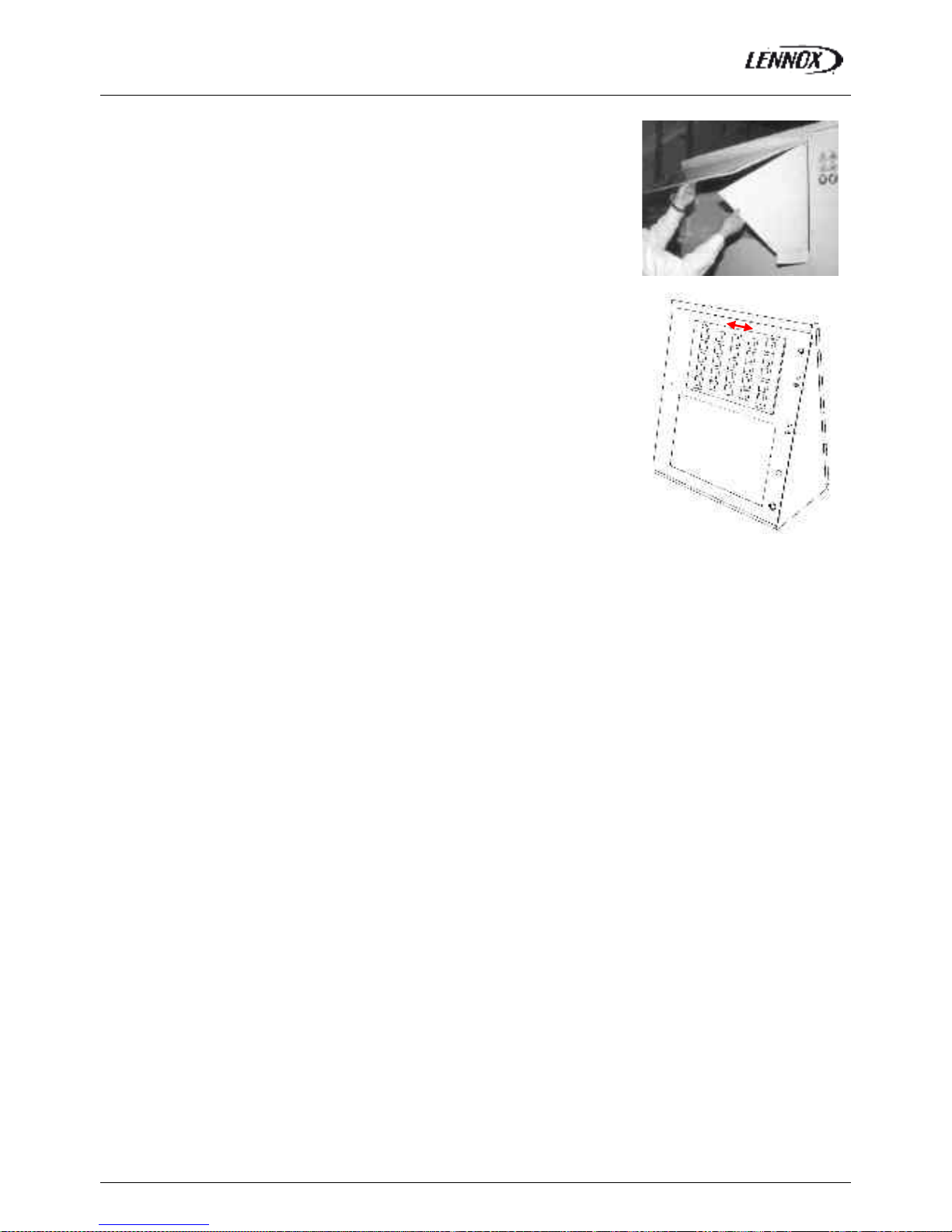
Rain hood
It also includes a factory fitted rai n hood. Hoods is folded during transportation to limit
risks of damage and must be unfolded on site as shown on fig. 26
Extraction
Installed with economiser assembly, the gravity exhaust dampers relieve the pressure
when outside air is introduced into the system.
When large amount of fresh air is introduced into the system power exhaust fans can be
used to equalise the pressures.
The extraction fan runs when return air dampers are being closed and supply air blower is
in operation. The extraction fan runs when outdoor air dampers are at least 50% open
(adjustable value). It is overload protected.
NOTE: When horizontal flow configuration is required, the multidirectional roof curb will be
installed.
0-25% fresh air manual (Fig. 27)
It is enough to loosen the mobile grid's screws and to make it slip.
0%: screw into limit stop on the right
25%: screw into limit stop on the left
Fig. 27
Fig. 26
Page 26
ECONOMISER AND EXTRACTION
BALTIC R410A-IOM-0708-E Page 25
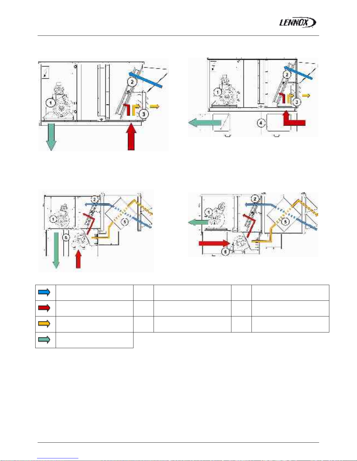
VERTICAL FLOW
ENERGY RECOVERY MODULE + EXHAUST
ROOFCURB
(Vertical flow)
MULTIDIRECTIONAL ROOFCURB
ENERGY RECOVERY MODULE + EXHAUST
ROOFCURB
(Horizontal flow)
Fresh air 1 Supply fan 4 Multidirectional roofcurb
Return air 2 Economiser damper 5 Heat recovery module
Exhaust air 3 Exhaust damper 6 Exhaust Roofcurb
Supply air
Page 27

COMMISSIONING
BALTIC R410A-IOM-0708-E Page 26
THIS WORK MUST ONLY BE CARRIED OUT
BY TRAINED REFRIGERATION ENGINEERS
FILL THE COMMISSI ONNING SHEET AS YOU GO
ALONG
ELECTRICAL CONNECTIONS
Ensure that the power supply between the building and the
unit meets local authority standards and that the cable
specification satisfies the start-up and operating conditions.
ENSURE THAT THE POWER SUPPLY
INCLUDES 3 PHASES
(+ NEUTRAL if the unit is equipped with the
power exhaust fan)
Check the following wire connections for tightness:
Main switch connections, mains wires linked to the
contactors and circuit breakers and the cables in the
24V control supply circuit.
How to connect roof curbs and energy recovery module
Cables and their connectors corresponding to the roof curb’
motor and actuator and extraction box’ ones are already
rolled up in these elements; it is enough to bring them
through the openings envisaged and to connect them on
the sites indicated on the figure 28.
It’s the same procedure when you have an energy recovery
module.
PRELIMINARY CHECKS
Ensure that all drive motors are secure.
Ensure that the adjustable pulley blocks are secure and
that the belt is tensioned with the transmission correctly
aligned. Refer to the next section foe details.
Using the electrical wiring diagram, check the
conformity of the electrical safety devices (circuit
breaker settings, presence and rating of fuses).
Check the temperature probe connections.
Fig.29
Connector for the roof
curb motor or the
extraction box’ one
Connector for the roof
curb actuator or the
extraction box’ one
Connector for the
energy recovery
module + Fresh air
sensor
Fig. 28
Page 28

COMMISSIONING
BALTIC R410A-IOM-0708-E Page 27
STARTING THE UNIT
At this point the unit circuit breakers should be open
You will need a DS50 maintenance controller or Climalook
with appropriate Interface.
Fig. 30
The jumpers are factory set and the configuration switches
are adjusted depending on the op tion the type of unit.
Connecting the CLIMATIC displays
Fig. 31
Close the 24V Control Circuit breakers.
Fig. 32
The CLIMATIC 50 starts after 30s
Reset the DAD photo (If fitted)
Fig. 33
Check and adjust the control settings.
Refer to the control section in this manual to adjust the
different parameters
Language o r
ENGLISH
RT 050.001
BIOS. 0000 Boot 0000
Page 29
COMMISSIONING
BALTIC R410A-IOM-0708-E Page 28
POWERING THE UNIT
- Power up the unit by closing the isolator switch (if fitted).
- At this point the blower should start unless the climatic
does not energise the contactor. In this particular case
the blower can be forced by bridging the port NO7 and
C7 on connector J14 on the Climatic. Once the fan is
running, check the rotation direction. Refer to the rotation
arrow located on the fan.
- The fans and compressors direction of rotation is
checked during the end of line test. They should therefore
all turn in either the right or wrong direction.
NOTE: A compressor rotating in the wrong direction will
fail.
- If the fan turns in the wrong direction (the right direction
is shown on figure n° 27), disconnect the main power
supply to the machine at the building's mains switch,
reverse two phases and repeat the above procedure.
- Close all circuit breakers and power up the unit, remove
the bridge on connector J14 if fitted.
- If now only one of the components rotates in the wrong
direction, disconnect the power supply at the machine's
isolator switch (if fitted) and reverse two of the
component’s phases on the terminal within the electrical
panel.
- Check the current drawn against the rated values, in
particular on the supply fan (ref. page 34).
- If the readings on the fan are outside the specified
limits, this usually indicates excessive air flow which will
affect the life expectancy and the thermodynamic
performances of the unit. This will also increase the risks
of water ingress into the unit. Refer to the "Air Flow
Balancing" section to correct the problem.
At this point attach the manometers to the refrigerant circuit
Fig. 34
RUN TEST
Start unit in cooling mode
Thermodynamic readings using manometers and prevailing
environmental conditions
No rated values are given here. These depend on the
climatic conditions both outside and inside the building
during operation. However, an experienced refrigeration
engineer will be able to detect any abnormal machine
operation.
Safety test
- Check Air pressure switch (if fitted) "Dirty filter" detection
test: vary the set-point value (menu page 3413 on DS50)
in respect to the air pressure value. Observe the response
of the CLIMATIC™.
- Same procedure for detecting "Missing Filter" (page
menu 3412) or "Air Flow Detection" (page menu 3411).
- Check the smoke detection function (if fitted).
- Check the Firestart by press ing the test button (if fitted).
- Disconnect the circuit breakers of the capacitor fans and
check the high pressure cut-out points on different
refrigerant circuits.
Reverse cycle test
This test is designed to check the good operation of the 4way reversing valves on heat pump reversible systems.
Start the reverse cycle by adjusting the cold or hot
temperature threshold data according to the i ndoor and
outdoor conditions at the time of te st (menu 3320)
Fig. 35
Page 30
ARRANGEMENT DRAWINGS
BALTIC R410A-IOM-0708-E Page 29
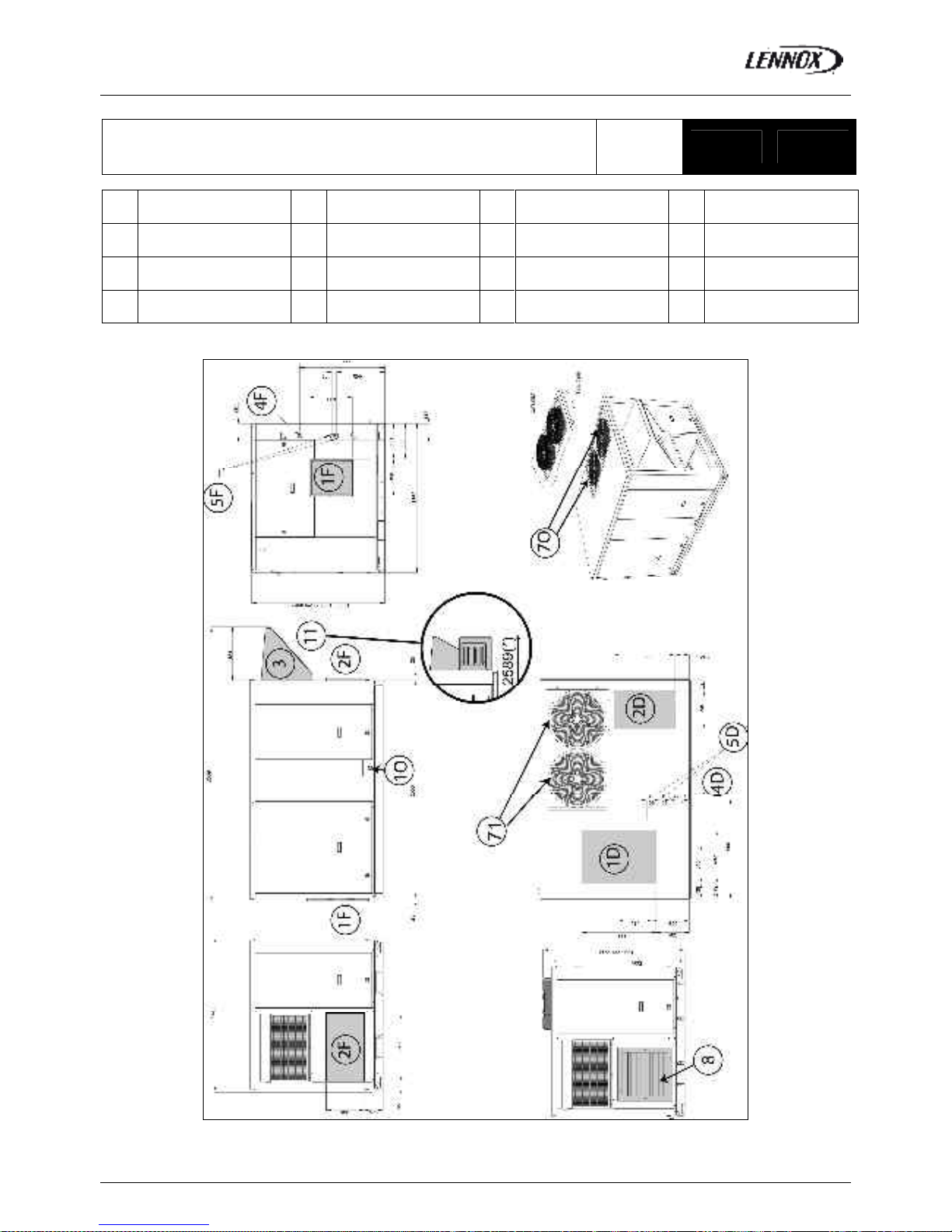
WITH OPTIONS
(Return and supply opening shown on this drawing do not apply to
BAC/BAH with electric heater or hot water coil )
BAC
BAH
020 030
1D Down supply air 3 Fresh air 5D Down hot water entry 8 Extraction
1F Front supply air 4F Front main power entry 9 Smoke outlet
2D Down return air 4D
Down main power
entry
71 Outdoor coil inlet 10 Condensate drainage
2F Front return air 5F Front hot water entry 70 Outdoor coil outlet
(*) Total Length (unit + option)
Page 31

ARRANGEMENT DRAWINGS
BALTIC R410A-IOM-0708-E Page 30
WITH OPTIONS
(Return and supply opening shown on this drawing do apply to BAC/BAH
with electric heater or hot water coil )
BAG
BAM
020 030
1D Down supply air 3 Fresh air 8 Extraction
1F Front supply air 4F Front main power entry 6 Gas supply inlet 9 Smoke outlet
2D Down return air 4D
Down main power
entry
71 Outdoor coil inlet 10 Condensate drainage
2F Front return air 70 Outdoor coil outlet
(*) Total Length (unit + option)
Page 32

ARRANGEMENT DRAWINGS
BALTIC R410A-IOM-0708-E Page 31
WITH OPTIONS
(Return and supply opening shown on this drawing do not apply to BAC/BAH with electric
heater or hot water coil )
BAC
BAH
035
1D Down supply air 3 Fresh air 5D Down hot water entry 8 Extraction
1F Front supply air 4F Front main power entry 9 Smoke outlet
2D Down return air 4D
Down main power
entry
71 Outdoor coil inlet 10 Condensate drainage
2F Front return air 5F Front hot water entry 70 Outdoor coil outlet
(*) Total Length (unit + option)
Page 33

ARRANGEMENT DRAWINGS
BALTIC R410A-IOM-0708-E Page 32
WITH OPTIONS
(Return and supply opening shown on this drawing do apply to BAC/BAH with electric
heater or hot water coil )
BAG
BAM
035
1D Down supply air 3 Fresh air 8 Extraction
1F Front supply air 4F Front main power entry 6 Gas supply inlet 9 Smoke outlet
2D Down return air 4D
Down main power
entry
71 Outdoor coil inlet 10 Condensate drainage
2F Front return air 70 Outdoor coil outlet
(*) Total Length (unit + option)
Page 34

ARRANGEMENT DRAWINGS
BALTIC R410A-IOM-0708-E Page 33
WITH OPTIONS
(Return and supply opening shown on this drawing do not apply to
BAC/BAH with electric heater or hot water coil )
BAC
BAH
045 055
1D Down supply air 3 Fresh air 5D Down hot water entry 8 Extraction
1F Front supply air 4F Front main power entry 9 Smoke outlet
2D Down return air 4D
Down main power
entry
71 Outdoor coil inlet 10 Condensate drainage
2F Front return air 5F Front hot water entry 70 Outdoor coil outlet
(*) Total Length (unit + option)
Page 35

ARRANGEMENT DRAWINGS
BALTIC R410A-IOM-0708-E Page 34
WITH OPTIONS
(Return and supply opening shown on this drawing do apply to BAC/BAH
with electric heater or hot water coil )
BAG
BAM
045 055
1D Down supply air 3 Fresh air 8 Extraction
1F Front supply air 4F Front main power entry 6 Gas supply inlet 9 Smoke outlet
2D Down return air 4D
Down main power
entry
71 Outdoor coil inlet 10 Condensate drainage
2F Front return air 70 Outdoor coil outlet
(*) Total Length (unit + option)
Page 36

ARRANGEMENT DRAWINGS
BALTIC R410A-IOM-0708-E Page 35
WITH OPTIONS
(Return and supply opening shown on this drawing do not apply to
BAC/BAH with electric heater or hot water coil )
BAC
BAH
065 075
1D Down supply air 3 Fresh air 5D Down hot water entry 8 Extraction
1F Front supply air 4F Front main power entry 9 Smoke outlet
2D Down return air 4D
Down main power
entry
71 Outdoor coil inlet 10 Condensate drainage
2F Front return air 5F Front hot water entry 70 Outdoor coil outlet
(*) Total Length (unit + option)
Page 37

ARRANGEMENT DRAWINGS
BALTIC R410A-IOM-0708-E Page 36
WITH OPTIONS
(Return and supply opening shown on this drawing do apply to BAC/BAH
with electric heater or hot water coil )
BAG
BAM
065 075
1D Down supply air 3 Fresh air 8 Extraction
1F Front supply air 4F Front main power entry 6 Gas supply inlet 9 Smoke outlet
2D Down return air 4D
Down main power
entry
71 Outdoor coil inlet 10 Condensate drainage
2F Front return air 70 Outdoor coil outlet
(*) Total Length (unit + option)
Page 38

NON ADJUSTABLE ROOFCURB
BALTIC R410A-IOM-0708-E Page 37
BAC = Cooling only unit
BAH = Heat pump unit
BAG = Cooling only unit with gas fired heating
BAM = Heat pump unit with gas fired heating
ALL UNITS
1D Down supply air 8 Main Power Entry 030-035-040-045-050
2D Return air 8’ Main Power Entry 020-025
Type Size A B C D E F G H I J
020
030
1183 1893 691 400 246 246 515 50 1783 1083
035 1380 1740 790 400 351 240 675 50 1640 1280
045
055
1630 1740 1050 400 352 229 675 50 1640 1530
065
All
075
2080 2090 1400 400 425 255 720 156 1990 1980
Roof opening I x J
Page 39

ADJUSTABLE ROOFCURB
BALTIC R410A-IOM-0708-E Page 38
020 030
A B
BAC / BAH _BAG / BAM or BAC / BAH with auxiliary heating 247 691
1D Down supply air 4D Down main power entry
2D Down return air 5D Down hot water entry
8 Main power entry
Roof opening 1795 x 1085
Page 40

ADJUSTABLE ROOFCURB
BALTIC R410A-IOM-0708-E Page 39
035
A B C D
BAC / BAH _BAG / BAM or BAC / BAH with auxiliary heating 636 351 790 241
1D Down supply air 4D Down main power entry
2D Down return air 5D Down hot water entry
8 Main power entry
Roof opening 1642 x 1282
Page 41

ADJUSTABLE ROOFCURB
BALTIC R410A-IOM-0708-E Page 40
045 055
A B C D
BAC / BAH _ BAG / BAM or BAC / BAH with auxiliary heating 352 1050 230 637
1D Down supply air 4D Down main power entry
2D Down return air 5D Down hot water entry
8 Main power entry
Roof opening 1642 x 1532
Page 42

ADJUSTABLE ROOFCURB
BALTIC R410A-IOM-0708-E Page 41
BAC
BAH
BAG
BAM
065 075
1D Down supply air 4D Down main power entry
2D Down return air 5D Down hot water entry
8 Main power entry
Page 43

MULTIDIRECTIONAL HORIZONTAL ROOFCURB
BALTIC R410A-IOM-0708-E Page 42
BAC
BAH
BAG
BAM
020 030
1F 2F
1F’
Front supply air
2F’
Front return air
(*) This roofcurb is also necessary for all cooling only or heatpump rooftop with auxiliary electric heater or hot water coil.
WARNING : ONLY ONE OF THE 4 FOLLOW INGS POSSIBILITIES :
2F - 1F / 2F - 1F'
2F' - 1F / 2F' - 1F'
Page 44

MULTIDIRECTIONAL HORIZONTAL ROOFCURB
BALTIC R410A-IOM-0708-E Page 43
BAC
BAH
BAG
BAM
035
1F 2F
1F’
Front supply air
2F’
Front return air
(*) This roofcurb is also necessary for all cooling only or heatpump rooftop with auxiliary electric heater or hot water coil.
WARNING : ONLY ONE OF THE 4 FOLLOW INGS POSSIBILITIES :
2F - 1F / 2F - 1F'
2F' - 1F / 2F' - 1F'
Page 45

MULTIDIRECTIONAL HORIZONTAL ROOFCURB
BALTIC R410A-IOM-0708-E Page 44
BAC
BAH
BAG
BAM
045 055
1F 2F
1F’
Front supply air
2F’
Front return air
(*) This roofcurb is also necessary for all cooling only or heatpump rooftop with auxiliary electric heater or hot water coil.
WARNING : ONLY ONE OF THE 4 FOLLOW INGS POSSIBILITIES :
2F - 1F / 2F - 1F'
2F' - 1F / 2F' - 1F'
Page 46

MULTIDIRECTIONAL HORIZONTAL ROOFCURB
BALTIC R410A-IOM-0708-E Page 45
BAC
BAH
BAG
BAM
065 075
1F 2F
1F’
Front supply air
2F’
Front return air
WARNING : ONLY ONE OF THE 4 FOLLOW INGS POSSIBILITIES :
2F - 1F / 2F - 1F'
2F' - 1F / 2F' - 1F'
Page 47

EXHAUST VERTICAL ROOFCURB
BALTIC R410A-IOM-0708-E Page 46
020 030
A B
BAC / BAH without auxiliary heating 395 542
BAG / BAM or BAC / BAH with auxiliary heating 691 246
1D Down supply air 4D Down main power entry
2D Down return air 5D Down hot water entry
8 Main power entry 9 Exhaust
Page 48

EXHAUST VERTICAL ROOFCURB
BALTIC R410A-IOM-0708-E Page 47
035
A B C
BAC / BAH without auxiliary heating 632 400 348
BAG / BAM or BAC / BAH with auxiliary heating 350 790 240
1D Down supply air 4D Down main power entry
2D Down return air 5D Down hot water entry
8 Main power entry 9 Exhaust
Page 49

EXHAUST VERTICAL ROOFCURB
BALTIC R410A-IOM-0708-E Page 48
045 055
A B B C
BAC / BAH without auxiliary heating 749 500 382 496
BAG / BAM or BAC / BAH with auxiliary heating 351 1050 229 636
1D Down supply air 4D Down main power entry
2D Down return air 5D Down hot water entry
8 Main power entry 9 Exhaust
Page 50

EXHAUST VERTICAL ROOFCURB
BALTIC R410A-IOM-0708-E Page 49
BAC
BAH
BAG
BAM
065 075
1D Down supply air 4D Down main power entry
2D Down return air 5D Down hot water entry
8 Main power entry 9 Exhaust
Page 51

EXHAUST HORIZONTAL ROOFCURB
BALTIC R410A-IOM-0708-E Page 50
BAC
BAH
BAG
BAM
020 030 035
1D Down supply air 4D Down main power entry
2D Down return air 5D Down hot water entry
8 Main power entry 9 Exhaust
Page 52

EXHAUST HORIZONTAL ROOFCURB
BALTIC R410A-IOM-0708-E Page 51
BAC
BAH
BAG
BAM
045 055
1D Down supply air 4D Down main power entry
2D Down return air 5D Down hot water entry
8 Main power entry 9 Exhaust
Page 53

EXHAUST HORIZONTAL ROOFCURB
BALTIC R410A-IOM-0708-E Page 52
BAC
BAH
BAG
BAM
065 075
1D Down supply air 4D Down main power entry
2D Down return air 5D Down hot water entry
8 Main power entry 9 Exhaust
Page 54

TRANSITION ROOFCURB
BALTIC R410A-IOM-0708-E Page 53
BAC
BAH
BAG
BAM
065 075
1D Down supply air 4D Down main power entry
2D Down return air 5D Down hot water entry
8 Main power entry 9 Exhaust
Page 55

ENERGY RECOVERY OPTION
BALTIC R410A-IOM-0708-E Page 54
020 030
Part 1 and 2 are supplied loose + Fresh air and extracted air hood closed
Exhaust air
Fresh air
Exhaust air
Fresh air
Page 56

ENERGY RECOVERY OPTION
BALTIC R410A-IOM-0708-E Page 55
035
Part 1 and 2 are supplied loose + Fresh air and extracted air hood closed
Exhaust air
Fresh air
Exhaust air
Fresh air
Page 57

ENERGY RECOVERY OPTION
BALTIC R410A-IOM-0708-E Page 56
045 055
Part 1 and 2 are supplied loose + Fresh air and extracted air hood closed
Exhaust air
Fresh air
Exhaust air
Fresh air
Page 58

ENERGY RECOVERY OPTION
BALTIC R410A-IOM-0708-E Page 57
065 075
Part 1 and 2 are supplied loose + Fresh air and extracted air hood closed
Exhaust air
Fresh air
Exhaust air
Fresh air
Page 59

VENTILATION BELT TENSION
BALTIC R410A-IOM-0708-E Page 58
BELT TENSION
On delivery, the drive belts are new and correctly
tensioned. After the first 50 operating hours check and
adjust the tension. 80% of the total elongation of belts is
generally produced during the first 15 hours of operation.
Before adjusting the tension, make sure that the pulleys are
correctly aligned.
To tension the belt, set the height of motor support plate by
moving the plate adjustment screws.
The recommended deflection is 20 mm per metre from
centre to centre.
Check that according to the diagram below (figure 37), the
following ratio rem ains the same.
A (mm)
= 20
P (mm)
The belts should always be replaced when:
- The disk is set to maximum,
- The belt rubber is worn or the wire is visible.
Replacement belts must have the same rated size as the
ones they are replacing. If a transmission system has
several belts, they must all be from the same
manufacturing batch (compare serial numbers).
Fig.36
NOTE:
An under-tensioned belt will slip, heat and wear
prematurely. On the other hand, if a belt is over-tensioned,
the pressure on the bearings will cause them to over-heat
and wear prematurely. Incorrect alignment will also cause
the belts to wear prematurely.
Fig. 37
Page 60

VENTILATION : PULLEYS
BALTIC R410A-IOM-0708-E Page 59
MOUNTING AND ADJUSTING PULLEYS
Fan pulley removal
Remove the 2 screws and put one of them in the extraction
threaded screw.
Screw in fully. The hub and the pulley will separate from
each other.
Remove the hub and the pulley by hand without damaging
the machine.
Fig. 38
Fan pulley installation
Clean and de-grease the shaft, hub and conical bore of the
pulley. Lubricate the screws and install the hub and pulley.
Position the screws without turning them.
Place the assembly on the shaft and screw in the screws
alternatively and evenly. Using a mallet or a hammer with a
wooden wedge, tap on the face of the hub to keep the
assembly in place. Torque the screws to 30 Nm.
Take the pulley in both hands and shake it vigorously to
make sure everything is in place.
Fill the holes with grease for protection.
NOTE : During installation, the key should never protrude
out of its groove.
After 50 operating hours, check that the screws are still in
place.
Fig.39
MOTOR PULLEY INSTALLATION AND REMOVAL
The pulley is held in position by the key and a screw
located in the groove. After unlocking, removing this screw
by pulling against the shaft spindle (if necessary, use a
mallet and tap uniformly on the hub to remove it).
To assemble, proceed in the reverse order after having
cleaned and de-greased the motor shaft and the pulley
bore.
PULLEYS ALIGNMENT
After adjusting one or both of the pulleys, check the
transmission alignment using a ruler placed on the inner
face of the two pulleys.
NOTE: The warranty may be affected if any major
modification is made to the
transmission without obtaining our agreement beforehand.
Fig. 40
Page 61

VENTILATION: AIRFLOW BALANCING
BALTIC R410A-IOM-0708-E Page 60
The actual resistance of ductwork systems is not always identical to the calculated theoretical values. To rectify this, it may be
necessary to modify the pulley and be lt setting. To this effect, the motors are fitted with variable pulleys.
SITE TEST AND MAINTENANCE
Measure the motor absorbed power.
If the absorbed power is greater and the pressure lower than the rated values, the ventilation system has a lower pressure drop
than anticipated. Reduce the flow by reducing the rpm. If the system resistance is significantly lower than design, there is a risk
that the motor will overheat resulting in an emergency cut out.
If the absorbed power is lower and the pressure greater than the rated values, your system has a higher pressure drop than
anticipated. Increase the flow by increasing the rpm. At the same time you will increase the absorbed power which may result in
having to increase the motor size.
To carry out the adjustment and to avoid a time-consuming re-start, stop the machine and if necessary lock the main switch.
First unscrew the 4 Allen screw(s) on the pulley (see figure11).
Actual diameter (DM) or distance between faces for a given number of turns
from fully closed with SPA belt in (mm)
Pulley
type
Pulley
External
Diameter
Min
Dia /
Min
Dist
Max
Dia /
Max
Dist
Nb of turns
from fully
closed to
fully open
0.5 1 1.5 2 2.5 3 3.5 4 4.5 5 5.5
95 116 5 114 112 110 108 106 103
101.3
99.2 97.1 95 -
8450 /
D8450
120
20.2 28 5 21 21.8 22.5 23.3 24.1 24.9
25.7
26.4 27.2 28 -
110 131 5 129 127 125 123 121 118 116 114 112 110 -
8550 /
D8550
136
20.6 31.2 5 21.6 22.7 23.8 24.8 25.9 26.9 28 29.1 30.1 31 -
Table_2
The easiest way to determine the fan rotation speed is to
use a Tachometer. If not available the fan rpm can be
estimated using the following two methods.
1
st
Method with the pulley secured in place:
Measure the distance between the two outside faces of the
pulley.
Using table (2) the motor pulley actual diameter can be
estimated
L
Fig. 41
Page 62

VENTILATION: AIRFLOW BALANCING
BALTIC R410A-IOM-0708-E Page 61
2
nd
method when adjusting the pulley :
-Close the pulley fully and count the number of turns
from fully closed position. Using table_2 determine the
motor pulley actual diameter.
-Record the fix fan pulley diameter.(DF)
-Determine the fan speed using the following formulae:
Where: rpm
MOTOR
:from the motor plate or table_3
DM : from table2
DF: from machine
Once the pulleys are adjusted and the belt checked and
tensioned, start the fan motor and record the Amps and
Voltage between the phases :
Using the measured data and table_3
-Theoretical mechanical power at the fan shaft:
P
meca fan
= P
meca Motor
x
Transmission
P
meca fan
= P
elec
x
meca motor
x
Transmission
P
meca fan
= V x I x 3 x cos x
meca motor
x
Transmission
This formula can be approximated in this way
P
meca fan
= V x I x 1.73 x 0.85 x 0.76 x 0.9
With the fan “rpm” and the mechanical power at the fan
shaft an operating point and the supplied airflow can be
estimated using the fan curves.
CHECKING AIRFLOW AND ESP
Using the fan curves on page 25, 26, 27, the airflow, the
total pressure available (P
TOT
) and the corresponding
dynamic pressure (Pd) can now be estimated, for a specific
operating point;
The next step consists in estimating the pressure losses
across the unit.
This can be achieved using the “dirty filter pressure sensor”
and the accessories pressure drop table: table_4
Also the pressure drop due to the duct inlet into the roof-top
unit can be taken as 20 to 30 Pa.
P
INT
= P
filter + coil
+ P
Inlet
+ P
Options
using the results from above, the external static pressure
(ESP) can then be estimated:
ESP = P
TOT
- Pd - P
INT
Table_ 3 Motor information
Motor Size Nom. Speed
Cos
meca motor
0.75 kW 1400 rpm 0.77 0.70
1.1kW 1429 rpm 0.84 0.77
1.5kW 1428 rpm 0.82 0.79
2.2kW 1436 rpm 0.81 0.81
3.0kW 1437 rpm 0.81 0.83
4kW 1438 rpm 0.83 0.84
5.5kW 1447 rpm 0.83 0.86
7.5kW 1451 rpm 0.82
0.87
Page 63

VENTILATION: AIRFLOW BALANCING
BALTIC R410A-IOM-0708-E Page 62
PERFORMANCES
ACCESSORIES PRESSURE DROPS
BAC = Cooling only rooftop
BAH = Heat pump rooftop
BAG = Cooling only rooftop with gas fired heating
BAM = Heat pump rooftop with gas fired heating
Economiser
EU4
Filters
F7
Filters
Water
Coil
Hot Electric heater
(Pa)
Roofcurb
Multi
directional
Heat
Recovery
module
Size Airflow
(Pa) (Pa) (Pa) (Pa) S M H (Pa) (Pa)
Fresh
(1)
2900 18 0 39 31 57 58 60 16 23 108 69
3600 28 6 66 46 105 107 109 24 35 161 105
020
4300 39 12 98 61 146 149 151 35 50 226 151
3600 28 6 66 46 75 77 79 24 35 161 105
4500 43 14 108 66 133 135 138 38 55 247 165
030
5400 62 25 160 89 187 190 193 55 79 352 238
5000 22 5 62 51 75 78 81 25 24 149 105
6300 36 14 104 76 134 138 141 39 38 230 167
035
7600 52 24 155 105 189 193 197 58 56 331 243
6500 23 3 52 56 81 85 89 20 29 113 80
8100 36 10 86 82 141 145 150 32 45 170 124
045
9700 51 18 127 113 196 201 207 46 64 239 177
7200 28 6 66 67 94 98 102 25 35 136 98
9000 44 14 108 99 160 165 170 39 55 207 153
055
10800 63 25 160 136 224 230 236 56 80 293 220
8600 16 3 50 58 62 67 72 19 12 129 91
11500 29 12 96 90 112 119 125 33 37 223 162
065
13000 37 18 125 119 152 159 167 43 26 282 207
9 950 22 7 70 75 74 79 85 25 16 171 123
13500 35 16 117 113 128 135 142 40 25 204 223
075
14000 56 31 194 172 186 195 204 65 40 326 240
Page 64

VENTILATION: AIRFLOW BALANCING
BALTIC R410A-IOM-0708-E Page 63
EXAMPLE
The unit used for this example is a BAH035NSM1M with Economiser and Electric Heater type H
It is fitted with a fan which curve is shown on page 26 and a 2.2kW motor.
- Motor rpm: 1430 rpm
- cos
= 0.81
- Voltage = 400V
- Current = 3.77A
P
mech fan
= V x I x 3 x cos x
mech motor
x
Transmission
= 400 x 3.77 x 3 x 0.81 x 0.76 x 0.9 = 1.45kW
The unit is also fitted with a transmission kit 7
- Fixed Fan pulley: 160mm
- Motor adjustable pulley type “8450” opened 4 turns from fully closed or measured distance between pulley end plates is
25.7mm: from table 2 it can be determined that the motor pulley has a diameter of 99.2mm
rpm
FAN
= rpm
MOTOR
x DM / DF = 1430 x 99.2 / 160 = 886.6 rpm
Using the fan curve below the operating point can be located.
It can be determined that the fan is providing approximately 6300 m3/h with a total pressure P
TOT
= 530 Pa
The pressure losses in the unit are the sum of all
pressure drops across the different parts of a unit:
- Coil and filter (measured) = 104 Pa
- Inlet into the unit = 30 Pa
- Options = 23 Pa for economiser and 91 Pa for
electric heater H
P = 104 + 30 + 23 + 91 = 248 Pa
The dynamic pressure at 7200m3/h is given at the
bottom of the fan curve (page 26).
Pd = 81Pa
The external static pressure available is therefore
ESP = P
TOT
- Pd - P
INT
=580 - 110 - 248 = 201 Pa
Fig. 42
Page 65

VENTILATION: AIRFLOW BALANCING
BALTIC R410A-IOM-0708-E Page 64
PERFORMANCE CURVES
AT12
-
9S
ROOF TOP
Page 66

VENTILATION: AIRFLOW BALANCING
BALTIC R410A-IOM-0708-E Page 65
ROOF TOP
AT15
-
11S
Page 67

VENTILATION: AIRFLOW BALANCING
BALTIC R410A-IOM-0708-E Page 66
ROOF TOP
AT15
-
15S
Page 68

VENTILATION: AIRFLOW BALANCING
BALTIC R410A-IOM-0708-E Page 67
AT15
-
11G2L
ROOF TOP & EXHAUST ROOF CURB
Page 69

VENTILATION: AIRFLOW BALANCING
BALTIC R410A-IOM-0708-E Page 68
AT10
-
10S
EXHAUST ROOF CURB
Page 70

VENTILATION: AIRFLOW BALANCING
BALTIC R410A-IOM-0708-E Page 69
EXHAUST ROOF CURB
AT10
-
8G2L
Page 71

VENTILATION: AIRFLOW BALANCING
BALTIC R410A-IOM-0708-E Page 70
EXHAUST ROOF CURB
AT10
-
10G2L
Page 72

VENTILATION: FILTERS
BALTIC R410A-IOM-0708-E Page 71
FILTER REPLACEMENT
After opening the filter access panel, lift the filter retaining log.
The filters can then be removed and replaced easily by sliding the dirty filters out and cle an ones in.
The CLIMATIC controller can monitor the pressure drop across the filter (If option fitted)
The following set points can be adjusted depeding on the installation.
“Airflow” in page 3411 = 25Pa by default
“No filter “ in page 3412 = 50Pa by default
“Dirty Filter” in page 3413 = 250Pa by default
The actual pressure drop measured accross the coil can be re ad on the Climatic Display DS50 in menu 2131
.
The following faults may be identified
-Fault code 0001 AIRFLOW FAILURE, if measured ΔP across the filter and coil is below the value set in page 3411
-Fault code 0004 DIRTY FILTERS, if measured ΔP across the filter and coil is above the value set in page 3413
-Fault code 0005 MISSING FILTERS, if measured ΔP across the filter and coil is below the value set in page 3412
Fig. 43
Page 73

VENTILATION: FANSTART
BALTIC R410A-IOM-0708-E Page 72
AIR SOCK CONTROL
Menu
- Press the Button “Mode” to enter and exit menus
- The Vertical arrows allow to seek each options
- The “Enter” button allow to select a menu or a parameter to modify it, it also allows to validate it once
modified
Quick Setting
- Press the mode button and enter the quick menu “AUF”
- Modify and check the “AUF” sub-menus
o AU1 “automatic acceleration/deceleration” must be set to ZERO
o Acc “acceleration” : set to 50 s
o Dec “deceleration” : set to 30 s
o LL “low speed” : set to 0Hz
o UL “high spee” : set to 50Hz
o tHr “motor thermal current” : adjust this setpoint equal to nominal motor amps
o uL “ motor nominal frequency” : set to 50Hz
o uLu “nominal motor voltage” : set to 400V
If those parameters are unseen, check that the “loc rem” button located in front is lighting because this allows a
remote parameter control. Push this button to get the control back into the display
Page 74

HEATING: HOT WATER COIL
BALTIC R410A-IOM-0708-E Page 73
HYDRAULIC CONNECTIONS
The hot water coil is fitted with a three way proportional valve
and two isolating shut off valves. Two spanners must be
used to tighten the connections. One spanner must maintain
the valve body when connecting the pipe-work to the main.
Failure to do so may damage the pipes joints and invalidates
the warranty.
Filling up and starting the system
- Adjust the control for Heating by reducing the simulated
ambient temperature down to 10°C
- Check that the red indicators located under the valve
actuator are moving correctly with the signal.
- Fill the hydraulic system and bleed the coil using the
air vents. Check incoming hot water.
- Check the various connections for possible leaks
FREEZE PROTECTION
1) Glycol for freeze protection.
Check the hydraulic system contains Glycol for protection
against freezing.
GLYCOL IS THE ONLY EFFECTIVE PROTECTION
AGAINST FREEZING
The antifreeze must protect the unit and avoid icing under
winter conditions.
WARNING: Mono-ethylene glycol based fluids may produce
corrosive agents when mixed with air.
2) Drain the installation.
You must ensure that the manual or automatic air bleeders
have been installed on all high points in the system. In order
to drain the system, check that all the drain cocks have been
installed on all low points of the system.
HEATING HOT WATER COILS FROZEN DUE TO LOW
AMBIENT CONDITIONS ARE NOT COVERED BY THE
WARRANTY.
ELECTROLYTIC CORROSION
Attention is drawn to the corrosion problems resulting from
electrolytic reaction created by unbalanced earth
connections.
ANY COIL DAMMAGED BY ELECTROLYTIC CORROSION
IS NOT COVERED BY THE WARRANTY
Fig. 45
Page 75

HEATING: HOT WATER COIL
BALTIC R410A-IOM-0708-E Page 74
Connection HWC B box Connection HWC C box
Connection HWC D box Connection HWC E box
Pipe Internal Diameters (DN)
MAXIMUM WORKING PRESSURE: 8 BARS
MAXIMUM WORKING TEMPERATURE: 110°C
B020 B030 B035 B045 B055 B065 B075
H 20 20 20 25 25 25 25
Fig. 46
Page 76

HEATING: ELECTRIC HEATER
BALTIC R410A-IOM-0708-E Page 75
GENERAL INFORMATION
The Baltic electric heaters are stand alone options which are fitted in the heating section of the unit. As for the hot water coil or
the gas burner this option slides into the heating compartment located under the supply fan.
In order to reduce the pressure drops the airflow is ducted around the shielded resistances. The resistances are made smooth
stainless steel tubes with a capacity of 6W/cm2.
It is protected as standard, against overheat via a high temperature overload protection set at 90°C and located less than
150mm after the heater itself.
There are three sizes available for each size of unit:
S: Standard heat
M: Medium heat
H: High heat
The standard and Medium heat electric heaters are staged control with 50% or 100%. The high heat versions is controlled
through a fully modulating triac.
380V 400V 415V
Module size Current Capacity Current Capacity Current Capacity
(kW) (A) (kW) (A) (kW) (A) (kW)
12 16,3 10,8 17,0 11,8 17,8 12,8
24 32,6 21,5 34,0 23,5 35,6 25,6
27
36.7 24.3 38.3 26.6 40.1 28.8
36 48,9 32,3 51,1 35,3 53,3 38,4
45 61.1 40.5 63.8 44.3 66.8 48.0
48 65,2 43,0 68,1 47,0 71,1 51,3
54 73,4 48,4 76,6 52,9 80,0 57,7
Fig. 47
Page 77

HEATING: GAS BURNER
BALTIC R410A-IOM-0708-E Page 76
PRELIMINARY CHECKS BEFORE START-UP
NOTE :
ANY WORK ON THE GAZ SYSTEM MUST BE CARRIED
OUT BY QUALIFIED PERSONNEL.
THIS UNIT MUST BE INSTALLED IN ACCORDANCE WITH
LOCAL SAFETY CODES AND REGULATIONS AND CAN
ONLY BE USED IN PLANED INSTALLATION CONDITIONS
FOR OUTDOOR.
PLEASE READ CAREFULLY THE MANUFACTURER’S
INSTRUCTIONS BEFORE STARTING A UNIT.
BEFORE COMMISSIONING A UNIT WITH GAZ BURNER,
IT IS MANDATORY TO ENSURE THAT THE GAZ
DISTRIBUTION SYSTEM (type of gas, available pressure…)
IS COMPATIBLE WITH THE ADJUSTMENT AND
SETTINGS OF THE UNIT.
Check access and clearance around the unit
Make sure one can move freely around the unit.
A minimum one-meter clearance must be left in front of the
burnt gas exhaust flue.
Combustion air inlet and burnt gas exhaust(s) must NOT
be obstructed in any way.
Supply Network Pipe Sizing
MALE THREADED CONNECTION FOR GAZ BURNER: 3/4”
Check that the gas supply line can provide the burners with
the pressure and the gas flow rate necessary to provide the
heating nominal output.
Number of male threaded connections (3/4”)
UNIT SIZE 20 25 35 45 55 65 75
S POWER 1 1 1 1 1 1 1
H POWER 1 1 1 1 1 2 2
GAS FLOW (for G20 at 20mbar and 15°C) m3/h
UNIT SIZE 20 30 35 45 55 65 75
S POWER 2 2 2 3 3 5.7 5.7
H POWER 3 3 5 6 6 11.5 11.5
For modulating gas we have just H power for C, D & E-box
The gas supply of a Rooftop gas unit must be realized
according to Sound Engineering Practice and the local
safety codes and rules.
In any case the diameter of pipe-work connected to each
Rooftop must not be smaller than the diameter of the
connection on the Rooftop unit.
Make sure that a shut-off isolation valve has been installed
before EACH Rooftop.
Check the supply voltage to the exit of the power supply's
transformer T3 of the burner: it must be between 220 and
240V.
STARTING UP THE GAS BURNER
Purge the pipe-work near the connection on the ignition
control Valve for a few seconds.
Che ck that the unit's treatment “Fan” blower is running.
Set the control to “ON” This will priorities the gas burner.
Increase the set temperature (room set point temperature)
to a temperature higher than the actual room temperature.
Fig. 48
Page 78

HEATING: GAS BURNER
BALTIC R410A-IOM-0708-E Page 77
Standard start-up Chronology
Time in seconds
Operations
1
2 3 4
5
6
7
8
9
10
11
29
30
31
32
33
34
35
36
37
38
39
40
41
42
43
44
45
46
398
399
400
401
Control operation sequence
Extraction fan
Smoke extraction fan "ON"
30 to 45 seconds preVentilation
Fire-up spark electrode 4s
Opening of the gas valve
"High Heat"
Flame propagation towards
the ionisation probe
If Ionisation within 5sec:
Normal running
Otherwise fault on gas
ignition control block
after 5 minutes, fault reported
on the climatic controller
If incorrect sequence, refer to the fault analysis table to identify the probl em.
Page 79

HEATING: GAS BURNER
BALTIC R410A-IOM-0708-E Page 78
PRESSURE ADJUSTMENTS ON HONEYWELL
PRESSURE REGULATING VALVE TYPE VK 4105
G
Pressure regulator adjustment with 300mbar gas
supply:
The Burner must run in High Heat mode for this check.
Place the tube of the “accurate” manometer on the Inlet
pressure port (Figure 50) of the Gas Regulating Valve
after having loosened the scre w by one turn
Check and adjust if necessary the valve Inlet pressure to
20.0mbar (G20) or 25.0mbar for Groningue (G25) or
37.0mbar for propane (G31). after gas burner ignition
(fig.51)
High Heat Injection Pressure Checks
Place the tube of the “accurate” Manometer to the
OUT port on the Gas injector support bar after having
loosened the screw by one turn.
Check and adjust if necessary the valve OUTLET pressure
to 8.4mbar (G 20) / 12.3mbar for Groningue (G25) & 31.4
mbar for propane (G31) (fig.53)
Fig. 50
Fig. 53
Fig.51
INLET
PRESSURE
LOW HEAT
ADJUSTMENT
HIGH HEAT
ADJUSTMENT
UNDERNEATH
Fig. 49
Page 80

HEATING: GAS BURNER
BALTIC R410A-IOM-0708-E Page 79
Low Heat Injection Pressure Checks
Switch the control to Low Heat
Check and adjust if necessary the Outlet pressure to 3.5
mbar (G20) or 5 mbar for Groningue(G25) & 14 mbar for
propane (G31)(fig.54)
After the adjustment of the low heat, re-verify the high
heat
re-position the stoppers and close the pressure ports.
Pressure adjustments table for each type of gas (mbar)
Category
Supply
pressure
Low Heat
Injection min.
High Heat
Injection
G20 20.0 +/- 1 3.5 +/- 0.1 8.4 +/- 0.2
G25 (Groningue) 25.0 +/- 1.3 5.0 +/- 0.1 12.3 +/- 0.2
G31 (GPL) 37.0 +/- 1.9 14.0 +/- 0.3 31.4 +/- 0.6
Valve electrical control
Check these values with an ohmmeter.
Fig. 54
2.90 kΩ
1.69 kΩ
Fig. 55
Fig. 56
Page 81

HEATING: GAS BURNER
BALTIC R410A-IOM-0708-E Page 80
BURNER SAFETY CHECKS
Smoke extractor pressure switch Test.
With the gas burner running, disconnect the flexible tube
fitted to the pressure taping on the pressure switch (Fig.
57).
The Flame must disappear and the extraction fan must
carry on running.
However, NO fault will be displayed (Gas ignition control
block or CLIMATIC).
After reconnecting of the tube, the Burner will restart
after a period of 30 to 45 seconds pre-ventilation.
Gas pressure switch test
With the gas burner running, close the shut off valve
located before the rooftop. (fig. 58)
The burner stops completely.
However, No fault light will be displayed on the Gas
ignition control block. After 6 Minutes, the CLIMATIC will
display a fault.
Reset the CLIMATIC.
Ionisation Probe test
With the gas burner running, disconnect the terminal plug
coming from the ionisation probe to the gas ignition
control box.
The flame disappears
The fan is still running and attempting to restart the
burner (restart cycle 30 to 45 se conds).
if the ignition probe is not reconnected at the end of the
ignition sequence the burner will stop completely.
The fault light on the gas ignition control block is ON.
Manually reset the gas ignition control block to eliminate
the fault
IN CASE OF PROBLEMS REFER TO THE START UP
SEQUENCE FLOWCHART NEXT PAGE
Fig. 57
Fig. 58
Fig. 59
Page 82

HEATING: GAS BURNER
BALTIC R410A-IOM-0708-E Page 81
GAS BURNER FIRE-UP SEQUENCE
Operation from control
Thermostat GAZ =Closed
Supply Thermostat Limit?
(Auto Reset)
Fault on CLIMATIC
Extraction Fan ON
AIR Pressure Switch ON
Backfire Thermostat ON?
Gas Control
Valve Closes
BURNER
STOPS
Gas Low Pressure switch?
Gas Ignition Control Block Signal
Normal Operation
6 Minutes Delay
Pre-Ventilation 30 seconds
Fire-up Electrode 4s
Gas Val ve Open
Ionisation 1second after
the end of sparking?
Gas Val ve remains Open
Gas Control
Valve Closes
BURNER STOPS
Fault on Gas
Control Block
Signal from Ionisation
Air Press Switch ON
Fig. 60
NO NO
NO
NO
NO
NO
YES
YES
YES
YES
YES
YES
Page 83

HEATING: GAS BURNER
BALTIC R410A-IOM-0708-E Page 82
GAS BURNER TROUBLESHOUTING
If faults reported on CLIMATIC
-Reset the CLIMATIC.
-Check voltage: 230V after circuit breaker.
-Check GAS isolation shut-off valves are open.
-Check GAS pressure at the inlet of the GAS valves. It must be >20 mbar when the Burners shut down.
-Adjust the set points to priorities the burner. Increase the value of the room temperature set point to a temperature higher
than actual room temperature.
DIAGNOSTIC TABLE BALTIC GAS BURNER
STAGE
NORMAL
OPERATION
POSSIBLE
FAULT
ACTION POSSIBLE SOLUTION
All L.E.D. OFF
fault on the
blower
thermostat
+ Check connections on the blower
thermostat.
+ Replace thermostat
Yellow & red
L.E.D. OFF
lack of gas
supply
+ Check valve’s opening & supply pressure + Restore gas supply
Heating
Requested
Green, yellow &
red L.E.D. ON
Red L.E.D. OFF
fault on the
superheat
thermostat on the
gas burner
support bar
+ Check thermostat’s operation after
manual reset
+ Replace thermostat
After 10 seconds
safety shutdown
by the ignition
control block
+ Check connections of the control block on
the gas valve
+ Check impedance of electro valve’s coils:
(1) = 2.90kΩ; (2) = 1.69kΩ (fig. n° 80, p 75)
+ Repositioning of the
control block on the valve
+ Replace valve
L.E.D ON
Extraction Fans
are running
Nothing happens
+ Check the free movement of the fan wheel
+ Check Electrical connection on the Gas
Ignition Control Block and on EF connection
Board
+ Check the Fan supply voltage
+ Replace fan
+ Replace EF connection
board If necessary
Extraction
Fan is ON
After 30 to 45
seconds: preventilation the
fire-up
electrode
should spark.
Continuous
Ventilation
without sparks
from fire-up
electrode
+ Check the fire-up electrode
+ Check the pressure drop at the pressure
switch: It must be higher than 165 Pa
+Check the good operation of the pressure
switch using an Ohmmeter and by artificially
creating a depression in the tube.
+ Re-position the pressure
switch tube.
+ Change the pressure
switch.
After 4 seconds
the GAS Burner
still not operating
and safety
shutdown by the
Ignition Control
Block.
+ Check injection pressure during start-up
(Value for High Heat)
+Remove the control box from the gas
block.
+ Remove the air from the
Gas pipe-work
+ Adjust the injection
pressure to high heat
value.
+ Change the Control Box
if the Gas valve is OK.
Continuous
ventilation
and sparks
from fire up
electrode.
After a few
seconds the
gas burner
fires-up
Within 4 seconds
the gas Burner
fires-up BUT
safety shutdown
from the Ignition
Control Block.
+ Check the Position and connection of the
Ionisation Probe. It must not be Earthed
(230V).
+ Check that R.C circuit of the gas burner’s
transformer is well connected to the neutral
polarity
+ Measure the Ionisation Current: It must be
higher than 1.5 microAmps.
+ Check the Type of GAS.
+Check the whole
electrical supply.
+ Adjust the supply and
injection pressure if gas is
different from natural gas
G20 :( G25 Gas of
Groningue for example).
Page 84

HEATING: GAS BURNER
BALTIC R410A-IOM-0708-E Page 83
DISASSEMBLING THE GAS BURNER FOR
MAINTENANCE PURPOSES
Preliminary Safety Recommendations
Isolate the unit using the main isolator switch.
Close off the isolating gas valve located before the unit.
Disconnect the Pipe-work. Do not discard the seals.
Disassembling the gas «burner support bar»
Disconnect the Electrical Connector on the electric
connection board EF47
Remove the two screws which hold the gas Bar in Place
Carefully remove the gas « burner support bar » avoiding
any damages to the ele ctrodes.
Disassembling the flue
Electrically disconnect the fan and remove the screws
holding it in place.
Take care not to loose any cage nuts in the smoke box.
ATTENTION: Check the correct position of the pressure tube
used by the extraction pressure switch.
Required Equipment List for maintenance Adjustment
and Start-up
An accurate manometer from 0 to 3500 Pa (0 to 350 mbar):
0.1% full scale.
A Multimeter with Ohmmeter and Micro-amps scale
An Adjustable Spanner
Tube Spanner Set: 8, 9, 10, and 13.
Flat Screwdrivers diameter 3 and 4, Fillips n°1
Vacuum cleaner
Paint brush
GAS BURNER SUPPORT BAR
Fig. 61
Fig. 62
Fig. 63
Fig. 65
Fig. 66
Fig. 64
Page 85

HEATING: GAS BURNER
BALTIC R410A-IOM-0708-E Page 84
MODULE-GAZ-20KW-B-BOX
MODULE-GAZ-33KW-B-BOX
Fig. 67
Fig. 68
Page 86

HEATING: GAS BURNER
BALTIC R410A-IOM-0708-E Page 85
MODULE-GAZ-20KW-C-BOX
MODULE-GAZ-46KW-C-BOX
Fig. 69
Fig. 70
Page 87

HEATING: GAS BURNER
BALTIC R410A-IOM-0708-E Page 86
MODULE-GAZ-33KW-D-BOX
MODULE-GAZ-60KW-D-BOX
Fig. 71
Fig. 72
Page 88

HEATING: GAS BURNER
BALTIC R410A-IOM-0708-E Page 87
MODULE-GAZ-60KW-E-BOX
MODULE-GAZ-120KW-E-BOX
Fig.73
Fig. 74
Page 89

HEATING: MODULATING GAS BURNER
BALTIC R410A-IOM-0708-E Page 88
MODULATING GAS (UNDER PATENT INPI Mai 2004)
The actuator
The actuator receives an information 0-10V from the
regulation for the positioning of the air shutter; then
the actuator transmits its position to the printed-board
which will order the valve.
Check position and operation of the actuator
STARTING UP THE GAS BURNER
Purge the pipe-work near the connection on the ignition
control Valve for a few seconds.
-Check that the unit's Treatment Fan Blower is running.
Set the control to “ON” This will priorities the gas burner.
Increase the set temperature (room set point
temperature) to a temperature higher than the actual
room tem perature.
The start of the gas burner must be done at high
heat injection.
Fig. 75
Fig. 78
Bearing surface of the
act uator ’s scr ew
Manual rotation of the
actuator
Disengaging for hand drive
operation
Maximum opening of the actuator
Minimum opening of the actuator
Actuator screw
Fig. 76
Fig. 77
Page 90

HEATING: MODULATING GAS BURNER
BALTIC R410A-IOM-0708-E Page 89
PRESSURE ADJUSTMENTS ON HONEYWELL
PRESSURE REGULATING VALVE TYPE VK 4105 G
Pressure regulator adjustment with 300mbar gas
supply:
The Burner must run in High Heat mode for this check.
Place the tube of the “accurate” manometer on the Inlet
pressure port (Figure 80) of the Gas Regulating Valve
after having loosened the scre w by one turn
Check and adjust if necessary the valve Inlet pressure to
20.0mbar (G20) (or 25.0mbar for G25 )after gas burner
ignition (fig.81)
High Heat Injection Pressure Checks
Place the tube of the “accurate” Manometer to the OUT
port on the Gas injector support bar after having
loosened the screw by one turn.
Check and adjust if necessary the valve OUTLET pressure
to 8.4 mbar (G 20) (or 12.3mbar for G25) (fig.83)
Fig. 80
Fig. 82
Fig.81
INLET
PRESSURE
LOW HEAT
ADJUSTMENT
HIGH HEAT
ADJUSTMENT
UNDERNEATH
Fig. 79
Fig. 83
Page 91

HEATING: MODULATING GAS BURNER
BALTIC R410A-IOM-0708-E Page 90
Low Heat Injection Pressure Checks
Switch the control to Low Heat
Check and adjust if necessary the Outlet pressure to 1.5
mbar minimum (G20) (or 2.25mbar for G25) (fig.85)
After the adjustment of the low heat, re-verify the high
heat
Re-position the stoppers and close the pressure ports.
After the adjustment of the low heat, re-verify the high
heat
Pressure adjustments table for each type of gas (mbar)
Category
Supply
pressure
Low Heat
Injection mini.
High Heat
Injection
G20 20.0 +/- 1 1.5 +/- 0.03 8.4 +/- 0.2
G25 25.0 +/- 1.3 2.25 +/- 0.05 12.3 +/- 0.2
G31 NA NA NA
Valve electrical control
Check these values with an ohmmeter.
Re-position the stoppers and clo se the pressure ports.
Fig. 84
2.90 kΩ
1.69 kΩ
Fig. 85
Fig. 86
Page 92

HEATING: MODULATING GAS BURNER
BALTIC R410A-IOM-0708-E Page 91
BURNER SAFETY CHECKS
Idem non-modulating gas burner
GAS BURNER TROUBLESHOUTING
Idem non-modulating gas burner.
If the valve’s flow is not correct, check the operation of the actuator and of the mechanical assembly.
Replace the actuator if necessary
DISASSEMBLING THE GAS BURNER FOR MAINTENANCE PURPOSES
Idem non-modulating gas burner
MODULATING-GAZ-46KW-C-BOX
MODULATING-GAZ-60KW-D-BOX
Fig. 87
Fig. 88
Page 93

HEATING: MODULATING GAS BURNER
BALTIC R410A-IOM-0708-E Page 92
MODULATING-GAZ-120KW-E-BOX
Fig. 89
Page 94

CLIMATIC 50 – ROOFTOP – VERSION 23
BALTIC R410A-IOM-0708-E Page 93
TABLE OF CONTENTS
Page
WIRING CONNECTIONS
Important warning ................................................................ ..............................94
Connection .........................................................................................................94
Sensors and probes ...........................................................................................94
DS 50 Display................................................................ ................................ .....94
DC 50 or DM 50 display (remote connection).......................................................95
Connection on DT 50 derivator............................................................................95
Ferrites protection of display................................................................................96
DM 50 and Master/Slave communication ............................................................96
BMS communication
CUSTOMIZED INPUT/OUTPUT
Digital Outputs Nc or No – Dry Contacts .............................................................98
Digital inputs 24V AC or DC.................................................................................98
Analog inputs .....................................................................................................99
Ambient temperature setpoint offset – 4-20 mA signal..........................................99
Minimum fresh air setpoint – 4-20mA signal.........................................................99
Entry for a meteorological sensor.........................................................................99
Input for meteorological sensor for relative humidity.............................................99
Free temperature probe connection.....................................................................99
Free relative humidity sensor connection.............................................................99
SCHEDULING – CLOCK SETTING
DC COMFORT AND DM 50 MULTI CUSTOMER DISPLAY
Buttons ..............................................................................................................101
Brightness / Contrast...........................................................................................101
Functions with DM 50 ................................ ................................ .........................102
Main screen........................................................................................................102
3 hour override....................................................................................................102
Clock menu.........................................................................................................103
“Programming” menu ..........................................................................................103
Alarms................................................................ ................................ ................104
Start/Stop ...........................................................................................................105
1 week override...................................................................................................105
BMS address tables
Modbus, Trend, BACnet & CAREL ......................................................................106
Lonworks............................................................................................................111
ERROR CODES
...............................................................................................................113
Page 95

CLIMATIC 50 – ROOFTOP – VERSION 23
BALTIC R410A-IOM-0708-E Page 94
WIRING CONNECTIONS
Important Warning
Any wiring modification on the CLIMATIC 50 must be done by Lennox technician or employees
having valid electrical qualification and authorisation.
For any modification of wiring on the 24V supply or on 4-20mA sensor, check the polarity prior to apply the power.
Wrong polarity may cause serious damage and destroy the Plan network. Lennox will not accept liability for damage
caused by wrong power connection or any wiring modification done by people without va lid training and
qualifications.
Any external connection with the unit, using 24Vac voltage should not exceed a length of more than 30m. It concerns
external contacts connected to Climatic™50 logical inputs or humidifier control connection to the output 0-10v.
Over 30 m, the installer must interface this information with relays or converters.
In any case, the 24Vac control voltage must not be used to drive external function with Climatic™50 logical output
WARNING: Separate as much as possible probes, displays, logical input cables from power
cables with strong inductive load, in order to avoid possible electromagnetic perturbations
Connection
Sensors and Probes
External sensors or probes connection must be carried out with the following cable:
Cable length up to 20m: AWG22 (0.34 mm ²), 1 pair crossed with screen (2 pairs for CO2 sensor).
Cable length up to 50m: LiYCY-P (0.34 mm ²), 1 pair with general shield. (2 pairs for CO2 sensor).
The cable length should not exceed 50m.
For a better electromagnetic protection, Lennox recommends the use of LiYCY-P cable
Room Temperature Probe (NTC)
The room t emperature probe (- BT10) is connected to the Climatic™ main board BM50 50 entry B7 connector J6 (refer to
the unit electrical wiring diagram).
Room Humidity Sensor (0-20mA / Option)
The room humidity sensor (- BH10) is connected to the Climatic™ extension board BE50 entry B1 connector J9 (refer to the
unit electrical wiring diagram).
Room Air Quality Sensor CO² (4-20mA / Option)
The room air quality sensor (-BG10) is connected to Climatic™ main board BM50 entry B2 connector (refer to the unit
electrical wiring diagram).
DS 50 Display
The Display DS50 can be connected to the Climatic™ either on one of the RJ12 connectors located on the board DT50, or
directly on the main board BM50 connector J10.
Connection is carried out by the flat 1.5m cable delivered with this DS50.
In any the case, Display DS50 cannot be remotely connected.
In case of Master/Slave installati on, one, and only one, display DS50 must be connected on the pLan bus.
Page 96

CLIMATIC 50 – ROOFTOP – VERSION 23
BALTIC R410A-IOM-0708-E Page 95
Display DC50 or DM50 (Remote Connection)
Warning:
A wrong wiring of the display immediately damage it and/or the main board BM50.
The optional DC50/DM50 is designed to be mounted on the w all.
Fit the cable from the DT50 board through the back piece
Fasten the back piece to the wall using the rounded head screws supplied in the packaging
Connect the cable from the main board on the connector on the back of the DC50 display
Fasten the front panel on the back piece using the flush head screws supplied
Finally fit the click-on frame
Display DC50 or DM50 is connected to the Climatic™ with the DT50 screw connector.
Connection must be carried out by the following cable:
Cable length up to 300m: AWG22 (0.34 mm ²), 2 pairs crossed with screen.
Cable length up to 500m: LiYCY-P (0.34 mm ²), 2 pairs with general shield.
The cable length should not exceed 500m.
For a better electromagnetic protection, Lennox recommends the use of LiYCY-P cable
Connection on DT50 Derivator
Terminal Connection Board Installation Guide DT 50
The board is fitted with three "telephone" RJ12 plugs. Ensure the board is correctly connected.
- +
GND
VL
DC50 / DM50
DT50
1
1
2
2
4
4
3
3
Page 97

CLIMATIC 50 – ROOFTOP – VERSION 23
BALTIC R410A-IOM-0708-E Page 96
Ferrites Protection of Display
To avoid the appearance of disturbances HF, which can cause the destruction of components in the displays, you must
equip the cable with a ferrite when installing it (provided by Lennox).
DM50 and Master/Slave Communication
The intercard bus (pLan) is connected to Climatic™ on the J11 connector of board BM50.
A star connection is not recommended, for an optimum operation it is advised to connect a maximum of two cables per unit.
Connection must be carried out by the following cable:
Cable length up to 300m: AWG22 (0.34 mm ²), 2 pairs crossed with screen.
Cable length up to 500m: LiYCY-P (0.34 mm ²), 2 pairs with general shield.
The cable length should not exceed 500m.
For a better electromagnetic protection, Lennox recommends the use of LiYCY-P cable
Page 98

CLIMATIC 50 – ROOFTOP – VERSION 23
BALTIC R410A-IOM-0708-E Page 97
Warning:
The power 24Vac of boards BM50 should not be connected to the earth
BMS Communication
The communication bus is connected to Climatic™ Serial Card daughter board on the BM50.
A star connection is not recommended, for an optimum operation it is advised to connect a maximum of two cables per unit.
In case of RS485bus, a resistance of 120Ω 1/4W can be connected on the last unit between the ter minals + and -.
Connection must be carried out by the following cable:
Cable length up to 300m: AWG22 (0.34 mm ²), 2 pairs crossed with screen.
Cable length up to 1000m: LiYCY-P (0.34 mm ²), 2 pairs with general shield.
The cable length should not exceed 1000m.
For a better electromagnetic protection, Lennox recommends the use of LiYCY-P cable
Page 99

CLIMATIC 50 – ROOFTOP – VERSION 23
BALTIC R410A-IOM-0708-E Page 98
CUSTOMIZED INPUT/OUTPUT
Function
On the BM.50 card and with the optional expansion board BE.50, it is possible to customize some input / output for remote
control of the unit. So it is possible to customize
5 digital outputs NC or NO
6 digitals inputs
4 analogical inputs (4-20mA or Le nnox NTC temperature probe)
Description
The following functions can be configured:
Digital Outputs Nc or No – Dry Contacts
The following items can be used for each output:
[Not Used.] ........................ No contact
[Filter Al.] ...........................Filter fault
[Blower Al.] ........................ Blowing fan fault
[Comp. Al.] ........................ Compressor fault
[Gas Al] ............................. Gas fault
[ElecH. Al] .........................Electrical heater fault
[Frost. Al] ...........................Alarm, freezing risk
[Smoke. Al.] .......................Smoke detector alarm
[Heat. Mode] ......................Heating mode
[Humidif.] ........................... Humidifier control
[Z:A] ................................ .. Unit operating Zone A
[Z:B] ................................ .. Unit operating Zone B
[Z:C] ..................................Unit operating Zone C
[Uno] ................................. Unit operating Zone Unoccupied
[Bms] ................................Unit operating Zone BMS
[Free] ................................ Free for BMS acting
[Exhaust 1] ........................Drive exhaust fan n°1
[Exhaust 2] ........................ Drive exhaust fan n°2
[Exhaust 3] ........................ Drive exhaust fan n°3
Digital Inputs 24V AC or DC
The following items can be used for each input:
[Not Used]..........................No contact
[Sw Unoc.]..........................Active Unoccupied Mode
[Dis. Cp/AH] .......................Stop of all compressors and auxiliary heating
[Dis. Comp. ] ......................Stop of all compressors
[Dis. 50%Cp] ...................... Immediate stop of 50% of the compressors
[Dis. AuxH.]........................Stop of supplementary heating
[Sw Dis.Cool]......................Cancellation of cooling mode
[Sw Dis.Heat] .....................Cancellation of heating mode
[State Humi] ....................... Humidifier fault input
[0% F.A. ]...........................Active 0% fresh air
[10% F.A.].......................... Add 10% fresh air
[20% F.A. ].........................Add 20% fresh air
[30% F.A.].......................... Add 30% fresh air
[40% F.A.].......................... Add 40% fresh air
[50% F.A.].......................... Add 50% fresh air
[100% F.A.]........................Force 100% fresh air
[Low Speed]....................... Force low speed ventilation
[Z:A] ................................ .. Active Unit operating in Zone A
[Z:B] ................................ .. Active Unit operating in Zone B
[Z:C] ..................................Active Unit operating in Zone C
[Uno] .................................Active Unit operating in Zone Unoccupied
[Bms] ................................Active Unit operating in Zone BMS
[Free].................................Free for BMS system information.
Example BE50-
J5.NO1
Dry Contact
Free Contact
Example BE50J4.ID1
24V
Customer
Page 100

CLIMATIC 50 – ROOFTOP – VERSION 23
BALTIC R410A-IOM-0708-E Page 99
Analog Inputs
The following items can be used for each input:
[Not Used]..........................Not used
[S.P Offset]......................... Room temperature set point offset – 4-20mA signal.
[F.A Offset]......................... Minimum fresh air set point – 4-20mA signal.
[Weather T.]....................... Entry for a Meteorological temperature sensor
[Weather H.]....................... Entry for a Meteorological humidity sensor
[Free NTC].........................Free temperature probe connection
[Free Hr.]............................Free relative humidity sensor connection
Ambient Temperature Set Point Offset – 4-20mA Signal:
The 4-20mA signal sent to the unit is linearly converted using a -5K to +5K range of temperature set point.
For example: for a unit set point of 20°C
A 4mA signal will give a 15°C unit temperature set point
A 12mA signal will give a 20°C unit temperature set point
A 20mA signal will give a 25°C unit temperature set point
Minimum Fresh Air Set Point – 4-20mA Signal:
The 4-20mA signal sent to the unit is linearly converted to a 0% - 100% fresh air damper opening request.
Entry for a Meteorological Temperature Sensor:
The 4-20mA signal sent to the unit is linearly converted using a -40°C to +80°C range, this measure will replace the o ne
given by the unit sensor.
Input for a Meteorological Sensor for Relative Humidity:
The 4-20mA signal sent to the unit is linearly converted using a 0% to 100% range, this measure will replace the one given
by the unit sensor.
Free Temperature Probe Connection:
Lennox NTC sensor.
Free Relative Humidity Sensor Connection:
The 4-20mA signal sent to the unit is linearly converted using a 0% to 100% range.
Example BE50-
J9.B1,
BE50-J9.B2
4/20mA Signal
- +
NTC
Probe
 Loading...