

Page 1
APPLICATION
GUIDE
ASC/ASH + CIC/CIH
Large ducted split
19 134 kW
AIRCOOLAIR
ASC/ASH
Air cooled condensing unit
20 230 kW
AIRCOOLAIR-AGU-1603-E
lennoxemeia.com
Page 2

Page 3
TABLE OF CONTENTS
AIRCOOLAIR
APPLICATION GUIDE
GENERAL DESCRIPTION
1. 2
OPTIONS
2. 7
GENERAL DATA
3. 13
4.
VENTILATION DATA
Ref : AIRCOOLAIR- AGU-1603-E
16
PERFORMANCES
5.
Cooling and heating capacities
Auxiliary heaters selection
ACOUSTIC DATA
6. 45
ELECTRICAL DATA
7. 49
DIMENSIONAL DATA
8. 54
WEIGHTS DATA
9. 58
10. 59
REFRIGERANT CONNECTIONS
22
44
Product designed and manufactured under a
quality management system certifi ed ISO 9001.
All the technical and technological information contained in this manual, including any drawing and technical descriptions provided
by us, remain the property of Lennox and must not be utilised (except in operation of this product), reproduced, issued to or made
available to third parties without the prior written agreement of Lennox.
Application Guide • AIRCOOLAIR-AGU-1603-E
Our company’s products comply with
European standards.
• 1 •
Page 4

GENERAL DESCRIPTION
AIRCOOLAIR
Split
Condensing unit
20S 140D
ASC/ASH + CIC/CIH A NA
ASC/ASH A
200D & 230D
OUTDOOR UNIT
ASC / ASH 020S 025S 030S 035S 040S 045D 055D 070D 085D 100D 120D 140D 200D 230D
Box
A BOX
AB C DE
B BOX
C BOX
D BOX
INDOOR UNIT
CIC / CIH 020S 025S 030S 035S 040S 045D 055D 070D 085D 100D 120D 140D
Box
ABCD
A BOX
B BOX
C BOX
D BOX
MODEL NUMBER DESCRIPTION
EXAMPLE : ASC 020S NM3M + CIC 020S NM3M
OUTDOOR UNIT INDOOR UNIT
AIRCOOLAIR Common to AIRCOOLAIR and COMPACTAIR ranges
AC
Single split Indoor unit
SI
C = Cooling only
CC
H = Heat pump
COMMON TO AIRCOOLAIR AND COMPACTAIR RANGES
C = Cooling only
H = Heat pump
• 2 •
Cooling capacity in kW
020
S = 1 circuit
S
D = 2 circuits
Not used
N
M R410A
Revision number
3
400 V / 3 / 50 Hz
M
Application Guide • AIRCOOLAIR-AGU-1603-E
Page 5

GENERAL DESCRIPTION
INTRODUCTION
AIRCOOLAIR range is developed from ECOLEAN liquid chiller range and
exists in two versions:
• AIRCOOLAIR SPLIT UNIT
it can be used for medium to large commercial cooling and heating
applications when the premises are not directly accessible from the roof.
AIRCOOLAIR split unit exist in cooling only and heat pump versions.
• AIRCOOLAIR CONDENSING UNIT
It is the outdoor unit without the supply section. This unit is available as
cooling only or as heat pump and can be combined with air handling
units. It provides you with a low noise level, high effi ciency and almost
customized units.
OUTDOOR SECTION
ASC & ASH
Casing
- Casing made of galvanized steel sheet metal painted with a
white RAL 9002 powdered polyester paint and a RAL3003
red stripe.
- Rigid, hot dipped galvanized chassis.
- Unit lifting and handling via the base frame.
- State of the art design with hidden compressors, fans and
pump for perfect architectural integration.
- Side grilles as option to protect the unit during transportation
and against human aggressions.
High effi ciency multiscroll technology
- Exclusive Compliant Scroll® design with both axial and radial
compliance to increase compressor operation tolerance
to liquid refrigerant, substantially improving durability and
reliability.
- Motor cooled by suction gas.
- Motor protection device against high temperature or over
current situations.
- Discharge non-return valve.
- Crankcase heater as standard on heat pump and optional
with winter operation down 0°C for cooling only units.
- Direct on line start.
- Low noise scroll compressors insulated with a compressor
acoustic jacket.
- Compressors mounted on high effi ciency cellular polyurethane
vibration absorbers.
Advanced condenser fan design
Fan-motor assembly using external rotor technology associated
with OWLET high performance aluminum fan blades of the latest
fan technology to improve energy consumption and airfl ow rate
on the outdoor coils while reducing sound power level. Axial fans
speed are 700 or 900 rpm according to models, direct coupling,
with available static pressure up to 75 Pa as standard.
Pressure version for size 100 to 230 : speed axial fans are
1450 RPM, direct coupling, with available static pressure up to
250 Pa. For small sizes, COMPACTAIR is the appropriate unit
for technical room.
.
Heat exchanger
Made of copper tubes and aluminum corrugated swirl fi ns, the
coil heat exchanger are designed to maximize the output.
Refrigerant circuit:
AIRCOOLAIR outdoor units operate with R410A refrigerant.
For cooling only outdoor units, each circuit includes in standard:
- High pressure switch with automatic reset.
- Low and high pressure transducers.
On heat pumps outdoor units, each circuit includes in addition,
as standard :
- Four-way valve
- Liquid receiver
- Thermostatic expansion valve
- Filter drier
Each refrigerant circuit is pressure and leak tested with a
Hydrogen/Nitrogen mixture, and vacuumed before being charged
with nitrogen. All units are then subjected to a complete functional
and operational run test to guarantee perfect sealing before
leaving the factory.
Electrical box:
- Unit wiring in compliance with standard EN 60204-1.
- IP54 water protection.
- Circuit breaker protection for compressors and fans.
- Compressor and fan working contactors.
- Terminal block and wiring for power supply to the unit.
- Power supply 400V/3/50Hz without neutral except for size
20S with neutral.
Application Guide • AIRCOOLAIR-AGU-1603-E
• 3 •
Page 6
GENERAL DESCRIPTION
INDOOR SECTION
CIC & CIH
Casing
Casing made of galvanized steel sheet metal painted with a
white RAL 9002 powdered polyester paint.
Fan
Indoor sections are supplied with one or two double-inlet
centrifugal fans. Double fans are fi tted with a common axle with
one motor. Equipped with adjustable drive, variable pulley and
belt, to set up the right airfl ow on site.
Air fi lter
G4 washable air fi lter; auto extinguishable material with M1
classifi cation.
ENERGY SAVINGS
Heat exchanger
Made of copper tubes and aluminum corrugated swirl fi ns.
Refrigerant circuit:
On cooling only and heat pumps indoor units, each circuit
includes as standard :
- Thermostatic expansion valve
- Filter drier
Each refrigerant circuit is pressure and leak tested with a
Hydrogen/Nitrogen mixture, and vacuumed before being charged
with nitrogen. All units are then subjected to a complete functional
and operational run test to guarantee perfect sealing before
leaving the factory.
R410A refrigerant
Effi cient systems such as AIRCOOLAIR are designed around
R410A refrigerant to achieve the best performances.
- Energy effi cient refrigerant thanks with pressure drop in the
pipes: Higher evaporating pressure and lower condensing
pressure improve compressor EER & COP.
- R410A compressors have a better isentropic effi ciency.
- Environmentally friendly refrigerant: It contains No Chlorine
(ODP = 0).
Free cooling: economizer for Split Unit
Indoor sections are supplied with one or two double-inlet
centrifugal fans. Double fans are fi tted with a common axle with
one motor. Equipped with adjustable drive, variable pulley and
belt, to set up the right airfl ow on site.
Dynamic and alternate defrost
Defrost is necessary to ensure effi cient operation of heat
pumps in winter. The unit starts defrost cycle when the outside
temperature is below a set temperature and repeat the defrost
cycles periodically . It results sometimes in starting an expensive
defrost cycle when it is very cold outside but very dry, or too
warm, in other words when the coil is not frozen.
- Dynamic defrost is Lennox’ answers to unnecessary defrost
cycles. Dynamic defrost detects icing of the coil by monitoring
the difference between refrigerant and outside temperature
and starts the defrost cycle only when required. Under certain
conditions a rooftop unit equipped with this built in dynamic
defrost feature can run several hours in heat pump mode
without starting any defrost cycle. Dynamic defrost can save
up to 15% on annual energy consumption.
- Alternate defrost saves energy by reducing the need for
auxiliary heating during defrost cycles. With Alternate defrost
when one circuit starts a defrost cycle the other circuit is
running in heat pump at full capacity to minimize the need
for auxiliary heating.
Morning anticipation and dynamic set point for Split
Unit :
The unit can be programmed to switch-on in the morning to reach
the occupied zone temperature set point just in time.
Dynamic set point can be used in summer to offset the ambient
temperature set point according to the outdoor temperature.
This is to avoid large temperature difference between indoor and
outdoor. The indoor temperature set point would then increase
with the outdoor temperature improving comfort and saving large
amount of energy
Scheduling / Time zone Management:
In order to ensure the unit perfectly matches the requirements of
the most diffi cult applications in terms of occupation and varying
internal loads, the CLIMATIC 60 offers now up to 7 time zones
per day (Z0 to Z6) adjustable by steps of 10 minutes. Each time
zone can be programmed to follow one of four possible operating
modes: A,B,C & D
• 4 •
Application Guide • AIRCOOLAIR-AGU-1603-E
Page 7

GENERAL DESCRIPTION
CONTROL
The new generation of microprocessor based control, CLIMA TIC
60 equip the AIRCOOLAIR range.
It inherits more than 20 years of technology and fi eld operating
experience from its predecessors Climatic control platforms.
CLIMATIC 60 controller intelligently improves effi ciency and
helps set up and service operations to guarantee long lasting
performance.
CLIMA TIC 60 is designed to provide the best energy effi ciency
throughout unit’s life cycle while ensuring reliable and consistent
operation with user friendly interfaces.
This new controller constantly monitors more machine parameters
than ever to improve unit operation and maximize effi ciency
and reliability
The PI algorithm of the CLIMATIC 60 controls the supply air
temperature and a temperature difference between supply and
return. It is able to optimize the refrigeration circuit operation to
match perfectly the required cooling or heating load maximizing
effi ciency and comfort.
COMFORT AND AIR QUALITY OF SPLIT UNIT
It will also improve reliability with features such as compressor
operating limits monitoring, (High and Low refrigerant pressure
and temperature now measured and displayed on DS60 and
Bus) refrigerant leak detection or compressor operating time
equalization and protection against excessive short cycling.
Faults and alarms
CLIMA TIC 60 manages more than 90 different faults and alarms
codes and can store the last 32 with time and date. The stored
faults and alarms can then be displayed on the DS60 and on
the communication bus with the full text detail.
Intelligent air quality management
With accurate percentage of fresh air the dampers are regularly
calibrated to introduce just the required amount of fresh air in the
building to reduce annual energy consumption. The fresh air ratio
can also be controlled using the indoor CO2 level as an input.
Intelligent heating priority optimization
This feature allows the user to program the priority between the
different heating elements (thermodynamic, electric heaters or
auxiliary heating). This is particularly interesting on units with
electrical pre-heaters. This feature maximizes energy effi ciency
by optimizing heat pump operation depending on the outdoor
temperature.
Filtration
Two fi ltration levels are available. The standard equipment is G4
washable and refi llable fi lters with metallic frame. This type of
confi guration allows to extend the lifecycle of fi lters and reduce
the cost of replacement, changing only the media. G4 pre-fi lter/
F7 fi lter is optional.
Fire Insulation
Air treatment sections are insulated with M1 material: this insures
that the insulation doesn’t burn and doesn’t create toxic smoke.
M0 insulation is in option mechanically fi tted.
Application Guide • AIRCOOLAIR-AGU-1603-E
• 5 •
Page 8
GENERAL DESCRIPTION
PLUG AND PLAY UNIT
Power supply
T o make installation easier, AIRCOOLAIR power supply does not
require «neutral» connection. It is powered by 400 V , 3 phases,
50 Hz except size 20S
Circuit breakers
To improve the safety of the AIRCOOLAIR and extend its life,
circuit breakers protect against over-loading, over intensity and
a disconnected supply phase. Maintenance is also improved as
there is no requirement to change fuses. The electrical panel is
manufactured in accordance with EN60204-1 (1998) electrical
directive.
Adjustable ventilation for Split Unit
Airfl ow and external static pressure characteristics are adjusted
in the factory to deliver the right pulley and belt to be the nearest
to the site needs. However, once on site, the real characteristics
of ventilation requirement might be slightly different than theory
measured on drawings: therefore, AIRCOOLAIR Split unit
is delivered as standard with adjustable pulley opened. This
remains the possibility to adjust the airfl ow accurately at the
commissioning and fi nd the perfect airfl ow for the site comfort
and system effi ciency.
Refrigerant pressure reading :
No need to access to refrigerant pressure gauges.
Refrigerant pressures and superheat on each circuit can be read
directly on the service display DS60 or a BMS as all units are
equipped with high and low pressure transducers and refrigerant
suction temperature probes
Easy access
All access to internal components of the AIRCOOLAIR units are
closed by panels equipped by locks and handle for quick and
easy dismounting. No more screws are used as panel fi xtures.
EXTENDED LIFECYCLE
Assembly quality, compliance to PED 97-23, EN 60204-1, CE,
made in an ISO 9001v2000 factory.
What makes the difference are the small details which have given
LENNOX its reputation. Electrical components are selected to
the highest standards, refrigeration components are generously
sized to ensure maximum performance and reliability. Quality
manufacturing procedures together with a culture of continuous
improvement at all LENNOX factories, ensures the products are
built to the highest standards.
AIRCOOLAIR complies to EN60204 norms, PED 97-23 directive,
is CE compliant and is built in an ISO9001v2000 certifi ed Factory
• 6 •
Application Guide • AIRCOOLAIR-AGU-1603-E
Page 9

OPTIONS
FRESH AIR OPTIONS
Economizer
020S - 045D 055D - 140D
Free cooling is provided through the use of fresh air when it’s
appropriate rather than cooling the return air. Using an economizer
is the easiest and most effi cient way to modulate fresh volumes
and reduce running costs for air conditioning application, as well
as improving air quality. Fully controlled by the CLIMATIC, it is
also able to ensure that minimum fresh air is provided in line
with Indoor Air Quality Regulations. Economizer operates using
a «sensible» control. It is possible to prevent the economizer
from supplying air below a certain temperature (adjustable set
point, 10°C as default).
On sizes 20S to 45D, the economizer is factory fi tted on unit
and tested prior to shipment. It includes 2 dampers operating
from a 24V actuator.
On sizes 55D to 140D, the economizer is delivered as a separate
module that can be installed as monobloc on site. It includes 3
dampers operating from 3x 24V actuators
Exhaust module
The exhaust fans eliminate the air overpressure in the room. It
Return Module
The RETURN FAN module is necessary when the return duct
circuit creates high pressure drops. It offers available static
pressure up to 250-300 Pa.
It includes a separate casing to be connected to the economizer
casing with the ductworks.
The return module drives the opening and closure of the 3
dampers regarding the amount of fresh air introduced.
eDrive: available in Non Standard Request
eDrive, direct transmission on return fan and supply fan :
variable speed fans adjust airfl ow rate to the exact needs
and during unoccupied period. This feature saves up to 30%
annual energy consumption and reduces maintenance costs.
CLIMATIC manages air fl ow rate passing through the unit
following 3 possible strategies.
eDrive control strategies can be changed with each time zone
in occupied or unoccupied mode. Whatever the control strategy, soft starter is still available to infl ate fl exible ducts and
reduce inrush current during fan starts.
- Standard mode : Constant air fl ow rate
- Dead Zone mode : Reduced air fl ow rate in “dead zone”.
- Part Load mode : Variable air fl ow rate during part load and
dead zone.
020S - 045D 055D - 140D
is driven by the Climatic controller.
On sizes 20S to 45D, it is delivered as a separate module that
can be connected to the return duct.
On sizes 55D to 140D, this exhaust fan is in built in the
economizer casing
Application Guide • AIRCOOLAIR-AGU-1603-E
• 7 •
Page 10

OPTIONS
INDOOR AIR QUALITY OPTIONS
High fi ltration level - G4 pre-fi lter / F7 fi ltration
G4 pre-fi lter 50 mm / F7 fi lter 100 mm are both in metallic refi llable
frames. This confi guration allows extending the lifecycle of fi lters
and reducing the cost of replacement, changing only the media.
100 mm fi lters have been selected also to reduce the energy
consumption due to:
- lower pressure drop especially when the fi lters start being
dirty.
- decrease of the replacement frequency.
Analog dirty fi lter and fan control :
This analog pressure sensor analyses the clogging of the fi lters
to inform the user and to allow preventive replacement of the
fi lters that will decrease the energy consumption and increase
the air quality.
Air Quality sensor :
This function allows to adapt the minimum fresh air to the building
occupancy. It measures the CO2 level and adjust the fresh air
volume accordingly.
Indoor air quality is controlled from the CLIMA TIC main controller.
A VOC (V olatile Organic Component) sensor detects the amount
of CO2 in the ambient air between 0 and 2000PPM. The VOC
sensor sends a proportional signal (0-20mA) to the CLIMATIC
controller which will then modulate the fresh air damper.
AUXILIARY HEATERS OPTIONS
Stepped or modulating Electrical heaters
Additional or instead of heat pumps, Lennox offers many auxiliary
heaters on every air-to-air units. This helps to adapt to local
climate requirement, local regulation preferences and applications
variable heating needs.
Standard, Medium and High heating power capacity are available
on each unit size
High electrical heater is also available as modulating instead
of 2-stage heater.
The performances of this option are available in auxiliary heaters
selection: page 44
The electric heater comprises of shielded resistance heaters,
which are smooth anticorrosion tubes 8 W/cm² capacity.
3 security elements are insuring permanent controls of the heaters:
- 2 high temperature limit controls offer overload protection. An
automatic reset safety thermostat is set at 75°C – a manual
reset safety thermostat is set at 105 °C; both located at less
than 150 mm over electric heaters. This is provided as a
standard feature on the electric heater, with the electric power
supply cables made of reticulated silicon rubber, resistant to
temperatures up to 200°C.
- an air pressure differential controls the fan activity and disconnects the electrical heater in case of critical airfl ow
- dual contactor are insuring safe redundancy in case of failure
of one dry contact
Modulating Hot water coil :
This modulating heater is equipped with a 3 way valve offering
accurate comfort and electronic adjustable antifreeze protection.
This avoids the use of glycol in most of European regions.
The hot water coils and control valves are factory fi tted in air
treatment section.
The performances of this option are available in auxiliary heaters
selection page 44.
• 8 •
Application Guide • AIRCOOLAIR-AGU-1603-E
Page 11
OPTIONS
REFRIGERATION OPTIONS INSTALLATION AND SAFETY OPTIONS
Winter cooling operations down to 0 °C
This option allows the AIRCOOLAIR to operate in cooling mode
with an outside temperature down to 0°C (instead of 15°C on
the standard unit).
This is especially needed when free-cooling operation is not
possible. This function is made of condenser fan alternate start/
stop that maintains a constant condensing pressure.
This equipment is standard on heat pump versions
Winter cooling operations down to -15 °C
Unit fi tted with variable speed fans. This option also allows
cooling operation in very low outside temperature (-15°C), with
good performance on condenser fan, belt lifecycle extension
and starting peak current reduction.
Strongly recommended for applications where cooling is required
during winter.
Refrigerant pre-charged
As standard, the units are delivered with Nitrogen. With this
option, the outdoor unit is fi tted with refrigerant and equipped
with service valves option.
Active Acoustic Attenuation System with variable
speed fans
Low Noise option consists in an acoustic jackets .
Besides, with the variable speed fan include in Winter cooling
operations down to -15 °C option, the CLIMA TIC 60 controls the
fan speed limited by the Smart Acoustic System which allows
progressive adaptation of the unit to the building load while
respecting the noise level constraints and the operating limits.
The maximum sound level and the fan strategies can be adjusted
according to the schedule mode in order to benefi t from the
different modes “Auto”, “Auto Quiet” and “Quiet” operation as
well as in heating or cooling mode.
The Active Acoustic Attenuation System can be adjusted
according to the scheduling and can take different values for
each schedule mode.
Main disconnect switch
Main disconnect switch is lockable to make a safe access to
electrical panel. It is installed on the electrical panel door of
the compressor section and controls all parts. Is also used as
emergency cut off: it is mandatory to guarantee a proper access
to this switch. Main disconnect switch is sized accordingly to the
options fi tted in the unit.
Smoke detector
Located downstream of the fi lter, the optical head of the smoke
detector can detect any type of smoke. When this occurs the
unit will stop operating, the return air damper will be fully closed
and the fresh air damper will fully open while sending an alarm
signal to the unit.
In accordance with the European norm, it is also compliant with
the French regulation on public buildings.
Compressor electrical protection
Return lock against 3 phases inversion at installation. This
protection prevents the Scroll compressor from starting and
operatint in the wrong sense: in case of the electrical phases
are wrongly connected, the compressor will not start. The
compressor electrical protection option is particularly required
when the installation of the air conditioning unit is made before
the electrical wirings.
Condenser coil guards:
The condenser coil protection grill prevents light damage to the
coil when shipping and when installed.
Coil Anticorrosion protection:
When the units are installed in potentially aggressive
environments, which can often be the case for example in coastal
environments, it is often a requirement that the coils are specially
treated to protect them against the corrosive effects. LenGuard
anti-corrosion treatment is available on indoor and outdoor units.
M0 Insulation indoor unit:
Because health and safety issue cannot be compromised,
Lennox equips its air treatment units (indoor unit) with a fi re-proof
insulation M0 that is mechanically fi tted to the unit.
Service valves
This option consists in liquid and gas service valves that isolate
the refrigerant section during maintenance. This is particularly
useful when components of the circuit have to be changed. It
reduces the time and cost of maintenance operation.
Long distance refrigerant connection
When the distance between the condensing section and the
treatment section is over 40 meters of cupper piping, this kit has
to be installed. It allows distance up to 65 meters.
Application Guide • AIRCOOLAIR-AGU-1603-E
Anti-vibration mounts rubber type (supplied loose)
These parts reduce the transmission of vibration to the ground
and the general sound level. They are fi xed under the unit at
the points specifi ed by our technical drawing.
Pallet packaging
This unit protection option is wooden pallet packaging with
plastic bag useful during potentially bad shipment condition:
long distance by truck or container.
• 9 •
Page 12
OPTIONS
CONTROL AND COMMUNICATIONS OPTIONS
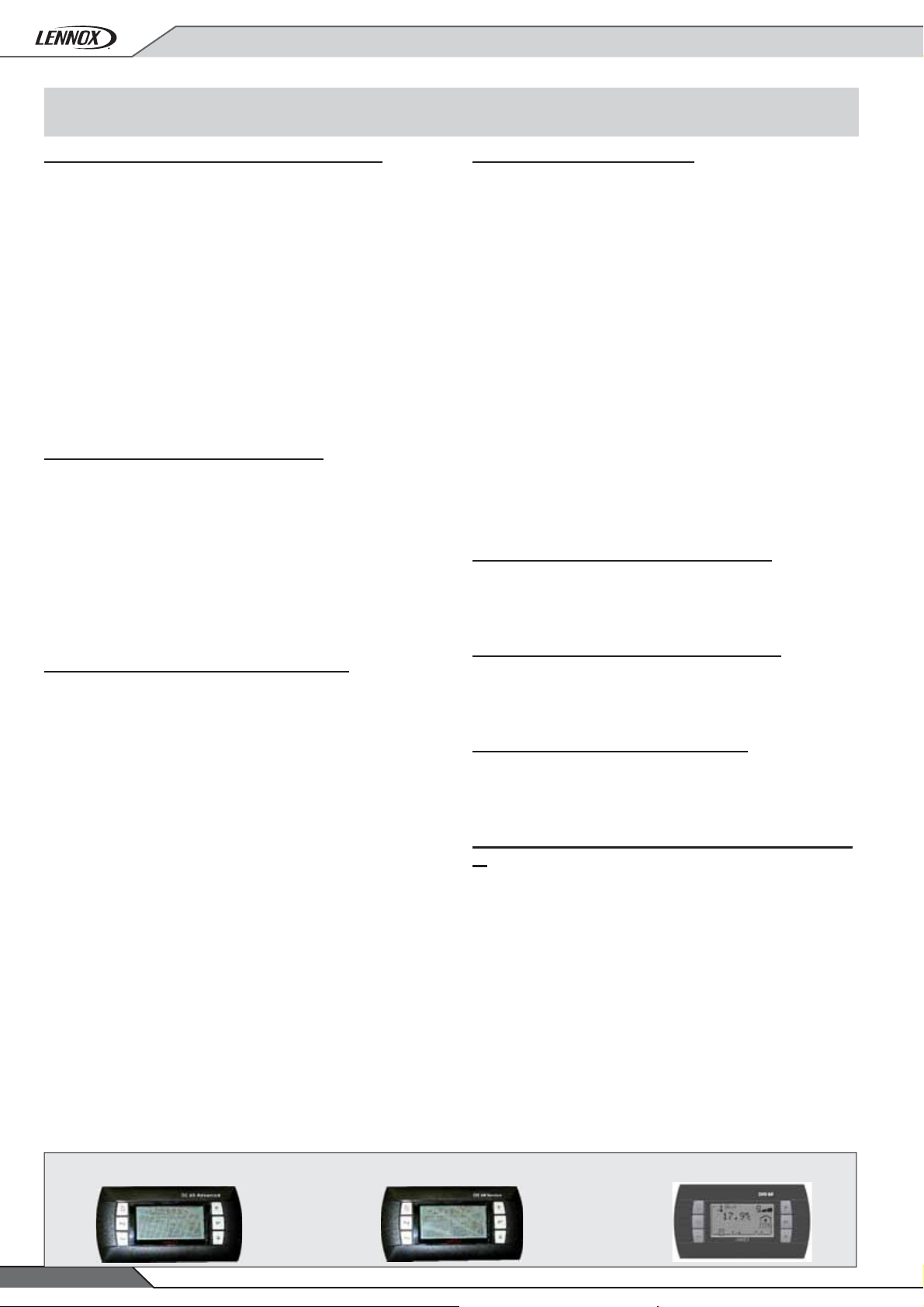
DC60 remote comfort display (supplied loose)
This is a remote controller for non-technical customer. It has
been designed to aesthetically fi t inside a room and be very easy
to use. It can be installed at maximum 50 meters from the unit.
There are two levels : In the fi rst level, ambient temperature is
provided and the setpoint temperature or offset to this setpoint
temperature can be adjusted (according to settings and rights
offered by the technician). The unit can be turned On and Off in
this level. The full level additionally provides information such
as outdoor temperature, supply temperature, ambient humidity
level, air quality , fresh air damper opening percentage, time zone
and working mode of the given time zone. DC60 Comfort display
shows faults number when the unit is in the failure mode. Customer
can reset fault thanks to a combination of keys. Time and day
of the unit can be seen and modifi ed easily through the DC60.
DS60 Service display (supplied loose)
This plug and play service display and controller allows
maintenance staff to set up, read and modify all unit parameters
(unit settings, operating time and number of compressor starts,
low and high pressure reading, airfl ow rate of supply fan, and
read the history of last 32 faults...).
This controller has been designed to be very user-friendly , with 6
different keys and a graphic display . It includes scrolling menus
and full text (no codes) explanation. It is available in English or
other languages.
BE60 Extension control board
This board has been developed for any customer who wants to
take over the control of the unit using digital or analogue input
signal. With this dry contact board option the customer can set:
• 4 digital inputs (On/Off, clear faults, various component
unloading, heating priority modifi cations, thermostat orders....)
• 4 digital Outputs (alarms reporting, components status,
scheduling time zone and operating mode status, cooling,
heating, defrost and auxiliary heating status...)
• Up to 4 analogue inputs (external temperature humidity
probes, fresh air input signal, force fan speed and temperature setpoint offset).
• 1 analogue output (Humidifi er)
Note that CLIMA TIC controller always stays in charge of all safety
algorithms, defrost operation and free cooling. This option is
required to control the unit with a “universal thermostat”.
The BE60 expansion board is an additional board fi xed on DIN rail.
This board is supplied as standard on AIRCOOLAIR condensing
unit.
Modbus communication interface RS485
Communication card using ModBus protocol with RS485.
Communication interface with a building management system.
DM60 Multi-units display (supplied loose)
The DM60 remote display can manage up to 8 units on a single
Bus. On a multiunit site it makes the installation less expensive
because, not only because of DM60 price, but because only one
bus-wire has to be connected down to the DM60. In addition to
the functions offered by the DC60 display, the DM60 display
provides the percentage of power factor for compressors and
auxiliary heater. Moreover DM60 display allows to set time zones
and to modify working modes for the given time zone. These
information are available for each of the units connected to the
Bus. It can be installed up to 1000 meters from the unit.
BACnet® communication interface RS485
Communication card using Bacnet® protocol with RS485.
Communication interface with a building management system.
LonWorks® communication interface
Communication card using LonTalk® protocol.Communication
interface with a building management system.
Modbus or BACnet® communication interface TCP/
IP
Communication card using Bacnet ® or Modbus with TCP/IP.
Communication interface with building management system.
REMOTE COMFORT DISPLAY
DC60 :
• 10 •
DS60 :
SERVICE DISPLAY
DM60 :
MULTI-UNIT DISPLAY
Application Guide • AIRCOOLAIR-AGU-1603-E
Page 13

OPTIONS
Legend :
STD = As standard
NSR = Non standard request
N/A = Non available
Cooling only Heat pump Cooling only Heat pump
Split unit Condensing unit
INDOOR SECTION : CIC AND CIH
Economizer
Exhaust module
X X N/A N/A
X X N/A N/A
Return module Size 55 - 140
Fresh air over - Return bottom Size 20 - 45
Fresh air left - Exhaust right Size 55 - 140
Filtration
High fi ltration level
G4 prefi ltre / F7 fi ltration
X X N/A N/A
Auxiliary heating
Models
N/A N/A
N/A N/A
N/A N/A
Electrical heater standard
Electrical heater medium
Electrical heater high
Electrical heater high - Modulating
Modulating hot water coil
Control
Smoke detector
Air quality sensor
Remote duct sensor
Analog dirty fi lter and fan control
Airfl ow confi guration
Vertical air supply
X X N/A N/A
X X N/A N/A
X X N/A N/A
X X N/A N/A
X X N/A N/A
X X N/A N/A
X X N/A N/A
X X N/A N/A
X X N/A N/A
X X N/A N/A
Other options
M1 insulation indoor unit
Application Guide • AIRCOOLAIR-AGU-1603-E
X X N/A N/A
• 11 •
Page 14
OPTIONS
Legend :
STD = As standard
NSR = Non standard request
N/A = Non available
OUTDOOR SECTION : ASC AND ASH
Refrigeration option
Winter cooling operation down to 0°C outdoor
temperature
Winter cooling operation down to -15°C outdoor
temperature
Service valves
Refrigerant precharged
Long distance refrigerant connection up to 65 m
Electrical and safety
Main disconnect switch
Compressor electrical protection
Models
Split unit Condensing unit
Cooling only Heat pump Cooling only Heat pump
X STD X STD
X NSR X N/A
XXXX
XXXX
X X N/A N/A
XXXX
XXXX
Condenser coil guards
Control & Communication
Advanced control pack (enthalpy and humidity
control)
Modbus communication interface RS485
Lonworks® communication interface
Bacnet® communication interface RS485
Modbus or bacnet® communication interface TCP/
IP
DC60 remote comfort display (supplied loose)
DS60 service display (supplied loose)
DM60 service display (supplied loose)
BE60 expansion control board
Other options
XXXX
X X N/A N/A
XXXX
XXXX
XXXX
XXXX
XXXX
XXXX
XXXX
X X STD STD
High static pressure up to 250 Pa Size 100 - 140 Size 100 - 230
Low noise version
Outdoor coil anticorrosion protection
Outdoor & indoor coil anticorrosion protection
Rubber anti-vibration mounts (supplied loose)
Pallet packaging
• 12 •
XXXX
XXXX
X X N/A N/A
XXXX
XXXX
Application Guide • AIRCOOLAIR-AGU-1603-E
Page 15

GENERAL DATA
LARGE DUCTED SPLIT
Cooling mode - ASC + CIC - ASH + CIH
Gross cooling capacity
Net cooling capacity
Absorbed power
Gross EER
Net EER
(1)
(1)
(1)
(1)
(1)
Heating mode - ASH + CIH
Net heating capacity
Net COP
(1)
Net absorbed power
(1)
(1)
Electrical heater capacity
Hot water coil capacity
(2)
20S 25S 30S 35S 40S
19,9 24,2 27,9 36,5 41,9
kW
19,5 23,5 27,0 35,5 40,5
6,72 8,45 9,82 12,4 14,7
3,13 3,12 3,11 3,19 3,15
2,90 2,78 2,75 2,86 2,75
kW
19,5 25 28,5 36 40
3 3 2,95 3,03 3
6,5 8,33 9,66 11,9 13,3
(3)
S
(3)
M
kW
(3)
H
10 10 10 15 15
15 15 15 20 20
20 20 20 27 27
31 38 40 56 61
Refrigerant circuit
Number of compressors/Number of circuits
Refrigerant charge per circuit (approximate)
Air treatment ventilation
Minimum airfl ow
Maximum airfl ow
Maximum available static pressure
Condensing unit ventilation
Nominal airfl ow
Acoustic data
Outdoor blower outlet sound power
Standard unit (Lw)
Outdoor blower outlet sound power
Low noise unit (Lw)
(1)
(1)
Indoor blower outlet sound power level (Lw)
kg
3
m
Pa
3
m
dB(A)
1/1 1/1 1/1 1/1 1/1
4,9 5,9 6,33 8,84 10,83
3150 4250 4650 6200 6950
/h
4100 5500 6000 8050 9050
685 672 650 729 833
/h
6800 9750 11500 11300 11000
72 76 76 77 78
70 71 70 71 72
75 82 82 82 85
(1) EUROVENT conditions data
Cooling :
Outdoor temperature = 35°C DB
Entering coil temperature 27°C DB / 19°C WB
Heating :
Outdoor temperature = 7°C DB / 6°C WB
Indoor temperature = 20°C DB
Application Guide • AIRCOOLAIR-AGU-1603-E
(2) Air inlet temperature = 20°C
Water temperature = 90-70°C
(3) S = Standard heat
M = Medium heat
H = High heat
• 13 •
Page 16

GENERAL DATA
LARGE DUCTED SPLIT
Cooling mode - ASC + CIC - ASH + CIH
Gross cooling capacity
Net cooling capacity
Absorbed power
Gross EER
Net EER
(1)
(1)
(1)
(1)
(1)
Heating mode - ASH + CIH
Net heating capacity
Net COP
(1)
Net absorbed power
(1)
(1)
Electrical heater capacity
Hot water coil capacity
(1)
45D 55D 70D 85D 100D 120D 140D
48,7 57,3 72,4 86,0 103,9 116,2 140,6
kW
46,5 55,5 69,5 82,0 100,0 111,0 135,0
17 19,8 24,8 29,8 35,7 38,9 48,2
3,28 3,17 3,3 3,33 3,26 3,44 3,3
2,73 2,8 2,8 2,75 2,8 2,85 2,80
kW
49,5 56,5 72,5 80 108 118 137
2,9 3 3 3 3,13 3,05 2,82
17,1 18,8 24,2 26,7 34,5 38,7 48,6
(3)
S
(3)
M
(3)
H
15 20 20 20 27 27 27
kW
20 27 27 27 40 40 40
27 40 40 40 50 50 50
66 91 105 113 171 183 192
Refrigerant circuit
Number of compressors/Number of circuits
Refrigerant charge per circuit (approximate)
Air treatment ventilation
Minimum airfl ow
Maximum airfl ow
Maximum available static pressure
Condensing unit ventilation
Nominal airfl ow
Acoustic data
Outdoor blower outlet sound power
Standard unit (Lw)
Outdoor blower outlet sound power
Low noise unit (Lw)
(1)
(1)
Indoor blower outlet sound power level (Lw)
2/2 2/2 2/2 2/2 3/2 3/2 3/2
kg
6,94 +
6,94
6,42 +
6,42
8,74+
8,74
10,9 +
10,9
13,98 +
11,6
17,32 +
7950 9950 12450 14000 17350 19300 21000
m3/h
9750 12850 15090 16725 22450 24950 24750
Pa
812 747 711 680 812 784 828
m3/h
2 x
9750
2 x
11500
2 x
11300
2 x
11000
22700 +
18100
+18100
79 79 80 81 82 83 87
dB(A)
74 73 74 75 76 76 81
86 80 85 87 85 87 89
11,16
22700
17,23 +
17,1
2 x
22700
(1) EUROVENT conditions data
Cooling :
Outdoor temperature = 35°C DB
Entering coil temperature 27°C DB / 19°C WB
Heating :
Outdoor temperature = 7°C DB / 6°C WB
Indoor temperature = 20°C DB
• 14 •
(2) Air inlet temperature = 20°C
Water temperature = 90-70°C
(3) S = Standard heat
M = Medium heat
H = High heat
Application Guide • AIRCOOLAIR-AGU-1603-E
Page 17
GENERAL DATA
CONDENSING UNIT
020S 025S 030S 035S 040S 045D 055D
Cooling mode - ASC
Cooling capacity
(1)
EER
(1)
kW
19,7 24,7 28,4 36,1 42 49,4 56,7
3,06 3,05 2,95 3,03 2,98 3,05 2,94
Heating mode - ASH
Heating capacity
(2)
COP
(2)
kW
19,8 25,0 28,6 36,0 40,2 50,1 57,1
3,20 3,21 3,12 3,24 2,98 3,21 3,1
Refrigerant circuit
Number of compressors/Number of circuits
Capacity steps
1/1 1/1 1/1 1/1 1/1 2/2 2/2
1111122
Electrical data
Voltage 400V/3 Ph/50Hz
Maximum absorbed power
kW
8,55 10,8 12,5 16,4 17,7 21,6 25
Acoustic data
Sound power level
(3)
dB(A)
76 78 81 80 81 81 84
CONDENSING UNIT
070D 085D 100D 120D 140D 200D 230D
Cooling mode - ASC
Cooling capacity
(1)
EER
(1)
kW
72,1 83,9 104 115 141 197 228
3,04 2,96 3,03 3,1 3,05 3,11 3,06
Heating mode - ASH
Heating capacity
(2)
COP
(2)
kW
71,9 80,3 105 114 137 191 218
3,24 3,1 3,24 3,2 3,13 3,19 3,06
Refrigerant circuit
Number of compressors/Number of circuits
Capacity steps
2/2 2/2 3/2 3/2 3/2 4/2 4/2
2222222
Electrical data
Voltage 400V/3 Ph/50Hz
Maximum absorbed power kW
32,8 35,5 45,6 48,7 59,9 83,0 96,2
Acoustic data
Sound power level
(3)
dB(A)
83 84 87 87 90 89 82
(1) Evaporating temperature = 7°C / Ambient temperature = 35°C
(2) Condensing temperature = 50°C / Ambient temperature = 7°C DB/6°C WB
(3) EUROVENT conditions data
Application Guide • AIRCOOLAIR-AGU-1603-E
• 15 •
Page 18

VENTILATION DATA
TREATMENT VENTILATION DATA
LARGE DUCTED SPLIT
ASP
Airfl ow
(m3/h)
3150
3425
3700
4100
ASP
Airfl ow
CIC/CIH 020S
(m3/h)
3150
3425
3700
4100
ASP
Airfl ow
(m3/h)
4250
4625
5000
5500
100 Pa 150 Pa 200 Pa 250 Pa
K PI RPM K PI RPM K PI RPM K PI RPM
STD 1x0,55 682 STD 1x0,55 788 HP1 1x1,1 890 HP1 1x1,1 980
STD 1x0,55 699 STD 1x0,55 800 HP1 1x1,1 896 HP1 1x1,1 984
STD 1x0,55 717 STD 1x0,55 813 HP1 1x1,1 909 HP1 1x1,1 991
STD 1x0,55 735 HP1 1x1,1 921 HP1 1x1,1 1003
No kit
300 Pa 350 Pa 400 Pa 550 Pa
K PI RPM K PI RPM K PI RPM K PI RPM
HP1 1x1,1 1060 HP2 1x1,1 1133 HP3 1x1,5 1204 HP3 1x1,5 1275
HP1 1x1,1 1068 HP2 1x1,1 1135 HP3 1x1,5 1214 HP3 1x1,5 1281
HP1 1x1,1 1074 HP2 1x1,1 1138 HP3 1x1,5 1220 HP3 1x1,5 1289
HP1 1x1,1 1083 HP2 1x1,1 1141 HP3 1x1,5 1233 HP3 1x1,5 1293
100 Pa 150 Pa 200 Pa 250 Pa 300 Pa
K PI RPM K PI RPM K PI RPM K PI RPM K PI RPM
STD 1x1,1 753 STD 1x1,1 840 HP1 1x1,5 915 HP1 1x1,5 1009 HP1 1x1,5 1085
STD 1x1,1 770 HP1 1x1,5 860 HP1 1x1,5 942 HP1 1x1,5 1021 HP1 1x1,5 1098
STD 1x1,1 806 HP1 1x1,5 883 HP1 1x1,5 956 HP1 1x1,5 1035 HP2 1x1,5 1091
STD 1x1,1 840 HP1 1x1,5 903 HP1 1x1,5 988 HP1 1x1,5 1059 HP2 1x1,5 1098
ASP
Airfl ow
CIC/CIH 025S
(m3/h)
4250
4625
5000
5500
ASP
Airfl ow
(m3/h)
4650
5050
5450
6000
ASP
Airfl ow
CIC/CIH 030S
(m3/h)
4650
5050
5450
6000
350 Pa 400 Pa 450 Pa 500 Pa 550 Pa
K PI RPM K PI RPM K PI RPM K PI RPM K PI RPM
HP2 1x1,5 1160 HP2 1x1,5 1233 HP2 1x1,5 1279 HP3 1x2,2 1358 HP3 1x2,2 1420
HP2 1x1,5 1169 HP2 1x1,5 1238 HP2 1x1,5 1281 HP3 1x2,2 1364 HP3 1x2,2 1426
HP2 1x1,5 1176 HP2 1x1,5 1246 HP3 1x2,2 1310 HP3 1x2,2 1371 HP3 1x2,2 1431
HP3 1x2,2 1195 HP3 1x2,2 1258 HP3 1x2,2 1321 HP3 1x2,2 1380 HP3 1x2,2 1441
100 Pa 150 Pa 200 Pa 250 Pa 300 Pa
K PI RPM K PI RPM K PI RPM K PI RPM K PI RPM
STD 1x1,1 797 STD 1x1,1 876 HP1 1x1,5 956 HP1 1x1,5 1038 HP2 1x2,2 1113
STD 1x1,1 822 STD 1x1,1 903 HP1 1x1,5 980 HP1 1x1,5 1051 HP2 1x2,2 1126
STD 1x1,1 856 HP1 1x1,5 932 HP1 1x1,5 1003 HP1 1x1,5 1074 HP2 1x2,2 1141
STD 1x1,1 895 HP1 1x1,5 970 HP1 1x1,5 1034 HP1 1x1,5 1098 HP2 1x2,2 1161
350 Pa 400 Pa 450 Pa 500 Pa 550 Pa
K PI RPM K PI RPM K PI RPM K PI RPM K PI RPM
HP2 1x2,2 1184 HP2 1x2,2 1251 HP2 1x2,2 1295 HP3 1x3 1380 HP3 1x3 1438
HP2 1x2,2 1197 HP2 1x2,2 1261 HP2 1x2,2 1298 HP3 1x3 1386 HP3 1x3 1445
HP2 1x2,2 1208 HP2 1x2,2 1271 HP2 1x2,2 1303 HP3 1x3 1395 HP3 1x3 1453
HP2 1x2,2 1227 HP2 1x2,2 1278 HP3 1x3 1349 HP3 1x3 1407 HP3 1x3 1465
Standard fan High pressure fan 1 (option)
STD HP1
High pressure fan 2 (option) High pressure fan 3 (option)
HP2 HP3
ASP PI (kW)
• 16 •
Available static pressure (Pa) Power input
Application Guide • AIRCOOLAIR-AGU-1603-E
Page 19

VENTILATION DATA
TREATMENT VENTILATION DATA
LARGE DUCTED SPLIT
ASP
Airfl ow
(m3/h)
6200
6650
7100
8050
ASP
Airfl ow
CIC/CIH 035S
(m3/h)
6200
6650
7100
8050
ASP
Airfl ow
(m3/h)
6950
7550
8150
9050
100 Pa 150 Pa 200 Pa 250 Pa 300 Pa
K PI RPM K PI RPM K PI RPM K PI RPM K PI RPM
STD 1x1,5 640 STD 1x1,5 720 HP1 1x2,2 788 HP1 1x2,2 849 HP1 1x2,2 912
STD 1x1,5 663 STD 1x1,5 735 HP1 1x2,2 797 HP1 1x2,2 863 HP1 1x2,2 922
STD 1x1,5 688 HP1 1x2,2 749 HP1 1x2,2 813 HP1 1x2,2 873 HP1 1x2,2 931
STD 1x1,5 735 HP1 1x2,2 788 HP1 1x2,2 848 HP1 1x2,2 903 HP2 1x3 956
350 Pa 400 Pa 450 Pa 500 Pa 550 Pa
K PI RPM K PI RPM K PI RPM K PI RPM K PI RPM
HP2 1x3 972 HP2 1x3 1028 HP2 1x3 1066 HP3 1x3 1134 HP3 1x3 1183
HP2 1x3 979 HP2 1x3 1035 HP2 1x3 1068 HP3 1x3 1139 HP3 1x3 1188
HP2 1x3 986 HP2 1x3 1044 HP2 1x3 1071 HP3 1x3 1144
HP2 1x3 1010 HP2 1x3 1052 HP3 1x3 1111 HP3 1x3 1159
No kit
100 Pa 150 Pa 200 Pa 250 Pa 300 Pa 350 Pa
K PI RPM K PI RPM K PI RPM K PI RPM K PI RPM K PI RPM
STD 1x2,2 690 STD 1x2,2 757 STD 1x2,2 821 HP1 1x2,2 882 HP2 1x3 940 HP2 1x3 997
STD 1x2,2 726 STD 1x2,2 782 HP1 1x2,2 838 HP1 1x2,2 900 HP2 1x3 956 HP2 1x3 1010
STD 1x2,2 748 STD 1x2,2 808 HP1 1x2,2 863 HP1 1x2,2 919 HP2 1x3 973 HP2 1x3 1024
STD 1x2,2 799 HP1 1x2,2 851 HP1 1x2,2 902 HP2 1x3 951 HP2 1x3 1002 HP2 1x3 1069
ASP
Airfl ow
CIC/CIH 040S
(m3/h)
6950
7550
8150
9050
ASP
Airfl ow
(m3/h)
7950
8675
9400
9750
CIC/CIH 045D
ASP
Airfl ow
(m3/h)
7950
8675
9400
9750
400 Pa 450 Pa 500 Pa 550 Pa 600 Pa
K PI RPM K PI RPM K PI RPM K PI RPM K PI RPM
HP2 1x3 1048 HP2 1x3 1103 HP3 1x4 1154 HP3 1x4 1202 HP3 1x4 1250
HP2 1x3 1053 HP3 1x4 1117 HP3 1x4 1162 HP3 1x4 1209
HP2 1x3 1059 HP3 1x4 1125 HP3 1x4 1172 HP3 1x4 1216
HP2 1x3 1069 HP3 1x4 1144 HP3 1x4 1189 HP3 1x4 1233
No kit
100 Pa 150 Pa 200 Pa 250 Pa 300 Pa
K PI RPM K PI RPM K PI RPM K PI RPM K PI RPM
STD 1x2,2 738 STD 1x2,2 800 HP1 1x3 857 HP1 1x3 912 HP1 1x3 967
STD 1x2,2 779 STD 1x2,2 833 HP1 1x3 886 HP1 1x3 938 HP1 1x3 986
STD 1x2,2 817 STD 1x2,2 867 HP1 1x3 917 HP1 1x3 966 HP1 1x3 1014
STD 1x2,2 838 HP1 1x3 884 HP1 1x3 931 HP1 1x3 979 HP1 1x3 1027
350 Pa 400 Pa 450 Pa 500 Pa 550 Pa
K PI RPM K PI RPM K PI RPM K PI RPM K PI RPM
HP1 1x3 1019 HP2 1x4 1058 HP3 1x4 1154 HP3 1x4 1168 HP3 1x4 1216
HP1 1x3 1041 HP2 1x4 1064 HP3 1x4 1136 HP3 1x4 1183 HP3 1x4 1226
HP2 1x4 1052 HP2 1x4 1073 HP3 1x4 1150 HP3 1x4 1196 HP3 1x4 1240
HP2 1x4 1056 HP3 1x4 1117 HP3 1x4 1161 HP3 1x4 1204 HP3 1x4 1250
Standard fan High pressure fan 1 (option)
STD HP1
High pressure fan 2 (option) High pressure fan 3 (option)
HP2 HP3
ASP PI (kW)
Application Guide • AIRCOOLAIR-AGU-1603-E
Available static pressure (Pa) Power input
• 17 •
Page 20

VENTILATION DATA
TREATMENT VENTILATION DATA
LARGE DUCTED SPLIT
Airfl ow
(m3/h)
9950
10825
11700
12850
Airfl ow
(m3/h)
9950
10825
11700
12850
Airfl ow
(m3/h)
12450
13550
14650
15090
ASP
100 Pa 150 Pa 200 Pa 250 Pa 300 Pa 350 Pa
K PI RPM K PI RPM K PI RPM K PI RPM K PI RPM K PI RPM
STD 1x2,2 666 STD 1x2,2 748 STD 1x2,2 828 HP1 1x3 903 HP1 1x3 967 HP1 1x3 1033
STD 1x2,2 688 STD 1x2,2 770 HP1 1x3 842 HP1 1x3 913 HP1 1x3 986 HP1 1x3 1041
STD 1x2,2 704 STD 1x2,2 786 HP1 1x3 859 HP1 1x3 931 HP1 1x3 992 HP2 1x4 1010
STD 1x2,2 741 HP1 1x3 820 HP1 1x3 881 HP1 1x3 946 HP2 1x4 971 HP2 1x4 1027
ASP
400 Pa 450 Pa 500 Pa 550 Pa 600 Pa 650 Pa
K PI RPM K PI RPM K PI RPM K PI RPM K PI RPM K PI RPM
HP2 1x4 1047 HP2 1x4 1103 HP2 1x4 1138 HP3 1x5,5 1207 HP3 1x5,5 1256 HP3 1x5,5 1303
HP2 1x4 1057 HP2 1x4 0110 HP2 1x4 1140 HP3 1x5,5 1214 HP3 1x5,5 1262 HP3 1x5,5 1309
HP2 1x4 1065 HP2 1x4 1115 HP2 1x4 1172 HP3 1x5,5 1220 HP3 1x5,5 1268
HP2 1x4 1078 HP3 1x5,5 1132 HP3 1x5,5 1182 HP3 1x5,5 1232
ASP
100 Pa 150 Pa 200 Pa 250 Pa 300 Pa 350 Pa
No kit
K PI RPM K PI RPM K PI RPM K PI RPM K PI RPM K PI RPM
STD 1x3 738 STD 1x3 819 STD 1x3 888 HP1 1x4 959 HP1 1x4 1014 HP2 1x5,5 1033
STD 1x3 776 STD 1x3 845 HP1 1x4 909 HP1 1x4 972 HP1 1x4 1033 HP2 1x5,5 1047
STD 1x3 807 HP1 1x4 871 HP1 1x4 931 HP1 1x4 993 HP2 1x5,5 1016 HP2 1x5,5 1069
STD 1x3 819 HP1 1x4 882 HP1 1x4 943 HP1 1x4 1002 HP2 1x5,5 1027 HP2 1x5,5 1078
No kit
ASP
Airfl ow
(m3/h)
12450
13550
14650
15090
ASP
Airfl ow
(m3/h)
14000
15125
16250
16725
ASP
Airfl ow
CIC/CIH 085D CIC/CIH 055DCIC/CIH 070D
(m3/h)
14000
15125
16250
16725
400 Pa 450 Pa 500 Pa 550 Pa 600 Pa 650 Pa
K PI RPM K PI RPM K PI RPM K PI RPM K PI RPM K PI RPM
HP2 1x5,5 1087 HP2 1x5,5 1125 HP3 1x7,5 1189 HP3 1x7,5 1237 HP3 1x7,5 1275 HP3 1x7,5 1329
HP2 1x5,5 1101 HP2 1x5,5 1130 HP3 1x7,5 1197 HP3 1x7,5 1245 HP3 1x7,5 1292 HP3 1x7,5 1339
HP2 1x5,5 1113 HP2 1x5,5 1137 HP3 1x7,5 1212 HP3 1x7,5 1258 HP3 1x7,5 1303
HP2 1x5,5 1117 HP2 1x5,5 1140 HP3 1x7,5 1218 HP3 1x7,5 1264 HP3 1x7,5 1307
No kit
100 Pa 150 Pa 200 Pa 250 Pa 300 Pa 350 Pa
K PI RPM K PI RPM K PI RPM K PI RPM K PI RPM K PI RPM
STD 1x4 805 STD 1x4 872 STD 1x4 937 HP1 1x5,5 995 HP2 1x7,5 1016 HP2 1x7,5 1070
STD 1x4 838 STD 1x4 898 HP1 1x5,5 959 HP1 1x5,5 1014 HP2 1x7,5 1040 HP2 1x7,5 1088
STD 1x4 863 STD 1x4 925 HP1 1x5,5 986 HP1 1x5,5 1041 HP2 1x7,5 1064 HP2 1x7,5 0110
STD 1x4 882 STD 1x4 937 HP1 1x5,5 994 HP2 1x7,5 1029 HP2 1x7,5 1073 HP2 1x7,5 1114
400 Pa 450 Pa 500 Pa 550 Pa 600 Pa
K PI RPM K PI RPM K PI RPM K PI RPM K PI RPM
HP2 1x7,5 1114 HP2 1x7,5 1172 HP3 1x7,5 1214 HP3 1x7,5 1262 HP3 1x7,5 1303
HP2 1x7,5 1122 HP3 1x7,5 1184 HP3 1x7,5 1232 HP3 1x7,5 1275 HP3 1x7,5 1310
HP2 1x7,5 1130 HP3 1x7,5 1201 HP3 1x7,5 1245 HP3 1x7,5 1289 HP3 1x7,5 1331
HP2 1x7,5 1134 HP3 1x7,5 1209 HP3 1x7,5 1253 HP3 1x7,5 1295 HP3 1x7,5 1339
Standard fan High pressure fan 1 (option)
STD HP1
High pressure fan 2 (option) High pressure fan 3 (option)
HP2 HP3
ASP PI (kW)
• 18 •
Available static pressure (Pa) Power input
Application Guide • AIRCOOLAIR-AGU-1603-E
Page 21

VENTILATION DATA
TREATMENT VENTILATION DATA
LARGE DUCTED SPLIT
ASP
Airfl ow
(m3/h)
17350
18875
20400
22450
ASP
Airfl ow
CIC/CIH 100D
(m3/h)
17350
18875
20400
22450
ASP
Airfl ow
(m3/h)
21000
22250
23500
24750
100 Pa 150 Pa 200 Pa 250 Pa 300 Pa 350 Pa
K PI RPM K PI RPM K PI RPM K PI RPM K PI RPM K PI RPM
STD 1x4 591 STD 1x4 650 STD 1x4 710 HP1 1x5,5 763 HP1 1x5,5 815 HP2 2x4 825
STD 1x4 611 STD 1x4 670 STD 1x4 730 HP1 1x5,5 777 HP1 1x5,5 827 HP2 2x4 834
STD 1x4 637 STD 1x4 690 HP1 1x5,5 744 HP1 1x5,5 792 HP2 2x4 802 HP2 2x4 846
STD 1x4 670 HP1 1x5,5 721 HP1 1x5,5 770 HP2 2x4 788 HP2 2x4 822 HP2 2x4 863
400 Pa 450 Pa 500 Pa 550 Pa 600 Pa
K PI RPM K PI RPM K PI RPM K PI RPM K PI RPM
HP2 2x4 870 HP2 2x4 903 HP3 2x4 959 HP3 2x4 997 HP3 2x4 1036
HP2 2x4 879 HP2 2x4 906 HP3 2x4 964 HP3 2x4 1003 HP3 2x4 1041
HP2 2x4 888 HP2 2x4 910 HP3 2x4 971 HP3 2x4 1009
HP2 2x4 896 HP3 2x4 945 HP3 2x4 986
No kit
No kit
100 Pa 150 Pa 200 Pa 250 Pa 300 Pa
K PI RPM K PI RPM K PI RPM K PI RPM K PI RPM
STD 1x5,5 630 STD 1x5.5 690 STD 1x5.5 743 HP1 1x7.5 792 HP2 2x4 802
STD 1x5,5 658 STD 1x5.5 710 HP1 1x7.5 763 HP1 1x7.5 810 HP2 2x4 818
STD 1x5,5 690 STD 1x5.5 736 HP1 1x7.5 784 HP1 1x7.5 829 HP2 2x4 838
STD 1x5,5 722 HP1 1x7.5 770 HP1 1x7.5 815 HP2 2x4 817 HP2 2x4 858
ASP
Airfl ow
CIC/CIH 120DCIC/CIH 140D
(m3/h)
21000
22250
23500
24750
ASP
Airfl ow
(m3/h)
21000
22250
23500
24750
ASP
Airfl ow
(m3/h)
21000
22250
23500
24750
350 Pa 400 Pa 450 Pa 500 Pa 550 Pa
K PI RPM K PI RPM K PI RPM K PI RPM K PI RPM
HP2 2x4 848 HP2 2x4 888 HP2 1x4 937 HP3 2x5,5 974 HP3 2x5,5 1014
HP2 2x4 863 HP2 2x4 899 HP3 2x5.5 945 HP3 2x5,5 986 HP3 2x5,5 1022
HP2 2x4 876 HP2 2x4 902 HP3 2x5.5 959 HP3 2x5,5 994 HP3 2x5,5 1031
HP2 2x4 892 HP2 2x4 910 HP3 2x5,5 974 HP3 1x5,5 1010
No kit
100 Pa 150 Pa 200 Pa 250 Pa 300 Pa 350 Pa
K PI RPM K PI RPM K PI RPM K PI RPM K PI RPM K PI RPM
STD 1x5,5 611 STD 1x5,5 665 STD 1x5,5 718 HP1 1x7.5 770 HP1 1x7.5 815 HP2 2x4 823
STD 1x5,5 630 STD 1x5,5 681 STD 1x5,5 730 HP1 1x7.5 780 HP1 1x7.5 827 HP2 2x4 832
STD 1x5,5 650 STD 1x5,5 697 STD 1x5,5 750 HP1 1x7.5 792 HP1 1x7.5 837 HP2 2x4 841
STD 1x5,5 665 STD 1x5,5 710 HP1 1x7.5 761 HP1 1x7.5 806 HP2 2x4 813 HP2 2x4 851
400 Pa 450 Pa 500 Pa 550 Pa 600 Pa
K PI RPM K PI RPM K PI RPM K PI RPM K PI RPM
HP2 2x4 867 HP2 2x4 900 HP3 2x5,5 949 HP3 2x5,5 986 HP3 2x5,5 1026
HP2 2x4 875 HP2 2x4 903 HP3 2x5,5 954 HP3 2x5,5 993 HP3 2x5,5 1030
HP2 2x4 882 HP2 2x4 906 HP3 2x5,5 959 HP3 2x5,5 999 HP3 2x5,5 1035
HP2 2x4 890 HP2 2x4 910 HP3 2x5,5 968 HP3 2x5,5 1004 HP3 2x5,5 1041
Standard fan High pressure fan 1 (option)
STD HP1
High pressure fan 2 (option) High pressure fan 3 (option)
HP2 HP3
ASP PI (kW)
Application Guide • AIRCOOLAIR-AGU-1603-E
Available static pressure (Pa) Power input
• 19 •
Page 22

VENTILATION DATA
RETURN VENTILATION DATA
055D
Closed pulley
1 turn
2 turns
3 turns
4 turns
Pulley position
085D
Closed pulley
1 turn
2 turns
3 turns
4 turns
Pulley position
Airfl ow
(
rpm) ↓
755
715
675
635
595
Airfl ow
rpm) ↓
(
755
715
675
635
595
3
Airfl ow (m
/h)
9950 10825 11700 12850
ASP PI ASP PI ASP PI ASP PI
255 2,37 257 2,56 260 2,77 260 3,05
230 2,11 232 2,30 234 2,48 233 2,75
207 1,88 208 2,05 210 2,23 207 2,48
184 1,67 184 1,82 184 1,99 180 2,22
162 1,47 162 1,61 160 1,77 155 1,98
3
Airfl ow (m
/h)
14000 15125 16250 16725
ASP PI ASP PI ASP PI ASP PI
260 3,44 255 3,77 250 4,13
230 3,12 225 3,43 215 3,75 212 3,90
202 2,82 195 3,11 183 3,41 178 3,55
173 2,53 165 2,80 153 3,09 145 3,22
145 2,27 135 2,52 120 2,79 115 2,91
••
070D
Closed pulley
1 turn
2 turns
3 turns
4 turns
Pulley position
100D
Closed pulley
1 turn
2 turns
3 turns
4 turns
Pulley position
Airfl ow
(
rpm) ↓
755
715
675
635
595
Airfl ow
rpm) ↓
(
672
636
601
565
529
3
Airfl ow (m
/h)
12450 13550 14650 15090
ASP PI ASP PI ASP PI ASP PI
260 2,93 260 3,22 258 3,52 255 3,65
235 2,64 233 2,91 228 3,20 225 3,32
208 2,37 205 2,62 198 2,90 195 3,00
182 2,12 176 2,36 168 2,61 165 2,72
157 1,89 150 2,11 140 2,35 135 2,44
Airfl ow (m
3
/h)
17350 18875 20400 22450
ASP PI ASP PI ASP PI ASP PI
293 3,81 293 4,25 291 4,60
263 3,46 261 2,88 258 4,22 251 4,77
234 3,15 232 3,49 227 3,86 218 4,38
205 2,83 202 3,15 196 3,48 185 3,98
178 2,52 173 2,81 166 3,13 153 3,58
••
120D
Closed pulley
1 turn
2 turns
3 turns
4 turns
Pulley position
Airfl ow
rpm) ↓
(
19300 21000 22700 24750
ASP PI ASP PI ASP PI ASP PI
381 380 380 373
766
343 340 337 330
725
305 300 297 287
684
268 263 257 245
644
232 227 220 205
603
EXHAUST VENTILATION DATA
020S - 025S - 030S
Airfl ow (m
Airfl ow m3/h
Available static pressure Pa
Airfl ow m
2000 2500 2750
160 105 75
060S-070S-055D-070D-85D
3
/h
6000 7000 8000
3
/h)
140D
Closed pulley
1 turn
2 turns
3 turns
4 turns
Pulley position
Airfl ow
rpm) ↓
(
766
725
684
644
603
21000 22700 24750
ASP PI ASP PI ASP PI
380 380 373
340 337 330
300 297 287
263 257 245
227 220 205
Airfl ow (m3/h)
035S - 040S - 042S - 045D
Airfl ow m3/h
Available static pressure Pa
3000 3500 4000
210 180 130
100D
Airfl ow m3/h
13200 14300 15400 16500
Available static pressure Pa
260 200 90
Available static pressure Pa
120D - 140D
Airfl ow m3/h
Available static pressure Pa
ASP PI (kW)
• 20 •
Available static pressure (Pa) Power input
13200 14300 15400 16500
230 200 150 50
230 200 150 50
Application Guide • AIRCOOLAIR-AGU-1603-E
Page 23

VENTILATION DATA
OPTION PRESSURE DROP TABLE
Airfl ow
Options
Economizer
Hot water coil
Airfl ow
Options
Economizer
Hot water coil
Unit size
m3/h
PaG4/F7 fi ltration
Unit size
m3/h
PaG4/F7 fi ltration
020S 025S 030S 035S
3150 3425 3700 4100 4250 4625 5000 5500 4650 5050 5450 6000 6200 6650 7100 8050
13 17 20 25 24 31 37 45 28 37 43 54 26 30 34 43
85 93 102 115 120 133 146 165 133 148 163 184 128 140 152 178
15 17 20 23 25 28 32 38 29 33 37 44 25 29 32 39
040S / 042S 045D 055D / 060S
6950 7550 8150 9050 7950 8675 9400 9750 9950 10825 11700 12850
33 38 44 52 42 48 55 58 11 13 16 19
148 164 181 208 175 197 219 230 123 136 150 169
31 35 40 47 38 44 50 54 24 27 31 36
Airfl ow
Options
Economizer
Hot water coil
Airfl ow
Options
Economizer
Hot water coil
Unit size
m3/h
PaG4/F7 fi ltration
Unit size
m3/h
PaG4/F7 fi ltration
070D / 070S 085D 100D
12450 13550 14650 15090 14000 15125 16250 16725 17350 18875 20400 22450
18 21 24 26 22 26 30 32 5 10 15 20
162 181 200 208 188 209 230 239 135 150 166 187
34 39 44 47 41 47 53 55 23 26 30 35
120D 140D
19300 21000 22700 24950 21000 22250 23500 24750
15 20 25 30 20 25 30 35
154 172 190 215 133 143 153 164
27 31 35 41 31 34 37 41
Application Guide • AIRCOOLAIR-AGU-1603-E
• 21 •
Page 24

PERFORMANCES - SPLIT UNITS
COOLING CAPACITIES
ASC/ASH + CIC/CIH 020S
Air inlet temperature at condenser (dry bulb)
20 °C 25 °C 30 °C 35°C 40 °C 45 °C
Airfl ow
3
m
/h
MinimumNominalMaximum
Indoor wet
bulb°CIndoor dry bulb
16
19
3150
22
16
19
3700
22
16
19
4100
22
GC SC AC GC SC AC GC SC AC GC SC AC GC SC AC GC SC AC
°C
21 19,6 12,1 4,4 19,1 11,9 4,7 11,6 18,4 5,1 17,7 11,2 5,6 16,9 10,9 6,3 15,9 10,4 7,2
24 19,7 14,7 4,4 19,2 14,4 4,7 14,1 18,5 5,1 17,8 13,8 5,6 17,0 13,3 6,3 16,0 12,8 7,2
27 19,7 17,3 4,4 19,2 17,0 4,7 16,7 18,6 5,1 17,9 16,3 5,6 17,0 15,8 6,3 16,1 15,2 7,2
24 21,4 11,9 4,6 20,8 11,7 4,9 11,4 20,1 5,3 19,3 11,0 5,8 18,4 10,7 6,4 17,4 10,3 7,4
27 21,5 14,5 4,6 20,9 14,2 4,9 13,9 20,2 5,3 19,4 13,6 5,8 18,5 13,2 6,4 17,5 12,7 7,4
30 21,5 17,0 4,6 20,9 16,7 4,9 16,4 20,3 5,3 19,5 16,1 5,8 18,6 15,6 6,5 17,6 15,1 7,4
27 23,3 11,7 4,7 22,7 11,4 5,0 11,1 21,9 5,4 21,1 10,8 6,0 20,1 10,5 6,6 19,1 10,1 7,6
30 23,4 14,2 4,7 22,8 13,9 5,0 13,6 22,0 5,5 21,2 13,3 6,0 20,2 12,9 6,6 19,2 12,5 7,6
33 23,5 16,6 4,7 22,8 16,4 5,1 16,1 22,1 5,5 21,3 15,8 6,0 20,3 15,4 6,7 19,3 14,9 7,6
21 20,1 12,6 4,5 19,5 12,4 4,9 12,1 18,9 5,3 18,1 11,7 5,8 17,2 11,3 6,4 16,3 10,9 7,4
24 20,2 15,5 4,5 19,6 15,3 4,9 15,0 19,0 5,3 18,2 14,6 5,8 17,4 14,1 6,4 16,4 13,5 7,4
27 20,3 18,4 4,5 19,7 18,2 4,9 17,8 19,1 5,3 18,3 17,4 5,8 17,4 16,8 6,4 16,5 15,9 7,4
24 21,9 12,4 4,7 21,3 12,1 5,0 11,8 20,6 5,4 19,8 11,5 5,9 18,8 11,2 6,6 17,8 10,7 7,6
27 22,0 15,3 4,7 21,4 15,0 5,0 14,7 20,7 5,4 19,9 14,4 5,9 19,0 13,9 6,6 17,9 13,4 7,6
30 22,1 18,2 4,7 21,5 17,9 5,0 17,6 20,8 5,4 20,0 17,2 6,0 19,0 16,7 6,6 18,0 16,1 7,6
27 23,9 12,1 4,8 23,2 11,8 5,2 11,6 22,4 5,6 21,6 11,3 6,1 20,6 10,9 6,8 19,5 10,6 7,8
30 24,0 15,0 4,8 23,3 14,7 5,2 14,4 22,6 5,6 21,7 14,1 6,1 20,7 13,7 6,8 19,6 13,3 7,8
33 24,1 17,8 4,8 23,4 17,6 5,2 17,3 22,6 5,6 21,8 16,9 6,1 20,8 16,5 6,8 19,7 16,0 7,8
21 20,5 13,0 4,5 19,9 12,8 4,8 12,5 19,2 5,2 18,4 12,1 5,7 17,5 11,7 6,4 16,5 11,3 7,3
24 20,6 16,2 4,5 20,0 15,9 4,8 15,6 19,3 5,2 18,5 15,2 5,7 17,7 14,7 6,4 16,7 14,1 7,3
27 20,7 19,3 4,5 20,1 19,0 4,8 18,7 19,4 5,2 18,7 18,2 5,7 17,8 17,7 6,4 16,8 17,0 7,3
24 22,3 12,8 4,7 21,7 12,5 5,0 12,2 20,9 5,4 20,1 11,9 5,9 19,1 11,5 6,5 18,1 11,1 7,5
27 22,4 15,9 4,7 21,8 15,7 5,0 15,3 21,1 5,4 20,2 15,0 5,9 19,3 14,5 6,6 18,2 14,0 7,5
30 22,5 19,1 4,7 21,9 18,8 5,0 18,5 21,2 5,4 20,3 18,0 5,9 19,4 17,5 6,6 18,3 16,9 7,5
27 24,3 12,4 4,8 23,6 12,2 5,2 11,9 22,8 5,6 21,9 11,6 6,1 20,9 11,3 6,8 19,8 10,9 7,7
30 24,4 15,6 4,8 23,7 15,3 5,2 15,0 22,9 5,6 22,0 14,7 6,1 21,0 14,3 6,8 19,9 13,8 7,7
33 24,5 18,7 4,8 23,8 18,5 5,2 18,1 23,0 5,6 22,1 17,8 6,1 21,1 17,3 6,8 20,0 16,8 7,7
HEATING CAPACITIES
ASH+CIH 020S
-10 °C -5 °C 0 °C 5°C 7 °C 10 °C 15 °C
Airfl ow
m3/h
MinimumNominalMaximum
Indoor fan power input (kw)
Minimum airfl ow Nominal airfl ow Maximum airfl ow
Outdoor fan power input (kw)
Nominal airfl ow
Indoor dry bulb
°C
15 12,6 3,88 14,6 4,31 16,6 4,74 18,7 5,17 19,5 5,35 20,6 5,62 22,6 6,09
18 12,6 4,21 14,6 4,65 16,5 5,09 18,5 5,54 19,3 5,73 20,5 6,01 22,4 6,52
20 12,6 4,44 14,6 4,89 16,5 5,34 18,5 5,81 19,2 6,00 20,4 6,30 22,3 6,82
3150
3700
4100
23 12,6 4,82 14,5 5,28 16,5 5,75 18,4 6,24 19,1 6,44 20,3 6,76 22,1 7,32
25 12,6 5,10 14,5 5,56 16,4 6,04 18,3 6,55 19,1 6,76 20,2 7,09 22,0 7,69
27 12,6 5,39 14,5 5,86 16,4 6,35 18,3 6,88 19,0 7,10 20,1 7,45 21,9 8,07
15 12,7 3,77 14,8 4,17 16,9 4,56 18,9 4,95 19,7 5,11 20,9 5,35 23,0 5,78
19 12,7 4,20 14,7 4,60 16,7 5,01 18,7 5,42 19,5 5,59 20,7 5,85 22,7 6,31
20 12,7 4,31 14,7 4,72 16,7 5,13 18,7 5,55 19,5 5,72 20,7 5,98 22,6 6,45
23 12,7 4,68 14,7 5,10 16,6 5,52 18,6 5,95 19,4 6,13 20,5 6,41 22,5 6,91
25 12,7 4,96 14,7 5,37 16,6 5,80 18,5 6,25 19,3 6,43 20,4 6,72 22,4 7,24
27 12,7 5,24 14,7 5,66 16,6 6,10 18,5 6,56 19,2 6,75 20,4 7,05 22,2 7,59
15 12,7 3,64 14,9 4,02 17,0 4,38 19,0 4,75 19,9 4,90 21,1 5,13 23,2 5,52
19 12,7 4,05 14,8 4,44 16,8 4,82 18,8 5,20 19,7 5,36 20,9 5,60 22,9 6,01
20 12,7 4,17 14,7 4,55 16,8 4,93 18,8 5,32 19,6 5,48 20,8 5,72 22,8 6,15
23 12,7 4,53 14,7 4,92 16,7 5,31 18,7 5,71 19,5 5,87 20,6 6,13 22,6 6,58
25 12,7 4,79 14,7 5,18 16,6 5,58 18,6 5,99 19,4 6,15 20,6 6,42 22,5 6,88
27 12,7 5,08 14,7 5,46 16,6 5,86 18,5 6,28 19,3 6,45 20,7 6,73 22,4 7,21
NH AC NH AC NH AC NH AC NH AC NH AC NH AC
0,31 0,38 0,44
0,4
Air inlet temperature at condenser (dry bulb)
GC
(kW) :
• 22 •
Gross cooling capacity Net heating capacity Sensible cooling capacity
NH
(kW) :
SC
(kW) :
Application Guide • AIRCOOLAIR-AGU-1603-E
Compressor absorbed
AC
power
(kW) :
Page 25

PERFORMANCES - SPLIT UNITS
COOLING CAPACITIES
ASC/ASH + CIC/CIH 025S
20 °C 25 °C 30 °C 35°C 40 °C 45 °C
Air inlet temperature at condenser (dry bulb)
Airfl ow
3
m
/h
MinimumNominalMaximum
Indoor wet
bulb°CIndoor dry bulb
16
19
4250
22
16
19
5000
22
16
19
5500
22
GC SC AC GC SC AC GC SC AC GC SC AC GC SC AC GC SC AC
°C
21 24,1 14,8 5,1 23,4 14,5 5,5 22,7 14,1 6,0 21,8 13,7 6,6 20,7 13,3 7,3 19,6 12,7 8,4
24 24,2 18,0 5,2 23,5 17,7 5,5 22,8 17,3 6,0 21,9 16,9 6,6 20,9 16,4 7,3 19,7 15,8 8,4
27 24,2 21,2 5,2 23,6 20,9 5,5 22,8 20,6 6,0 21,9 20,1 6,6 20,9 19,5 7,3 19,8 18,8 8,4
24 26,2 14,5 5,3 25,5 14,2 5,7 24,7 13,8 6,1 23,7 13,4 6,7 22,6 13,0 7,5 21,4 12,5 8,6
27 26,3 17,7 5,3 25,6 17,4 5,7 24,8 17,0 6,2 23,8 16,6 6,7 22,7 16,1 7,5 21,5 15,6 8,6
30 26,4 20,9 5,3 25,7 20,6 5,7 24,9 20,2 6,2 23,9 19,8 6,7 22,8 19,2 7,5 21,6 18,6 8,6
27 28,5 14,2 5,5 27,7 13,9 5,8 26,8 13,5 6,3 25,8 13,1 6,9 24,6 12,7 7,7 23,3 12,3 8,8
30 28,6 17,3 5,5 27,8 17,0 5,9 26,9 16,7 6,3 25,9 16,3 6,9 24,7 15,8 7,7 23,4 15,3 8,8
33 28,7 20,4 5,5 27,9 20,1 5,9 27,0 19,8 6,3 26,0 19,4 6,9 24,8 18,9 7,7 23,5 18,3 8,8
21 24,5 15,2 5,4 23,8 14,9 5,8 23,0 14,5 6,3 22,1 14,1 6,9 21,0 13,7 7,7 19,8 13,1 8,9
24 24,6 18,8 5,4 23,9 18,5 5,8 23,1 18,1 6,3 22,2 17,7 6,9 21,2 17,1 7,7 20,0 16,4 8,9
27 24,7 22,4 5,4 24,0 22,1 5,8 23,2 21,7 6,3 22,3 21,2 6,9 21,2 20,5 7,7 20,2 19,5 8,8
24 26,7 14,9 5,6 25,9 14,6 6,0 25,0 14,2 6,5 24,0 13,8 7,1 22,9 13,4 7,9 21,6 12,9 9,1
27 26,8 18,5 5,6 26,1 18,2 6,0 25,2 17,8 6,5 24,2 17,4 7,1 23,0 16,9 7,9 21,8 16,3 9,1
30 26,9 22,1 5,6 26,2 21,8 6,0 25,3 21,4 6,5 24,3 20,9 7,1 23,2 20,3 7,9 21,9 19,6 9,1
27 29,0 14,5 5,7 28,2 14,2 6,1 27,2 13,9 6,6 26,1 13,5 7,3 24,9 13,1 8,1 23,6 12,6 9,3
30 29,1 18,1 5,7 28,3 17,8 6,2 27,4 17,4 6,7 26,3 17,0 7,3 25,1 16,6 8,1 23,8 16,0 9,3
33 29,3 21,6 5,8 28,4 21,4 6,2 27,5 21,0 6,7 26,4 20,5 7,3 25,2 20,0 8,2 23,9 19,4 9,3
21 24,9 15,6 5,4 24,2 15,3 5,8 23,4 15,0 6,2 22,4 14,5 6,8 21,3 14,0 7,5 20,1 13,5 8,6
24 25,0 19,5 5,4 24,3 19,2 5,8 23,5 18,8 6,2 22,6 18,3 6,8 21,5 17,7 7,5 20,3 17,0 8,6
27 25,1 23,4 5,4 24,4 23,1 5,8 23,6 22,6 6,2 22,9 22,1 6,9 21,9 21,1 7,7 20,7 19,9 8,8
24 27,1 15,3 5,5 26,3 15,0 5,9 25,4 14,6 6,4 24,4 14,2 7,0 23,2 13,8 7,7 22,0 13,3 8,8
27 27,3 19,2 5,6 26,5 18,9 5,9 25,6 18,5 6,4 24,6 18,0 7,0 23,4 17,5 7,7 22,1 16,9 8,8
30 27,4 23,1 5,6 26,6 22,8 5,9 25,7 22,4 6,4 24,7 21,8 7,0 23,5 21,2 7,8 22,2 20,5 8,8
27 29,5 14,9 5,7 28,6 14,5 6,1 27,6 14,2 6,6 26,5 13,9 7,2 25,3 13,4 8,0 23,9 13,0 9,1
30 29,6 18,8 5,7 28,8 18,4 6,1 27,8 18,1 6,6 26,7 17,7 7,2 25,5 17,2 8,0 24,1 16,6 9,1
33 29,7 22,6 5,7 28,9 22,3 6,1 27,9 21,9 6,6 26,8 21,5 7,2 25,6 20,9 8,0 24,2 20,3 9,1
HEATING CAPACITIES
ASH+CIH 025S
-10 °C -5 °C 0 °C 5°C 7 °C 10 °C 15 °C
Airfl ow
m3/h
MinimumNominalMaximum
Indoor fan power input (kw)
Minimum airfl ow Nominal airfl ow Maximum airfl ow
Outdoor fan power input (kw)
Nominal airfl ow
Indoor dry bulb
°C
15 16,1 4,79 18,7 5,27 21,24 5,7 23,75 6,2 24,75 6,4 26,23 6,7 28,67 7,30
18 16,0 5,17 18,6 5,67 21,10 6,2 23,57 6,7 24,54 6,9 26,00 7,2 28,39 7,80
20 16,0 5,45 18,5 5,96 21,01 6,5 23,44 7,0 24,41 7,2 25,84 7,6 28,20 8,17
4250
5000
5500
23 15,9 5,91 18,4 6,42 20,87 6,9 23,26 7,5 24,21 7,7 25,61 8,1 27,93 8,78
25 15,9 6,24 18,4 6,77 20,79 7,3 23,14 7,9 24,08 8,1 25,46 8,5 27,75 9,23
27 15,9 6,60 18,3 7,13 20,70 7,7 23,03 8,3 23,95 8,6 25,32 8,9 27,57 9,71
15 16,5 4,76 19,1 5,20 21,75 5,6 24,32 6,1 25,34 6,2 26,86 6,5 29,36 7,00
19 16,4 5,29 19,0 5,73 21,56 6,2 24,07 6,6 25,07 6,8 26,55 7,1 28,99 7,63
20 16,4 5,43 18,9 5,87 21,52 6,3 24,01 6,8 25,00 6,9 26,47 7,3 28,89 7,81
23 16,4 5,89 18,9 6,33 21,38 6,8 23,83 7,3 24,80 7,5 26,24 7,8 28,62 8,36
25 16,3 6,22 18,8 6,66 21,29 7,1 23,71 7,6 24,67 7,8 26,09 8,2 28,43 8,77
27 16,3 6,58 18,8 7,02 21,21 7,5 23,59 8,0 24,54 8,2 25,94 8,6 28,25 9,21
15 16,5 4,61 19,2 5,02 21,86 5,4 24,48 5,8 25,52 6,0 27,06 6,2 29,60 6,69
19 16,5 5,12 19,1 5,53 21,68 5,9 24,23 6,3 25,24 6,5 26,74 6,8 29,22 7,28
20 16,4 5,26 19,1 5,67 21,63 6,1 24,17 6,5 25,17 6,7 26,67 6,9 29,13 7,44
23 16,4 5,70 18,9 6,11 21,50 6,5 23,98 7,0 24,97 7,1 26,44 7,4 28,85 7,96
25 16,4 6,03 18,9 6,43 21,41 6,8 23,87 7,3 24,84 7,5 26,29 7,8 28,67 8,33
27 16,3 6,37 18,9 6,77 21,32 7,2 23,75 7,7 24,71 7,9 26,14 8,2 28,49 8,73
NH AC NH AC NH AC NH AC NH AC NH AC NH AC
0,54 0,69 0,80
0,67
Air inlet temperature at condenser (dry bulb)
GC
Gross cooling capacity Net heating capacity Sensible cooling capacity
(kW) :
Application Guide • AIRCOOLAIR-AGU-1603-E
NH
(kW) :
SC
(kW) :
Compressor absorbed
AC
power
(kW) :
• 23 •
Page 26

PERFORMANCES - SPLIT UNITS
COOLING CAPACITIES
ASC/ASH + CIC/CIH 030S
Air inlet temperature at condenser (dry bulb)
20 °C 25 °C 30 °C 35°C 40 °C 45 °C
Airfl ow
3
m
/h
MinimumNominalMaximum
Indoor wet
bulb°CIndoor dry bulb
16
19
4650
22
16
19
5450
22
16
19
6000
22
GC SC AC GC SC AC GC SC AC GC SC AC GC SC AC GC SC AC
°C
21 27,9 17,0 5,9 27,1 16,6 6,3 26,2 16,2 6,9 25,1 15,7 7,6 23,8 15,1 8,5 22,3 14,4 9,8
24 28,0 20,6 5,9 27,2 20,3 6,3 26,3 19,8 6,9 25,1 19,2 7,6 23,8 18,6 8,5 22,4 17,8 9,9
27 28,1 24,3 5,9 27,3 23,9 6,3 26,3 23,4 6,9 25,2 22,8 7,6 23,9 22,0 8,5 22,4 21,1 9,9
24 30,4 16,7 6,0 29,5 16,3 6,5 28,5 15,9 7,1 27,3 15,4 7,8 25,9 14,8 8,7 24,3 14,2 10,1
27 30,5 20,3 6,0 29,6 19,9 6,5 28,6 19,5 7,1 27,4 18,9 7,8 26,0 18,3 8,7 24,4 17,6 10,1
30 30,6 23,9 6,0 29,7 23,5 6,5 28,7 23,0 7,1 27,5 22,5 7,8 26,1 21,8 8,7 24,5 20,9 10,1
27 33,1 16,3 6,2 32,1 15,9 6,7 31,0 15,5 7,2 29,7 15,1 8,0 28,2 14,6 8,9 26,6 14,0 10,3
30 33,2 19,8 6,2 32,2 19,5 6,7 31,1 19,0 7,3 29,8 18,6 8,0 28,3 18,0 8,9 26,7 17,3 10,3
33 33,3 23,3 6,2 32,3 23,0 6,7 31,2 22,6 7,3 29,9 22,1 8,0 28,4 21,4 9,0 26,8 20,7 10,3
21 28,5 17,5 6,2 27,7 17,1 6,6 26,6 16,7 7,2 25,5 16,2 8,0 24,1 15,6 9,0 22,6 14,9 10,4
24 28,6 21,6 6,2 27,8 21,2 6,6 26,8 20,7 7,2 25,6 20,1 8,0 24,2 19,4 9,0 22,7 18,5 10,4
27 28,7 25,6 6,2 27,8 25,2 6,6 26,8 24,7 7,2 25,7 24,0 8,0 24,3 23,2 9,0 23,0 22,1 10,2
24 31,0 17,2 6,3 30,1 16,8 6,8 29,0 16,3 7,4 27,7 15,9 8,1 26,3 15,3 9,2 24,7 14,7 10,6
27 31,1 21,2 6,3 30,2 20,8 6,8 29,1 20,4 7,4 27,9 19,8 8,2 26,4 19,2 9,2 24,8 18,4 10,6
30 31,2 25,2 6,3 30,3 24,9 6,8 29,2 24,4 7,4 27,9 23,8 8,2 26,5 23,0 9,2 24,9 22,1 10,6
27 33,7 16,7 6,5 32,7 16,3 7,0 31,5 15,9 7,6 30,2 15,5 8,3 28,7 15,0 9,4 27,0 14,4 10,8
30 33,8 20,7 6,5 32,8 20,4 7,0 31,7 19,9 7,6 30,3 19,4 8,4 28,8 18,8 9,4 27,1 18,2 10,8
33 33,9 24,7 6,5 32,9 24,4 7,0 31,8 23,9 7,6 30,4 23,4 8,4 28,9 22,7 9,4 27,2 21,9 10,9
21 29,0 18,0 6,1 28,1 17,6 6,6 27,1 17,2 7,1 25,9 16,7 7,8 24,5 16,0 8,7 23,0 15,3 10,0
24 29,1 22,4 6,1 28,3 22,0 6,6 27,2 21,5 7,1 26,0 20,9 7,8 24,6 20,1 8,7 23,1 19,2 10,0
27 29,2 26,8 6,1 28,3 26,4 6,6 27,3 25,8 7,1 26,1 25,1 7,8 25,0 24,0 8,9 23,6 22,6 10,1
24 31,6 17,6 6,3 30,6 17,2 6,7 29,5 16,8 7,3 28,2 16,3 8,0 26,7 15,8 8,9 25,1 15,1 10,3
27 31,7 22,0 6,3 30,7 21,6 6,7 29,6 21,1 7,3 28,3 20,6 8,0 26,9 19,9 8,9 25,2 19,1 10,3
30 31,8 26,4 6,3 30,8 26,0 6,7 29,7 25,5 7,3 28,4 24,8 8,0 27,0 24,0 9,0 25,3 23,1 10,3
27 34,3 17,1 6,4 33,3 16,8 6,9 32,1 16,4 7,5 30,7 15,9 8,2 29,1 15,4 9,2 27,4 14,8 10,5
30 34,4 21,5 6,5 33,4 21,1 6,9 32,2 20,7 7,5 30,8 20,2 8,2 29,3 19,6 9,2 27,6 18,9 10,5
33 34,5 25,9 6,5 33,5 25,5 6,9 32,3 25,0 7,5 31,0 24,5 8,2 29,4 23,8 9,2 27,7 22,9 10,5
HEATING CAPACITIES
ASH+CIH 030S
-10 °C -5 °C 0 °C 5°C 7 °C 10 °C 15 °C
Airfl ow
m3/h
MinimumNominalMaximum
Indoor fan power input (kw)
Minimum airfl ow Nominal airfl ow Maximum airfl ow
Outdoor fan power input (kw)
Nominal airfl ow
Indoor dry bulb
°C
15 18,4 5,37 21,4 5,96 24,3 6,54 27,1 7,11 28,3 7,34 29,9 7,69 32,7 8,30
18 18,4 5,83 21,3 6,43 24,1 7,03 26,9 7,62 28,0 7,86 29,6 8,23 32,3 8,88
20 18,4 6,16 21,3 6,77 24,0 7,38 26,8 7,99 27,9 8,24 29,4 8,62 32,1 9,30
4650
5450
6000
23 18,4 6,69 21,2 7,32 23,9 7,94 26,6 8,58 27,7 8,85 29,2 9,26 31,8 9,98
25 18,5 7,08 21,2 7,71 23,9 8,35 26,5 9,01 27,5 9,29 29,1 9,72 31,6 10,48
27 18,5 7,48 21,2 8,12 23,8 8,78 26,4 9,47 27,4 9,75 28,9 10,20 31,4 11,01
15 18,8 5,33 21,8 5,88 24,8 6,41 27,7 6,93 28,9 7,14 30,6 7,46 33,5 8,00
19 18,8 5,96 21,7 6,51 24,6 7,05 27,5 7,60 28,6 7,82 30,2 8,16 33,0 8,74
20 18,8 6,13 21,7 6,68 24,6 7,23 27,4 7,78 28,5 8,00 30,1 8,34 32,9 8,94
23 18,8 6,67 21,6 7,22 24,4 7,78 27,2 8,35 28,3 8,58 29,9 8,94 32,5 9,58
25 18,8 7,05 21,6 7,61 24,4 8,18 27,1 8,76 28,1 9,00 29,7 9,38 32,3 10,04
27 18,8 7,46 21,6 8,02 24,3 8,59 26,9 9,19 28,0 9,44 29,6 9,83 32,1 10,53
15 18,9 5,12 21,9 5,65 24,9 6,15 27,9 6,64 29,1 6,83 30,9 7,13 33,8 7,64
19 18,8 5,73 21,8 6,26 24,7 6,76 27,6 7,27 28,8 7,48 30,5 7,79 33,3 8,33
20 18,8 5,90 21,8 6,42 24,7 6,93 27,6 7,44 28,7 7,65 30,4 7,97 33,2 8,52
23 18,8 6,42 21,7 6,94 24,6 7,45 27,4 7,98 28,5 8,19 30,1 8,53 32,8 9,11
25 18,8 6,79 21,7 7,31 24,5 7,83 27,2 8,36 28,3 8,59 29,9 8,93 32,6 9,53
27 18,8 7,18 21,6 7,70 24,4 8,22 27,1 8,77 28,2 9,00 29,8 9,35 32,4 9,98
NH AC NH AC NH AC NH AC NH AC NH AC NH AC
0,68 0,86 1
0,8
Air inlet temperature at condenser (dry bulb)
GC
(kW) :
• 24 •
Gross cooling capacity Net heating capacity Sensible cooling capacity
NH
(kW) :
SC
(kW) :
Application Guide • AIRCOOLAIR-AGU-1603-E
Compressor absorbed
AC
power
(kW) :
Page 27

PERFORMANCES - SPLIT UNITS
COOLING CAPACITIES
ASC/ASH + CIC/CIH 035S
20 °C 25 °C 30 °C 35°C 40 °C 45 °C
Air inlet temperature at condenser (dry bulb)
Airfl ow
3
m
/h
MinimumNominalMaximum
Indoor wet
bulb°CIndoor dry bulb
16
19
6200
22
16
19
7100
22
16
19
8050
22
GC SC AC GC SC AC GC SC AC GC SC AC GC SC AC GC SC AC
°C
21 36,6 22,8 7,7 35,7 22,3 8,2 34,6 21,8 8,8 33,2 21,3 9,7 31,7 20,6 10,8 29,9 19,8 12,5
24 36,6 27,8 7,7 35,7 27,4 8,2 34,6 26,9 8,9 33,3 26,2 9,7 31,8 25,4 10,8 30,0 24,5 12,5
27 36,6 32,8 7,7 35,7 32,4 8,2 34,6 31,8 8,9 33,3 31,1 9,7 31,8 30,2 10,9 30,0 29,1 12,5
24 39,8 22,3 7,9 38,8 21,9 8,4 37,6 21,4 9,1 36,1 20,9 9,9 34,5 20,2 11,1 32,6 19,5 12,8
27 39,9 27,3 7,9 38,9 26,9 8,4 37,7 26,4 9,1 36,2 25,8 10,0 34,6 25,1 11,1 32,7 24,2 12,8
30 39,9 32,3 7,9 38,9 31,9 8,4 37,7 31,4 9,1 36,2 30,7 10,0 34,6 29,9 11,1 32,8 28,9 12,8
27 43,3 21,8 8,1 42,1 21,4 8,7 40,8 20,9 9,3 39,3 20,4 10,2 37,5 19,8 11,4 35,5 19,2 13,1
30 43,4 26,7 8,1 42,2 26,3 8,7 40,9 25,9 9,4 39,4 25,3 10,2 37,6 24,6 11,4 35,6 23,9 13,1
33 43,4 31,6 8,1 42,3 31,2 8,7 41,0 30,7 9,4 39,4 30,1 10,2 37,7 29,4 11,4 35,7 28,5 13,1
21 36,9 23,2 8,1 36,0 22,8 8,7 34,8 22,3 9,4 33,5 21,7 10,3 31,9 21,0 11,6 30,1 20,2 13,5
24 37,0 28,7 8,1 36,0 28,2 8,7 34,9 27,7 9,4 33,5 27,0 10,4 32,0 26,2 11,7 30,2 25,2 13,6
27 37,0 34,0 8,1 36,1 33,6 8,7 34,9 33,0 9,4 33,6 32,2 10,4 32,3 31,3 11,5 30,7 29,7 13,4
24 40,2 22,8 8,3 39,1 22,3 8,9 37,9 21,8 9,6 36,4 21,3 10,6 34,7 20,6 11,9 32,8 19,9 13,8
27 40,3 28,2 8,3 39,2 27,8 8,9 38,0 27,2 9,6 36,5 26,6 10,6 34,8 25,8 11,9 32,9 24,9 13,8
30 40,3 33,5 8,3 39,3 33,1 8,9 38,0 32,5 9,7 36,5 31,8 10,6 34,9 31,0 11,9 33,0 29,9 13,9
27 43,7 22,2 8,5 42,5 21,8 9,1 41,1 21,3 9,9 39,6 20,8 10,9 37,8 20,2 12,2 35,8 19,6 14,1
30 43,8 27,6 8,5 42,6 27,2 9,1 41,3 26,7 9,9 39,7 26,1 10,9 37,9 25,4 12,2 35,9 24,6 14,1
33 43,8 32,9 8,6 42,7 32,5 9,2 41,3 32,0 9,9 39,7 31,3 10,9 38,0 30,5 12,2 36,0 29,6 14,1
21 37,6 23,8 7,9 36,6 23,4 8,4 35,4 22,9 9,1 34,0 22,3 9,9 32,4 21,6 11,1 30,6 20,8 12,7
24 37,7 29,7 7,9 36,7 29,3 8,5 35,5 28,7 9,1 34,1 28,0 10,0 32,5 27,1 11,1 30,7 26,1 12,8
27 37,7 35,5 7,9 36,7 35,0 8,5 35,8 34,6 9,1 34,5 33,3 10,0 33,1 31,9 11,2 31,5 30,3 12,9
24 40,9 23,3 8,1 39,8 22,9 8,7 38,5 22,4 9,3 37,0 21,8 10,2 35,3 21,2 11,4 33,3 20,4 13,1
27 41,0 29,2 8,1 39,9 28,8 8,7 38,6 28,2 9,4 37,1 27,6 10,2 35,4 26,8 11,4 33,5 25,8 13,1
30 41,0 35,0 8,2 40,0 34,6 8,7 38,7 34,0 9,4 37,2 33,2 10,2 35,5 32,3 11,4 33,5 31,2 13,1
27 44,4 22,7 8,4 43,2 22,2 8,9 41,8 21,8 9,6 40,2 21,3 10,5 38,4 20,7 11,7 36,3 20,0 13,4
30 44,6 28,5 8,4 43,4 28,1 8,9 42,0 27,6 9,6 40,3 27,0 10,5 38,5 26,3 11,7 36,5 25,5 13,4
33 44,6 34,3 8,4 43,4 33,9 8,9 42,0 33,4 9,6 40,4 32,7 10,5 38,6 31,9 11,7 36,6 30,9 13,4
HEATING CAPACITIES
ASH+CIH 035S
-10 °C -5 °C 0 °C 5°C 7 °C 10 °C 15 °C
Airfl ow
m3/h
MinimumNominalMaximum
Indoor fan power input (kw)
Minimum airfl ow Nominal airfl ow Maximum airfl ow
Outdoor fan power input (kw)
Nominal airfl ow
Indoor dry bulb
°C
15 23,6 6,97 27,3 7,74 30,9 8,49 34,6 9,24 36,0 9,54 38,1 9,99 41,7 10,8
18 23,5 7,45 27,2 8,26 30,8 9,05 34,3 9,84 35,7 10,2 37,8 10,6 41,3 11,5
20 23,5 7,78 27,1 8,62 30,7 9,43 34,2 10,3 35,6 10,6 37,6 11,1 41,1 12,0
6200
7100
8050
23 23,48 8,31 27,0 9,18 30,5 10,0 33,9 10,9 35,3 11,3 37,3 11,8 40,7 12,8
25 23,4 8,67 26,9 9,57 30,4 10,5 33,8 11,4 35,1 11,8 37,1 12,4 40,5 13,4
27 23,4 9,04 26,9 9,98 30,3 10,9 33,6 11,9 35,0 12,3 36,9 12,9 40,2 14,0
15 23,8 6,72 27,6 7,44 31,3 8,13 35,0 8,81 36,4 9,08 38,6 9,5 42,2 10,2
19 23,8 7,35 27,4 8,11 31,1 8,84 34,7 9,57 36,1 9,86 38,2 10,3 41,7 11,1
20 23,7 7,51 27,4 8,28 31,0 9,02 34,6 9,77 36,0 10,1 38,1 10,5 41,6 11,3
23 23,7 8,02 27,3 8,82 30,8 9,60 34,3 10,4 35,7 10,7 37,8 11,2 41,2 12,0
25 23,7 8,37 27,2 9,19 30,7 10,0 34,2 10,8 35,6 11,2 37,6 11,7 41,0 12,6
27 23,6 8,72 27,1 9,58 30,6 10,4 34,0 11,3 35,4 11,6 37,4 12,2 40,7 13,2
15 24,1 6,71 28,0 7,37 31,8 8,01 35,5 8,63 37,0 8,87 39,2 9,2 42,9 9,88
19 24,1 7,36 27,8 8,05 31,5 8,72 35,2 9,38 36,6 9,64 38,8 10,0 42,4 10,7
20 24,1 7,52 27,8 8,22 31,5 8,90 35,1 9,57 36,5 9,85 38,7 10,3 42,3 11,0
23 24,0 8,05 27,7 8,77 31,3 9,48 34,9 10,2 36,3 10,5 38,4 10,9 41,9 11,7
25 23,9 8,41 27,6 9,15 31,2 9,89 34,7 10,6 36,1 10,9 38,2 11,4 41,6 12,2
27 23,9 8,78 27,5 9,55 31,1 10,3 34,5 11,1 35,9 11,4 38,0 11,9 41,4 12,7
NH AC NH AC NH AC NH AC NH AC NH AC NH AC
0,82 0,99 1,20
0,82
Air inlet temperature at condenser (dry bulb)
GC
Gross cooling capacity Net heating capacity Sensible cooling capacity
(kW) :
Application Guide • AIRCOOLAIR-AGU-1603-E
NH
(kW) :
SC
(kW) :
Compressor absorbed
AC
power
(kW) :
• 25 •
Page 28

PERFORMANCES - SPLIT UNITS
COOLING CAPACITIES
ASC/ASH + CIC/CIH 040S
Air inlet temperature at condenser (dry bulb)
20 °C 25 °C 30 °C 35°C 40 °C 45 °C
Airfl ow
3
m
/h
MinimumNominalMaximum
Indoor wet
bulb°CIndoor dry bulb
16
19
6950
22
16
19
8150
22
16
19
9050
22
GC SC AC GC SC AC GC SC AC GC SC AC GC SC AC GC SC AC
°C
21 41,9 25,6 9,1 40,9 25,0 9,7 39,5 24,4 10,5 38,0 23,7 11,5 36,1 22,8 12,8 34,0 21,8 14,8
24 42,1 31,0 9,1 41,1 30,5 9,7 39,7 29,8 10,5 38,1 29,0 11,5 36,3 28,0 12,9 34,1 26,9 14,9
27 42,2 36,4 9,1 41,2 35,9 9,7 39,8 35,2 10,5 38,2 34,4 11,5 36,4 33,2 12,9 34,3 31,9 14,9
24 45,6 25,1 9,3 44,4 24,5 10,0 42,9 23,9 10,8 41,2 23,2 11,8 39,2 22,4 13,1 36,9 21,5 15,1
27 45,8 30,4 9,4 44,6 29,9 10,0 43,1 29,3 10,8 41,4 28,5 11,8 39,4 27,6 13,2 37,2 26,5 15,2
30 45,9 35,8 9,4 44,7 35,3 10,0 43,3 34,6 10,8 41,6 33,8 11,8 39,6 32,8 13,2 37,3 31,6 15,2
27 49,5 24,5 9,6 48,2 23,9 10,3 46,6 23,3 11,1 44,7 22,7 12,1 42,6 21,9 13,5 40,2 21,1 15,5
30 49,8 29,7 9,6 48,4 29,2 10,3 46,8 28,6 11,1 45,0 27,9 12,1 42,8 27,1 13,5 40,4 26,1 15,5
33 49,9 34,9 9,6 48,6 34,5 10,3 47,0 33,9 11,1 45,1 33,1 12,1 43,0 32,2 13,5 40,6 31,1 15,6
21 42,6 26,0 9,6 41,4 25,5 10,3 40,0 24,9 11,1 38,4 24,1 12,2 36,4 23,2 13,6 34,2 22,2 15,8
24 42,8 32,1 9,7 41,6 31,6 10,3 40,2 30,9 11,1 38,6 30,0 12,2 36,6 29,0 13,7 34,4 27,8 15,8
27 42,9 38,2 9,7 41,8 37,6 10,3 40,4 36,9 11,1 38,7 36,0 12,2 36,8 34,8 13,7 34,7 33,3 15,9
24 46,3 25,4 9,9 45,0 24,9 10,5 43,5 24,3 11,4 41,7 23,6 12,5 39,6 22,8 13,9 37,3 21,9 16,1
27 46,5 31,5 9,9 45,2 31,0 10,6 43,7 30,3 11,4 41,9 29,5 12,5 39,9 28,6 14,0 37,5 27,4 16,2
30 46,7 37,6 9,9 45,4 37,0 10,6 43,9 36,3 11,4 42,1 35,4 12,5 40,0 34,3 14,0 37,7 33,0 16,2
27 50,3 24,8 10,1 48,9 24,2 10,8 47,2 23,6 11,7 45,3 23,0 12,8 43,1 22,3 14,3 40,6 21,4 16,5
30 50,5 30,8 10,2 49,1 30,2 10,9 47,5 29,6 11,7 45,5 28,9 12,8 43,3 28,0 14,3 40,9 27,0 16,6
33 50,7 36,7 10,2 49,3 36,2 10,9 47,7 35,6 11,7 45,7 34,8 12,8 43,5 33,8 14,4 41,1 32,6 16,6
21 43,3 26,8 9,7 42,2 26,2 10,3 40,7 25,6 11,0 39,0 24,8 12,0 37,0 23,9 13,4 34,7 22,9 15,4
24 43,6 33,4 9,7 42,4 32,8 10,3 40,9 32,1 11,1 39,2 31,2 12,1 37,2 30,1 13,4 35,0 28,8 15,4
27 43,7 40,0 9,7 42,6 39,4 10,3 41,1 38,7 11,1 39,4 37,7 12,7 37,5 36,3 13,5 35,2 34,8 15,5
24 47,1 26,1 9,9 45,8 25,6 10,6 44,2 25,0 11,3 42,4 24,3 12,4 40,2 23,4 13,8 37,8 22,5 15,8
27 47,4 32,8 9,9 46,0 32,2 10,6 44,5 31,5 11,4 42,6 30,7 12,4 40,5 29,7 13,8 38,1 28,5 15,8
30 47,5 39,4 10,0 46,2 38,8 10,6 44,6 38,1 11,4 42,8 37,1 12,4 40,7 36,0 13,8 38,3 34,6 15,9
27 51,2 25,4 10,2 49,7 24,9 10,9 48,0 24,3 11,7 46,0 23,6 12,7 43,7 22,9 14,2 41,2 22,0 16,2
30 51,4 32,0 10,2 50,0 31,4 10,9 48,3 30,8 11,7 46,3 30,1 12,7 44,0 29,2 14,2 41,5 28,1 16,3
33 51,6 38,6 10,2 50,2 38,0 10,9 48,5 37,4 11,7 46,5 36,5 12,8 44,2 35,5 14,2 41,7 34,2 16,3
HEATING CAPACITIES
ASH+CIH 040S
-10 °C -5 °C 0 °C 5°C 7 °C 10 °C 15 °C
Airfl ow
m3/h
MinimumNominalMaximum
Indoor fan power input (kw)
Minimum airfl ow Nominal airfl ow Maximum airfl ow
Outdoor fan power input (kw)
Nominal airfl ow
Indoor dry bulb
°C
15 25,8 7,34 29,8 8,18 33,9 8,99 37,9 9,79 39,5 10,1 41,9 10,6 45,8 11,4
18 25,7 7,85 29,7 8,73 33,7 9,58 37,7 10,4 39,2 10,8 41,6 11,3 45,5 12,2
20 25,7 8,21 29,7 9,12 33,6 10,0 37,5 10,9 39,1 11,2 41,4 11,8 45,3 12,7
6950
8150
9050
23 25,7 8,77 29,6 9,72 33,5 10,7 37,3 11,6 38,9 12,0 41,2 12,6 45,0 13,6
25 25,7 9,16 29,6 10,1 33,4 11,1 37,2 12,1 38,7 12,5 41,0 13,2 44,8 14,2
27 25,7 9,55 29,5 10,6 33,3 11,6 37,1 12,6 38,6 13,1 40,8 13,7 44,6 14,9
15 26,5 7,46 30,6 8,23 34,7 8,96 38,8 9,69 40,4 9,98 42,8 10,4 46,8 11,2
19 26,4 8,17 30,5 8,98 34,5 9,76 38,5 10,5 40,1 10,9 42,5 11,3 46,4 12,2
20 26,4 8,35 30,4 9,17 34,4 9,97 38,4 10,8 40,0 11,1 42,4 11,6 46,3 12,4
23 26,4 8,92 30,4 9,78 34,3 10,6 38,2 11,5 39,8 11,8 42,1 12,3 46,0 13,3
25 26,4 9,32 30,3 10,2 34,2 11,1 38,1 12,0 39,6 12,3 41,9 12,9 45,8 13,8
27 26,4 9,72 30,3 10,6 34,1 11,5 38,0 12,5 39,5 12,9 41,8 13,4 45,6 14,5
15 26,7 7,35 30,9 8,07 35,0 8,75 39,2 9,43 40,8 9,70 43,3 10,1 47,4 10,8
19 26,7 8,05 30,8 8,80 34,8 9,53 38,9 10,2 40,5 10,5 42,9 11,0 46,9 11,7
20 26,7 8,24 30,7 9,00 34,8 9,73 38,8 10,5 40,4 10,8 42,8 11,2 46,8 12,0
23 26,7 8,80 30,7 9,59 34,7 10,4 38,6 11,1 40,2 11,5 42,6 11,9 46,5 12,8
25 26,6 9,18 30,6 9,99 34,6 10,8 38,5 11,6 40,1 11,9 42,4 12,4 46,3 13,3
27 26,6 9,57 30,6 10,4 34,5 11,2 38,4 12,1 39,9 12,4 42,2 13,0 46,1 13,9
NH AC NH AC NH AC NH AC NH AC NH AC NH AC
1,12 1,42 1,67
0,82
Air inlet temperature at condenser (dry bulb)
GC
(kW) :
• 26 •
Gross cooling capacity Net heating capacity Sensible cooling capacity
NH
(kW) :
SC
(kW) :
Application Guide • AIRCOOLAIR-AGU-1603-E
Compressor absorbed
AC
power
(kW) :
Page 29

PERFORMANCES - SPLIT UNITS
COOLING CAPACITIES
ASC/ASH + CIC/CIH 045D
20 °C 25 °C 30 °C 35°C 40 °C 45 °C
Air inlet temperature at condenser (dry bulb)
Airfl ow
3
m
/h
MinimumNominalMaximum
Indoor wet
bulb°CIndoor dry bulb
16
19
7950
22
16
19
9400
22
16
19
9750
22
GC SC AC GC SC AC GC SC AC GC SC AC GC SC AC GC SC AC
°C
21 48,4 29,1 9,5 47,2 28,5 10,2 45,7 27,8 11,1 43,9 27,0 12,3 41,9 26,0 13,8 39,7 25,0 15,9
24 48,6 35,2 9,5 47,4 34,6 10,2 45,9 33,8 11,1 44,1 33,0 12,3 42,2 31,9 13,8 39,9 30,7 15,9
27 48,7 41,2 9,5 47,5 40,6 10,2 46,0 39,9 11,2 44,3 38,9 12,3 42,3 37,8 13,8 40,1 36,4 15,9
24 52,7 28,6 9,7 51,3 28,0 10,5 49,7 27,3 11,4 47,8 26,5 12,6 45,6 25,6 14,1 43,2 24,6 16,2
27 52,9 34,6 9,7 51,5 34,0 10,5 49,9 33,3 11,4 48,0 32,4 12,6 45,9 31,5 14,1 43,5 30,4 16,3
30 53,1 40,6 9,8 51,7 40,0 10,5 50,1 39,3 11,5 48,2 38,4 12,6 46,0 37,3 14,1 43,7 36,0 16,3
27 57,3 28,0 10,1 55,8 27,3 10,8 54,0 26,7 11,8 51,9 25,9 13,0 49,6 25,1 14,5 47,1 24,2 16,7
30 57,5 33,8 10,1 56,0 33,2 10,9 54,2 32,5 11,8 52,2 31,8 13,0 49,9 30,9 14,5 47,4 29,9 16,7
33 57,7 39,7 10,1 56,2 39,1 10,9 54,4 38,4 11,8 52,4 37,6 13,0 50,1 36,7 14,6 47,6 35,5 16,7
21 49,2 29,6 10,2 47,9 28,9 11,0 46,3 28,2 12,0 44,5 27,4 13,2 42,4 26,5 14,8 40,1 25,4 17,0
24 49,4 36,4 10,2 48,1 35,8 11,0 46,6 35,0 12,0 44,7 34,1 13,2 42,7 33,0 14,8 40,4 31,7 17,0
27 49,6 43,2 10,2 48,3 42,6 11,0 46,7 41,7 12,0 44,9 40,7 13,2 42,8 39,5 14,8 40,5 38,0 17,1
24 53,6 29,0 10,5 52,1 28,3 11,3 50,4 27,6 12,3 48,4 26,9 13,5 46,2 26,0 15,1 43,7 25,0 17,4
27 53,8 35,8 10,5 52,4 35,1 11,3 50,6 34,4 12,3 48,7 33,5 13,5 46,5 32,5 15,1 44,0 31,3 17,4
30 54,0 42,6 10,5 52,5 42,0 11,3 50,8 41,2 12,3 48,9 40,2 13,5 46,7 39,1 15,2 44,2 37,7 17,5
27 58,2 28,2 10,8 56,6 27,6 11,6 54,7 26,9 12,6 52,6 26,2 13,9 50,2 25,4 15,6 47,6 24,5 17,9
30 58,5 35,0 10,8 56,9 34,3 11,7 55,0 33,6 12,7 52,9 32,8 13,9 50,5 31,9 15,6 47,9 30,9 18,0
33 58,7 41,7 10,8 57,1 41,1 11,7 55,2 40,4 12,7 53,1 39,5 14,0 50,8 38,5 15,6 48,1 37,2 18,0
21 49,5 29,7 10,3 48,1 29,1 11,1 46,5 28,4 12,0 44,7 27,6 13,2 42,6 26,6 14,8 40,2 25,5 17,0
24 49,7 36,8 10,3 48,4 36,1 11,1 46,8 35,3 12,0 44,9 34,4 13,2 42,8 33,3 14,8 40,5 32,0 17,0
27 49,9 43,8 10,3 48,5 43,1 11,1 46,9 42,3 12,0 45,1 41,2 13,2 43,0 39,9 14,8 40,7 38,4 17,0
24 53,8 29,1 10,6 52,3 28,5 11,4 50,6 27,8 12,3 48,6 27,0 13,5 46,4 26,1 15,1 43,9 25,1 17,4
27 54,1 36,1 10,6 52,6 35,5 11,4 50,9 34,8 12,3 48,9 33,9 13,6 46,6 32,8 15,2 44,2 31,6 17,4
30 54,3 43,2 10,6 52,8 42,5 11,4 51,1 41,7 12,4 49,1 40,7 13,6 46,8 39,6 15,2 44,4 38,2 17,4
27 58,5 28,3 10,9 56,9 27,7 11,7 55,0 27,1 12,7 52,8 26,3 14,0 50,4 25,5 15,6 47,8 24,6 17,9
30 58,8 35,3 10,9 57,1 34,7 11,7 55,3 34,0 12,7 53,1 33,2 14,0 50,7 32,2 15,6 48,1 31,2 18,0
33 59,0 42,2 10,9 57,4 41,6 11,8 55,5 40,9 12,8 53,3 40,0 14,0 51,0 39,0 15,7 48,3 37,7 18,0
HEATING CAPACITIES
ASH+CIH 045D
-10 °C -5 °C 0 °C 5°C 7 °C 10 °C 15 °C
Airfl ow
m3/h
MinimumNominalMaximum
Indoor fan power input (kw)
Minimum airfl ow Nominal airfl ow Maximum airfl ow
Outdoor fan power input (kw)
Nominal airfl ow
Indoor dry bulb
°C
15 31,7 8,84 36,8 9,89 41,8 10,9 46,7 12,0 48,6 12,4 51,5 13,1 56,2 14,2
18 31,7 9,62 36,7 10,7 41,5 11,8 46,3 12,9 48,2 13,3 51,1 14,0 55,7 15,3
20 31,7 10,2 36,6 11,3 41,4 12,4 46,1 13,5 48,0 14,0 50,8 14,7 55,3 16,1
7950
9400
9750
23 31,7 11,1 36,5 12,2 41,2 13,4 45,8 14,6 47,6 15,1 50,4 15,9 54,8 17,4
25 31,7 11,8 36,4 12,9 41,1 14,1 45,6 15,4 47,4 15,9 50,1 16,8 54,5 18,3
27 31,7 12,5 36,4 13,7 40,9 14,9 45,4 16,3 47,2 16,8 49,8 17,7 54,1 19,4
15 32,8 8,89 38,0 9,82 43,2 10,7 48,2 11,7 50,2 12,1 53,1 12,6 58,0 13,7
19 32,8 9,94 37,8 10,9 42,8 11,8 47,7 12,8 49,6 13,2 52,5 13,9 57,2 15,0
20 32,8 10,2 37,8 11,2 42,7 12,1 47,6 13,1 49,5 13,5 52,3 14,2 57,0 15,3
23 32,7 11,1 37,7 12,1 42,5 13,1 47,2 14,1 49,1 14,6 51,9 15,3 56,5 16,5
25 32,7 11,8 37,6 12,8 42,3 13,8 47,0 14,9 48,9 15,3 51,6 16,0 56,1 17,4
27 32,7 12,5 37,5 13,5 42,2 14,5 46,8 15,7 48,6 16,1 51,3 16,9 55,8 18,3
15 33,0 8,86 38,2 9,76 43,4 10,7 48,5 11,6 50,5 11,9 53,4 12,5 58,3 13,5
19 32,9 9,90 38,0 10,8 43,0 11,7 48,0 12,7 49,9 13,1 52,8 13,7 57,5 14,8
20 32,9 10,2 38,0 11,1 43,0 12,0 47,8 13,0 49,8 13,4 52,6 14,0 57,3 15,1
23 32,9 11,1 37,8 12,0 42,7 13,0 47,5 14,0 49,4 14,4 52,2 15,1 56,8 16,3
25 32,9 11,8 37,8 12,7 42,6 13,7 47,3 14,7 49,1 15,1 51,9 15,8 56,4 17,1
27 32,9 12,5 37,7 13,4 42,4 14,4 47,1 15,5 48,9 15,9 51,6 16,6 56,1 18,0
NH AC NH AC NH AC NH AC NH AC NH AC NH AC
1,7 2,18 2,3
1,34
Air inlet temperature at condenser (dry bulb)
GC
Gross cooling capacity Net heating capacity Sensible cooling capacity
(kW) :
Application Guide • AIRCOOLAIR-AGU-1603-E
NH
(kW) :
SC
(kW) :
Compressor absorbed
AC
power
(kW) :
• 27 •
Page 30

PERFORMANCES - SPLIT UNITS
COOLING CAPACITIES
ASC/ASH + CIC/CIH 055D
Air inlet temperature at condenser (dry bulb)
20 °C 25 °C 30 °C 35°C 40 °C 45 °C
Airfl ow
3
m
/h
MinimumNominalMaximum
Indoor wet
bulb°CIndoor dry bulb
16
19
9950
22
16
19
11700
22
16
19
12850
22
GC SC AC GC SC AC GC SC AC GC SC AC GC SC AC GC SC AC
°C
21 57,3 35,0 12,0 55,7 34,2 13,0 53,7 33,3 14,1 51,3 32,2 15,6 48,6 31,0 17,6 45,5 29,5 20,4
24 57,6 42,7 12,1 56,0 41,9 13,0 54,0 40,9 14,2 51,6 39,7 15,6 48,9 38,3 17,6 45,8 36,6 20,4
27 57,8 50,3 12,1 56,2 49,5 13,0 54,2 48,5 14,2 51,8 47,2 15,7 49,1 45,5 17,6 46,0 43,6 20,5
24 62,3 34,3 12,4 60,5 33,5 13,3 58,3 32,6 14,5 55,7 31,6 16,0 52,8 30,4 18,0 49,6 29,1 20,8
27 62,6 41,9 12,4 60,8 41,1 13,4 58,7 40,2 14,5 56,1 39,1 16,0 53,2 37,8 18,0 50,0 36,2 20,9
30 62,9 49,4 12,4 61,1 48,7 13,4 58,9 47,7 14,6 56,4 46,5 16,1 53,5 45,0 18,0 50,2 43,2 20,9
27 67,6 33,5 12,7 65,6 32,7 13,7 63,3 31,8 14,9 60,6 30,9 16,4 57,5 29,8 18,4 54,1 28,6 21,3
30 68,0 40,9 12,8 66,0 40,2 13,7 63,7 39,3 14,9 61,0 38,3 16,4 57,9 37,1 18,4 54,5 35,7 21,3
33 68,3 48,3 12,8 66,3 47,6 13,8 64,0 46,7 14,9 61,3 45,6 16,5 58,2 44,3 18,5 54,8 42,7 21,4
21 58,6 36,3 12,4 56,9 35,5 13,4 54,8 34,6 14,5 52,3 33,5 16,0 49,5 32,2 18,0 46,3 30,7 21,0
24 59,0 44,9 12,4 57,2 44,1 13,4 55,1 43,1 14,6 52,7 41,8 16,1 49,9 40,3 18,1 46,7 38,5 21,0
27 59,2 53,5 12,4 57,5 52,6 13,4 55,4 51,5 14,6 52,9 50,1 16,1 50,1 48,4 18,1 47,0 45,2 21,0
24 63,7 35,5 12,7 61,7 34,7 13,7 59,5 33,8 14,9 56,8 32,8 16,4 53,8 31,6 18,5 50,5 30,2 21,4
27 64,0 44,1 12,8 62,1 43,3 13,7 59,9 42,3 14,9 57,3 41,2 16,5 54,3 39,8 18,5 50,9 38,1 21,5
30 64,3 52,6 12,8 62,4 51,8 13,8 60,2 50,8 15,0 57,6 49,5 16,5 54,6 47,9 18,5 51,2 46,0 21,5
27 69,1 34,6 13,1 67,0 33,8 14,1 64,6 32,9 15,3 61,8 32,0 16,8 58,6 30,9 18,9 55,1 29,7 21,9
30 69,5 43,0 13,1 67,5 42,3 14,1 65,0 41,4 15,3 62,2 40,3 16,9 59,1 39,1 18,9 55,5 37,6 21,9
33 69,8 51,5 13,1 67,8 50,8 14,1 65,3 49,8 15,3 62,6 48,7 16,9 59,4 47,3 19,0 55,9 45,6 22,0
21 59,5 37,3 12,3 57,7 36,5 13,3 55,6 35,5 14,4 53,0 34,4 15,9 50,2 33,1 17,8 46,9 31,5 20,6
24 59,9 46,5 12,4 58,1 45,7 13,3 56,0 44,6 14,5 53,5 43,3 15,9 50,6 41,7 17,8 47,4 39,8 20,6
27 60,2 55,7 12,4 58,4 54,9 13,3 56,3 53,7 14,5 53,8 51,8 15,9 50,9 48,9 17,9 47,7 48,1 20,7
24 64,6 36,4 12,7 62,7 35,6 13,6 60,3 34,7 14,8 57,6 33,6 16,3 54,6 32,5 18,3 51,2 31,1 21,1
27 65,1 45,7 12,7 63,1 44,8 13,7 60,8 43,8 14,8 58,1 42,6 16,3 55,1 41,2 18,3 51,6 39,5 21,1
30 65,4 54,9 12,7 63,4 54,1 13,7 61,1 53,0 14,9 58,4 51,6 16,4 55,4 50,0 18,3 52,0 47,9 21,2
27 70,1 35,3 13,0 68,0 34,6 14,0 65,5 33,7 15,2 62,6 32,8 16,7 59,4 31,7 18,7 55,8 30,5 21,6
30 70,6 44,6 13,1 68,5 43,8 14,1 66,0 42,9 15,2 63,1 41,8 16,8 59,9 40,5 18,8 56,3 39,0 21,6
33 70,9 53,8 13,1 68,8 53,0 14,1 66,3 52,0 15,3 63,5 50,8 16,8 60,3 49,3 18,8 56,7 47,5 21,7
HEATING CAPACITIES
ASH+CIH 055D
-10 °C -5 °C 0 °C 5°C 7 °C 10 °C 15 °C
Airfl ow
m3/h
MinimumNominalMaximum
Indoor fan power input (kw)
Minimum airfl ow Nominal airfl ow Maximum airfl ow
Outdoor fan power input (kw)
Nominal airfl ow
Indoor dry bulb
°C
15 36,6 10,6 42,5 11,8 48,3 12,9 54,0 14,0 56,3 14,5 59,7 15,2 65,2 16,4
18 36,6 11,6 42,3 12,7 48,0 13,9 53,6 15,1 55,8 15,5 59,1 16,3 64,5 17,5
20 36,6 12,2 42,3 13,4 47,8 14,6 53,3 15,8 55,5 16,3 58,7 17,1 64,0 18,4
9950
11700
12850
23 36,6 13,3 42,1 14,6 47,6 15,8 52,9 17,0 55,1 17,5 58,2 18,3 63,4 19,8
25 36,6 14,1 42,1 15,4 47,4 16,6 52,7 17,9 54,8 18,4 57,9 19,3 63,0 20,8
27 n/a n/a 42,0 16,2 47,3 17,5 52,5 18,8 54,5 19,4 57,6 20,3 62,6 21,9
15 37,1 10,3 43,2 11,3 49,1 12,3 55,0 13,4 57,3 13,8 60,8 14,4 66,5 15,4
19 37,1 11,5 42,9 12,6 48,7 13,6 54,4 14,7 56,7 15,1 60,0 15,8 65,5 16,9
20 37,1 11,8 42,9 12,9 48,6 14,0 54,3 15,0 56,5 15,5 59,8 16,1 65,3 17,3
23 37,1 12,9 42,7 14,0 48,3 15,1 53,9 16,2 56,0 16,6 59,3 17,3 64,6 18,6
25 37,1 13,7 42,7 14,8 48,2 15,9 53,6 17,0 55,8 17,5 58,9 18,2 64,2 19,5
27 37,1 14,5 42,6 15,6 48,0 16,7 53,4 17,9 55,5 18,3 58,6 19,1 63,8 20,5
15 37,2 9,9 43,3 10,9 49,4 11,9 55,4 12,8 57,8 13,2 61,3 13,8 67,1 14,8
19 37,1 11,1 43,1 12,1 49,0 13,1 54,8 14,1 57,1 14,5 60,5 15,1 66,1 16,2
20 37,1 11,5 43,0 12,5 48,9 13,5 54,6 14,4 56,9 14,8 60,3 15,5 65,9 16,5
23 37,1 12,5 42,9 13,5 48,6 14,5 54,2 15,5 56,4 16,0 59,7 16,6 65,2 17,7
25 37,1 13,3 42,8 14,3 48,4 15,3 53,9 16,3 56,1 16,7 59,4 17,4 64,7 18,6
27 37,1 14,1 42,7 15,1 48,3 16,1 53,7 17,1 55,8 17,6 59,1 18,3 64,3 19,5
NH AC NH AC NH AC NH AC NH AC NH AC NH AC
1,45 1,76 2,00
1,6
Air inlet temperature at condenser (dry bulb)
GC
(kW) :
• 28 •
Gross cooling capacity Net heating capacity Sensible cooling capacity
NH
(kW) :
SC
(kW) :
Application Guide • AIRCOOLAIR-AGU-1603-E
Compressor absorbed
AC
power
(kW) :
Page 31

PERFORMANCES - SPLIT UNITS
COOLING CAPACITIES
ASC/ASH + CIC/CIH 070D
20 °C 25 °C 30 °C 35°C 40 °C 45 °C
Air inlet temperature at condenser (dry bulb)
Airfl ow
3
m
/h
MinimumNominalMaximum
Indoor wet
bulb°CIndoor dry bulb
16
19
12450
22
16
19
14650
22
16
19
15090
22
GC SC AC GC SC AC GC SC AC GC SC AC GC SC AC GC SC AC
°C
21 72,0 43,5 14,7 70,2 42,6 15,7 67,9 41,6 17,0 65,2 40,4 18,6 62,1 38,9 20,8 58,6 37,3 23,9
24 72,4 53,1 14,7 70,6 52,2 15,8 68,3 51,1 17,1 65,7 49,7 18,7 62,6 48,1 20,9 59,0 46,1 24,0
27 72,6 62,6 14,8 70,8 61,7 15,8 68,6 60,6 17,1 65,9 59,1 18,7 62,8 57,2 20,9 59,3 55,0 24,0
24 78,2 42,6 15,1 76,2 41,7 16,2 73,7 40,7 17,5 70,8 39,5 19,1 67,5 38,2 21,3 63,7 36,6 24,5
27 78,7 52,1 15,2 76,6 51,2 16,2 74,2 50,1 17,5 71,3 48,8 19,2 67,9 47,3 21,4 64,2 45,5 24,6
30 79,0 61,5 15,2 76,9 60,6 16,3 74,5 59,5 17,6 71,6 58,2 19,2 68,2 56,5 21,4 64,5 54,4 24,6
27 85,0 41,6 15,6 82,7 40,7 16,7 80,0 39,7 18,0 76,9 38,6 19,7 73,3 37,3 21,9 69,3 35,9 25,1
30 85,5 50,9 15,6 83,2 50,0 16,7 80,5 49,0 18,0 77,4 47,8 19,7 73,8 46,4 22,0 69,8 44,8 25,2
33 85,8 60,1 15,7 83,5 59,3 16,7 80,8 58,3 18,1 77,7 57,0 19,7 74,2 55,5 22,0 70,2 53,6 25,2
21 73,3 44,8 15,5 71,4 43,8 16,6 69,0 42,8 18,0 66,2 41,5 19,7 63,0 40,0 22,2 59,4 38,3 25,8
24 73,7 55,2 15,5 71,8 54,3 16,6 69,5 53,1 18,0 66,7 51,7 19,8 63,5 50,0 22,2 59,9 47,9 25,8
27 74,0 65,7 15,5 72,1 64,7 16,6 69,8 63,5 18,0 67,0 61,9 19,8 63,8 59,9 22,3 60,2 0,0 25,9
24 79,6 43,8 15,9 77,5 42,9 17,0 74,9 41,8 18,4 71,9 40,6 20,2 68,4 39,3 22,7 64,6 37,7 26,3
27 80,1 54,2 15,9 77,9 53,3 17,1 75,4 52,2 18,5 72,4 50,8 20,3 69,0 49,2 22,8 65,1 47,3 26,4
30 80,4 64,6 16,0 78,3 63,7 17,1 75,7 62,5 18,5 72,7 61,1 20,3 69,3 59,2 22,8 65,4 57,0 26,4
27 86,4 42,7 16,3 84,1 41,7 17,5 81,3 40,7 18,9 78,0 39,6 20,8 74,4 38,4 23,3 70,3 37,0 26,9
30 87,0 53,0 16,4 84,6 52,1 17,5 81,8 51,0 19,0 78,6 49,8 20,8 74,9 48,3 23,3 70,8 46,6 26,9
33 87,3 63,3 16,4 85,0 62,4 17,6 82,2 61,3 19,0 79,0 60,0 20,8 75,3 58,3 23,4 71,2 56,4 27,0
21 73,6 44,9 15,4 71,6 44,0 16,5 69,3 42,9 17,8 66,5 41,7 19,6 63,3 40,2 22,0 59,6 38,5 25,5
24 74,0 55,6 15,4 72,1 54,7 16,5 69,7 53,5 17,9 66,9 52,0 19,7 63,7 50,3 22,0 60,1 48,2 25,5
27 74,3 66,2 15,5 72,4 65,3 16,6 70,0 64,0 17,9 67,2 62,4 19,7 64,0 60,4 22,1 60,4 57,9 25,6
24 79,9 43,9 15,8 77,7 43,0 16,9 75,2 42,0 18,3 72,1 40,8 20,1 68,7 39,4 22,5 64,8 37,8 26,1
27 80,4 54,6 15,9 78,2 53,6 17,0 75,7 52,5 18,4 72,6 51,2 20,2 69,2 49,6 22,6 65,3 47,7 26,1
30 80,7 65,2 15,9 78,6 64,3 17,0 76,0 63,1 18,4 73,0 61,6 20,2 69,6 59,7 22,6 65,7 57,5 26,2
27 86,8 42,8 16,3 84,4 41,9 17,4 81,6 40,9 18,8 78,3 39,7 20,6 74,6 38,5 23,1 70,5 37,1 26,6
30 87,3 53,3 16,3 84,9 52,4 17,4 82,1 51,3 18,9 78,9 50,1 20,7 75,2 48,7 23,1 71,1 47,0 26,7
33 87,7 63,8 16,3 85,3 63,0 17,5 82,5 61,9 18,9 79,3 60,5 20,7 75,6 58,9 23,2 71,5 56,9 26,7
HEATING CAPACITIES
ASH+CIH 070D
-10 °C -5 °C 0 °C 5°C 7 °C 10 °C 15 °C
Airfl ow
m3/h
MinimumNominalMaximum
Indoor fan power input (kw)
Minimum airfl ow Nominal airfl ow Maximum airfl ow
Outdoor fan power input (kw)
Nominal airfl ow
Indoor dry bulb
°C
15 47,1 13,1 54,4 14,6 61,6 16,1 68,8 17,6 71,6 18,2 75,8 19,0 82,8 20,6
18 47,0 14,1 54,2 15,6 61,3 17,2 68,3 18,7 71,1 19,3 75,2 20,3 82,1 21,9
20 46,9 14,7 54,0 16,3 61,0 17,9 68,0 19,5 70,7 20,2 74,8 21,2 81,6 22,9
12450
14650
15090
23 46,8 15,7 53,8 17,4 60,7 19,1 67,5 20,8 70,2 21,5 74,2 22,6 80,9 24,5
25 46,8 16,4 53,6 18,1 60,5 19,9 67,2 21,7 69,9 22,5 73,8 23,6 80,4 25,6
27 n/a n/a n/a n/a 60,2 20,7 66,9 22,6 69,5 23,4 73,4 24,7 79,9 26,8
15 48,3 13,1 55,8 14,5 63,2 15,8 70,5 17,1 73,4 17,7 77,7 18,4 84,9 19,8
19 48,2 14,4 55,5 15,9 62,7 17,3 69,8 18,7 72,7 19,2 76,9 20,1 83,9 21,6
20 48,1 14,8 55,4 16,2 62,6 17,6 69,7 19,1 72,5 19,6 76,7 20,5 83,6 22,0
23 48,0 15,8 55,2 17,3 62,2 18,8 69,2 20,3 72,0 21,0 76,1 21,9 82,9 23,5
25 48,0 16,5 55,0 18,1 62,0 19,6 68,9 21,2 71,6 21,9 75,7 22,9 82,4 24,6
27 47,9 17,2 54,9 18,9 61,8 20,5 68,6 22,1 71,3 22,8 75,3 23,9 81,9 25,7
15 48,3 13,0 55,8 14,3 63,3 15,6 70,6 16,9 73,5 17,4 77,9 18,2 85,0 19,5
19 48,2 14,2 55,5 15,7 62,8 17,0 70,0 18,4 72,8 18,9 77,0 19,8 84,1 21,2
20 48,2 14,6 55,5 16,0 62,7 17,4 69,8 18,8 72,6 19,3 76,8 20,2 83,8 21,7
23 48,1 15,6 55,2 17,1 62,3 18,6 69,3 20,0 72,1 20,6 76,2 21,5 83,1 23,1
25 48,0 16,3 55,1 17,8 62,1 19,4 69,0 20,9 71,7 21,5 75,8 22,5 82,6 24,2
27 47,9 17,0 54,9 18,6 61,8 20,2 68,7 21,8 71,4 22,5 75,4 23,5 82,1 25,3
NH AC NH AC NH AC NH AC NH AC NH AC NH AC
2,32 2,88 3
1,64
Air inlet temperature at condenser (dry bulb)
GC
Gross cooling capacity Net heating capacity Sensible cooling capacity
(kW) :
Application Guide • AIRCOOLAIR-AGU-1603-E
NH
(kW) :
SC
(kW) :
Compressor absorbed
AC
power
(kW) :
• 29 •
Page 32

PERFORMANCES - SPLIT UNITS
COOLING CAPACITIES
ASC/ASH + CIC/CIH 085D
Air inlet temperature at condenser (dry bulb)
20 °C 25 °C 30 °C 35°C 40 °C 45 °C
Airfl ow
3
m
/h
MinimumNominalMaximum
Indoor wet
bulb°CIndoor dry bulb
16
19
14000
22
16
19
16250
22
16
19
16725
22
GC SC AC GC SC AC GC SC AC GC SC AC GC SC AC GC SC AC
°C
21 86,4 52,2 17,4 84,2 51,1 18,6 81,3 49,7 20,1 77,8 48,2 22,1 73,8 46,3 24,7 69,2 44,2 28,6
24 87,1 64,3 17,5 84,9 63,2 18,7 82,0 61,8 20,2 78,6 60,0 22,2 74,6 57,9 24,8 70,0 55,3 28,7
27 87,4 76,1 17,5 85,1 75,0 18,7 82,3 73,6 20,3 78,9 71,6 22,2 74,9 69,2 24,9 70,4 66,3 28,8
24 93,8 51,1 17,9 91,3 49,9 19,2 88,1 48,6 20,7 84,4 47,1 22,6 80,1 45,4 25,3 75,2 43,4 29,2
27 94,6 63,1 18,0 92,1 62,0 19,2 88,9 60,6 20,8 85,2 59,0 22,7 80,9 57,0 25,4 76,1 54,6 29,3
30 95,0 74,8 18,0 92,5 73,8 19,3 89,3 72,4 20,8 85,6 70,6 22,8 81,4 68,4 25,5 76,5 65,7 29,4
27 101,7 49,8 18,5 98,8 48,6 19,7 95,4 47,3 21,3 91,4 45,9 23,3 86,8 44,3 26,0 81,6 42,5 29,9
30 102,6 61,5 18,5 99,8 60,4 19,8 96,3 59,2 21,4 92,3 57,6 23,4 87,8 55,8 26,1 82,6 53,7 30,0
33 103,1 73,1 18,6 100,3 72,1 19,8 96,9 70,8 21,4 92,9 69,2 23,4 88,3 67,2 26,2 83,2 64,8 30,1
21 87,3 53,1 18,4 85,0 52,0 19,7 82,0 50,6 21,4 78,4 49,0 23,5 74,3 47,1 26,6 69,6 44,9 31,1
24 88,1 66,3 18,5 85,8 65,1 19,8 82,8 63,6 21,5 79,3 61,8 23,6 75,2 59,5 26,7 70,5 56,8 31,2
27 88,5 79,1 18,5 86,1 78,0 19,8 83,2 76,4 21,5 79,7 74,4 23,7 75,6 71,6 26,7 71,0 67,0 31,3
24 94,8 51,9 18,9 92,1 50,7 20,2 88,9 49,4 21,9 85,0 47,9 24,1 80,6 46,1 27,1 75,7 44,1 31,7
27 95,7 65,0 19,0 93,1 63,9 20,3 89,8 62,5 22,0 86,0 60,8 24,2 81,6 58,7 27,2 76,6 56,2 31,8
30 96,2 78,0 19,0 93,5 76,8 20,3 90,3 75,3 22,0 86,5 73,4 24,2 82,2 71,1 27,3 77,2 68,1 31,9
27 102,8 50,5 19,4 99,8 49,3 20,8 96,2 48,0 22,5 92,1 46,6 24,7 87,4 45,0 27,8 82,1 43,2 32,4
30 103,8 63,4 19,5 100,8 62,3 20,9 97,3 61,0 22,6 93,2 59,4 24,8 88,5 57,5 27,9 83,3 55,3 32,5
33 104,4 76,3 19,5 101,4 75,2 20,9 97,9 73,8 22,6 93,8 72,1 24,9 89,2 70,0 28,0 84,0 67,4 32,6
21 87,7 53,3 18,4 85,2 52,2 19,7 82,2 50,8 21,3 78,7 49,2 23,4 74,5 47,3 26,4 69,8 45,0 30,9
24 88,5 66,7 18,5 86,1 65,6 19,8 83,1 64,1 21,4 79,5 62,2 23,5 75,4 59,9 26,5 70,7 57,2 31,0
27 88,8 79,9 18,5 86,5 78,7 19,8 83,5 77,1 21,4 80,0 75,0 23,6 75,9 71,7 26,6 71,2 69,3 31,1
24 95,2 52,1 18,9 92,4 50,9 20,2 89,2 49,6 21,8 85,3 48,1 24,0 80,9 46,3 27,0 75,9 44,3 31,5
27 96,1 65,5 18,9 93,4 64,3 20,3 90,1 62,9 21,9 86,3 61,2 24,1 81,9 59,1 27,1 76,9 56,6 31,6
30 96,6 78,7 19,0 93,9 77,5 20,3 90,6 76,0 22,0 86,8 74,1 24,2 82,4 71,7 27,2 77,5 68,7 31,7
27 103,1 50,6 19,4 100,1 49,4 20,7 96,5 48,2 22,4 92,4 46,8 24,7 87,7 45,2 27,7 82,4 43,3 32,3
30 104,1 63,9 19,5 101,2 62,7 20,8 97,6 61,4 22,5 93,5 59,8 24,7 88,8 57,9 27,8 83,5 55,7 32,4
33 104,8 77,0 19,5 101,8 75,9 20,9 98,3 74,5 22,6 94,2 72,8 24,8 89,5 70,6 27,9 84,2 68,0 32,4
HEATING CAPACITIES
ASH+CIH 085D
-10 °C -5 °C 0 °C 5°C 7 °C 10 °C 15 °C
Airfl ow
m3/h
MinimumNominalMaximum
Indoor fan power input (kw)
Minimum airfl ow Nominal airfl ow Maximum airfl ow
Outdoor fan power input (kw)
Nominal airfl ow
Indoor dry bulb
°C
15 51,6 14,2 59,7 15,8 67,7 17,3 75,7 18,8 78,8 19,4 83,6 20,3 91,5 21,9
18 51,6 15,2 59,5 16,9 67,4 18,5 75,2 20,1 78,4 20,7 83,0 21,7 90,8 23,4
20 51,6 15,9 59,4 17,6 67,2 19,3 74,9 21,0 78,0 21,7 82,6 22,7 90,3 24,5
14000
16250
16725
23 51,5 17,1 59,2 18,9 66,9 20,6 74,5 22,4 77,5 23,1 82,1 24,2 89,6 26,2
25 n/a n/a 59,1 19,7 66,7 21,5 74,2 23,4 77,2 24,2 81,7 25,3 89,1 27,4
27 n/a n/a n/a n/a 66,5 22,5 73,9 24,4 76,9 25,2 81,3 26,5 88,7 28,6
15 53,1 14,1 61,3 15,5 69,5 16,9 77,6 18,3 80,8 18,8 85,6 19,6 93,7 21,0
19 53,1 15,5 61,1 17,0 69,1 18,5 77,0 20,0 80,2 20,6 84,9 21,5 92,7 23,0
20 53,1 15,9 61,0 17,4 69,0 18,9 76,9 20,4 80,0 21,0 84,7 21,9 92,5 23,5
23 53,0 17,0 60,9 18,6 68,7 20,2 76,4 21,8 79,5 22,5 84,1 23,4 91,8 25,1
25 53,0 17,8 60,7 19,5 68,5 21,1 76,1 22,8 79,2 23,4 83,8 24,5 91,3 26,3
27 n/a n/a 60,6 20,3 68,3 22,0 75,8 23,8 78,9 24,5 83,4 25,6 90,9 27,5
15 53,2 14,0 61,5 15,4 69,6 16,7 77,8 18,1 81,0 18,6 85,9 19,4 93,9 20,8
19 53,2 15,4 61,2 16,9 69,2 18,3 77,2 19,8 80,4 20,3 85,1 21,2 93,0 22,7
20 53,2 15,8 61,2 17,3 69,1 18,8 77,0 20,2 80,2 20,8 84,9 21,7 92,8 23,2
23 53,1 16,9 61,0 18,5 68,8 20,0 76,6 21,6 79,7 22,2 84,3 23,2 92,1 24,8
25 53,1 17,7 60,9 19,3 68,6 20,9 76,3 22,5 79,4 23,2 84,0 24,2 91,6 25,9
27 n/a n/a 60,8 20,2 68,4 21,8 76,0 23,5 79,0 24,2 83,6 25,3 91,1 27,1
NH AC NH AC NH AC NH AC NH AC NH AC NH AC
3,28 4 4,16
1,64
Air inlet temperature at condenser (dry bulb)
GC
(kW) :
• 30 •
Gross cooling capacity Net heating capacity Sensible cooling capacity
NH
(kW) :
SC
(kW) :
Application Guide • AIRCOOLAIR-AGU-1603-E
Compressor absorbed
AC
power
(kW) :
Page 33

PERFORMANCES - SPLIT UNITS
COOLING CAPACITIES
ASC/ASH + CIC/CIH 0100D
20 °C 25 °C 30 °C 35°C 40 °C 45 °C
Air inlet temperature at condenser (dry bulb)
Airfl ow
3
m
/h
MinimumNominalMaximum
Indoor wet
bulb°CIndoor dry bulb
16
19
17350
22
16
19
20400
22
16
19
22450
22
GC SC AC GC SC AC GC SC AC GC SC AC GC SC AC GC SC AC
°C
21
104,0
64,1 19,1
104,4
24
27
24 112,9 62,9 19,7
27 113,3 76,0 19,8 110,4 74,8 21,4
30 113,6 89,0 19,8 110,7 87,8 21,4
27
30
33
21
24
27
24 114,2 64,2 21,6 111,2 62,8 23,5
27 114,8 78,5 21,6 111,7 77,2 23,6
30 115,1 92,7 21,7 112,1 91,4 23,6
27
30
33
21
24
27
24 116,7 65,5 19,8 113,6 64,2 21,3
27 117,3 80,9 19,8 114,2 79,6 21,4 110,5 78,0 23,3
30 117,7 96,1 19,9 114,6 94,8 21,5 110,9 93,1 23,4
27
30
33
77,3 19,1
104,7
90,3 19,1
122,4
61,5 20,5 119,1 60,2 22,1 115,3 58,8 24,1 110,9 57,2 26,7
122,9
74,4 20,5 119,7 73,1 22,2 115,9 71,7 24,2 111,5 70,1 26,8
123,2
87,1 20,5
105,2
65,4 21,0
105,7
79,7 21,0
106,0
93,9 21,0
123,8
62,6 22,3
124,4
76,8 22,4
124,8
90,9 22,4
107,7
66,9 19,1
108,2
82,3 19,2
108,5
97,5 19,2
126,4
63,7 20,5
127,0
79,0 20,6
127,4
94,2 20,6
101,4
62,8 20,7 98,2 61,4 22,7 94,4 59,7 25,2 90,1 57,7 28,5 85,1 55,4 33,4
101,8
76,0 20,7 98,6 74,5 22,7 94,9 72,6 25,2 90,5 70,4 28,6 85,6 67,7 33,5
102,1
89,1 20,7 98,9 87,5 22,7 95,2 85,5 25,3 90,8 82,9 28,6 85,9 79,9 33,5
109,9
61,6 21,4
120,0
85,9 22,2 116,2 84,5 24,2 111,8 82,8 26,8
102,5
64,1 22,9 99,2 62,6 25,2 95,3 60,8 28,3 90,8 58,8 32,6 85,8 56,4 39,0
103,0
78,4 22,9 99,7 76,8 25,3 95,8 74,8 28,4 91,4 72,4 32,7 86,3 69,6 39,2
103,3
92,6 22,9
120,5
61,3 24,2 116,5 59,9 26,6 112,0 58,4 29,7
121,0
75,5 24,3 117,1 74,1 26,7 112,6 72,4 29,8
121,5
89,7 24,3 117,5 88,2 26,7 113,0 86,3 29,9
104,8
65,6 20,6
105,4
80,9 20,7
105,7
96,1 20,7
122,9
62,5 22,1 118,9 61,1 24,1 114,3 59,6 26,6
123,6
77,8 22,2 119,5 76,3 24,2 115,0 74,6 26,7
124,0
93,0 22,3
106,4
60,2 23,3
106,9
73,3 23,4
107,2
86,2 23,4
100,0
90,9 25,3 96,2 88,7 28,4 91,7 86,0 32,8 86,7 82,7 39,2
107,5
61,4 25,9
108,1
75,6 25,9
108,5
89,8 26,0
101,4
64,1 22,5 97,5 62,4 24,9 92,9 60,3 28,0 87,8 57,9 32,5
102,0
79,3 22,6 98,0 77,2 25,0 93,5 74,8 28,2 88,4 71,9 32,7
102,4
94,3 22,6 98,4 92,0 25,0 93,9 89,3 28,2 88,8 86,0 32,8
109,9
62,7 23,3
120,0
91,4 24,3 115,4 89,5 26,8 110,3 87,2 30,1
102,3
58,6 25,9 97,7 56,7 29,2 92,5 54,6 34,0
102,9
71,5 25,9 98,2 69,4 29,3 93,0 67,0 34,2
103,2
84,3 26,0 98,6 82,0 29,4 93,3 79,2 34,2
105,9
55,5 30,1
106,5
68,2 30,2
106,9
80,7 30,3
103,3
59,7 28,9 98,5 57,8 33,2 93,2 55,7 39,5
103,9
73,8 29,0 99,1 71,6 33,3 93,8 69,0 39,7
104,3
87,7 29,1 99,5 85,2 33,4 94,2 82,2 39,7
106,9
56,6 34,0
107,5
70,4 34,1
108,0
84,1 34,2
105,6
106,2
106,6
61,1 25,7
76,1 25,8
91,0 25,8
100,7
59,2 28,9 95,3 57,0 33,4
101,3
73,9 29,0 95,9 71,2 33,6
101,8
88,5 29,1 96,3 85,4 33,7
109,1
57,9 29,9
109,8
72,6 30,0
100,4
101,0
101,4
101,2
101,9
102,3
103,4
104,0
104,5
53,6 35,0
65,9 35,1
78,2 35,2
54,7 40,3
68,1 40,4
81,4 40,5
55,9 34,5
70,2 34,7
84,5 34,8
HEATING CAPACITIES
ASH+CIH 100D
-10 °C -5 °C 0 °C 5°C 7 °C 10 °C 15 °C
Airfl ow
m3/h
MinimumNominalMaximum
Indoor fan power input (kw)
Minimum airfl ow Nominal airfl ow Maximum airfl ow
Outdoor fan power input (kw)
Nominal airfl ow
Indoor dry bulb
°C
15
18 68,0 18,5 79,2 20,8 90,1 23,1 101,0 25,4 105,2 26,3 111,6 27,8 122,1 30,3
20 68,0 19,6 78,9 21,9 89,8 24,3 100,4 26,7 104,7 27,6 111,0 29,1 121,3 31,8
17350
20400
22450
23 67,9 21,3 78,7 23,7 89,3 26,2 99,7 28,7 103,9 29,7 110,0 31,4 120,2 34,2
25 n/a n/a n/a n/a 89,0 27,5 99,3 30,2 103,4 31,3 109,4 33,0 119,4 36,0
27
15
19 70,5 20,0 81,8 22,1 92,9 24,2 103,9 26,3 108,3 27,1 114,8 28,5 125,5 30,8
20 70,4 20,6 81,6 22,7 92,7 24,8 103,7 27,0 108,0 27,8 114,5 29,2 125,1 31,5
23 70,3 22,5 81,3 24,7 92,2 26,9 102,9 29,1 107,1 30,0 113,5 31,5 123,9 34,0
25 70,3 23,9 81,1 26,1 91,9 28,3 102,4 30,6 106,6 31,6 112,8 33,1 123,1 35,8
27
15
19 69,0 17,5 80,5 19,5 91,8 21,5 103,0 23,4 107,4 24,2 114,0 25,4 124,9 27,5
20 68,9 18,0 80,3 20,1 91,6 22,0 102,7 24,0 107,1 24,8 113,7 26,0 124,5 28,1
23 68,8 19,7 80,0 21,8 91,0 23,8 101,9 25,9 106,2 26,7 112,7 28,0 123,2 30,3
25 68,7 20,9 79,8 23,0 90,7 25,1 101,4 27,2 105,7 28,1 112,0 29,4 122,5 31,8
27
NH AC NH AC NH AC NH AC NH AC NH AC NH AC
68,2 17,1 79,5 19,3 90,7 21,5 101,8 23,6 106,2 24,5 112,7 25,9 123,4 28,2
n/a n/a n/a n/a n/a n/a n/a n/a 102,9 32,9 108,9 34,7 118,7 37,9
70,7 17,8 82,3 19,9 93,8 21,8 105,1 23,8 109,6 24,6 116,2 25,8 127,3 27,9
n/a n/a 81,0 27,6 91,6 29,9 102,0 32,3 106,1 33,3 112,2 34,9 122,4 37,7
69,3 15,6 81,1 17,5 92,7 19,4 104,2 21,2 108,7 22,0 115,5 23,1 126,7 25,0
n/a n/a 79,6 24,3 90,3 26,4 100,9 28,6 105,1 29,5 111,4 30,9 121,7 33,4
3,13 3,89 4,45
2,78
Air inlet temperature at condenser (dry bulb)
GC
Gross cooling capacity Net heating capacity Sensible cooling capacity
(kW) :
Application Guide • AIRCOOLAIR-AGU-1603-E
NH
(kW) :
SC
(kW) :
Compressor absorbed
AC
power
(kW) :
• 31 •
Page 34

PERFORMANCES - SPLIT UNITS
COOLING CAPACITIES
ASC/ASH + CIC/CIH 0120D
Air inlet temperature at condenser (dry bulb)
20 °C 25 °C 30 °C 35°C 40 °C 45 °C
Airfl ow
3
m
/h
MinimumNominalMaximum
Indoor wet
bulb°CIndoor dry bulb
16
19
19300
22
16
19
22700
22
16
19
24950
22
GC SC AC GC SC AC GC SC AC GC SC AC GC SC AC GC SC AC
°C
21 115,6 65,5 22,2 112,7 64,0 23,9
24 116,0 80,7 22,3 113,1 79,2 24,0
27 116,7 94,4 22,3 113,9 92,8 24,0 110,4 90,8 26,1
24
125,7
64,2 22,9
126,0
27
30
27
30
33
21 117,8 68,6 23,5 114,7 67,1 25,3 110,9 65,4 27,4
24 118,3 85,5 23,5 115,2 83,9 25,3 111,5 81,9 27,5
27 119,2
24
27
30
27
30
33
21 119,8 69,4 23,3 116,6 68,0 25,0 112,7 66,3 27,0
24
27
24
27
30
27
30
33
79,7 22,9
126,6
93,5 23,0
137,0
61,6 23,6
137,1
77,5 23,7
137,5
91,5 23,7
101,0
128,0
67,3 24,2
128,4
84,7 24,2
129,1 100,4
139,4
64,6 24,9
139,6
82,5 24,9
140,2
98,5 25,0
120,5
87,6 23,4 117,3 86,0 25,0 113,4 84,0 27,1
121,5 104,4
130,1
67,9 24,0
130,6
86,7 24,1
131,5 103,7
141,6
65,0 24,8
142,0
84,3 24,8
142,7 101,8
122,5
62,7 24,6 118,6 61,1 26,7 114,0 59,2 29,3
122,7
78,2 24,6 118,9 76,4 26,7 114,4 74,3 29,4
123,4
92,0 24,7 119,6 90,1 26,8 115,1 87,8 29,4
133,4
60,2 25,4
133,5
76,0 25,4
134,0
90,1 25,4
23,6 116,1 99,3 25,4 112,5 97,2 27,5
124,5
65,8 25,9
125,0
83,1 26,0
24,2
125,8
98,7 26,0
135,5
63,3 26,7
135,8
81,0 26,7
136,5
97,0 26,8
23,4 118,3
24,1
24,9
102,7
126,5
66,5 25,7
127,1
85,1 25,8
128,0 102,0
137,6
63,8 26,5
138,0
82,9 26,6
138,8 100,3
109,2
109,6
129,1
129,3
129,8
120,4
120,9
121,7
131,0
131,4
132,1
25,1 114,5
122,3
122,9
25,8
123,8 100,0
133,0
133,5
26,6
134,3
62,3 26,0
77,3 26,0
58,7 27,4
74,4 27,5
88,3 27,6
64,2 28,1 115,6 62,3 30,9 110,2 60,1 34,7
81,2 28,2 116,2 78,9 31,0 110,8 76,3 34,8
96,7 28,2 117,1 94,2 31,1 111,7 91,1 34,9
61,8 28,9
79,3 29,0
95,2 29,0
100,4
64,9 27,8 117,4 63,1 30,4 111,8 60,9 33,9
83,2 27,8 118,0 80,9 30,5 112,5 78,3 34,0
62,4 28,6
81,2 28,7
98,4 28,7
105,0
60,3 28,6
105,5
75,0 28,6
106,3
88,4 28,7
124,2
57,0 30,1 118,6 55,2 33,6 112,3 53,1 38,6
124,4
72,5 30,2 118,8 70,2 33,7 112,7 67,6 38,7
125,0
86,2 30,2 119,5 83,7 33,8 113,3 80,8 38,8
106,5
63,3 30,2
107,2
79,5 30,3
108,2
94,5 30,3
125,9
60,1 31,8
126,3
77,3 31,8
127,1
92,9 31,9
108,2
64,2 29,6
108,9
81,6 29,6
27,1 110,1 97,7 29,7
27,9 119,0 97,4 30,5 113,6 94,3 34,0
127,7
60,8 31,3
128,3
79,2 31,4
129,1
96,1 31,4
100,1
58,0 32,0 94,6 55,4 37,0
100,6
72,3 32,1 95,2 69,2 37,1
101,5
85,4 32,2 96,1 81,9 37,2
108,8
57,1 32,8
109,2
71,8 32,9
109,9
85,0 33,0
101,5
60,9 33,9 95,8 58,2 39,4
102,1
76,6 34,0 96,5 73,3 39,4
103,2
91,2 34,1 97,6 87,4 39,5
120,1
58,2 35,6 113,7 56,1 41,0
120,6
74,9 35,7 114,2 72,2 41,1
121,4
90,2 35,7 115,0 86,9 41,2
103,0
61,9 33,0 97,2 59,1 37,9
103,8
78,6 33,1 98,0 75,2 38,0
105,0
94,3 33,2 99,2 91,3 38,0
121,8
58,9 34,9 115,3 56,8 39,9
122,4
76,9 35,0 115,9 74,1 40,0
123,3
93,3 35,0 116,8 90,0 40,1
102,9
103,3
104,2
104,2
104,8
105,7
105,6
106,4
107,5
54,7 37,7
68,8 37,9
81,7 38,0
57,6 40,1
73,2 40,2
87,5 40,3
58,5 38,9
75,1 39,0
90,6 39,0
HEATING CAPACITIES
ASH+CIH 120D
-10 °C -5 °C 0 °C 5°C 7 °C 10 °C 15 °C
Airfl ow
m3/h
MinimumNominalMaximum
Indoor fan power input (kw)
Minimum airfl ow Nominal airfl ow Maximum airfl ow
Outdoor fan power input (kw)
Nominal airfl ow
Indoor dry bulb
°C
15
18 76,3 21,9 88,0 24,4 99,5 26,8 110,9 29,3 115,4 30,3 122,2 31,9 133,3 34,6
20 76,4 23,1 87,9 25,6 99,2 28,1 110,4 30,7 114,9 31,7 121,5 33,3 132,4 36,2
19300
22700
24950
23 76,6 25,0 87,8 27,6 98,9 30,2 109,8 32,9 114,2 34,0 120,6 35,8 131,3 38,8
25 n/a n/a 87,9 29,1 98,8 31,7 109,5 34,5 113,8 35,7 120,1 37,5 130,6 40,8
27
15
19 78,4 22,5 90,3 24,7 102,1 26,9 113,7 29,1 118,3 30,1 125,2 31,4 136,5 33,9
20 78,4 23,1 90,2 25,4 101,9 27,6 113,4 29,8 118,0 30,7 124,8 32,2 136,1 34,6
23 78,6 25,1 90,1 27,4 101,5 29,6 112,8 32,0 117,2 32,9 123,9 34,4 134,8 37,1
25 78,7 26,5 90,1 28,8 101,3 31,1 112,4 33,5 116,8 34,5 123,3 36,1 134,1 38,9
27
15
19 78,7 21,7 90,8 23,8 102,8 25,8 114,6 27,9 119,3 28,7 126,3 30,0 137,8 32,2
20 78,7 22,3 90,7 24,4 102,6 26,4 114,3 28,5 119,0 29,3 125,9 30,6 137,4 32,9
23 78,8 24,3 90,5 26,3 102,1 28,4 113,6 30,5 118,1 31,4 124,9 32,8 136,1 35,2
25 78,9 25,7 90,5 27,7 101,9 29,8 113,2 32,0 117,7 32,9 124,3 34,3 135,3 36,8
27
NH AC NH AC NH AC NH AC NH AC NH AC NH AC
76,3 20,3 88,2 22,7 100,0 25,1 111,7 27,4 116,3 28,4 123,2 29,9 134,6 32,4
n/a n/a n/a n/a n/a n/a 109,2 36,3 113,4 37,5 119,7 39,4 130,0 42,9
78,4 20,3 90,7 22,4 102,8 24,6 114,8 26,7 119,6 27,5 126,7 28,8 138,4 31,1
n/a n/a 90,1 30,3 101,2 32,7 112,1 35,2 116,4 36,3 122,8 37,9 133,4 40,8
78,8 19,5 91,3 21,6 103,6 23,5 115,8 25,5 120,6 26,3 127,9 27,5 139,8 29,6
79,1 27,1 90,5 29,2 101,7 31,3 112,8 33,6 117,2 34,5 123,8 36,0 134,6 38,6
4,15 5,17 5,92
2,78
Air inlet temperature at condenser (dry bulb)
GC
(kW) :
• 32 •
Gross cooling capacity Net heating capacity Sensible cooling capacity
NH
(kW) :
SC
(kW) :
Application Guide • AIRCOOLAIR-AGU-1603-E
Compressor absorbed
AC
power
(kW) :
Page 35

PERFORMANCES - SPLIT UNITS
COOLING CAPACITIES
ASC/ASH + CIC/CIH 140D
20 °C 25 °C 30 °C 35°C 40 °C 45 °C
Air inlet temperature at condenser (dry bulb)
Airfl ow
3
m
/h
MinimumNominal
Indoor wet
bulb°CIndoor dry bulb
16
19
21000
22
16
19
24750
22
GC SC AC GC SC AC GC SC AC GC SC AC GC SC AC GC SC AC
°C
139,0
21
24
27
24
27
30
27
30
33
21
24
27
24
27
30
27
30
33
83,3 28,5
139,5 100,2
139,6
116,8 28,6
151,3
81,9 29,4
151,9
98,5 29,4
152,1
115,0 29,5
164,6
80,1 30,3
165,3
96,4 30,3
165,6
112,6 30,4
142,4
86,0 29,9
142,9 104,6
143,2 123,0
154,9
84,3 30,7
155,5 102,8
155,9 121,2
168,4
82,3 31,6
169,1 100,6
169,6
118,8 31,7
28,6
29,9
30,0
30,8
30,8
31,7
135,5
81,5 30,5
136,0
98,4 30,6
136,1
115,1 30,6
147,3
80,0 31,5
147,9
96,7 31,5
148,2
113,3 31,5
160,2
78,2 32,4
160,9
94,7 32,5
161,2
110,9 32,5
138,6
84,2 32,0
139,2 102,8
139,5 121,1
150,7
82,4 32,9
151,4 101,0
151,7
119,4 33,0
163,7
80,4 33,8
164,5
98,8 33,9
165,0
117,0 33,9
32,0
32,1
32,9
131,1
79,5 33,0
131,6
96,3 33,1
131,8
112,8 33,1
142,5
77,9 34,0
143,1
94,6 34,0
143,4
111,1 34,1
154,9
76,2 35,0
155,6
92,6 35,0
156,0 108,9
134,1
82,1 34,5
134,7 100,5
135,0
118,7 34,7
145,7
80,4 35,5
146,4
98,8 35,6
146,8
117,1 35,6
158,3
78,4 36,5
159,1
96,7 36,6
159,6
114,9 36,6
On size 140, nominal airfl ow rate is also maximum one reachable by the unit
35,1
34,6
126,0
77,1 36,1
126,5
93,6 36,2
126,7
110,0 36,3
136,9
75,6 37,2
137,6
92,1 37,2
137,9 108,4
148,9
74,0 38,2
149,6
90,3 38,3
150,0 106,4
128,7
79,6 37,8
129,4
97,7 37,9
129,7
115,7 38,0
139,9
78,0 38,9
140,6
96,2 38,9
141,0
114,2 39,0
152,1
76,2 40,0
152,9
94,3 40,0
153,4
112,3 40,1
37,3
38,4
120,0
74,3 40,3 113,3 71,1 46,2
120,6
90,5 40,4 113,8 86,8 46,3
120,8 106,5
130,5
131,2
131,5 105,2
142,1
142,8
143,2 103,5
122,6
123,2
123,5
133,3
134,0
134,4
145,0
145,8
146,4 109,1
40,4 114,1
73,0 41,4
89,2 41,5
71,5 42,6
87,6 42,6
76,7 42,2 115,6 73,4 48,5
94,4 42,3 116,3 90,5 48,6
111,9 42,4 116,6
75,3 43,4
93,1 43,4
110,8 43,5
73,7 44,5
91,5 44,6
41,6
42,7
44,7
123,3
124,0
124,3 101,3
134,4
135,2
135,6 100,0
125,9
126,6
127,1 106,6
137,1
138,0
138,5 105,4
102,3
46,4
70,0 47,4
85,8 47,5
47,6
68,8 48,7
84,4 48,7
48,8
107,4
48,7
72,3 49,8
89,5 49,8
49,9
70,9 51,1
88,2 51,1
51,2
HEATING CAPACITIES
ASH+CIH 140D
-10 °C -5 °C 0 °C 5°C 7 °C 10 °C 15 °C
Airfl ow
m3/h
MinimumNominal
On size 140, nominal airfl ow rate is also maximum one reachable by the unit
Indoor fan power input (kw)
Minimum airfl ow Nominal airfl ow Maximum airfl ow
Outdoor fan power input (kw)
Nominal airfl ow
Indoor dry bulb
°C
15
18 89,7 28,9 103,2 32,0 116,4 35,2 129,5 38,4 134,7 39,7 142,4 41,7 155,1 45,3
20 89,9 30,4 103,1 33,6 116,1 36,8 129,0 40,2 134,1 41,5 141,7 43,7 154,2 47,4
21000
24750
23 90,0 32,9 102,9 36,2 115,6 39,5 128,2 43,0 133,1 44,5 140,5 46,8 152,7 50,9
25 n/a n/a n/a n/a 115,3 41,5 127,6 45,1 132,5 46,7 139,7 49,1 151,7 53,4
27
15
19 91,3 28,7 105,1 31,5 118,6 34,4 132,0 37,2 137,3 38,4 145,2 40,2 158,3 43,4
20 91,4 29,4 105,0 32,3 118,5 35,2 131,7 38,1 137,0 39,3 144,8 41,1 157,7 44,4
23
25 91,6 33,6 104,7 36,6 117,6 39,6 130,3 42,7 135,4 44,0 142,9 46,1 155,2 49,7
27
NH AC NH AC NH AC NH AC NH AC NH AC NH AC
89,5 26,7 103,3 29,8 116,9 32,9 130,3 35,9 135,7 37,2 143,6 39,1 156,6 42,4
n/a n/a n/a n/a n/a n/a n/a n/a n/a n/a n/a n/a 150,7 56,1
91,1 25,8 105,3 28,6 119,3 31,4 133,1 34,1 138,6 35,2 146,8 36,9 160,3 39,9
91,5 31,9 104,8 34,8 117,9 37,7 130,9 40,8 136,0 42,0 143,7 44,0 156,2 47,5
n/a n/a n/a n/a 117,2 41,5 129,8 44,8 134,7 46,2 142,1 48,3 154,2 52,2
4,44 5,61
3,68
Air inlet temperature at condenser (dry bulb)
GC
Gross cooling capacity Net heating capacity Sensible cooling capacity
(kW) :
Application Guide • AIRCOOLAIR-AGU-1603-E
NH
(kW) :
SC
(kW) :
Compressor absorbed
AC
power
(kW) :
• 33 •
Page 36

PERFORMANCES - CONDENSING UNIT
COOLING CAPACITIES
ASC 020S
Evaporating temperature
°C
0
5 20,3 5,49 19,8 5,71 18,6 6,30 17,2 6,97 15,8 7,73
7 21,6 5,59 21,0 5,84 19,7 6,43 18,3 7,10 16,8 7,86
10 24,0 5,64 23,0 6,03 21,5 6,64 20,0 7,31 18,4 8,08
15
HEATING CAPACITIES
ASH 020S
Condensing temperature
Outdoor fan power input (kw)
Nominal airfl ow
°C
30
35 12,9 4,36 14,8 4,38 17,1 4,41 19,6 4,43 20,8 4,45 22,0 4,46 29,2 4,58
40 12,8 4,88 14,7 4,90 16,9 4,92 19,3 4,94 20,4 4,96 21,6 4,97 28,6 5,07
45 - 14,6 5,49 16,7 5,51 19,0 5,52 20,1 5,53 21,2 5,54 27,9 5,61
50 - - 16,6 6,17 18,8 6,18 19,8 6,18 20,9 6,19 27,3 6,24
55
12,9 3,89 15,0 3,92 17,4 3,95 20,0 3,98 21,1 3,99 22,4 4,01 29,9 4,15
Air inlet temperature at condenser (wet bulb)
25 °C 30 °C 35 °C 40 °C 45 °C
TC PI TC PI TC PI TC PI TC PI
17,3 5,27 16,8 5,55 15,9 6,01 14,7 6,67 13,5 7,42
-
Air inlet temperature at condenser (wet bulb)
-11 °C -6 °C -1 °C 4 °C 6 °C 8 °C 18 °C
TH PI TH PI TH PI TH PI TH PI TH PI TH PI
- - - 18,6 6,93 19,5 6,93 20,5 6,93 26,6 6,95
0,4
COOLING CAPACITIES
ASC 025S
Evaporating temperature
°C
0
5 25,6 6,95 24,9 7,25 23,3 7,95 21,6 8,78 19,8 9,73
7 27,2 7,05 26,4 7,39 24,7 8,10 22,9 8,93 21,0 9,88
10 30,1 7,11 28,6 7,64 26,8 8,35 24,9 9,18 22,9 10,1
15
HEATING CAPACITIES
ASH 025S
Condensing temperature
°C
30
35 16,3 5,77 18,8 5,76 21,7 5,74 24,9 5,73 26,3 5,73 27,9 5,73 37,0 5,84
40 16,2 6,41 18,7 6,38 21,5 3,35 24,5 6,32 25,9 6,32 27,4 6,32 36,1 6,41
45 - 18,5 7,11 21,2 7,05 24,1 7,01 25,5 6,99 26,9 6,98 35,2 7,06
50 - - 20,9 7,88 23,8 7,8 25,0 7,78 26,4 7,76 34,4 7,79
55
TH PI TH PI TH PI TH PI TH PI TH PI TH PI
16,5 5,22 19,0 5,22 22,0 5,21 25,3 5,20 26,7 5,19 28,3 5,20 37,8 5,29
Air inlet temperature at condenser (wet bulb)
25 °C 30 °C 35 °C 40 °C 45 °C
TC PI TC PI TC PI TC PI TC PI
21,9 6,71 21,3 7,01 20,0 7,64 18,5 8,46 16,8 9,41
-
Air inlet temperature at condenser (wet bulb)
-11 °C -6 °C -1 °C 4 °C 6 °C 8 °C 18 °C
- - - 23,4 8,74 24,6 8,70 25,9 8,67 33,5 8,63
Outdoor fan power input (kw)
Nominal airfl ow
TC
Total cooling capacity Total heating capacity Power input
(kW) :
• 34 •
0,67
TH
(kW) :
PI
(kW) :
Application Guide • AIRCOOLAIR-AGU-1603-E
Page 37

PERFORMANCES - CONDENSING UNIT
COOLING CAPACITIES
ASC 030S
Evaporating temperature
°C
0
5 29,7 8,20 28,8 8,60 26,8 9,48 24,6 10,5 22,4 11,6
7 31,8 8,21 30,5 8,76 28,4 9,63 26,1 10,6 23,8 11,7
10 35,2 8,24 33,1 9,01 30,8 9,90 28,4 10,9 25,9 12,0
15
HEATING CAPACITIES
ASH 030S
Condensing temperature
Outdoor fan power input (kw)
Nominal airfl ow
°C
30
35 18,7 6,70 21,5 6,69 24,8 6,67 28,4 6,65 30,0 6,65 31,8 6,65 41,9 6,71
40 18,5 7,46 21,3 7,45 34,5 7,42 28,0 7,39 29,5 7,38 31,2 7,37 41,0 7,39
45 - 21,1 8,32 24,2 8,28 27,5 8,24 29,0 8,22 30,7 8,20 40,1 8,17
50 - - 23,9 9,26 27,1 9,20 28,6 9,18 30,1 9,15 39,1 9,07
55
18,9 6,01 21,8 6,01 25,2 6,00 28,9 5,99 30,5 5,99 32,3 6,00 42,7 6,11
Air inlet temperature at condenser (wet bulb)
25 °C 30 °C 35 °C 40 °C 45 °C
TC PI TC PI TC PI TC PI TC PI
25,4 7,94 24,7 8,25 23,0 9,11 21,1 10,1 19,1 11,2
-
Air inlet temperature at condenser (wet bulb)
-11 °C -6 °C -1 °C 4 °C 6 °C 8 °C 18 °C
TH PI TH PI TH PI TH PI TH PI TH PI TH PI
- - - 26,7 10,3 28,1 10,3 29,6 10,2 38,1 10,1
0,8
COOLING CAPACITIES
ASC 035S
Evaporating temperature
°C
0
5 37,5 10,1 36,4 10,6 34,1 11,7 31,6 12,8 29,0 14,1
7 40,1 10,1 38,5 10,8 36,1 11,9 33,5 13,0 30,7 14,3
10 44,2 10,2 41,8 11,2 39,1 12,2 36,3 13,4 33,3 14,7
15
HEATING CAPACITIES
ASH 035S
Condensing temperature
°C
30
35 23,7 8,10 27,2 8,19 31,2 8,24 35,5 8,25 37,4 8,26 39,5 8,27 52,1 8,45
40 23,5 8,85 27,0 8,99 30,9 9,07 35,1 9,10 37,0 9,10 39,0 9,11 51,2 9,20
45 23,4 9,65 26,7 9,86 30,5 9,98 34,7 10,0 36,5 10,1 38,5 10,1 50,2 10,1
50 23,2 10,5 26,5 10,8 30,2 11,0 34,2 11,1 36,0 11,1 37,9 11,1 49,1 11,2
55
TH PI TH PI TH PI TH PI TH PI TH PI TH PI
23,9 7,41 27,4 7,46 31,5 7,49 36,0 7,51 37,9 7,52 40,0 7,55 53,1 7,84
23,0 11,4 26,3 11,8 29,9 12,1 33,8 12,2 35,4 12,3 37,3 12,3 48,0 12,4
Air inlet temperature at condenser (wet bulb)
25 °C 30 °C 35 °C 40 °C 45 °C
TC PI TC PI TC PI TC PI TC PI
32,0 9,83 31,4 10,2 29,4 11,2 27,3 12,3 25,0 13,5
50,4 10,8 47,5 11,8 44,5 12,8 41,2 14,0 37,8 15,3
Air inlet temperature at condenser (wet bulb)
-11 °C -6 °C -1 °C 4 °C 6 °C 8 °C 18 °C
Outdoor fan power input (kw)
Nominal airfl ow
TC
Total cooling capacity Total heating capacity Power input
(kW) :
Application Guide • AIRCOOLAIR-AGU-1603-E
0,82
TH
(kW) :
PI
(kW) :
• 35 •
Page 38

PERFORMANCES - CONDENSING UNIT
COOLING CAPACITIES
ASC 040S
Evaporating temperature
°C
0
5 44,3 11,8 42,4 12,6 39,7 13,9 36,8 15,2 33,7 16,7
7 47,4 11,8 44,9 12,9 42,0 14,1 38,9 15,5 35,7 17,0
10 51,6 12,2 48,6 13,3 45,5 14,6 42,2 16,0 38,6 17,5
15
HEATING CAPACITIES
ASH 040S
Condensing temperature
Outdoor fan power input (kw)
Nominal airfl ow
°C
30
35 26,3 9,34 30,2 9,48 34,6 9,56 39,4 9,59 41,5 9,59 43,7 9,60 57,7 9,74
40 26,2 10,2 30,0 10,4 34,3 10,5 39,0 10,6 41,0 10,6 43,2 10,6 56,7 10,7
45 16,1 11,1 29,8 11,4 34,0 11,6 38,6 11,7 40,6 11,7 42,7 11,7 55,7 11,8
50 25,9 12,1 29,6 12,5 33,8 12,8 38,2 12,9 40,2 12,9 42,2 13,0 54,7 13,0
55
26,5 8,54 30,4 8,64 34,9 8,68 39,8 8,70 42,0 8,71 44,3 8,73 58,7 8,99
25,8 13,2 29,5 13,7 33,5 14,0 37,8 14,2 39,7 14,3 41,7 14,4 53,7 14,4
Air inlet temperature at condenser (wet bulb)
25 °C 30 °C 35 °C 40 °C 45 °C
TC PI TC PI TC PI TC PI TC PI
37,5 11,6 36,6 12,0 34,3 13,2 31,8 14,5 29,1 16,0
58,6 12,9 55,2 14,1 51,6 15,4 47,7 16,8 -
Air inlet temperature at condenser (wet bulb)
-11 °C -6 °C -1 °C 4 °C 6 °C 8 °C 18 °C
TH PI TH PI TH PI TH PI TH PI TH PI TH PI
0,82
COOLING CAPACITIES
ASC 045D
Evaporating temperature
°C
0
5 51,2 13,9 49,8 14,5 46,6 15,9 43,2 17,6 39,6 19,5
7 54,5 14,1 52,7 14,8 49,4 16,2 45,8 17,9 42,0 19,8
10 60,2 14,2 57,2 15,3 53,6 16,7 49,8 18,4 45,7 20,3
15
HEATING CAPACITIES
ASH 045D
Condensing temperature
°C
30
35 32.7 11.5 37.7 11.5 43.4 11.5 49.8 11.5 52.6 11.5 55.7 11.5 73.9 11.7
40 32.4 12.8 37.3 12.8 42.9 12.7 49.0 12.7 51.7 12.7 54.7 12.7 72.2 12.8
45 - 36.9 14.2 42.4 14.1 48.3 14.0 50.9 14.0 53.8 14.0 70.5 14.1
50 - - 41.8 15.8 47.5 15.6 50.1 15.6 52.8 15.5 68.7 15.6
55
TH PI TH PI TH PI TH PI TH PI TH PI TH PI
32.9 10.4 38.0 10.4 44.0 10.4 50.5 10.4 53.4 10.4 56.7 10.4 75.7 10.6
Air inlet temperature at condenser (wet bulb)
25 °C 30 °C 35 °C 40 °C 45 °C
TC PI TC PI TC PI TC PI TC PI
43,8 13,4 42,5 14,0 40,0 15,3 37,0 16,9 33,7 18,8
-
Air inlet temperature at condenser (wet bulb)
-11 °C -6 °C -1 °C 4 °C 6 °C 8 °C 18 °C
- - - 46.8 17.5 49.3 17.4 51.9 17.3 67.0 17.3
Outdoor fan power input (kw)
Nominal airfl ow
TC
Total cooling capacity Total heating capacity Power input
(kW) :
• 36 •
1,34
TH
(kW) :
PI
(kW) :
Application Guide • AIRCOOLAIR-AGU-1603-E
Page 39

PERFORMANCES - CONDENSING UNIT
COOLING CAPACITIES
ASC 055D
Evaporating temperature
°C
0
5 59,5 16,4 57,5 17,2 53,5 19,0 49,3 20,9 44,8 23,2
7 63,7 16,4 60,9 17,5 56,7 19,3 52,3 21,2 47,5 23,5
10 70,4 16,5 66,2 18,0 61,6 19,8 56,9 21,8 51,8 24,0
15
HEATING CAPACITIES
ASH 055D
Condensing temperature
Outdoor fan power input (kw)
Nominal airfl ow
°C
30
35 37,3 13,4 43,1 13,4 49,7 13,3 56,9 13,3 60,0 13,3 63,6 13,3 83,8 13,4
40 37,0 14,9 42,6 14,9 49,0 14,9 56,0 14,8 59,0 14,8 62,5 14,8 82,1 14,8
45 - 42,2 16,6 48,4 16,6 55,1 16,5 58,1 16,4 61,4 16,4 80,2 16,3
50 - - 47,8 18,5 54,2 18,4 57,1 18,4 60,2 18,3 78,3 18,1
55
37,7 12,0 43,6 12,0 50,4 12,0 57,8 12,0 61,0 12,0 64,6 12,0 85,4 12,2
Air inlet temperature at condenser (wet bulb)
25 °C 30 °C 35 °C 40 °C 45 °C
TC PI TC PI TC PI TC PI TC PI
50,8 15,9 49,4 16,5 45,9 18,2 42,2 20,2 38,2 22,4
-
Air inlet temperature at condenser (wet bulb)
-11 °C -6 °C -1 °C 4 °C 6 °C 8 °C 18 °C
TH PI TH PI TH PI TH PI TH PI TH PI TH PI
- - - 53,5 20,6 56,2 20,5 59,1 20,5 76,3 20,2
1,6
COOLING CAPACITIES
ASC 070D
Evaporating temperature
°C
0
5 75,0 20,3 72,8 21,2 68,2 23,3 63,3 25,6 58,1 28,1
7 80,3 20,3 77,0 21,7 72,1 23,7 66,9 26,1 61,4 28,6
10 88,5 20,5 83,5 22,3 78,3 24,4 72,6 26,8 66,6 29,3
15
HEATING CAPACITIES
ASH 070D
Condensing temperature
°C
30
35 47,5 16,2 54,4 16,4 62,3 16,5 71,0 16,5 74,9 16,5 79,0 16,5 104 16,9
40 47,1 17,7 53,9 18,0 61,7 18,1 70,2 18,2 73,9 18,2 78,0 18,2 102 18,4
45 46,7 19,3 53,5 19,7 61,1 20,0 69,3 20,1 72,9 20,1 76,9 20,1 100 20,2
50 46,3 21,0 53,0 21,6 60,4 22,0 68,4 22,2 71,9 22,2 75,8 22,2 98,2 22,3
55
TH PI TH PI TH PI TH PI TH PI TH PI TH PI
47,9 14,8 54,9 14,9 63,0 15,0 71,9 15,0 75,8 15,1 80,1 15,1 106 15,7
46,0 22,9 52,5 23,7 59,8 24,2 67,5 24,5 70,9 24,6 74,6 24,6 96,1 24,7
Air inlet temperature at condenser (wet bulb)
25 °C 30 °C 35 °C 40 °C 45 °C
TC PI TC PI TC PI TC PI TC PI
64,1 19,7 62,7 20,3 58,7 22,3 54,5 24,5 50,0 26,9
101 21,7 95,0 23,6 88,9 25,7 82,4 28,1 75,5 30,7
Air inlet temperature at condenser (wet bulb)
-11 °C -6 °C -1 °C 4 °C 6 °C 8 °C 18 °C
Outdoor fan power input (kw)
Nominal airfl ow
TC
Total cooling capacity Total heating capacity Power input
(kW) :
Application Guide • AIRCOOLAIR-AGU-1603-E
1,64
TH
(kW) :
PI
(kW) :
• 37 •
Page 40

PERFORMANCES - CONDENSING UNIT
COOLING CAPACITIES
ASC 085D
Evaporating temperature
°C
0
5 88,6 23,6 84,9 25,3 79,4 27,7 73,6 30,5 67,5 33,4
7 94,8 23,7 89,7 25,8 83,9 28,3 77,8 31,0 71,3 34,0
10 103,2 24,3 97,3 26,6 90,9 29,1 84,3 31,9 77,2 35,0
15
HEATING CAPACITIES
ASH 085D
Condensing temperature
Outdoor fan power input (kw)
Nominal airfl ow
°C
30
35 52,7 18,7 60,4 19,0 69,1 19,1 78,8 19,2 83,0 19,2 87,4 19,2 115 19,5
40 52,4 20,4 60,0 20,8 68,6 21,1 78,0 21,2 82,1 21,2 86,4 21,2 113 21,3
45 52,1 22,2 59,6 22,8 68,0 23,2 77,2 23,4 81,2 23,4 85,4 23,4 111 23,5
50 51,9 24,2 59,3 25,0 67,6 25,5 76,5 25,8 80,3 25,9 84,4 25,9 109 26,0
55
53,0 17,1 60,8 17,3 69,7 17,4 79,6 17,4 84,0 17,4 88,5 17,5 117 18,0
51,7 26,3 59,0 27,3 67,1 28,0 75,7 28,5 79,4 28,6 83,5 28,7 107 28,9
Air inlet temperature at condenser (wet bulb)
25 °C 30 °C 35 °C 40 °C 45 °C
TC PI TC PI TC PI TC PI TC PI
74,9 23,3 73,3 24,1 68,6 26,5 63,6 29,1 58,3 31,9
117 25,9 110 28,1 103 30,7 95,5 33,5 -
Air inlet temperature at condenser (wet bulb)
-11 °C -6 °C -1 °C 4 °C 6 °C 8 °C 18 °C
TH PI TH PI TH PI TH PI TH PI TH PI TH PI
1,64
COOLING CAPACITIES
ASC 100D
Evaporating temperature
°C
0
5 108 29,1 104 30,7 97,7 33,7 90,7 37,0 83,3 40,6
7 115 29,3 110 31,3 104 34,3 96,1 37,6 88,2 41,3
10 126 30,1 120 32,3 112 35,3 104 38,6 95,8 42,4
15
HEATING CAPACITIES
ASH 100D
Condensing temperature
°C
30
35 68,8 23,9 79,1 24,1 90,8 24,1 104 24,1 109 24,1 116 24,2 153 24,7
40 68,2 26,2 78,3 23,5 89,8 26,6 102 26,6 108 26,6 114 26,6 150 26,9
45 - 77,5 29,1 88,7 29,3 101 29,3 106 29,3 112 29,3 146 29,5
50 - - 87,6 32,3 99,4 32,4 105 32,4 110 32,4 143 32,5
55
TH PI TH PI TH PI TH PI TH PI TH PI TH PI
69,4 28,8 79,8 21,9 91,9 22,0 105 22,0 111 22,0 117 22,1 156 22,9
Air inlet temperature at condenser (wet bulb)
25 °C 30 °C 35 °C 40 °C 45 °C
TC PI TC PI TC PI TC PI TC PI
92,0 28,4 89,1 29,8 84,1 32,3 78,0 35,5 71,5 39,1
Air inlet temperature at condenser (wet bulb)
-11 °C -6 °C -1 °C 4 °C 6 °C 8 °C 18 °C
- - - 97,9 35,9 103 35,9 108 36,0 140 36,0
Outdoor fan power input (kw)
Nominal airfl ow
TC
Total cooling capacity Total heating capacity Power input
(kW) :
• 38 •
2,78
TH
(kW) :
PI
(kW) :
Application Guide • AIRCOOLAIR-AGU-1603-E
Page 41

PERFORMANCES - CONDENSING UNIT
COOLING CAPACITIES
ASC 120D
Evaporating temperature
°C
0
5 119 31,8 116 33,2 109 36,4 101 40,1 92,5 44,1
7 127 32,0 123 33,8 115 37,1 107 40,7 97,9 44,8
10 140 32,3 133 34,8 125 38,1 116 41,8 106 45,9
15
HEATING CAPACITIES
ASH 120D
Condensing temperature
Outdoor fan power input (kw)
Nominal airfl ow
°C
30
35 75,1 26,0 86,3 26,2 99,1 26,3 113 26,3 119 26,3 126 26,3 167 26,9
40 74,5 28,5 85,5 28,8 98,0 29,0 112 29,0 118 29,0 124 29,0 163 29,3
45 - 84,7 31,8 96,9 32,0 110 32,1 116 32,1 122 32,1 160 32,2
50 - - 95,8 35,4 109 35,5 114 35,6 120 35,6 156 35,6
55
75,8 23,6 87,2 23,8 100 23,8 115 23,9 121 23,9 128 24,0 170 24,9
Air inlet temperature at condenser (wet bulb)
25 °C 30 °C 35 °C 40 °C 45 °C
TC PI TC PI TC PI TC PI TC PI
102 30,8 99,0 32,2 93,4 35,0 86,6 38,5 79,3 42,4
-
Air inlet temperature at condenser (wet bulb)
-11 °C -6 °C -1 °C 4 °C 6 °C 8 °C 18 °C
TH PI TH PI TH PI TH PI TH PI TH PI TH PI
- - - 107 39,4 112 39,4 118 39,5 153 39,4
2,78
COOLING CAPACITIES
ASC 140D
Evaporating temperature
°C
0
5 146,6 39,1 142,5 41,5 133,1 45,4 123,4 49,7 113 54,6
7 157 40,1 151 42,3 141 46,2 131 50,6 120 55,5
10 174 40,3 164 43,6 153 47,6 142 52,0 130 56,9
15
HEATING CAPACITIES
ASH 140D
Condensing temperature
°C
30
35 90,1 32,2 103 32,4 119 32,6 136 32,7 143 32,8 152 32,9 201 33,5
40 89,7 35,4 103 35,7 118 35,8 134 36,0 141 36,0 149 36,1 197 36,5
45 - 102 39,3 116 39,5 132 39,6 139 39,7 147 39,7 192 40,0
50 - - 115 43,6 131 43,8 137 43,8 145 43,8 188 44,0
55
TH PI TH PI TH PI TH PI TH PI TH PI TH PI
90,7 29,3 104 29,6 120 29,7 138 29,9 146 30,0 154 30,1 205 30,9
Air inlet temperature at condenser (wet bulb)
25 °C 30 °C 35 °C 40 °C 45 °C
TC PI TC PI TC PI TC PI TC PI
125 38,5 122 39,8 115 43,5 106 47,8 97,1 52,5
-
Air inlet temperature at condenser (wet bulb)
-11 °C -6 °C -1 °C 4 °C 6 °C 8 °C 18 °C
- - - 129 48,5 135 48,5 142 48,5 184 48,7
Outdoor fan power input (kw)
Nominal airfl ow
TC
Total cooling capacity Total heating capacity Power input
(kW) :
Application Guide • AIRCOOLAIR-AGU-1603-E
3,68
TH
(kW) :
PI
(kW) :
• 39 •
Page 42

PERFORMANCES - CONDENSING UNIT
COOLING CAPACITIES
ASC 200D
Evaporating temperature
°C
0
5 204 54,7 199 56,7 186 62,1 173 68,3 159 75,3
7 218 55,1 211 57,9 197 63,4 183 69,6 168 76,6
10 241 55,5 229 59,8 214 65,3 199 71,7 183 78,9
15
HEATING CAPACITIES
ASH 200D
Condensing temperature
°C
30
35 125 43,7 143 44,1 165 44,4 188 44,7 199 44,8 210 44,9 279 45,9
40 124 47,9 142 48,4 163 48,7 186 49,0 196 49,1 207 49,2 273 50,0
45 - 142 53,2 162 53,6 184 54,0 193 54,1 204 54,2 267 54,9
50 - - 161 59,3 181,7 59,7 191 59,8 201 59,9 262 60,5
55
Air inlet temperature at condenser (wet bulb)
25 °C 30 °C 35 °C 40 °C 45 °C
TC PI TC PI TC PI TC PI TC PI
174 52,7 170 54,6 160 59,4 148 65,3 136 72,0
277 58,3 261 63,3 244 69,0 227 75,5 210 83,0
Air inlet temperature at condenser (wet bulb)
-11 °C -6 °C -1 °C 4 °C 6 °C 8 °C 18 °C
TH PI TH PI TH PI TH PI TH PI TH PI TH PI
126 40,0 145 40,3 167 40,6 191 40,9 202 41,0 213 41,2 284 42,4
- - - 180 66,2 189 66,3 198 66,4 256 67,0
COOLING CAPACITIES
ASC 230D
Evaporating temperature
°C
0
5 238 64,5 228 68,2 215 73,3 200 79,7 183 87,4
7 254 65,3 242 69,3 228 74,5 212 81,0 194 88,9
10 277 66,8 264 70,9 248 76,4 230 83,2 210 91,2
15
HEATING CAPACITIES
ASH 230D
Condensing temperature
°C
30
35 145 52,9 168 53,4 192 53,8 217 54,2 228 54,4 249 54,7 322 55,4
40 145 57,8 167 58,3 190 58,7 214 59,1 224 59,3 245 59,6 315 60,3
45 145 63,4 166 63,9 188 64,3 212 64,7 221 64,9 241 65,2 309 65,9
50 145 69,8 166 70,2 187 70,7 209 71,1 218 71,2 237 71,5 303 72,1
55
TH PI TH PI TH PI TH PI TH PI TH PI TH PI
146 48,7 169 49,2 194 49,6 220 50,0 231 50,2 253 50,5 328 51,2
146 76,8 165 77,3 185 77,7 206 78,1 215 78,2 233 78,5 297 79,1
Air inlet temperature at condenser (wet bulb)
25 °C 30 °C 35 °C 40 °C 45 °C
TC PI TC PI TC PI TC PI TC PI
202 62,5 195 66,0 184 70,7 172 76,7 158 84,0
317 69,6 302 74,1 283 79,9 263 87,1 240 95,5
Air inlet temperature at condenser (wet bulb)
-11 °C -6 °C -1 °C 4 °C 6 °C 8 °C 18 °C
TC
(kW) :
• 40 •
Total cooling capacity Total heating capacity Power input
TH
(kW) :
PI
(kW) :
Application Guide • AIRCOOLAIR-AGU-1603-E
Page 43

PERFORMANCES - CONDENSING UNIT
COOLING CAPACITIES
HIGH AMBIENT APPLICATION (Non standard request)
ASC 085D
Evaporating temperature
°C
0
5 65,8 34,2 64,4 34,9 63,0 35,6 -
7 69,4 34,9 68,0 35,6 -
10 75,1 36,1 -
15
ASC 100D
Evaporating temperature
°C
0
5 84,13 39,87 82,49 40,64 80,82 41,43 79,14 42,24 77,47 43,04
7 89,12 40,47 87,39 41,25 85,68 42,02 83,9 42,83 82,13 43,64
10 86,89 41,42 95,03 42,19 93,16 42,98 91,27 43,77 -
15
ASC 120D
Evaporating temperature
°C
0
5 91,9 43,86 90,14 44,69 88,28 45,56 86,40 46,46 84,55 47,35
7 97,38 44,50 95,51 45,33 93,54 46,21 91,61 47,09 89,63 47,99
10 105,9 45,51 103,84 46,36 101,8 47,2 99,65 48,09 -
15
Air inlet temperature at condenser (wet bulb)
46 °C 47 °C 48 °C 49 °C 50 °C
TC PI TC PI TC PI TC PI TC PI
57,0 32,6 55,9 33,2 54,7 33,8 53,5 34,5 52,4 35,1
-
Air inlet temperature at condenser (wet bulb)
46 °C 47 °C 48 °C 49 °C 50 °C
TC PI TC PI TC PI TC PI TC PI
72,11 38,52 70,69 39,27 69,19 40,08 -
110,48 43,18 108,41 43,93 -
Air inlet temperature at condenser (wet bulb)
46 °C 47 °C 48 °C 49 °C 50 °C
TC PI TC PI TC PI TC PI TC PI
78,88 42,37 77,29 43,22 75,67 44,10 -
120,89 47,34 118,56 48,18 -
ASC 140D
Evaporating temperature
°C
0
46 °C 47 °C 48 °C 49 °C 50 °C
TC PI TC PI TC PI TC PI TC PI
97,85 52,04 95,92 53,09 94,02 54,14 -
Air inlet temperature at condenser (wet bulb)
5 114,09 53,89 111,96 54,90 109,76 55,96 107,56 57,04 105,31 58,16
7 120,96 54,69 118,73 55,70 116,40 56,77 114,07 57,85 111,77 58,95
10 131,73 55,95 129,22 57,0 126,79 58,05 124,27 59,14 -
15
ASC 200D
Evaporating temperature
°C
0
150,68 58,31 147,92 59,35 -
Air inlet temperature at condenser (wet bulb)
46 °C 47 °C 48 °C 49 °C 50 °C
TC PI TC PI TC PI TC PI TC PI
133,5 73,5 130,9 75,0 128,2 76,5 125,6 78,0 122,9 79,5
5 155,1 77,0 152,0 78,6 148,9 80,2 145,8 81,8 92,02 43,38
7 164,3 78,6 161,0 80,2 157,7 81,8 99,92 43,04 98,23 43,90
10 178,8 81,0 175,3 82,6 111,65 43,07 109,81 43,91 107,98 44,77
15
Values in grey cells Derating capacity, 2 compressors unload due to high discharge temperature
TC
Total cooling capacity Total heating capacity Power input
(kW) :
133,90 43,03 131,86 43,82 129,75 44,66 127,72 45,50 125,63 46,39
TH
(kW) :
PI
(kW) :
Application Guide • AIRCOOLAIR-AGU-1603-E
• 41 •
Page 44

PERFORMANCES - CONDENSING UNIT
CAPACITY STEPS
Cooling and heating capacities
ASC/ASH
020S
025S
040S
045D
085D
100D 120D 140D 200D 230D
Standard
0-100 %
0-50-
100 %
0-59-
100 %
0-62-
100 %
0-50-
100 %
0-53-
100 %
0-50-
100 %
%
Non Standard Request
Capacity steps
(NSR)
Not available
0-33-66
100 %
(1)
0-25-50-100
(1)
(1) : L’unité équilibre le fonctionnement de ses compresseurs (nombre de démarrages/temps de fonctionnement), les étages de
puissance sont une moyenne des étagements possibles.
CORRECTION FACTORS
To fi nd out the performances for units installed with air ducts, apply the following coeffi cients on capacity and consumption data,
over the performance tables of standard fan units without ducts.
Cooling mode
Version Models
50 Pa Standard
Available static
pressure
Pa
30 43 0.95 1.06
020S 200D
50 39 0.89 1.16
Maximum ambient
temperature
ºC
Correction factor
for cooling capacity
Correction factor
for power consump-
tion (FP1 only)
125 Pa
250 Pa
Air available static pressure up to
FP1
Low speed
FP1
High speed
Heating mode
Version Models
50 Pa Standard
125 Pa
FP1
Low speed
100D 200D
(230D)
200D
100D
(230D)
020S 200D
100D 200D
(230D)
50 45 (38) 0.964 1.072
75 42 (35) 0.935 1.094
100 38 (-) 0.9 1.174
125 36 (-) 0.856 1.269
150 47 (43) 1.01 0.98
200 44 (40) 0.97 1.037
250 41 (37) 0.94 1.099
Available static
pressure
Pa
Maximum ambient
temperature
ºC
Correction factor
for heating capacity
30 -9 0.94 1.02
50 -8 0.89 1.03
50 -10 (-8) 1 1
75 -8 (-6) 0.94 1.02
100 -6 (-) 0.89 1.03
Correction factor
for power consump-
tion (FP1 only)
250 Pa
Air available static pressure up to
• 42 •
FP1
High speed
100D
(230D)
200D
125 -5 (-) 0.87 1.04
150 -10 (-10) 1.01 0.99
200 -10 (-8) 1 1
250 -8 (-6) 0.94 1.02
Application Guide • AIRCOOLAIR-AGU-1603-E
Page 45

PERFORMANCES - CONDENSING UNIT
EXTRA POWER CONSUMPTION
Cooling and heating modes
MODELS
FP1
Low speed
FP1
High speed
OPERATING LIMITS
Cooling only units
Indoor temperature
Cooling operation
Outdoor temperature
Heat pumps
100D 120D 140D 200D 230D
2 2 1 5.8 2
6.2 6.2 5.2 14.2 10.4
Maximum temperatures Minimum temperatures
32°C DB / 23°C WB 21°C DB / 15°C WB
45°C
(020S-025S-030S-045D-055D)
47°C
(035S-040S-070D-085D-100D-
120D-140D-200D-230D)
Maximum temperatures Minimum temperatures
+10°C (standard unit)
0°C (*)
-15°C (**)
Cooling operation
Heating operation
DB : Dry bulb temperature
WB : Wet bulb temperature
Indoor temperature
Outdoor temperature
Indoor temperature
Outdoor temperature
32°C DB / 23°C WB 21°C DB / 15°C WB
45°C
(020S-025S-030S-045D-055D)
47°C
(035S-040S-070D-085D-100D-
120D-140D-200D-230D)
27°C DB 15°C DB
Depending on models
See heating capacities tables
(*) : With optional 0°C low temperature kit
(**) : With optional -15°C low temperature kit
-10°C DB / -11°C WB
0°C
Application Guide • AIRCOOLAIR-AGU-1603-E
• 43 •
Page 46

AUXILIARY HEATERS SELECTION
HOT WATER COIL
INDOOR
UNIT
CIC/CIH
020S
025S
030S
035S
040S
045D
055D
070D
085D
100D
120D
140D
Capacity according to the gap
between water inlet and air
inlet temperature
W
50 ºC 60 ºC 70 ºC L/H kPa Kg
24 29 34 2100 36 20 15 2 10 3/4"
29 35 41 2500 54 32 25 2 10 3/4"
30 37 43 2600 57 37 25 2 10 3/4"
42 51 60 3700 40 32 25 2 12 1"
46 56 65 4000 47 40 31 2 16 1"
50 60 71 4400 56 50 38 2 20 1"
69 83 98 6000 30 31 24 2 20 1 1/4"
79 96 112 6900 39 44 34 2 24 1 1/4"
86 104 122 7500 46 53 41 2 30 1 1/4"
129 156 183 11300 42 30 23 2 40 1 1/2"
138 167 195 12100 52 35 27 2 40 1 1/2"
146 175 206 12700 58 41 31 2 40 1 1/2"
Water
fl ow
Water coil
pressure
drop
Air pressure drop
Pa
Nominal
airfl ow
Minimum
airfl ow
Nr of
rows
Weight
diameter
Water
outlet
ELECTRICAL HEATER SELECTION
INDOOR UNIT
020S 025S 030S 035S 040S 045D 055D 070D 085D 100D 120D 140D
Capacity
Nr of stages
Standard
Temperature rise
Capacity
Nr of stages
Medium
Temperature rise
Capacity
Nr of stages
2 Steps
High heat
Temperature rise
kW 10 10 10 15 15 15 20 20 20 30 30 30
°C 8,2 6,1 5,6 6,4 5,6 4,8 5,2 4,1 3,7 4,5 4,5 4,5
kW 15 15 15 20 20 20 27 27 27 40 40 40
°C 12,3 9,1 8,3 8,5 7,4 6,4 7 5,6 5 5,9 5,9 5,9
kW 20 20 20 27 27 27 40 40 40 50 50 50
°C 16,4 12,1 11,1 11,5 10 8,7 10,4 8,3 7,5 7,4 7,9 7,4
SIZE
111222222222
222222222222
222222222222
• 44 •
Capacity
High heat
Temperature rise
modulating
kW 20 20 20 27 27 27 40 40 40 50 50 50
°C 16,4 12,1 11,1 11,5 10 8,7 10,4 8,3 7,5 7,4 7,4 7,4
Application Guide • AIRCOOLAIR-AGU-1603-E
Page 47

ACOUSTIC DATA
NOISE LEVEL OF INDOOR UNITS - IN DUCT
STANDARD / HP1 / HP2 / HP3 UNITS
CIC/CIH
020S
025S
030S
040S
045D
055D
070D
085D
100D
120D
140D
Spectrum per octave band (dB(A))
Sound power
63 Hz 125 Hz 250 500 1000 2000 4000 8000
LW dB(A)
STD - 76,6 69,8 69,1 70,0 67,5 62,9 54,6 74,2 52,2
HP1 84,0 89,9 84,7 75,9 76,3 75,6 72,4 65,0 83,0 61,0
HP2 86,8 91,6 86,8 77,0 77,3 76,8 73,5 66,4 84,4 62,4
HP3 91,4 94,0 90,2 79,2 79,1 79,3 75,9 69,4 87,0 65,0
STD - 80,6 73,4 72,8 73,8 71,8 68,4 60,9 78,4 55,4
HP1 83,1 87,0 83,0 76,7 76,3 76,3 73,5 66,8 82,9 59,9
HP2 84,7 90,3 87,9 78,8 77,8 78,4 76,1 70,0 85,6 62,6
HP3 90,9 93,0 93,4 82,2 80,9 81,3 79,1 74,0 89,3 66,3
STD - 81,6 74,6 74,3 75,3 73,4 70,2 63,2 79,9 54,9
HP1 84,1 86,5 82,8 77,3 77,0 77,0 74,1 67,6 83,4 58,4
HP2 85,9 91,1 89,6 80,3 79,0 79,7 77,7 72,2 87,0 62,0
HP3 88,4 92,1 92,3 82,0 80,6 81,1 79,2 74,2 88,8 63,8
STD - 79,9 80,0 77,0 76,2 75,8 72,4 66,8 82,0 56,5
HP1 84,3 86,8 82,8 82,0 78,3 78,3 76,4 70,8 85,3 59,8
HP2 87,5 91,3 85,2 84,8 79,8 79,6 78,5 73,6 87,0 60,6
HP3 89,6 93,7 87,3 85,9 80,8 80,3 79,6 75,0 88,6 63,1
STD - 81,3 80,8 78,4 77,4 77,1 74,2 69,0 83,3 58,3
HP1 82,7 85,7 82,0 81,8 78,2 78,2 76,4 71,3 85,1 60,1
HP2 85,1 89,0 84,2 84,8 80,0 79,6 78,6 73,8 87,3 62,3
HP3 87,9 92,2 86,8 86,3 81,3 80,4 80,0 75,7 88,7 63,7
STD - 83,9 83,0 81,2 80,0 79,8 77,3 72,6 86,1 61,1
HP1 83,8 88,3 84,1 85,2 80,8 80,8 79,6 75,0 88,0 63,0
HP2 84,6 89,1 84,9 85,9 81,5 81,2 80,1 75,6 88,6 63,6
HP3 87,1 91,4 86,9 87,9 83,1 82,1 81,7 77,5 90,2 65,2
STD - 79,1 79,1 75,4 74,4 74,1 70,6 64,4 80,3 53,3
HP1 87,5 90,8 83,7 83,0 77,9 78,2 76,7 71,4 85,8 58,8
HP2 90,2 95,4 88,4 86,0 84,3 82,2 80,9 76,7 90,2 63,2
HP3 92,9 98,6 91,2 88,3 86,9 84,0 83,3 78,9 92,6 65,6
STD - 84,7 82,4 80,1 78,6 78,4 75,8 70,4 84,8 57,8
HP1 86,2 89,9 85,0 85,5 80,7 80,6 79,3 74,2 88,0 61,0
HP2 91,4 96,6 90,4 87,1 84,3 83,8 83,0 78,7 91,5 64,5
HP3 83,3 98,7 92,2 89,0 87,4 85,0 84,8 80,8 93,5 66,5
STD - 86,5 83,7 82,6 80,3 80,2 78,0 73,0 86,7 59,7
HP1 85,9 89,9 85,5 86,5 81,8 81,8 80,5 75,6 89,1 62,1
HP2 91,9 96,7 90,7 88,2 86,0 85,5 84,5 80,6 92,8 65,8
HP3 94,1 99,4 93,1 89,5 87,6 85,7 85,8 82,0 94,1 67,1
STD - 84,3 82,8 81,4 79,0 79,0 75,8 68,4 85,3 58,3
HP1 91,0 90,4 86,6 83,5 81,3 80,5 79,0 72,6 87,8 60,8
HP2 94,4 95,2 89,3 85,5 83,2 81,9 80,9 75,5 89,9 62,9
HP3 96,9 98,8 92,3 87,5 84,9 83,1 82,3 77,6 91,9 64,9
STD - 85,1 84,2 83,6 81,0 81,1 78,2 70,9 87,3 60,3
HP1 90,4 89,7 87,4 84,7 82,5 81,8 80,3 73,8 88,9 61,9
HP2 94,0 94,6 89,9 86,4 84,2 83,0 82,0 76,4 90,7 63,7
HP3 96,2 97,9 92,4 88,1 85,5 84,0 83,4 78,6 92,4 65,4
Sound pressure
10 meters from the
unit
Lp dB(A)
Standard fan High pressure fan 1 (option)
STD HP1
High pressure fan 2 (option) High pressure fan 3 (option)
HP2 HP3
Application Guide • AIRCOOLAIR-AGU-1603-E
• 45 •
Page 48

ACOUSTIC DATA
NOISE LEVEL OF INDOOR UNITS - IN DUCT
STANDARD / HP1 / HP2 / HP3 UNITS + RETURN FAN
CIC/CIH
055D
070D
085D
100D
Spectrum per octave band (dB(A))
Sound power
63 Hz 125 Hz 250 500 1000 2000 4000 8000
LW dB(A)
STD 84,9 82,9 82,4 78,7 77,7 77,4 74,0 67,8 83,6 56,6
HP1 88,6 91,2 85,2 83,8 79,7 79,8 77,8 72,3 87,0 60,0
HP2 90,8 95,5 88,9 86,4 84,8 82,9 81,4 77,0 90,7 63,7
HP3 93,2 98,7 91,5 88,5 87,2 84,5 83,6 79,1 92,9 65,9
STD 87,4 86,9 85,2 82,8 81,5 81,2 78,4 73,0 87,5 60,5
HP1 88,4 90,7 86,7 86,5 82,7 82,5 80,7 75,5 89,5 62,5
HP2 92,2 96,8 91,0 87,8 85,3 84,8 83,6 79,2 92,2 65,2
HP3 86,8 98,8 92,6 89,5 87,9 85,8 85,2 81,1 94,0 67,0
STD 88,5 86,5 86,7 85,0 83,3 83,1 80,7 75,6 89,5 62,5
HP1 89,0 89,9 87,7 87,6 84,1 84,0 82,2 77,2 90,9 63,9
HP2 92,9 96,7 91,5 89,0 87,0 86,6 85,3 81,2 93,7 66,7
HP3 94,7 99,4 93,6 90,1 88,3 86,7 86,4 82,4 94,8 67,8
STD 89,8 87,4 85,9 84,4 82,0 82,0 78,9 71,5 88,3 61,3
HP1 92,4 91,4 88,1 85,6 83,3 82,8 80,7 74,0 89,7 62,7
HP2 95,1 95,6 90,2 86,9 84,6 83,7 82,1 76,3 91,2 64,2
Sound pressure
10 meters from the
unit
Lp dB(A)
120D
140D
HP3 97,3 99,0 92,8 88,5 85,9 84,5 83,2 78,1 92,7 65,7
STD 91,2 89,4 88,0 86,8 84,2 84,2 81,7 74,6 90,6 63,6
HP1 92,7 91,7 89,6 87,3 85,0 84,5 82,8 76,1 91,4 64,4
HP2 95,2 95,4 91,3 88,3 86,0 85,2 83,8 77,8 92,5 65,5
HP3 97,0 98,3 93,2 89,5 86,9 85,8 84,8 79,5 93,7 66,7
STD 92,0 90,4 89,3 88,7 86,0 85,9 83,8 77,0 92,4 65,4
HP1 92,9 92,3 90,4 88,9 86,5 86,0 84,4 77,9 92,8 65,8
HP2 94,8 94,8 92,0 89,6 87,3 86,5 85,2 79,1 93,7 88,6
HP3 96,6 97,8 93,6 90,5 88,0 86,9 85,9 80,5 94,6 90,0
Standard fan High pressure fan 1 (option)
STD HP1
High pressure fan 2 (option) High pressure fan 3 (option)
HP2 HP3
• 46 •
Application Guide • AIRCOOLAIR-AGU-1603-E
Page 49

ACOUSTIC DATA
NOISE LEVEL OF OUTDOOR UNITS
STANDARD UNITS
100D
120D
140D
200D
230D
ASC/ASH
020S
025S
030S
035S
040S
045D
055D
070D
085D
Low speed
High speed
Low speed
High speed
Low speed
High speed
Low speed
High speed
Low speed
High speed
Spectrum per octave band (dB(A))
Sound power
125 Hz 250 500 1000 2000 4000 8000
LW dB(A)
67,6 70,6 71,2 71,1 69,2 67,0 59,1 75,9 47,9
73,8 69,6 71,9 69,6 73,4 69,9 61,5 77,9 49,9
72,7 74,7 75,8 76,9 71,2 65,5 81,5 83,1 53,5
72,7 74,3 75,8 75,6 69,2 62,7 80,7 82,1 52,7
72,7 74,3 76,3 76,2 68,8 63,3 81,1 82,5 53,1
76,8 72,7 74,9 72,6 76,4 73,0 64,5 80,9 52,9
83,3 75,3 77,2 78,3 79,4 73,7 68,0 84,0 56,0
83,3 75,2 76,9 78,4 78,2 71,7 65,2 83,2 55,2
83,3 75,2 76,8 78,8 78,7 71,3 65,8 83,6 55,6
73,3 70,9 74,7 77,9 76,6 71,3 64,6 82,0 54,0
81,9 78,4 78,9 82,6 81,9 75,8 67,0 86,9 58,9
73,3 70,9 74,5 78,4 78,2 72,3 66,1 82,9 54,9
81,9 78,4 78,9 82,8 82,4 76,2 67,9 87,2 59,2
75,0 73,4 76,8 82,0 83,6 76,5 69,4 87,4 59,4
84,2 80,8 80,8 85,4 86,1 79,7 71,0 90,4 62,4
76,3 74,9 78,1 82,1 83,8 75,5 66,0 87,5 59,5
79,3 77,4 79,9 83,6 84,8 75,7 66,6 88,7 60,7
78,0 76,3 79,3 84,8 86,1 78,6 71,2 90,0 62,0
85,2 81,8 82,0 87,0 88,0 81,2 72,5 92,1 64,1
Sound pressure
10 meters from the
Lp dB(A)
unit
STANDARD UNITS + LOW NOISE OPTION
Spectrum per octave band (dB(A))
ASC/ASH
125 Hz 250 500 1000 2000 4000 8000
67,6 70,6 71,1 70,6 68,3 65,4 58,0 75,2 47,2
73,8 69,6 69,8 66,4 71,7 67,4 61,5 75,9 47,9
72,7 73,8 74,5 74,2 66,0 65,5 79,4 80,8 51,4
72,7 73,8 74,5 73,9 65,7 62,7 79,2 80,6 51,2
72,7 73,8 74,5 74,0 65,8 63,3 79,3 80,6 51,3
76,8 72,6 72,8 69,4 74,7 70,4 64,5 78,9 50,9
83,3 75,2 76,3 77,0 76,7 68,5 68,0 81,9 53,9
83,3 75,2 76,3 77,0 76,4 68,2 65,2 81,7 53,7
83,3 75,2 76,3 77,0 76,5 68,3 65,8 81,8 53,8
73,3 70,8 72,4 75,4 71,2 62,6 64,6 78,3 50,3
81,9 78,4 78,2 81,9 80,9 74,2 67,0 86,0 58,0
73,3 70,8 72,3 75,4 72,0 63,0 66,1 78,6 50,6
81,9 78,4 78,2 81,9 80,9 74,2 67,9 86,0 58,0
75,0 72,6 74,1 77,2 76,1 65,5 69,4 81,2 53,2
84,2 80,6 80,0 83,9 83,5 77,1 71,0 88,3 60,3
73,5 71,2 72,9 75,8 76,3 64,5 65,7 80,5 52,5
79,3 76,9 78,3 81,3 80,6 68,0 66,6 85,3 57,3
78,0 75,6 77,1 80,2 78,7 68,0 71,2 84,0 56,0
85,2 81,6 81,0 84,9 84,7 78,1 72,5 89,5 61,5
100D
120D
140D
200D
230D
020S
025S
030S
035S
040S
045D
055D
070D
085D
Low speed
High speed
Low speed
High speed
Low speed
High speed
Low speed
High speed
Low speed
High speed
Sound power
LW dB(A)
Sound pressure
10 meters from the
unit
Lp dB(A)
Application Guide • AIRCOOLAIR-AGU-1603-E
• 47 •
Page 50

ACOUSTIC DATA
NOISE LEVEL OF OUTDOOR UNITS
UNITS WITH HIGH PRESSURE OPTION (FP1)
Spectrum per octave band (dB(A))
ADC/ADH
125 Hz 250 500 1000 2000 4000 8000
100D
120D
140D
200D
230D
Low speed
High speed
Low speed
High speed
Low speed
High speed
Low speed
High speed
Low speed
High speed
84,2 80,6 80,5 84,3 81,0 74,4 68,4 87,4 59,4
96,4 93,6 91,6 93,0 89,4 86,3 81,9 96,9 68,9
84,2 80,6 80,4 84,4 81,7 74,9 69,1 87,7 59,7
96,4 93,6 91,6 93,1 89,5 86,3 81,9 96,9 68,9
84,2 80,8 80,8 85,4 84,9 77,7 71,0 89,6 61,6
96,4 93,6 91,6 93,2 90,2 86,6 82,0 97,2 69,2
87,2 83,7 83,6 87,6 86,0 78,0 70,8 91,3 63,3
99,4 96,6 94,6 96,1 92,7 89,3 84,8 100,0 72,0
87,2 83,8 83,7 88,3 87,5 80,0 73,2 92,4 64,4
99,4 96,6 94,6 96,2 93,1 89,5 85,0 100,2 72,2
UNITS WITH HIGH PRESSURE AND LOW NOISE OPTIONS
Spectrum per octave band (dB(A))
ADC/ADH
125 Hz 250 500 1000 2000 4000 8000
100D
120D
140D
200D
230D
Low speed
High speed
Low speed
High speed
Low speed
High speed
Low speed
High speed
Low speed
High speed
84,2 80,6 80,0 83,8 79,7 72,0 68,4 86,6 58,6
96,4 93,6 91,5 93,0 89,2 86,2 81,9 96,8 68,8
84,2 80,6 79,9 83,8 79,9 72,0 69,1 86,7 58,7
96,4 93,6 91,5 93,0 89,2 86,2 81,9 96,8 68,8
84,2 80,6 80,0 83,9 80,7 72,3 71,0 87,0 59,0
96,4 93,6 91,5 93,0 89,3 86,2 82,0 96,9 68,9
87,2 83,6 83,0 86,9 83,2 75,0 70,8 89,8 61,8
99,4 96,6 94,5 96,0 92,3 89,2 84,8 99,9 71,9
87,2 83,6 83,0 86,9 83,6 75,2 73,2 89,9 61,9
99,4 96,6 94,5 96,0 92,3 89,2 85,0 99,9 71,9
Sound power
LW dB(A)
Sound power
LW dB(A)
Sound pressure
10 meters from the
unit
Lp dB(A)
Sound pressure
10 meters from the
unit
Lp dB(A)
EXHAUST FAN SOUND LEVEL
SIZE
Lw dB(A) * 64 66 73 76
• 48 •
020S --> 035S 040S --> 055D 070D - 085D 100D
Application Guide • AIRCOOLAIR-AGU-1603-E
Page 51

ELECTRICAL DATA
INDOOR UNITS
AIRCOOLAIR
CIC - CIH
020S 025S 030S 035S 040S 045D 055D 070D 085D 100D 120D 140D
Voltage
Maximum absorbed power
Pa
Start-up current
Id
Maximum current
Ia
kW 0,74 1,45 1,45 1,89 2,69 2,69 2,69 3,63 5,06 5,06 6,38 6,38
A 6,44 13,0 13,0 17,3 26,4 26,4 26,4 35,6 60,2 60,2 81,0 81,0
A 1,40 2,59 2,59 3,45 4,80 4,80 4,80 6,48 8,60 8,60 11,1 11,1
OUTDOOR UNITS
ELECTRICAL CONSUMPTION FOR OUTDOOR UNITS
MODELS
ASC/ASH
Voltage Ph/V/Hz
Maximum absorbed power (kW)
Compressor
Fan
Total power
Maximum current (A)
Compressor
Fan
Total current
Start up current (A)
020S 025S 030S 035S 040S 045D 055D
3N~400V
50Hz
8,25 10,1 11,8 15,6 16,9 20,2 23,6
0,3 0,69 0,69 0,84 0,84 1,38 1,38
8,55 10,79 12,49 16,44 17,74 21,58 24,98
1,6 3 3,4 3,4 3,4 6 6,8
16,6 24 25,4 29 34,4 48 50,8
87,5 97,4 104 138 151 121 129
400V/3+N/50 Hz
3~400V 50Hz
15 21 22 25,6 31 42 44
MODELS
ASC/ASH
Voltage Ph/V/Hz
Maximum absorbed power (kW)
Compressor
Fan
Total power
Maximum current (A)
Compressor
Fan
Total current
Start up current (A)
070D 085D 100D 120D 140D 200D 230D
3~400V 50Hz
31,1 33,8 42,6 45,6 55,9 78,8 88,2
1,68 1,68 3,05 3,05 4 4,2 8
32,78 35,48 45,65 48,65 59,9 83 96,2
51,2 62 77,6 84 102 142 159
6,8 6,8 6,4 6,4 8 9,6 16
58 68,8 84 90,4 110 151,6 175
167 206 221 228 292 302,9 358
Application Guide • AIRCOOLAIR-AGU-1603-E
• 49 •
Page 52

ELECTRICAL DATA
OPTIONS - INDOOR UNITS
CIC/CIH
Standard supply fan
High pressure fan HP1
High pressure fan HP2
High pressure fan HP3
Exhaust module
Return module
Electrical heater - Standard
Electrical heater - Medium
Electrical heater - High
CIC/CIH
Standard supply fan
020S 025S 030S 035S 040S 045D
P FLA P FLA P FLA P FLA P FLA P FLA
000000000000
0,71 1,19 0,44 0,86 0,44 0,86 0,8 1,35 0 0 0,94 1,68
0,71 1,19 1,24 2,21 1,24 2,21 1,74 3,03 0,94 1,68 2,37 3,80
1,15 2,05 1,24 2,21 2,18 3,89 1,74 3,03 2,37 3,80 2,37 3,80
0,51 2,6 0,51 2,6 0,51 2,6 1,33 6,8 1,33 6,8 1,33 6,8
------------
10 14,3 10 14,3 10 14,3 15 21,5 15 21,5 15 21,5
15 21,5 15 21,5 15 21,5 20 28,6 20 28,6 20 28,6
20 28,6 20 28,6 20 28,6 27 39 27 39 27 39
055D 070D 085D 100D 120D 140D
P FLA P FLA P FLA P FLA P FLA P FLA
000000000000
High pressure fan HP1
High pressure fan HP2
High pressure fan HP3
Exhaust module
Return module
Electrical heater - Standard
Electrical heater - Medium
Electrical heater - High
Max. absorbed power in kW Full load amps (A)
P FLA
0,94 1,68 1,43 2,12 1,32 2,5 1,32 2,5 2,41 4,2 2,41 4,2
2,37 3,80 2,75 4,62 3,73 6,7 5,06 8,6 3,74 6,1 3,74 6,1
3,69 6,3 5,16 8,82 3,73 6,7 5,06 8,6 6,38 11,1 6,38 11,1
2,65 4,5 2,65 4,5 2,65 4,5 5,3 9 5,3 9 5,3 9
2,69 4,8 3,63 6,5 3,63 6,5 5,06 8,6 6,38 11,1 6,38 11,1
20 28,6 20 28,6 20 28,6 27 39 27 39 27 39
27 27 27 39 27 39 40 57,8 40 57,8 40 57,8
40 40 40 57,8 40 57,8 50 72,3 50 72,3 50 72,3
FP1 OPTION - OUTDOOR UNITS
ASC/ASH
100D
FP1
120D
FP1
140D
FP1
200D
FP1
230D
FP1
Voltage Ph/V/Hz
Maximum absorbed power
Low speed / High speed
Maximum current
Low speed / High speed
Start up current
Low speed / High speed
• 50 •
3/400V/50Hz
kW
2,00 / 6,20 2,00 / 6,20 1,00 / 5,2 5,8 / 14,2 2 / 10,4
A
3,2 / 9,8 3,2 / 9,8 1,6 / 8,2 9,6 / 22,8 3,2 / 16,4
A
3,2 / 9,8 3,2 / 9,8 1,6 / 8,2 9,6 / 22,8 3,2 / 16,4
Application Guide • AIRCOOLAIR-AGU-1603-E
Page 53

ELECTRICAL CONNECTIONS
- Before making any electrical connections, be sure that all circuit breakers are open.
- In order to carry out the electrical connections, follow the electrical diagram suppied with the unit.
INDOOR SECTION
RS
AS
HR/T
AS
HR/T
RS
CO2
DADS
BAC
LDRP
DPT
DIFS
5
6
4
3
2
AS
OS
OS
HR/T
Note: The length of all cables for connection with indoor
unit must be less than 65 m.
Electrical box
CONNECTION OF CONTROL ELEMENTS:
COMPONENT
DS
OS
AS
RS
RS HR/T
CO2
Discharge sensor
Outdoor sensor STANDARD
Remote ambient sensor
Remote duct sensor
Duct remote sensor for enthalpic free-cooling 5 x 1 mm² (shielded)
CO2 Air quality probe. (Available only with
enthalpic free-cooling)
PT1
PT2
Split unit
STANDARD
1
OUTDOOR SECTION
To be connected by installer
Condensing unit
N/A
2 x 1 mm² (shielded)
4 x 1 mm² (shielded)
DPT
OS HR/T
AS HRT
DIFS
LDRP
DADS
BAC
Air differential pressure transducer 3 x 1 mm² (shielded)
Outdoor sensor for enthalpic free-cooling 5 x 1 mm² (shielded)
Remote ambient sensor for enthalpic free-
cooling
Dirty fi lter sensor 2 x 1,5 mm²
Long distance connection
Smoke detector 7 x 1,5 mm²
Hot water coil 5 x 1,5 mm²
VOLTAGE OPERATING LIMITS: 342-462V
Application Guide • AIRCOOLAIR-AGU-1603-E
OPTION
N/A
5 x 1 mm² (shielded)
3 x 1,5 mm² (1 circuit units)
2 x (3 x 1,5 mm²) (2 circuits units)
• 51 •
Page 54

POWER SUPPLY
ELECTRICAL CONNECTIONS
Power supply
020S
025S
030S
035S
040S
045S
055D
070D
085D
100D
120D
140D
200D
230D
Power supply
11’ 2 456
Power supply with
electrical heater
Fan Free-cooling Exhaust fan Return fan
4 x 4 mm² 4 x 10 mm² 4 x 1,5 mm² 7 x 1,5 mm² 3 x 1,5 mm² N/A
4 x 6 mm² 4 x 16 mm² 4 x 1,5 mm² 7 x 1,5 mm² 3 x 1,5 mm² N/A
4 x 6 mm²
4 x 10 mm²
4 x 16 mm²
4 x 16 mm²
3 x 25 mm² +
1 x 16 mm²
3 x 35 mm² +
1 x 16 mm²
3 x 35 mm² +
1 x 16 mm²
3 x 50 mm² +
1 x 25 mm²
3 x 70 mm² +
1 x 25 mm²
3 x 95 mm² +
1 x 25 mm²
3 x 25 mm² +
1 x 16 mm²
3 x 25 mm² +
1 x 16 mm²
3 x 35 mm² +
1 x 16 mm²
3 x 50 mm² +
1 x 25 mm²
3 x 70 mm² +
1 x 35 mm²
3 x 95 mm² +
1 x 50 mm²
3 x 95 mm² +
1 x 50 mm²
3 x 95 mm²+
1 x 50 mm²
4 x 1,5 mm² 7 x 1,5 mm² 3 x 1,5 mm² N/A
4 x 1,5 mm² 7 x 1,5 mm² 3 x 1,5 mm² N/A
4 x 1,5 mm² 7 x 1,5 mm² 3 x 1,5 mm² N/A
4 x 1,5 mm²
4 x 2,5 mm²
4 x 1,5 mm²
4 x 2,5 mm²
4 x 2,5 mm²
2 x (4 x 1,5 mm²)
4 x 2,5 mm²
2 x (4 x 2,5 mm²)
4 x 2,5 mm²
2 x (4 x 2,5 mm²)
(STD/HP1)
(HP2/HP3)
(STD/HP1)
(HP2/HP3)
(STD/HP1)
(HP2/HP3)
(STD/HP1)
(HP2/HP3)
(STD/HP1)
(HP2/HP3)
7 x 1,5 mm² 4 x 1,5 mm² 4 x 1,5 mm²
7 x 1,5 mm² 4 x 1,5 mm² 4 x 1,5 mm²
7 x 1,5 mm² 4 x 1,5 mm² 4 x 2,5 mm²
7 x 1,5 mm² 4 x 1,5 mm² 4 x 2,5 mm²
7 x 1,5 mm² 4 x 1,5 mm² 4 x 2,5 mm²
N/A N/A N/A N/A N/A
N/A N/A N/A N/A N/A
020S
025S
030S
035S
040S
045S
055D
070D
085D
100D
120D
140D
200D
230D
Power supply
Electrical heater (3)
Standard Medium High Modulating
4 x 2,5 mm² +
6 x 1,5 mm²
4 x 2,5 mm² +
6 x 1,5 mm²
4 x 2,5 mm² +
6 x 1,5 mm²
4 x 4 mm² +
6 x 1,5 mm²
4 x 4 mm² +
6 x 1,5 mm²
4 x 4 mm² +
6 x 1,5 mm²
4 x 6 mm² +
6 x 1,5 mm²
4 x 6 mm² +
6 x 1,5 mm²
4 x 6 mm² +
6 x 1,5 mm²
4 x 10 mm² +
6 x 1,5 mm²
4 x 10 mm² +
6 x 1,5 mm²
4 x 10 mm² +
6 x 1,5 mm²
4 x 4 mm² +
6 x 1,5 mm²
4 x 4 mm² +
6 x 1,5 mm²
4 x 4 mm² +
6 x 1,5 mm²
4 x 6 mm² +
6 x 1,5 mm²
4 x 6 mm² +
6 x 1,5 mm²
4 x 6 mm² +
6 x 1,5 mm²
3 x 10 mm²+PE +
6 x 1,5 mm²
3 x 10 mm²+PE +
6 x 1,5 mm²
3 x 10 mm²+PE +
6 x 1,5 mm²
4 x 16 mm² +
6 x 1,5 mm²
4 x 16 mm² +
6 x 1,5 mm²
4 x 16 mm² +
6 x 1,5 mm²
4 x 6 mm² +
6 x 1,5 mm²
4 x 6 mm² +
6 x 1,5 mm²
4 x 6 mm² +
6 x 1,5 mm²
4 x 10 mm² +
6 x 1,5 mm²
4 x 10 mm² +
6 x 1,5 mm²
4 x 10 mm² +
6 x 1,5 mm²
4 x 16 mm² +
6 x 1,5 mm²
4 x 16 mm² +
6 x 1,5 mm²
4 x 16 mm² +
6 x 1,5 mm²
4 x 25 mm² +
6 x 1,5 mm²
4 x 25 mm² +
6 x 1,5 mm²
4 x 25 mm² +
6 x 1,5 mm²
4 x 6 mm² +
7 x 1,5 mm²
4 x 6 mm² +
7 x 1,5 mm²
4 x 6 mm² +
7 x 1,5 mm²
4 x 10 mm² +
7 x 1,5 mm²
4 x 10 mm² +
7 x 1,5 mm²
4 x 10 mm² +
7 x 1,5 mm²
4 x 16 mm² +
7 x 1,5 mm²
4 x 16 mm² +
7 x 1,5 mm²
4 x 16 mm² +
7 x 1,5 mm²
4 x 25 mm² +
7 x 1,5 mm²
4 x 25 mm² +
7 x 1,5 mm²
4 x 25 mm² +
7 x 1,5 mm²
N/A N/A N/A N/A
N/A N/A N/A N/A
n/a: not available
Standard fan High pressure fan 1 (option)
STD HP1
High pressure fan 2 (option) High pressure fan 3 (option)
HP2 HP3
• 52 •
Application Guide • AIRCOOLAIR-AGU-1603-E
Page 55

ELECTRICAL CONNECTIONS
COMFORT AND SERVICE TERMINAL CONNECTION
DRY CONTACT BOARD CONTROL
The AIRCOOLAIR condensing unit can be remotely controlled via dry contacts on the BM60 and BE60.
The expansion board BE60 is an additional board fi xed on DIN rail. This board is supplied in stand on AIRCOOLAIR condensing
unit.
Description of the various connectors :
1 Power supply of the board
2 Analog output 0/10V : not used
3 Network bus to the CLIMATIC 60 BM60
4 4 digital inputs : dry contacts only
5 LED status of the network bus
6 Serial address dip-switch of the network bus
7 4 analog input confi gurable by pair B1-B2 and B3-B4
8 4 digital outputs : dry contact only
6 digital inputs are dry contacts. They are factory confi gured as follow :
2 inputs on the BM60
• BM-J4-ID4 : TCB B = Cooling/Heating - Contact closed = the unit operates in heating mode and open contact = the unit operates in cooling mode
• BM-J4-ID7 : TCB G = On/Off - Contact closed = On.
4 inputs on the BE60
Standard Non standard request (NSR)
Size
BE-J4-ID1 :
TCB Y1
020 040 045 230D
100 % 50 % 100 % 50 % 33 % 25 %
BE-J4-ID2 :
TCB Y2
BE-J4-ID3
Available
BE-J4-ID4
Application Guide • AIRCOOLAIR-AGU-1603-E
020 - 040 045D-085D 100D-140D 200D-230D
100 %
Available
Available Available
100 % 66 % 50 %
100 % 75 %
Available 100 %
• 53 •
Page 56

1
9
5
3
4
5
7
0
2
9
1
2
2
5
0
5
3
4
3
2
1
1
9
2
1
0
0
5
7
0
5
4
4
444
4
4
4
4
4
4
DIMENSIONAL DATA
INDOOR UNITS - CIC/CIH
1
387
645
2
750
603
213
346
191
1
1195
005
1
400
104.5
53
Vertical discharge
(Option)
MODELS 020S-025S-030S
Vertical discharge
(Option)
407
3
2
MODELS 035S-040S-045D
Horizontal discharge
(Standard)
407
6
Vertical discharge
(Option)
Vertical discharge
(Option)
346 190
400
3
87
5
2
4
4
53
1
260
1445
2
Vertical discharge
470
00
4
740
695
2
1
* Values with HP2 and HP3 options.
140
(Option)
3
5
188.5
5
6
467
455
3
2
Horizontal discharge
(Standard)
.5
455.5
2
4
MODELS 055D-070D-085D
Vertical discharge
(Option)
4
75
6
3
2
Horizontal discharge
(Standard)
6
4
5
2
MODELS 100D-120D-140D
Vertical discharge
(Option)
6
2
4
Application Guide • AIRCOOLAIR-AGU-1603-E
5
1100
4
2
1050
1054
Vertical discharge
(Option)
120
53
26
60
2900
1
2
6
203
373 524
4
Horizontal discharge
(Standard)
Air fi lter Transportation support Access to motor
135
Drainage outside thread 3/4» Electrical power supply Refrigerant connection
246
• 54 •
Page 57

DIMENSIONAL DATA
OUTDOOR UNITS
1
195
045D/055D/070D/085D
- ASC/ASH
020S
660
2
1375
025S/030S/035S/040S
3
1635 *
4
5
1195
2
3
980
100D/120D/140D
2
2
3
1195
1635 *
2250
1420
3
1960
2155
200D - 230D
2
3
2250
2250
Main switch (option) Power supply cable entry
24
Electrical box Access to gas and liquid lines
35
Application Guide • AIRCOOLAIR-AGU-1603-E
2300
• 55 •
Page 58

4
4
4
A
DIMENSIONAL DATA
ECONOMIZER + EXHAUST FANS
020S/025S/030S/035S/040S/045D
A BOX & B BOX
H
Indoor unit
K
Mixing section
Exhaust fan
(Front view)
525
17
22.5
Exhaust fan
(Rear view)
4
4
Outdoor air
24
E
D
C
B
F
N
Return air
I
G
L
M
The damper position may be different from that shown in the illustration. See drawings.
SIZE
020S-030S
035S-045D
055D/070D/085D
C BOX
Discharge frame
490X508x40
ABCDEFGH I JKLMN
1000 148,5 291 38,5 138 74,5 1027 92,5 1194 640 749 789,5 100 307
1250 129,3 311,3 41 229,4 34 1282 129 1445 735 870 791 110 314
Indoor unit
78.5
4
740
181.5
490
870
Flexible duct to be installed by the customer
section
2660 X 1054mm
2
312
38
679
113.5
804
232.5
Mixing section
Outdoor air damper
28 679 28
312
1626
Exhaust fan (option)
Return air
100D/120D/140D
D BOX
Indoor unit
Discharge frame
803X1008x40
496
1100
38
312.5
1008
233
Mixing section
2.
5
2275
Return air
03
8
114
Outdoor air damper
1050
Flexible duct to be installed by the
customer section
2660 X 1054mm
2
147
45 1010 45
4
Exhaust fan
(option)
507
31
It is possible to include an exhaust fan with free cooling without return fan.
• 56 •
Application Guide • AIRCOOLAIR-AGU-1603-E
Page 59

A
DIMENSIONAL DATA
UNITS WITH HIGH PRESSURE FANS
Electrical box
o 800
This option is available only for outdoor
units, sizes 100D, 120D and 140D.
Available static pressure up to 250 Pa.
RETURN FAN MODULE
055D/070D/085D/100D
MODELS
A 2250 2571
B 28 45
C 28 45
D 650 700
E 1626 2275
F 312 148
G 312 148
H 735 1100
I 679 1010
J 95 40
055D/070D/085D 100D/120D/140D
Main switch
(option)
Access to gas and liquid lines
Power supply
C
B I
J
RETURN AIR
280
1675
2250
1420
F
E
G
CLEARANCES
Space should be left free for access or servicing, to ease the installation of cables, drainage connections, electric installation and cleaning fi lters, as
well as easy access to the unit.
OUTDOOR UNITS - ASC/ASH Indoor units
1 m
020S
1 m
3 m
1 m
100D-120D-140D
1,5 m
1,5 m
025E-030E-
035E-040E
1 m
5 m
1,5 m
1,5 m
1 m
3 m
1 m
1 m
200D-230D
1,5 m
1,5 m
045D-055D-
070D-085D
1 m
5 m
1,5 m
1,5 m
1 m
3 m
1 m
1 m
1 m
CIC/CIH
1 m
1 m
Application Guide • AIRCOOLAIR-AGU-1603-E
• 57 •
Page 60

OUTDOOR UNIT
WEIGHT DATA
AIRCOOLAIR - ASC/ASH
ASC
Cooling only
ASH
Heat pump
Soft starter
FP1 option
AIRCOOLAIR - ASC/ASH
ASC
Cooling only
ASH
Heat pump
Soft starter
FP1 option
Operating weights
INDOOR UNITS
020S 025S 030S 035S 040S 045D 055D
160 210 216 233 255 443 452
168 219 221 239 258 452 463
kg
3333366
-------
070D 085D
481 520 632 797 906 ... ...
499 537 748 828 932 1684 1704
kg
66999......
- - 40 40 40 ... ...
100D 120D 140D 200D 230D
AIRCOOLAIR - CIC/CIH
Air treatment section
Air sock control
Electrical heater
Economizer
Hot water coil
High pressure fan motor indoor
Exhaust fan
High fi ltration level
G4 prefi ltrer / F7 fi ltration
AIRCOOLAIR - CIC/CIH
Air treatment section
Air sock control
Electrical heater
Economizer
Hot water coil
High pressure fan motor indoor
020S 025S 030S 035S 040S 045D
108 111 115 150 160 170
222222
10 10 10 10 10 20
50 50 50 75 75 75
10 10 10 12 16 20
HP1 6.5 3 3 5 0 3
HP2 6,5 3 8 8 3 6
HP3 9,5 8 11 8 6 6
HP1 3 3 13 13 8 8
HP2 6 1621271414
kg
25 25 25 28 28 28
666999
055D 070D 085D
242 259 276 470 480 490
233333
20 20 30 45 45 45
165 165 165 190 190 190
20 24 30 40 40 40
kg
100D
120D 140D
Exhaust fan
High fi ltration level
G4 prefi ltrer / F7 fi ltration
Operating weights
• 58 •
HP3 19 24 21 27 40 40
37 37 37 65 65 65
14 14 14 23 23 23
Application Guide • AIRCOOLAIR-AGU-1603-E
Page 61

REFRIGERANT CONNECTIONS
To locate the outdoor and the indoor units, refer to the following information :
A B
Outdoor unit
2%
Indoor
unit
2
2%
B
1
2
L
Outdoor unit
A
1
Indoor unit
2%
1 Circuit 1
2 Circuit 2
REFRIGERANT LINES SELECTION
REFRIGERANT LINES
Ø Liquid
0 to 30 m.
Total line length.
(Length refri-
gerant lines
between indoor
unit and outdoor
unit.)
(Standard connection of unit)
30 to 65 m.
Ø Gas
Max. nr of bends
Ø Liquid
Ø Gas
As standard, distance between indoor and outdoor units is 40 meters.
V
This distance reaches 65 meters with long distance option.
V Maximum length = 16 meters
L : Maximum total length (vertical + horizontal = 65 meters)
Sizes
020S 025S 030S 035S 040S 045D 055D
C1 1/2” 5/8” 5/8” 5/8” 5/8” 5/8” 5/8”
C2 n/a n/a n/a n/a n/a 5/8” 5/8”
C1 7/8” 1 1/8” 1 1/8” 1 3/8” 1 3/8” 1 1/8” 1 1/8”
C2 n/a n/a n/a n/a n/a 1 1/8” 1 1/8”
61281812128
C1 5/8” 5/8” 5/8” 3/4” 3/4” 5/8” 5/8”
C2 n/a n/a n/a n/a n/a 5/8” 5/8”
C1 1 1/8” 1 1/8” 1 3/8” 1 3/8” 1 5/8” 1 1/8” 1 3/8”
C2 n/a n/a n/a n/a n/a 1 1/8” 1 3/8”
Max. nr of bends
Ø Liquid
0 to 30 m.
(Standard con-
Total line length.
(Length refri-
gerant lines
between indoor
unit and outdoor
unit.)
Application Guide • AIRCOOLAIR-AGU-1603-E
nection of unit)
30 to 65 m.
Ø Gas
Max. nr of bends
Ø Liquid
Ø Gas
Max. nr of bends
12 18 18 18 18 18 18
070D 085D 100D 120D 140D 200D 230D
C1 5/8” 5/8” 3/4” 3/4” 3/4” 7/8” 7/8”
C2 5/8” 5/8” 5/8” 5/8” 3/4” 7/8” 7/8”
C1 1 3/8” 1 3/8” 1 5/8” 1 5/8” 1 5/8” 1 5/8” 2 1/8”
C2 1 3/8” 1 3/8” 1 3/8” 1 3/8” 1 5/8” 1 5/8” 2 1/8”
18 12 12 12 12 12 12
C1 3/4” 3/4” 7/8” 7/8” 7/8” n/a n/a
C2 3/4” 3/4” 3/4” 3/4” 7/8” n/a n/a
C1 1 3/8” 1 5/8” 1 5/8” 1 5/8” 1 5/8” n/a n/a
C2 1 3/8” 1 5/8” 1 5/8” 1 5/8” 1 5/8” n/a n/a
18 18 12 12 12 n/a n/a
n/a: not available
• 59 •
Page 62

SALES OFFICES :
lennoxemeia.com
BELGIUM AND LUXEMBOURG
+ 32 3 633 3045
FRANCE
+33 1 64 76 23 23
GERMANY
+49 (0) 211 950 79 600
ITALY
+ 39 02 495 26 200
NETHERLANDS
+ 31 332 471 800
POLAND
+48 22 58 48 610
RUSSIA
+7 495 626 56 53
SPAIN
+34 915 401 810
UKRAINE
+38 044 585 59 10
UNITED KINGDOM AND IRELAND
+44 1604 669 100
OTHER COUNTRIES :
PORTUGAL
+351 229 066 050
AIRCOOLAIR-AGU-1603-E
LENNOX DISTRIBUTION
+33 4 72 23 20 20
Due to Lennox’s ongoing commitment to quality , the specifi cations,
ratings and dimensions are subject to change without notice and
without incurring liability.
Improper installation, adjustment, alteration, service or
maintenance can cause property damage or personal injury.
Installation and service must be performed by a qualifi ed installer
and servicing agency
 Loading...