

Page 1
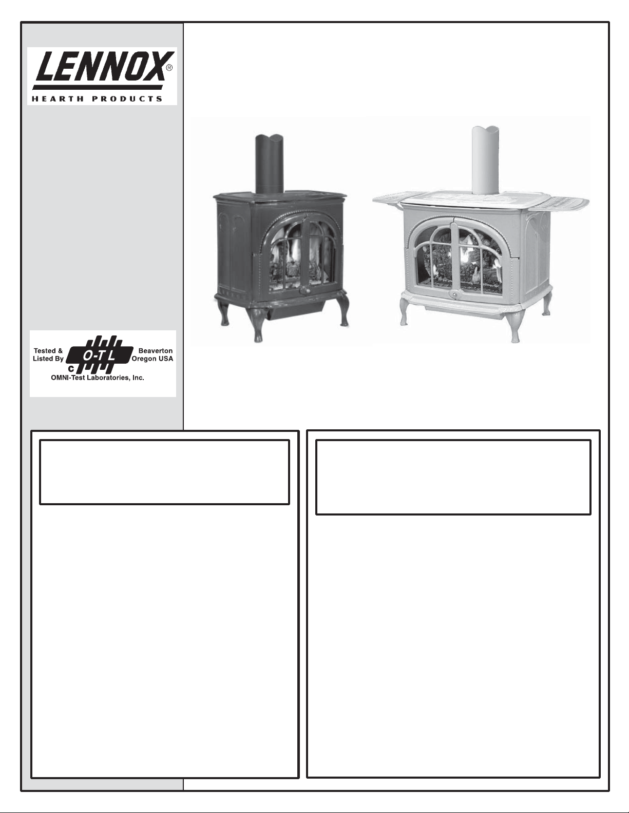
FREESTANDING
VENTED GAS
FIRED ROOM
HEATERS
These appliances may be
installed in an aftermarket
permanently located, manufactured (mobile) home, where not
prohibited by local codes.
INSTALLATION INSTRUCTIONS
MANUAL
Model CI1500DVF Series
Report No. 116-S-08-5
WARNING: IF THE INFORMATION IN THIS MANUAL
IS NOT FOLLOWED EXACTLY, A FIRE OR EXPLOSION MAY RESULT CAUSING PROPERTY DAMAGE,
PERSONAL INJURY OR LOSS OF LIFE.
FOR YOUR SAFETY: Do not store or use gasoline
or other fl ammable vapors or liquids in the vicinity
of this or any other appliance.
FOR YOUR SAFETY: What to do if you smell gas:
• DO NOT light any appliance.
• DO NOT touch any electrical switches.
• Do not use any phone in your building.
• Immediately call your gas supplier from a
neighbor’s phone. Follow your gas suppliers
instructions.
• If your gas supplier cannot be reached, call
the fi re department.
Installation and service must be performed by a
qualifi ed installer, service agency or the gas sup-
.
plier
Serefi na Series Direct Vent Gas Stoves
Model CI2500DVF Series
P/N 775,147M Rev C, 11/04
AVERTISSEMENT: ASSUREZ-VOUS DE BIEN SUIVRE
LES INSTRUCTIONS DONNÉ DANS CETTE NOTICE
POUR RÉDUIRE AU MINIMUM LE RISQUE D’INCENDIE
OU POUR ÉVITER TOUT DOMMAGE MATÉRIEL, TOUTE
BLESSURE OU LA MORT.
POUR VOTRE SÉCURITÉ: Ne pas entreposer ni utiliser
d’essence ni d’autre vapeurs ou liquides infl ammables dans
le voisinage de cet appareil ou de tout autre appareil.
POUR VOTRE SÉCURITÉ: Que faire si vous sentez une
odeur de gaz:
• Ne pas tenter d’allumer d’appareil.
• Ne touchez à aucun interrupteur. Ne pas vous servir
des téléphones se trouvant dans le batiment où vous
vous trouvez.
• Evacuez la piéce, le bâtiment ou la zone.
• Appelez immédiatement votre fournisseur de gaz
depuis un voisin. Suivez les instructions du fournisseur.
• Si vous ne pouvez rejoindre le fournisseur de gaz,
appelez le service dos incendies.
L’installation et service doit être exécuté par un qualifi é
installeur, agence de service ou le fournisseur de gaz.
Page 2

CONGRATULATIONS ON THE PURCHASE OF YOUR NEW GAS APPLIANCE MANUFACTURED BY LENNOX HEARTH PRODUCTS.
When you purchased your new gas fi red heater, you joined the ranks of thousands of
concerned individuals whose answer to their home heating needs refl ects their concern for
aesthetics, effi ciency and our environment. We extend our continued support to help you
achieve the maximum benefi t and enjoyment available from your new gas fi red heater. It
is our goal at Lennox Hearth Products to provide you, our valued customer, with an appliance that will ensure you years of trouble free warmth and pleasure.
Thank you for selecting a Lennox Hearth Products gas fi red heater as the answer to
your home heating needs.
Sincerely,
All of us at Lennox Hearth Products
TABLE OF CONTENTS
Packaging ......................................page 2
Introduction ...................................page 2
General Information .......................page 2
High Altitude ..................................page 3
Location .........................................page 3
Specifi cations .................................page 4
Appliance and Vent Clearances ......page 5
Manufactured Home Requirements ...page 6
Vent Termination Clearances .........page 6
Typical Installation Sequence ........page 8
Step 1 Preparation ...........................page 8
Step 2 Remove Packaging .................page 8
Step 3 Remove Stove From Pallet ....page 8
Step 4 Remove Front Glass ...............page 8
Step 5 Remove Firebox Contents ......page 8
Step 6 Remove Cardboard Pkg. ........page 9
Step 7 Install LP Conv./Options .........page 9
Step 8 Install Lower Access Door .........page 9
Step 9 Install Venting .........................page 9
Step 10 Connect Gas Line ..................page 13
Step 11 Install Log Set .......................page 13
Step 12 Reinstall Front Glass .............page 14
Step 13 Perform Leak Test .................page 14
Step 14 Check Appliance Operation ...page 14
Step 15 Adjust Burner .......................page 15
Step 16 Install Top, Trivet & Ash Lip ..page 16
Rating Plates ....................................... page 17
This installation manual will help you obtain
a safe, effi cient, dependable installation for
your appliance and vent system.
Please read and understand these
instructions before beginning your
installation.
These Millivolt appliances are listed by
OMNI-Test Laboratories Inc. for installation in bedrooms and manufactured
(mobile) homes.
2
PACKAGING LIST
The assembled vented gas stove heater is
packaged with:
one - log set located in fi rebox
one - ember strip located beneath stove
body (on pallet)
one - bag of glowing embers located in
the fi rebox
one - envelope containing the literature
package which consists of the
homeowner's manual, installation
instructions and warranty; located
on the top of the fi rebox
one - cast iron top
one - trivet
one - natural gas to propane conversion kit
one - ash lip
one - lower access door
four - leg levelers
INTRODUCTION
These vented gas heaters are sealed combustion, air circulating gas stoves designed for
residential applications. These appliances
must be installed with "Security Secure
TM
Vent
" or "Simpson Dura Vent" brand vent
systems routed to the outside atmosphere
(other brands may not be used).
Millivolt appliances are designed to operate on natural or propane gas. A millivolt
gas control valve with piezo ignition system
provides safe, effi cient operation. External
electrical power is required to operate the
optional blower if installed on these units.
These appliances comply with National
Safety Standards and are tested and listed
by OMNI-Test Laboratories Inc.; Beaverton,
Oregon (Report No. 116-S-08-05) to ANSI
Z21.88-2002 (in Canada, CSA-2.33-2002),
and CAN/CGA-2.17-M91 in both USA and
Canada, as vented gas heaters.
NOTE: DIAGRAMS & ILLUSTRATIONS NOT TO SCALE.
Installation must conform to local codes. In
the absence of local codes, installation must
comply with the current National Fuel Gas
Code, ANSI Z223.1. (In Canada, the current
CAN-1 B149 installation code.) Electrical
wiring must comply with the National Electrical Code ANSI/ NFPA 70 - latest edition. In
Canada, the current CSA C22-1 Canadian
Electrical Code - latest edition.
DO NOT ATTEMPT TO ALTER OR MODIFY
THE CONSTRUCTION OF THE APPLIANCE OR ITS
COMPONENTS. ANY MODIFICATION OR ALTERATION MAY VOID THE WARRANTY, CERTIFICATION
AND LISTINGS OF THIS UNIT.
GENERAL INFORMATION
Note: Installation and repair should be per-
formed by a qualifi ed service person. The
appliance should be inspected annually by
a qualifi ed professional service technician.
More frequent inspections and cleanings may
be required due to excessive lint from carpeting, bedding material, etc. It is imperative
that the control compartment, burners and
circulating air passage ways of the appliance
be kept clean.
S'assurer que le brùleur et le compartiment
des commandes sont propres. Voir les
instructions d'installation et d'utilisation qui
accompagnent l'appareil.
Provide adequate clearances around air openings and adequate accessibility clearance for
service and proper operation. Never obstruct
the front openings of the appliance.
These appliances are designed to operate
on natural or propane gas only.
These millivolt models come standard with
the manually-modulated gas valve; fl ame
appearance and heat output can be controlled
at the gas valve.
Table 1 shows the BTU input for each
model:
Input (BTU/HR) Manually-Modulated Gas
Valves (millivolt models)
Models Nat. Gas Propane
CI1500DVF
CI2500DVF
17,500 to
28,000
25,500 to
38,500
20,500 to
27,000
26,500 to
34,500
Table 1
Page 3
Tables 2 and 3 show the units' gas pressure
requirements:
Inlet Gas Supply Pressure
(all models)
Fuel # Minimum Maximum
Natural Gas
Propane
4.5" WC
(1.12 kPa)
11.0" WC
(2.73 kPa)
10.5" WC
(2.61 kPa)
13.0" WC
(3.23 kPa)
Table 2
Manifold Gas Supply Pressure
(millivolt models)
Fuel # Low High
Natural
Gas
Propane
(Lo) 1.6" WC
(.40 kPa)
(Lo) 6.3" WC
(1.57 kPa)
(Hi) 3.5" WC
(.87 kPa)
(Hi) 10.0" WC
(2.49 kPa)
Table 3
Installations at Altitudes of 0 to 4500 feet Units are tested and approved for elevations
of 0 to 4500 feet (0 to 1370 meters).
Installations at Altitudes above 4500 ft.For elevations above 4500 feet (1370
meters), install the unit according to the
regulations of the local authorities having
jurisdiction and, in the USA, the latest
edition of the National Fuel Gas Code (ANSI
Z223.1) or, in Canada, the latest edition of
the CAN-B149.1 and CAN-B149.2 codes.
Table 4 shows the units' gas orifi ce size for
the elevations indicated:
Burner Orifi ce Sizes
Model
No.
CI1500DVF .104" .061"
CI2500DVF
Nat.
Gas
.121" .068"
Prop.
Gas
Elevation
Feet
(meters)
0-4500
(0-1372)
0-4500
(0-1372)
Table 4
The millivolt appliances are manually controlled and feature a spark igniter (piezo)
that allows the appliance's pilot gas to be
lit without the use of matches or batteries.
This system provides continued service in
the event of a power outage.
Do not use these appliances if any part
has been under water. Immediately call a
qualifi ed, professional service technician to
inspect the appliance and to replace any parts
of the control system and any gas controls
which have been under water.
Ne pas se servir de cet appareil s'il a été
plongé dans l'eau, complètement ou en
partie. Appeler un technicien qualifi é pour
inspecter l'appareil et remplacer toute partie
du système de contrôle et toute commande
qui ont été plongés dans l'eau.
This appliance may be installed in an
aftermarket permanently located, manufactured home (USA only) or mobile
home, where not prohibited by local codes.
Cet appareil peut être installé dans un
maison préfabriquée (É.-U. seulement) ou
mobile déjà installée à demeure si les
réglements locaux le permettent.
Test gauge connections are provided on
the front of the millivolt gas control valve
(identifi ed IN for the inlet and OUT for the
manifold side).
These appliances and their individual shut-off
valves must be disconnected from the gas
supply piping system during any pressure
testing of that system at pressures in excess
of 1/2 psig (3.5 kPa).
These appliances must be isolated from the
gas supply piping system (by closing their
individual manual shut-off valve) during any
pressure testing of the gas supply piping
system at test pressures equal to or less than
1/2 psig (3.5 kPa).
These appliances must not be connected to
a chimney or fl ue serving a separate solid
fuel burning appliance.
WARNING: This appliance must be properly
connected to a venting system. Operation
of this gas appliance when not connected to
a properly installed and maintained venting
system can result in carbon monoxide (CO)
poisoning and possible death.
Carbon Monoxide Poisoning: Early signs
of carbon monoxide poisoning are similar
to the fl u with headaches, dizziness and/or
nausea. If you have these signs, obtain fresh
air immediately. Turn off the gas supply
to the appliance and have it serviced by
a qualifi ed professional, as it may not be
operating correctly.
WARNING: FAILURE TO COMPLY WITH
THE INSTALLATION AND OPERATING
INSTRUCTIONS PROVIDED IN THIS DOCUMENT WILL RESULT IN AN IMPROPERLY
INSTALLED AND OPERATING APPLIANCE, VOIDING ITS WARRANTY. ANY
CHANGE TO THIS APPLIANCE AND/OR ITS
OPERATING CONTROLS IS DANGEROUS.
IMPROPER INSTALLATION OR USE OF
THIS APPLIANCE CAN CAUSE SERIOUS
INJURY OR DEATH FROM FIRE, BURNS,
EXPLOSION OR CARBON MONOXIDE
POISONING.
NOTE: DIAGRAMS & ILLUSTRATIONS NOT TO SCALE.
WARNING: DO NOT PLACE CLOTHING
OR OTHER FLAMMABLE MATERIALS ON
OR NEAR THIS APPLIANCE.
WARNING: CHILDREN AND ADULTS
SHOULD BE ALERTED TO THE HAZARDS
OF HIGH SURFACE TEMPERATURES. USE
CAUTION AROUND THE APPLIANCE TO
AVOID BURNS OR CLOTHING IGNITION.
YOUNG CHILDREN SHOULD BE CAREFULLY SUPERVISED WHEN THEY ARE IN
THE SAME ROOM AS THE APPLIANCE.
AVERTISSEMENT: SURVEILLER LES
ENFANTS. GARDER LES VÊTEMENTS,
LES MEUBLES, L'ESSENCE OU AUTRES
LIQUIDES À VAPEUR INFLAMMABLES À
COTE DE L'APPAREIL.
LOCATION
In selecting the location, the aesthetic and
functional use of the appliance are primary
concerns. However, vent system routing to
the exterior and access to the fuel supply are
also important. Consideration should be given
to traffi c ways, furniture, draperies, etc., due
to elevated surface temperatures.
Considerations Should Include:
• Existing Chimneys
• Aesthetic Considerations
• Roof Design (Rafter Locations & Roof Pitch)
• Room Traffi c
• Proximity to Combustibles
• Proximity for Optimum Heat Transfer
• Electrical Wiring (if optional blower is
installed)
The installation of this stove will require some
research. Once your options are determined,
consult with your local building department
who will be able to give you the necessary
installation requirements for your area (Is
a building permit required?, Rooms where
installation may not be allowed?, etc.).
3
Page 4
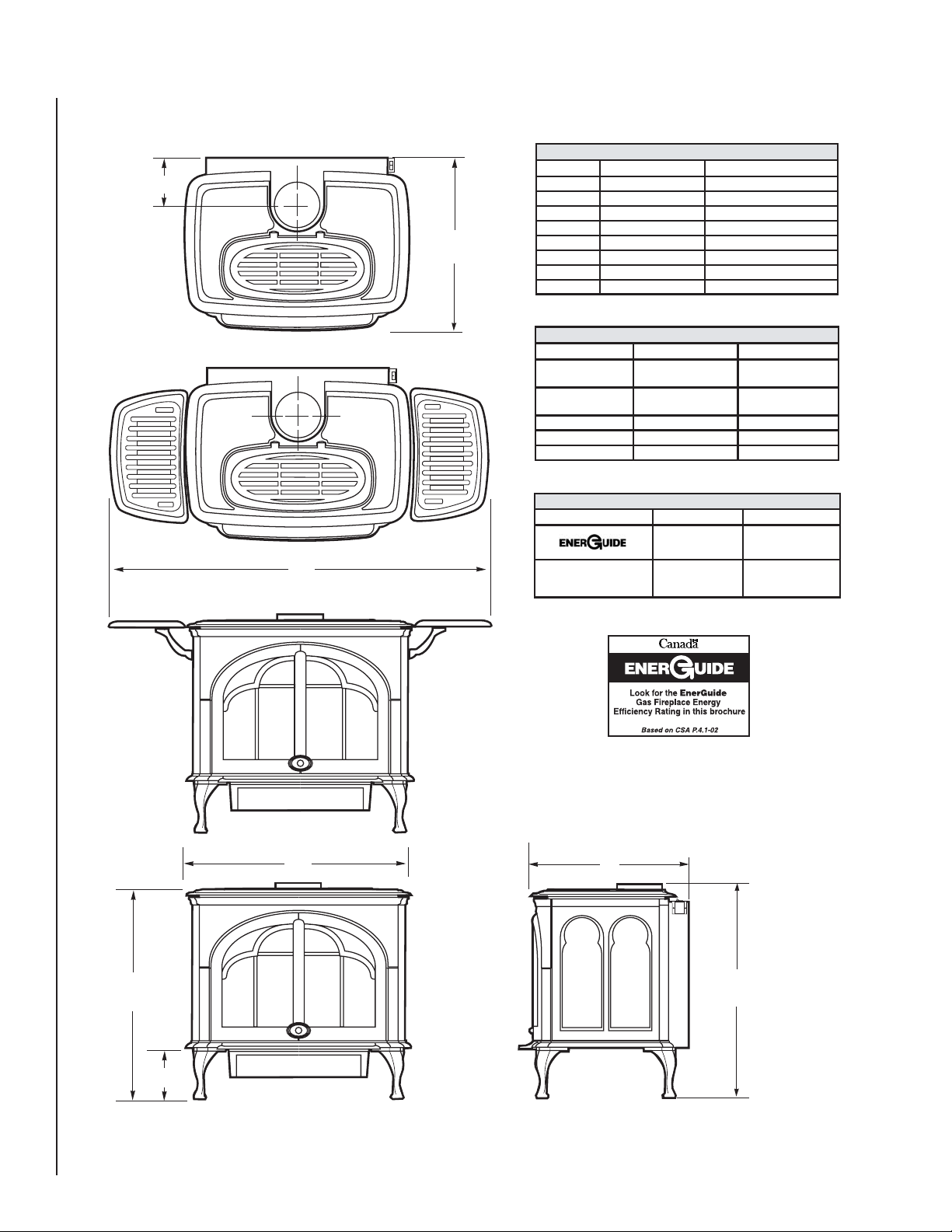
SPECIFICATIONS
F
(with optional warming shelves)
H
E
(with ashlip)
CI1500DVF CI2500DVF
A
B
C
D
E
F
G
H
Min./Max
BTU/hr Input - NG
Min./Max
BTU/hr Input - LP
DV Vent Size
Room Fan CFM
Weight (lb)
Steady State
Efficiency *
24-1/2” (622 mm) 30-1/2” (775 mm)
27-1/2” (699 mm)
19” (483 mm)
20-1/2” (521 mm)
28” (711 mm) 29” (737 mm)
40” (1016 mm)
DIMENSIONS
28-1/2” (724 mm)
7” (178 mm)
23-1/2” (597 mm)
6” (152 mm)
48-1/2” (1232 mm)
SPECIFICATIONS
CI1500DVF CI2500DVF
17,500 / 28,000
20,500 / 27,000
4" inner / 6 5/8" outer
150
206
EFFICIENCIES
CI1500DVF CI2500DVF
67% (NG)
65% (LP)
85% (NG)
87% (LP)
22” (559 mm)
7” (178 mm)
6” (152 mm)
25,500 / 38,500
26,500 / 34,500
4" inner / 6 5/8" outer
150
290
67% (NG)
64% (LP)
83% (NG)
85% (LP)
*Based on maximum vent configuration.
Note: Due to Lennox’ ongoing commitment
to quality , all specifications, ratings
and dimensions are subject to change
without notice.
A
B
C
G
L E N N O X
D
Figure 1
4
NOTE: DIAGRAMS & ILLUSTRATIONS NOT TO SCALE.
Page 5
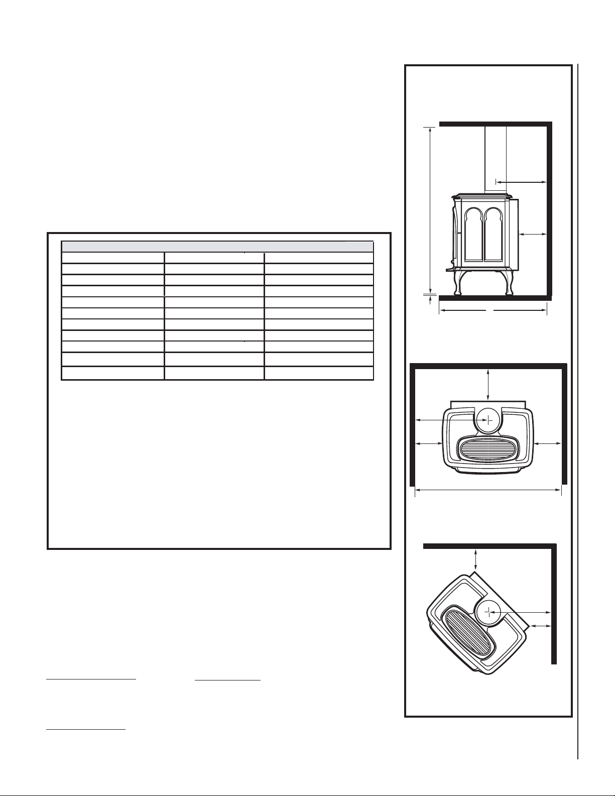
CLEARANCES TO COMBUSTIBLE MATERIALS / FLOOR PROTECTION
• The location should also be free of electrical, plumbing or other heating/air conditioning
ducting.
• Due to high temperatures, this appliance should be located out of traffi c and away from
furniture, draperies and not in windy or drafty areas.
• This appliance can be installed in most residential room confi gurations, parallel to a rear
or adjacent wall, or in an alcove that allows for the minimum clearances to combustible
surfaces. Your local building inspector should review your plans prior to installation.
• When installing this appliance, provide adequate clearances for the purposes of servicing
and proper operation.
• As determined through the safety certifi cation of this unit, a minimum clearance to
combustible materials must be maintained around specifi c areas of the gas appliance. (See
Table 5 & Figure 2)
CLEARANCES
CI2500DVF
*10” (254 mm)
*17-1/4” (438 mm)
*19” (483 mm)
4” (102 mm)
2” (51 mm)
4” (102 mm)
0” (0 mm)
***62” (1575 mm)
**34 1/2” (876 mm)
48” (1219 mm)
A (minimum)
B (minimum)
C (minimum)
D (minimum)
E (minimum)
F (minimum)
G (minimum)
H (minimum)
I (minimum)
J (MAXIMUM)
CI1500DVF
*10” (254 mm)
*14-1/4” (362 mm)
*15-7/8” (403 mm)
4” (102 mm)
2” (51 mm)
4” (102 mm)
0” (0 mm)
***62” (1575 mm)
**28 1/2” (724 mm)
48” (1219 mm)
Table 5
Clearance To Combustibles
& Alcove Dimensions
Side View / Rear Wall or Alcove Clearances
*A
H
D
L E N N O X
G
J
Top View / Rear Wall or Alcove Clearances
D
* Dimensions with a single asterix are reference dimensions only.
** If the optional warming shelves are installed, a greater alcove width is
required as follows:
CI1500DVF - 44" (1118 mm) min.
CI2500DVF - 52 1/2" (1334 mm) min.
***This includes any projections such as shelves, windowsills, mantels, etc.
above the appliance.
Note: Recommended clearance zone from the front of the appliance to combustibles is 36 inches (914 mm) minimum
.
Floor Protection
When installed directly on carpeting, tile (see Note below) or other combustible material
other than wood fl ooring, the appliance shall be installed on a metal or wood panel extending the full width and depth of the stove body.
Note: Ceramic tile is non-combustible and does not require a wood or metal panel under
the appliance.
Vent Clearances - All Models
For Horizontal Sections:
Top - 3" (76.2 mm) min.
Sides - 1" (25.4 mm) min.
Bottom - 1" (25.4 mm) min.
At Wall Firestops:
Top - 3" (76.2 mm) min.
Sides - 1" (25.4 mm) min.
Bottom - 1/2" (12.7 mm) min.
*B
EE
I
Top View / Corner Clearances
F
*C
F
Figure 2
For Vertical Sections:
Sides - 1" (25.4 mm) min.
NOTE: DIAGRAMS & ILLUSTRATIONS NOT TO SCALE.
5
Page 6
MANUFACTURED (MOBILE) HOME
REQUIREMENTS
These models may be installed in an aftermarket permanently located, manufactured
home, where not prohibited by local codes.
When installed in Manufactured Housing
the following supplemental requirements
must be met:
• The appliance must be secured to the fl oor
(i.e. use (4) ¼” x 2 ¾” bolts and nuts or
equivalent. Note: Not included) for securing
appliance to the manufactured home fl oor.
• The appliance must be grounded to the
chassis of the manufactured home. Use a
No. 8 or heavier copper wire at least 18” in
length.
• The structural integrity of the manufactured
home fl oor, walls, ceiling and roof must be
maintained.
• A manufactured (mobile) home installation
must conform with the Manufactured Home
Construction and Safety Standard, Title 24
CFR, Part 3280, or, when such a stan-dard
is not applicable, the Standard for Manufactured Home Installations, ANSI / NCSBCS
A225.1, or standard for Gas equipped
Recreational Vehicles and Mobile Housing,
CSA Z240.4.
QUESTIONS TO ASK LOCAL BUILDING
OFFICIAL
This appliance must be installed per manufacturers’ instructions.
Installations must conform to appropriate
local codes and applicable state and federal
requirements. Familiarity with these requirements before installation is essential. Some
important considerations to discuss with
local building offi cials include:
1. Applicable codes (i.e. Uniform Mechanical
Code, State or Regional Gas Codes, National
Fuel Gas Code)
2. Local amendments
3. Recognized testing lab: OMNI-Test Laboratories Inc.; Beaverton, Oregon
4. Is a permit required - cost?
5. In some states or municipalities, a licensed
gas fi tter or plumber may be required to
install this appliance. Check with your local
building offi cial for requirements in your area
(i.e. Is a license required for installation of
gas supply line)?
6. Maximum amount of gas pipe without a
pressure test - type of test required?
7. Are below grade penetrations of the gas line
allowed?
8. Is concealed gas piping allowed?
9. Specifi c requirements of concealed fi ttings?
10. I s rigid pipe to appliance required?
11. Allowed piping materials?
12. Shut-off valve required within 4 feet of the
fi rebox?
13. M ay the shut-off valve be concealed?
14. Rooms where the installation is not
allowed?
In the absence of local codes, installation
should conform to National Fuel Gas Code,
ANSI Z223.1 / NFPA 54-Latest Edition in the
USA or National Fuel Gas Code, CAN/CGAB149-Latest Edition in Canada.
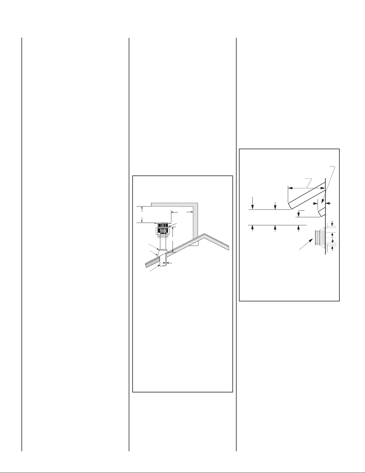
VENT TERMINATION CLEARANCES
Vertical Vent Termination Clearances
TERMINATION HEIGHTS FOR VENTS ABOVE
Horizontal Overhang
2 FT MIN.
Termination
Storm Collar
Flashing
Concentric
Vent Pipe
FLAT OR SLOPED ROOFS
Vent
2 FT
MIN.
Lowest
Discharge
Opening
H*
1 inch (25.4 mm) Minimum
Clearance to Combustibles
*H = MINIMUM HEIGHT FROM ROOF TO
LOWEST DISCHARGE OPENING OF VENT
Vertical
Wall
X
12
Roof Pitch is X/12
The vent/air intake termination clearances
above the high side of an angled roof is as
follows:
Roof Pitch ................. Feet Meters
Flat to 6/12 ................1.0 0.3
6/12 to 7/12 ............... 1.25 0.38
7/12 to 8/12 ............... 1.5 0.46
8/12 to 9/12 ............... 2.0 0.61
9/12 to 10/12 ............. 2.5 0.76
10/12 to 11/12 ........... 3.25 0.99
11/12 to 12/12 ........... 4.0 1.22
12/12 to 14/12 ........... 5.0 1.52
14/12 to 16/12 ........... 6.0 1.83
16/12 to 18/12 ........... 7.0 2.13
18/12 to 20/12 ........... 7.5 2.29
21/12 to 21/12 ........... 8.0 2.44
Figure 3
These instructions should be used as a
guideline and do not supersede local codes in
any way. Install vent according to local codes,
these instructions, the current National Fuel
Gas Code (ANSI-Z223.1) in the USA or the
current standards of CAN/CGA-B149.1 and
-B149.2 in Canada.
Horizontal Vent Termination Clearances
The horizontal vent termination must have
a minimum of 3" (76 mm) clearance to any
overhead combustible projection of 2 1/2" (64
mm) or less. See Figure 4. For projections
exceeding 2 1/2" (64 mm), For additional vent
location restrictions refer to Figure 5.
Horizontal Vent Termination Clearances
Combustible Projection
2 1/2 inches or less in length
Combustible Projection
greater than 2 1/2 inches in length
Ventilated
Soffit
Unventilated
Soffit
3"
18"
(457 mm)
Note - See vent manufacturer's instructions for recess
allowances, into exterior walls for the horizontal termination caps.
12"
(305 mm)
Horizontal T
Figure 4
(76 mm)
ermination Kit
Side Elevation View
(76 m
1"
3"
6
NOTE: DIAGRAMS & ILLUSTRATIONS NOT TO SCALE.
Page 7

EXTERIOR HORIZONTAL VENT TERMINATION CLEARANCE REQUIREMENTS
* See Item D in the Text Below.
Exterior Wall
*18”
Horizontal
Termination
Inside Corner
B
V
L
X
= Air Supply Inlet
.denepo
ecnailpparehto
ynoclab
.sgnillewdhtob
.ynoclabro,kced
18”
Detail D
lanimretehtfoenil
Center Line
of Termination
Inside
Corner Detail
G
Ventilated Soffit
V
Fixed
Closed
Window
V
F
V
C
A
V
= Vent Terminal = Area where Terminal is not Permitted
C
C
C
,hcrop,adnarev,edargevobaecnaraelC=A
ebyamtahtroodrowodniwotecnaraelC=B
V
A
= 9” in U.S.
A
= 12” in Canada
B
Operable
V
Window
B
B
B
A
J
*)mc03(sehcni21**)mc03(sehcni21
secnailpparof)mc51(ni6
wodniwdesolcyltnenamrepotecnaraelC=C tneverpotdednemmocer)mm503("21
noitasnednocwodniw
tiffosdetalitnevotecnaraelclacitreV=D
)mm854("81)mm854("81
latnozirohanihtiwlanimretehtevobadetacol
retnecehtmorf)mm854(sehcni81foecnatsid
tiffosdetalitnevnuotecnaraelC=E)mm503("21)mm503("21
renrocedistuootecnaraelC=Fmuminim)mc7.21("5muminim)mc7.21("5
renrocedisniotecnaraelC=Gmuminim)mc2.51("6muminim)mc2.51("6
enilretnecfoedisnihcaeotecnaraelC=H
ylbmessarotaluger/retemevobadednetxe
teltuotnevrotalugerecivresotecnaraelC=I*)mc19(teef3**)mc19(teef3
telniylppusrialacinahcemnonotecnaraelC=J
secnailpparof)mc51(ni6
ynaottelnirianoitsubmocehtrognidliubot
telniylppusrialacinahcemaotecnaraelC=K 6 feet (1.8m)* )m3(teef01nihtiwfievoba)mc19(teef3
devaproklawedisdevapevobaecnaraelC=L
‡)m31.2(teef7‡)m31.2(teef7
ytreporpcilbupnodetacolyawevid
rokced,hcrop,adnarevrednuecnaraelC=M
‡*)mc03(sehcni21‡)mc03(sehcni21
3 ft.
X
A
3 ft.
*noitallatsnInaidanaC**noitallatsnISU
)mc03(ni21,)Wk3(hutB000,01<
dna)Wk3(hutB000,01>secnailpparof
)mc19(sehcni63,)Wk03(hutB000,001<
*)Wk03(hutB000,001>secnailpparof
teef51fothgiehanihtiw)mc19(teef3
*ylbmessarotaluger/retemehtevoba
)mc03(ni21,)Wk3(hutB000,01<
dna)Wk3(hutB000,01>secnailpparof
)mc19(sehcni63,)Wk03(hutB000,001<
*)Wk03(hutB000,001>secnailpparof
.edoCnoitallatsnIenaporPd B149.2 nAsaGlanoitaN1.941B-ASCtnerrucehthtiwecnadroccanI*
.sedoCsaGleuFlanoitaN45APFN/1.322ZSISNAtnerucehthtiwecnadroccanI**
:roolfehthtaenebsedis2muminimanonepoyllufsiynoclabrokced,hcrop,adnarevfidettimrepylnO‡*
H
E
D
V
M
V
I
secnailpparof)mc51(ni6
)mc32(ni9,)Wk3(hutB000,01<
dna)Wk3(hutB000,01>secnailpparof
)mc03(sehcni21,)Wk51(hutB000,05<
**)Wk51(hutB000,05>secnailpparof
tneverpotdednemmocer)mm922("9
noitasnednocwodniw
teef51fothgiehanihtiw)mc19(teef3
**ylbmessarotaluger/retemehtevoba
secnailpparof)mc51(ni6
)mc32(ni9,)Wk3(hutB000,01<
dna)Wk3(hutB000,01>secnailpparof
)mc03(sehcni21,)Wk51(hutB000,05<
**)Wk51(hutB000,05>secnailpparof
**yllatnoziroh
sevresdnasgnillewdylimafelgnisowtneewtebdetacolsihcihwyawevirddevaproklawedisaevobayltceridetanimrettonllahstnevA‡
Figure 5
NOTE: DIAGRAMS & ILLUSTRATIONS NOT TO SCALE.
7
Page 8

TYPICAL INSTALLATION SEQUENCE
See the page numbers references in the
following steps for detailed procedures.
The typical sequence of installation follows,
however, each installation is unique resulting
in variations to those described.
Step 1. (page 8) Preparation - Plan and install
gas line, venting system and fl oor protection
(if necessary).
Step 2. (page 8) Remove outer carton. Remove
inner packages and packing materials and
set aside.
Step 3. (page 8) Remove stove from pallet
and place into positioned where unit is to be
installed.
Step 4. (page 8) Remove front glass enclosure
from stove and set aside.
Step 5. (page 8) Remove packaged materials
from inside fi rebox and set aside (log set, bag
of embers and NG to LP conversion kit).
Step 6. (page 9) Remove cardboard packaging material from beneath relief door and
discard.
Step 7. (page 9) Install LP Conversion kit (if
necessary). Install any optional accessories
(excluding fi rescreens).
Step 8. (page 9) Install lower access door.
Step 9. (page 9) Venting System Installation.
Step 10. (page 13) Connect gas supply line
to the appliance. Purge Air.
Step 11. (page 13) Install log set, ember strip
and embers.
Step 12. (page 14) Reinstall front glass
enclosure.
Step 13. (page 14) Test all connections for
leaks (factory and fi eld).
Step 14. (page 14) Check appliance for proper
operation.
Step 15. (page 15) Adjust burner to ensure
proper fl ame appearance.
Step 16. (page 16) Install stove top, trivet
and ash lip.
DETAILED INSTALLATION STEPS
Step 1: PREPARATION - Plan and install gas
line and fl oor protection (if necessary - see Floor
Protection, page 5).
Gas Supply Line (reference Figure 18 on page
13) - Installing a gas supply line from the
fuel supply to the appliance involves numerous considerations of materials, protection,
sizing, locations, controls, pressure, sediment,
and more. Certainly no one unfamiliar and
unqualifi ed should attempt sizing or installing
gas piping.
The gas supply line should be plumbed from
the fuel source to the area where the appliance
is to be installed per requirements outlined
in NFPA 54 - latest edition (USA) and B149
- latest edition (Canada).
8
The proper gas line diameter must be used
to run from the supply regulator (at the gas
company meter) to the appliance. Never use
galvanized or plastic pipe. Refer to table 6
for suggested sizing of the gas supply line if
black iron pipe is being used.
The gas supply line should be connected to
the appliance at step 10.
Suggested Sizing of Black Iron Pipe
Schedule 40 - Pipe Supply Line
Schedule 40 Pipe
Schedule 40 Pipe
Length (Feet)
0-10 1/2 3/8
10-40 1/2 1/2
40-100 1/2 1/2
100-150 3/4 1/2
150-200 3/4 1/2
Table 6
IMPORTANT NOTE: If propane is used, be aware
that if the tank size is too small (i.e. under
100-lbs, if this is the only gas appliance in the
dwelling. Ref. NPFA 58), there may be loss of
pressure, resulting in insuffi cient fuel delivery
(which can result in sooting or other malfunctions). Any damage resulting from an improper
installation, such as this, is not covered under
the limited warranty.
Inside Diameter (Inches)
Natural
Gas
Propane
Gas
Step 2: REMOVE PACKAGING - Remove the
large outer carton. Remove all the inner packages and packing materials and set aside. To
remove the ember strip package below the
stove body, carefully cut the 2 plastic ties
using scissors.
Step 3: REMOVE FROM PALLET -
A. Remove the trivet, then the cast iron stove top
by carefully lifting them up and off and setting
them aside (READ CAUTION BELOW).
CAUTION: THE CAST IRON STOVE TOP IS VERY
HEAVY AND MAY REQUIRE A MINIMUM OF
TWO PEOPLE TO LIFT; ONE PERSON ON EACH
SIDE (THE CI1500 SERIES CAST TOP WEIGHS
~20 POUNDS AND THE CI2500 SERIES CAST
TOP WEIGHS ~40 POUNDS).
B. Remove stove body from pallet (READ
CAUTION BELOW).
CAUTION: THE STOVE BODY IS VERY HEAVY.
THE USE OF A HEAVY DUTY ESCALARA
(STAIR STEP HAND TRUCK) IS RECOMMENDED FOR LIFTING THE STOVE BODY.
Remove the screws and support plate which
secure the stove legs to the pallet. Lift stove
off of the pallet and place it into position
(where unit is to be installed).
NOTE: DIAGRAMS & ILLUSTRATIONS NOT TO SCALE.
Note: Install Leg Leveling Bolts if Necessary:
The four leg leveling bolts (included in literature
package), are provided for leveling the stove if
necessary. To install, thread the bolts into the
existing holes in the bottom of each leg. Turn the
leveling bolts to adjust for correct height.
Step 4: REMOVE FRONT GLASS ENCLOSURE PANEL - Remove the front glass
enclosure from stove as follows:
WARNING: HANDLE GLASS WITH EXTREME
CARE! THE GLASS PANEL IS SUSCEPTIBLE
TO DAMAGE — DO NOT SCRATCH WHILE
HANDLING OR WHILE REINSTALLING THE
GLASS ENCLOSURE PANEL.
WARNING: NEVER OPERATE APPLIANCE
WITHOUT THE FRONT GLASS ENCLOSURE
PANEL IN PLACE AND SECURE.
A. Locate and open the 2 latches below the
stove body (See Figure 6).
Open both Latches as shown.
Figure 6
B. Reach under the bottom front of the front
glass enclosure and pull it forward as shown
in Figure 7.
Figure 7
C. Lift glass assembly up and out and carefully
set aside in a safe place (see Figure 8).
Figure 8
Page 9

Step 5: REMOVE MATERIALS FROM FIRE-
BOX - Remove the packaged materials from
inside of the fi rebox and set aside (propane
conversion kit, log support cartons, log set
and embers).
Step 6: REMOVE CARDBOARD - Remove the
cardboard packaging material from beneath
the relief door and discard (see Figure 9).
Remove Cardboard
RELIEF DOOR
Blower
Mounting
Bracket
Blower Wiring Diagram
Power Cord
Blower
Assembly
(Shown
Rotated 90
Degrees CCW)
Step 8: INSTALL LOWER ACCESS DOOR .
Install the lower access door by inserting the
tabs on the door sides into the corresponding
holes on the brackets on the stove bottom
(see Figure 12 below)
The lower access
door hinges open
to access Valve
Controls
Lower Access
Door
Figure 12
Figure 9
Step 7: INSTALL LP CONVERSION KIT (IF
NECESSARY) AND OPTIONAL ACCESSORIES
- Install the LP conversion kit and optional
accessories per instructions provided with
the kits (do not install an optional fi rescreen
or brick liner kit at this point).
A. Optional accessories include a wall ther-
mostat, blower kit, brick liner kit, warming
shelves and a standard or deluxe remote
control kits.
B. If a wall-mounted thermostat is selected,
mount it in a convenient location on a wall
near the stove. If the warming shelves are
being installed, see Homeowners Manual for
installation instructions.
C. Wire the thermostat within the millivolt control
circuit using a maximum of 25 feet of 18 gage,
2 conductor wire. Caution: Do not connect the
optional wall thermostat, gas control valve or
control wiring system of the unit to a 120 volt
power supply (residential line voltage)
The gas valve is set in place and pre-wired at the
factory on both models (see Figure 11).
SIT Millivolt Wiring Diagram
If any of the original wire as supplied must be replaced,
it must be replaced with Type AWM105°C – 18 GA. wire.
TH
TP
TH
OR REMOTE
* SWITCH
Figure 10
TP
Thermopile
* ON/OFF SWITCH, OPTIONAL
THERMOSTAT
CONTROL RECEIVER
Wiring - Optional Forced Air Blower Kit:
BK-CI (see Figure 11 for wiring diagram) - (An
optional fi eld-provided outletbox/J-Box may
also be used). Install the blower kit according
to the installation instructions provided with
the kit.
Black
White
Fan Disc
White
Black
Black
Rheostat
Figure 11
IMPORTANT: Ground supply wire must be
connected to the green wire attached to
the green ground screw. Failure to do so
will result in a potential safety hazard. The
appliance must be electrically grounded
in accordance with local codes or, in the
absence of local codes, the National Electrical Code, ANSI/NFPA 70 - latest edition.
In Canada, the current CSA C22-1 Canadian
Electrical - latest edition.
WARNING: THE POWER CORD MUST BE
PLUGGED DIRECTLY INTO A PROPERLY
GROUNDED THREE-PRONG 120 VOLT, 60 HZ
WALL RECEPTACLE. Do not cut or remove
the grounding prong from this plug. Do
not route power cord under or in front of
appliance.
NOTE: DIAGRAMS & ILLUSTRATIONS NOT TO SCALE.
Step 9: VENTING SYSTEM INSTALLATION
INSTALL VENTING COMPONENTS PER
VENT MANUFACTURERS INSTRUCTIONS
The vent system may not service multiple
appliances, and must never be connected to a
fl ue serving a solid fuel burning appliance.
CAUTION: Under no circumstances should
these appliances be vented to other rooms
or buildings. These appliances must only be
vented to the outside. Vent terminations shall
not be recessed into a wall or siding.
IMPORTANT: Do not exceed the maximum
horizontal run allowed (see Figure 13 &
14).
Support Brackets - Install vent support brackets as specifi ed in the vent manufacturers
instructions and the National Gas Fuel Code,
USA - NFPA 54 / ANSI Z223.1, 7.6.5 Support
of Gas Vents. Gas vents shall be supported and
spaced in accordance with their listings and
the (vent) manufacturer instructions.
General Information: These instructions
should be used as a guideline and do not
supersede local codes in any way. Install vent
according to local codes, these instructions,
the current National Fuel Gas Code (NFPA
54 / ANSI-Z223.1) in the USA or the current
standards of CAN/CGA-B149.1 and -B149.2
in Canada.
These stoves are designed, tested and listed
for operation and installation with, and only
with, "Security Secure Vent
TM
" or "Simpson
Dura Vent" brand Components (co-axial DV
pipe with 4" inner & 6 5/8" outer diameter).
These approved vent system components are
labeled for identifi cation. DO NOT use any other
manufacturer's vent components with these
appliances. These stoves must be vented directly
to the outside.
9
Page 10

Horizontal Termination
Vertical Termination
The vent must rise vertically, a minimum of 24" (610 mm) off the
top of the appliance for Natural Gas and 36" for Propane Gas before
the fi rst elbow.
The horizontal run may extend up to 20 feet ( 6 meters) and include
a vertical rise of up to 40 feet (12 meters) - see Figure 13. Horizontal
termination must meet the criteria shown in Figures 4 and 5.
• Approved vent systems must terminate above and including the
heavy line in Figure 13.
• Two 45 degree elbows may be substituted for each single 90 degree
elbow.
• With a rise between 2 feet to 5 feet, one 90 degree or two 45 degree
elbows may be used.
40
39
38
37
36
35
34
33
32
31
30
29
28
27
26
25
24
23
22
21
20
19
18
Vertical Run (in feet)
17
16
15
14
13
12
11
Measure from the appliance fl ue collar to the top of the vent pipe
10
10
9
8
7
6
5
One 90
4
degree
3
elbow
2
1
0
3
2
1
Figure 13
May use up to three 90
degree elbows
11
89
10
67
5
4
Horizontal Run (in feet)
Unacceptable
Venting
Confi guration
13 14
12
15 16 17
18 19
20
A vertical vent system must terminate no less than 8 feet ( 2.44 meters)
and no more than 40 feet / 12 meters ( above the appliance fl ue collar.
See Figure 14.
A vertically terminated vent system must also conform to the following criteria:
No more than three 90 degree elbows may be used.
Two 45 degree elbows may be substituted for one 90 degree elbow. No
more than six 45 degree elbows may be used.
Vent must rise a minimum of 2 feet before an offset is used.
Termination height must conform to roof clearance as specifi ed in
Figure 3
40
39
38
37
36
35
34
33
32
31
Vertical Terminations Must
30
be in this area
29
28
27
26
25
24
23
22
21
20
19
Vertical Run (in feet)
18
17
16
15
14
13
12
Measure from the appliance fl ue collar to the top of the vent pipe
11
10
10
9
8
7
6
5
4
3
2
1
0
3
4
2
1
Figure 14
56789
Horizontal Run (in feet)
11
10
Unacceptable
Venting
Confi guration
13 14
15 16 17
12
18 19
20
10
NOTE: DIAGRAMS & ILLUSTRATIONS NOT TO SCALE.
Page 11

Installing Support Brackets
Direct Vent Retrofi t Of Existing Chimney System
Install support brackets per vent manufacturers instructions.
Vertical Vent Installation
Support Bracket Placement Diagram
Support
Brackets
Placement:
Horizontal Runs - Requires
1 inch
minimum
a support bracket every 5
feet (152 cm).
8 feet
Vertical Runs - Requires
support brackets every 8
feet (244 cm) above the
stove vent outlet..
Figure 15
Wall
Stud
An existing Class-A (wood-burning) Metal Chimney or Masonry
Chimney can be converted to a direct vent system. Use one of the
following chimney conversion kits listed below. Have the existing
chimney system inspected by a professional prior to the conversion.
If using Simpson Dura-Vent brand liner kit, see “IMPORTANT” note
at the top of page 12. The chimney conversion should not be applied
to the portion of the vent system that is in the room of the appliance.
Use only Co-Axial direct vent pipe (4” inner pipe, 6 5/8” outer pipe
as listed on page 12) from the appliance to the retro-connector into
converted fl ue system. Adhere to all specifi cations outlined in this
manual regarding clearances to combustibles, vertical and horizontal
vent length minimums and maximums, etc. Read all instructions in
this manual and provided by vent manufacturer with kit carefully before
starting the installation. Failure to follow the instructions may create
a fi re or other safety hazard, and will void the warranty. The following
Vent System components may be safely used with this appliance.
Chimney DV Liner Kits
Model
SV4MCK
SV4CCK1
SV4CCK2
Brand: SECURITY SECURE VENT / Description
Masonry Chimney Conversion Kit –Vertical term. Cap, cap adapter,
masonry cover, black adapter (to flex), 2 gear clamps
Factory Built Chimney Conversion Kit – for 6” I.D., 1” insulation.
Factory Built Chimney Conversion Kit – for 7” I.D., 1” insulation; 8”
I.D., 1” insulation; 6” I.D., 2” insulation.
SV4CCK3 Factory Built Chimney Conversion Kit – for 10” I.D., 1”
Model
insulation; 7” I.D., 2” insulation; 8” I.D., 2” insul
Brand: SIMPSON DURA-VENT / Description
tion.
a
934 Masonry Chimney Conversion Kit
931 Factory Built Chimney Conversion Kit A – for 6” I.D.;
932
933
Factory Built Chimney Conversion Kit B – for 6”, 7” & 8” I.D.
Factory Built Chimney Conversion Kit C – for 7” & 8” I.D.
Table 7
Building
Brackets
Support
Framing
Elbow
Ceiling
Vertical
Rise
Figure 16
Support
Horizontal Vent Installation
Support Bracket Placement Diagram
Horizontal / Inclined Run
(¹⁄₄" Rise per Foot of Horizontal Run in the
Direction away from the Stove)
Vent Sections
Firestop/Spacer
See figure for
vertical vent
section support.
Support Bracket Spacing
Every 5 ft (1.52 m)
NOTE: DIAGRAMS & ILLUSTRATIONS NOT TO SCALE.
Termination
Shown
Exterior
Wall
Select Venting System - Horizontal Or Vertical
The following sections describe vertical (roof) and horizontal
(exterior wall) vent applications. Refer to the section relating to
your installation. A list of approved venting components is shown
on page 11 & 12.
Vertical
Horizontal
Combustion
Air
Exhaust
Figure 17
11
Page 12

DIRECT VENT SYSTEM COMPONENTS
The following "Security Secure Vent
TM
" or "Simpson Dura-Vent" brand Direct-Vent components may be safely used with these appliances.
IMPORTANT NOTE: Seal the fi rst section of pipe to the stove collar using mill-pac black, high temperature sealant.
Model # SECURITY SECURE-VENT - Description
N/A N/A 970 Basic Horizontal Term. Kit (90 Deg. Black Elbow,
N/A N/A 971 Horizontal Term. Kit A (90 Deg. Black Elbow, Wall
SV4FK Vertical Flat Roof Term. Kit (w/flashing, storm collar,
vertical Term. Cap)
SV4FAK Vertical pitched Roof Kit, 1/12-7/12 (with adjustable
roof flashing, storm collar, vertical termination cap)
SV 4F BK Vertical pitched Roof Kit, 8/12-12/12 (with adjustable
roof flashing, storm collar, vertical termination cap)
SV4L6 6 Pipe Length (Galvanized) 908 6 P ip e L en gt h ( Ga lv an iz ed )
S V4LB 6 6 P ip e L en gt h ( Bl ac k) 908B 6 P ip e L en gt h ( Bl ac k)
N /A N/A 907B 9 P ip e L en gt h ( Bl ac k)
SV4L12 12 Pipe Length (Galvanized) 906 12 P ip e L engt h (Galvanized)
S V4LB 1 2 12 P ip e L en gt h ( Bl ac k) 906B 12 Pi pe Le ng th (B la ck )
SV4L24 24 Pipe Length (Galvanized) 904 24 P ip e L engt h (Galvanized)
S V4LB 2 4 24 P ip e L en gt h ( Bl ac k) 904B 24 Pi pe Le ng th (B la ck )
SV4L36 36 Pipe Length (Galvanized) 903 36 P ip e L engt h (Galvanized)
S V4LB 3 6 36 P ip e L en gt h ( Bl ac k) 903B 36 Pi pe Le ng th (B la ck )
SV4L48 48 Pipe Length (Galvanized) 902 48 P ip e L engt h (Galvanized)
S V4LB 4 8 48 P ip e L en gt h ( Bl ac k) 902B 48 Pi pe Le ng th (B la ck )
S V4LA 6 Ad j. Pi pe Le ng th , ( Ga lv an iz ed) 908 6 A dj . P ip e L en gt h, (G al va ni zed)
SV4LB A 6 Adj. Pipe L ength (Black) N/A N/A
SV4LA 12 12 Adj. Pipe Length, (Galvanized) 911 11 - 14 5/ 8 A dj . P ip e L en gt h ( Ga lv an iz ed )
SV4LB A12 12 Adj. Pipe Length, (Black) 911B 11 -1 4 5 /8 Adj. Pipe Length (Black )
S V4E 45 45 Deg. Elbo w, Swiv el (G al va ni ze d) 945G 45 D eg . E lb ow, S wivel (Galvanized)
S V4E B 4 5 4 5 D eg . E lbow, Swivel (Black ) 945BG 4 5 D eg . E lbow, S wivel (Black )
S V4E 90 90 Deg. Elbo w, Swiv el (G al va ni ze d) 990G 90 D eg . E lb ow, S wivel (Galvanized)
S V4E B 9 0 9 0 D eg . E lbow, Swivel (Black ) 990BG 9 0 D eg . E lbow, S wivel (Black )
S V4E9 0 90 Deg. E lbow (G al vani ze d) 990 90 Deg. Elbow (Galvanized)
S V4EB 9 0 90 D eg . E lbow (Black). 990B 90 Deg. Elbow (Black)
SV4CHC-1 Horizontal Standard Term. Cap 984 Hor iz ontal St andard Term. Cap
N/A N/A 991 Vertical Hi gh Wind Te rm . C ap
SV4CG V Vertical Termination Cap N/A N/A
S V4ST C 3 6 Sno rk el Termination C ap 36 981 S no rk el Te rm in at io n C ap 36
S V4ST C 1 4 Sno rk el Termination C ap 14 982 S no rk el Te rm in at io n C ap 14
S V4VS Vin yl Sh ie ld Pr ot ec to r 950 Vinyl Siding Standoff
S V4SF Ro un d C ei li ng Su pp or t / Wa ll Th im bl e C ov er 940 Round Ceiling Support / Wall T himble Cover
SV4CS B Cathedral Ceiling Support Box, decorative square 941 Cathedral Ceiling Support Box
SV4PF Black Plate, Decorative, Square N/A N/A
SV4SU Universal Support 942 Round Ceiling Support Box/Wall Thimble
SV4FC Storm Collar 953 Storm Collar
SV4RS M Wall Radiation Shield N/A N/A
SV4BF Firestop 963 Firestop Spacer
SV4F Flashing, Flat Roof (storm collar included) N/A N/A
SV4FA Flashing, Adjustable roof 1/12-7/12 (storm collar
included)
SV4FB Flashing, Adjustable 8/12-12/12 (storm collar included) 943S Flashi ng 7/ 12 -1 2/ 12
S V4B M Wall Band (Strap) 988 Wa ll Strap
Model # SIMPSON DURA-VENT Description
Wall Thimble Cover, Horizontal Square Term. Cap)
Thimble Cover, Horizontal Square Term. Cap, adj.
24 black pipe, 11-14 5/8 ad j. black pipe)
973 Vertical Termination Kit (990B, 940, 984)
978 Vertical Pitched Roof Kit, 0/12 6/1 2 (with
adjustable flashing, storm collar, low profile term.
Cap)
N/A N/A
943 Fla sh in g 0/ 12 -6 /1 2
Note: Snorkel Caps: These are elongate vent termination caps, which incorporate the principles of natural draft into a horizontal installation. Two styles
are common, 14” and 36” (Cap height). They enhance draft and relieve back-pressure by creating natural draft in the snorkel.
Table 8
12
NOTE: DIAGRAMS & ILLUSTRATIONS NOT TO SCALE.
Page 13

Step 10. CONNECTING GAS LINE
Gas
Valve
3"
Min
*Sediment Trap
*A Sediment Trap is recommended to prevent moisture
and debris in gas line from
damaging the valve.
.
3/8" Nipple
3/8" Union
3/8" Close Nipple
Figure 18 - GAS CONNECTION
Make gas line connections. All codes require a
shut-off valve mounted in the supply line. Figure
18 illustrates two methods for connecting the
gas supply. The fl ex-line method is acceptable
in the U.S., however, Canadian requirements
vary depending on locality. Installation must
be in compliance with local codes.
Gas Flex Line Connector
3/8" NPT x
Flare Fitting
3/8" Flex Tubing
3/8" Shut-off Valve
1/2" x 3/8" Flare
Shut-off Valve
1/2" x 3/8"
Reducer
Gas
Stub
the pilot and burner will light and operate as
indicated in the instruction manual. Subsequent
lightings of the appliance will not require such
purging. Inspect the pilot fl ame (remove logs,
if necessary, handling carefully).
Rear Log Stoppers
Ember
Strip
Figure 20
Note: If an optional Brick Liner Kit was purchased,
install it now, per instructions provided in kit
2. Place the largest log onto the rear log
stoppers (see Figure 20). Ensure that the
grooves on the bottom of the log aligns
onto the corresponding places on the rear
log stoppers. Push the log back so that it
is against the back of the rear log stoppers
(see Figure 21).
Rear
Log
These appliances are equipped with a gas fl ex
line for use (where permitted) in connecting
the unit to the gas line. A gas fl ex line is
provided to aid in attaching the direct vent
appliance to the gas supply. The gas fl ex line
can only be used where local codes permit.
See Figure 18 for fl ex line description. The
fl ex line is rated for both natural and propane
gas. A manual shut off valve is also provided
with the fl ex line. The gas control valve is
located in the lower control compartment.
To access the valve, open the lower access
door. The millivolt control valve has a 3/8"
(10 mm) NPT thread inlet port fi tting.
AIR PURGING PROCEDURES MUST PERFORMED BY A QUALIFIED TECHNICIAN
ONLY.
Purging Air from Supply Line
a. Turn gas supply line valve off.
b. Loosen setscrew at inlet pressure tap on upper
right of control valve (see Figure 30).
c. Turn gas supply line valve on.
d. When gas fl ows, turn supply valve off.
e. Close the inlet pressure tap.
Purging Air from Appliance
Purge air from appliance by holding gas control
valve down in the pilot position until pilot will
light (see Figure 19). DO NOT LIGHT A MATCH
IF YOU SMELL GAS. Light a match then allow
gas fl ow to pilot. If the Match “blows”, there is
air in the line (purge line). If the fl ame is straight
and tall, there is no gas pressure.
When fi rst lighting the appliance, it will take
a few minutes for the line to purge air from
the appliance. Once purging is complete,
Figure 19
Step 11. INSTALLING LOGS AND GLOWING EMBERS
The packaged log set and bag of glowing
embers are located within the fi rebox of
the stove.
Installation Instructions:
WARNING: If logs are not installed according to the directions shown here, fl ame
impingement and improper combustion
could occur and result in soot and/or excessive production of carbon monoxide (CO),
a colorless, odorless, toxic gas.
Carefully install the ember strip and sevenpiece log set into the fi rebox as shown in
these instructions. All logs should fi t onto
corresponding pins and/or log stoppers.
This will ensure a proper fl ame and safe
combustion.
1. Carefully place the ember strip as shown
in Figure 20. Ensure that it is pushed all the
way back in position (toward the sub-fl oor
front fl ange).
NOTE: DIAGRAMS & ILLUSTRATIONS NOT TO SCALE.
Figure 21
3. Place the left front log onto the corresponding burner pin and sub-fl oor left tab
as shown in Figure 22.
Left Front Log
Figure 22
4. Place the center log piece over the corresponding pins next to the front left log as
shown in Figure 23.
Center
Log
Piece
Figure 23
13
Page 14

5. Install the right front log onto the cor-
responding burner pin and sub-fl oor right
tab as shown in Figure 24.
Right Front Log
Figure 24
6. Install the left top twig onto the corresponding pin on the rear log and align it with the
indentation on the front left log as shown in
Figure 25.
Left Top
Twig
Figure 25
7. Install the center top twig onto the corresponding pin on the rear log and align it
with the indentation on front left log as shown
in Figure 26.
Center
Top Twig
Figure 26
8. Install the front right twig onto the corresponding pin on the right front log. Align
the twig with the indentation on the front right
log as shown in Figure 27.
Right
Front Twig
Figure 27
9. Place the glowing embers on the burner
as shown in Figures 28 & 29.
One package of ember material has been
included with this log set You will not need
to use the entire bag.
IMPORTANT: The quantity and placement of the
ember material can affect stove performance
therefore it is very important that it be placed
as shown in Figures
28 & 29.
a. Unpackage and divide the fi ne ember material
(mineral wool) into dime-sized fl uffy pieces.
b. Distribute the pieces over the top of the
front burner ports avoiding covering the slots
(see Figure 29) and fi lling the area in front of
the forward logs.
Embers
Figure 28
DO NOT PLACE EMBERS ON TOP OF THE
BURNER SLOTS.
Figure 29
VERIFY THAT THE GAS LINE HAS BEEN
PURGED OF AIR (SEE STEP 10).
Step 12. RE-INSTALL FRONT GLASS
ENCLOSURE PANEL
(Reverse instructions on Step 4)
Retrieve the front glass enclosure panel.
Visually inspect the gasket on the backside
of the frame. Gasket surface must be clean,
free of irregularities and seated fi rmly.
With the stove top off, position the glass front
enclosure panel into the front opening with
the gasket facing the relief door (reference
Figure 8 & 9). Let the bottom of the door
frame gently slide down, then hook the top
fl ange of the glass frame over the top of the
fi rebox frame.
Fasten the two latches located beneath the
fi rebox fl oor to the glass frame vee-fl ange.
Close both the latches securely.
Step 13. TEST ALL CONNECTIONS FOR
LEAKS (FACTORY AND FIELD).
Test For Gas Leaks
A. Mix a 50% dish soap, 50% water solution.
B. Light the appliance (refer to the lighting
instructions provided in the Homeowner's
Care and Operation Instructions).
C. Brush all joints and connections with the
soapy water solution to check for leaks. If
bubbles are formed, or gas odor is detected,
turn the gas control knob to the “OFF” position and close the gas shut-off valve. Either
tighten or refasten the leaking connection
and retest as described above.
D. When the gas lines are tested and leak free,
observe the individual tongues of fl ame on
the burner. Make sure all ports are open and
producing fl ame evenly across the burner. If
any ports are blocked, or partially blocked,
turn off unit, allow it to cool, then clean out
the ports.
Turn on gas supply and test for gas leaks
using a soapy water solution. Never use an
open fl ame to check for leaks.
Step 14. CHECKING APPLIANCE OPERATION
With gas line installed run initial system
checkout before closing up the front of
the unit. Follow the pilot lighting instructions provided in the Homeowner's Care
and Operation Instructions (or pull out the
instruction label located in a holder on rear
shield of stove) . For piezo igniter location
see Figure 30.
SIT Millivolt Gas Valve Controls
Variable Flame Height Adjustment
TPTH TP TH
Figure 30
HI / LO Knob
Manifold Pressure Port
I
H
L
W
O
P
I
L
O
T
Piezo Igniter
Inlet
Pressure
Port
IN
OUT
F
O
P
I
L
it
O
T
O
N
Main Gas
Control Knob
F
14
NOTE: DIAGRAMS & ILLUSTRATIONS NOT TO SCALE.
Page 15

Burner On/Off Switch
Top View
Front
Burner
On/Off
Switch
Figure 31
SIT Millivolt Appliance Checkout
The pilot fl ame should be steady, not lifting
or fl oating. Flame should be blue in color
with traces of orange at the outer edge.
The top 3/8" (10 mm) at the pilot generator
(thermopile) and the top 1/8" minimum (tip)
of the quick drop out thermocouple should
be engulfed in the pilot fl ame. The fl ame
should project 1" (25 mm) beyond the hood
at all three ports (Figure 32).
Replace logs if removed for pilot inspection.
To light the burner, rotate the gas valve control
knob counterclockwise to the “ON” position
then turn “ON” the ON/OFF rocker switch.
MILLIVOLT
Thermocouple
Pilot
Nozzels
Hood Igniter Rod
Thermopile
3/8" Min.
(9 mm)
Figure 32 - Proper Pilot Flame Appearance
Step 15. BURNER ADJUSTMENTS
Flame Appearance and Sooting
Proper fl ame appearance is a matter of taste.
Generally, most people prefer the warm glow
of a yellow to orange fl ame.
Appliances operated with air shutter openings
that are too large will exhibit fl ames that are
blue and transparent. These weak, blue and
transparent fl ames are termed anemic. If the
air shutter opening is too small sooting may
develop.
Figure 33 - Burner Flame Appearance
Sooting is indicated by black puffs developing
at the tips of very long orange fl ames. Sooting
results in black deposits forming on the logs,
appliance inside surfaces and on exterior
surfaces adjacent to the vent termination.
Sooting is caused by incomplete combustion in the fl ames and lack of combustion air
entering the air shutter opening. To achieve
a warm yellow to orange fl ame that does not
soot, the shutter opening must be adjusted
between these two extremes.
No smoke or soot should be present. Reposition the logs if fl ames impinge on any of
them. If the logs are properly positioned
and sooting conditions exist, the air shutter
opening on the main burner tube should be
adjusted. Normally, the more offsets in the
vent system, the greater the need for the air
shutter to be opened further.
IMPORTANT: ENSURE THAT THE FRONT
GLASS PANEL IS IN PLACE AND SEALED
DURING ADJUSTMENT.
WARNING: AIR SHUTTER ADJUSTMENT
SHOULD ONLY BE PERFORMED BY A
QUALIFIED PROFESSIONAL SERVICE
TECHNICIAN.
Burner Adjustment
CAUTION: THE ADJUSTMENT ROD AND
NEARBY APPLIANCE SURFACES ARE
HOT. EXERCISE CAUTION TO AVOID
INJURY WHILE ADJUSTING FLAME
APPEARANCE.
Initially, always position the air shutter to the
factory setting as shown in Figure 34 (adjustment rod is located in the lower control area).
This can be done by moving the adjustment
rod up or down accordingly. Allow the burner
to operate for at least 15 minutes. Observe
the fl ame continuously. If it appears weak
or sooty as previously described, adjust the
air shutter to a more open position until the
desired fl ame appearance is achieved.
NOTE: DIAGRAMS & ILLUSTRATIONS NOT TO SCALE.
The adjustment rod and associated adjustable
air shutter is patented technology. Flame adjustments can be made quickly and accurately to
taste without the need of disassembling the
appliance and waiting for 30 minutes after
each adjustment.
Burner Air Shutter Adjustment
Adjusting Set Screw
Adjustment Rod Up
(1/8" Open Position)
Burner Tube
Air Shutter
Adjustment Rod Down
(full open position)
Main Burner Factory Air Shutter
Opening Setting - Inches (millimeter)
Model Natural
Gas
CI1500DVF
CI2500DVF
5/16"
(7.93 mm)
1/2"
(12.7 mm)
Propane
Gas
5/8"
(15.9 mm)
5/8"
(15.9 mm)
Figure 34
Air Shutter Adjustment Guidelines:
If the burner fl ame appearance differs greatly
from what is shown on this page (see Figure
33), some adjustment from standard for
the air shutter gap may be necessary (to
compensate for variables in the installation
and fuel such as, BTU value / composition, gas pressure, specifi c gravity of gas,
altitude, etc.).
The following chart is provided to aid you in
achieving the correct air shutter adjustment
for your installation.
Air Shutter Adjustment Guidelines:
Amount of
Primary Air
If air shutter is
closed too far
If air shutter is
open too far
Flame
Color
Flame will
be yellow
Flame will
be blue
Air Shutter
Adjustment
Air shutter
gap should be
increased
Air shutter
gap should be
decreased
Table 10
When satisfi ed that the appliance operates
properly, proceed to fi nish the installation.
Leave the control knob in the ON position and
the on/off switch in the OFF position.
15
Page 16

Step 16. INSTALL STOVE TOP, TRIVET
AND ASH LIP
A. Place the cast iron top into position on the
stove top (See Figure 35). Place the trivet
into the recess on the cast iron top (See
Figure 35).
CAUTION: THE CAST IRON STOVE TOP IS VERY
HEAVY AND MAY REQUIRE A MINIMUM OF
TWO PEOPLE TO LIFT; ONE PERSON ON EACH
SIDE (THE CI1500 SERIES CAST TOP WEIGHS
~20 POUNDS AND THE CI2500 SERIES CAST
TOP WEIGHS ~40 POUNDS).
Stove Cast Iron Top
Figure 35
Trivet
B. Locate the ash lip from packaging (Step 2).
Remove the 2 bolts from the tapped holes in
the ash lip. Align the ash lip below the fi rebox
as shown in Figure 36 (the tapped holes in
ash lip should align with corresponding
slots below fi rebox). Reinstall the 2 bolts
that were removed from the ash lip (fi nger
tight only. If a tool is used, be careful not to
overtighten).
Ash Lip
Figure 36
16
NOTE: DIAGRAMS & ILLUSTRATIONS NOT TO SCALE.
Page 17

MODEL NO.
CI1500DVF Series
MANUFACTURED AT: Burlington, WA
FOR USE WITH NATURAL GAS. EQUIPE POUR GAZ NATUREL
ALTITUDE
MIN. GAS SUPPLY PRESS (“WC)
PRESS MIN. D’ALIMENTATION (“CE)
MANIFOLD PRESSURE (“WC)
PRESSION CE TUBULURE (“CE)
MANUFACTURER’S RECOMMENDED ORIFICE SIZE
DIMENSION DE L’INJECTEUR RECOMMANDE PAR
MANUFACTURIER (DMS)
MAX INPUT (BTUH)
ENTRÉE MAX (BTUH)
MIN INPUT (BTUH)
ENTRÉE MIN (BTUH)
ELECTRICAL RATING/EXIGENCES ELECTRIQUES:
OPTIONAL FAN/SOUFFLEUR OPTIONAL
MINIMUM SIDEWALLS
CLEARANCES TO CEILING OR ALCOVE HEIGHT
COMBUSTIBLE
MATERIAL
DEGAGEMENT MUR ADJACENTS
MINIMUM DE PLAFOND OU HAUTEUR D'ALCÔVE
MATERIAUX
COMBUSTIBLES
DIRECT VENT GAS STOVE / APPAREIL A GAZ AVEC EVACUATION DIRECTE
VENTED GAS STOVE HEATER – NOT FOR USE WITH SOLID FUEL.
FOYER DE CHAUFFAGE AU GAZ A EVACUATION - NE DOIT PAS ETRE UTILISE AVEC UN
FOR USE WITH GLASS DOOR CERTIFIED WITH THE APPLIANCE ONLY.
N’UTILISER SEULEMENT QUE LA PORTE DE VERRE CERTIFIE AVEC L’APPAREIL.
“CAUTION:
Do not operate the appliance with glass removed, cracked or broken.
Replacement of panel should be done by a licensed or qualified service person.”
“This appliance is equipped at the factory for use with natural gas only. Units using
propane must be field converted using the LP conversion kit, P/N LB-102158A”
FINAL INSPECTION BY:
BOTTOM
EN ARRIÈRE ET COIN 45 ANGLE
SURFACES D’AERATION: DESSUS
COTES
PROFONDEUR D'ALCÔVE MAXIMALE 1219.2mm
COMBUSTIBLE SOLIDE.
FLOOR
BACK/CORNER 45°
VENT SURFACES: TOP
SIDES
ALCOVE MAXIMUM DEPTH 48”
PLANCHER
BAS
ANSI Z21.88-2002
CSA 2.33-2002
CAN/CGA-2.17-M91
0-4500 FT (0-1370 M)
4.5”
3.5”
#37
28,000
17,500
-UNIT/APPAREIL: MILLIVOLT
1 ph
60 HZ
120 VOLTS
LESS THAN 5 AMPS
50.8mm
1574.8mm
101.6mm
76.2mm
25.4mm
25.4mm
62”
0mm
2”
0”
4”
3”
1”
1”
MODEL NO.
CI2500DVF Series
MANUFACTURED AT: Burlington, WA
FOR USE WITH NATURAL GAS. EQUIPE POUR GAZ NATUREL
ALTITUDE
MIN. GAS SUPPLY PRESS (“WC)
PRESS MIN. D’ALIMENTATION (“CE)
MANIFOLD PRESSURE (“WC)
PRESSION CE TUBULURE (“CE)
MANUFACTURER’S RECOMMENDED ORIFICE SIZE
DIMENSION DE L’INJECTEUR RECOMMANDE PAR
MANUFACTURIER (DMS)
MAX INPUT (BTUH)
ENTRÉE MAX (BTUH)
MIN INPUT (BTUH)
ENTRÉE MIN (BTUH)
ELECTRICAL RATING/EXIGENCES ELECTRIQUES:
OPTIONAL FAN/SOUFFLEUR OPTIONAL
MINIMUM SIDEWALLS
CLEARANCES TO CEILING OR ALCOVE HEIGHT
COMBUSTIBLE
MATERIAL
DEGAGEMENT MUR ADJACENTS
MINIMUM DE PLAFOND OU HAUTEUR D'ALCÔVE
MATERIAUX
COMBUSTIBLES
DIRECT VENT GAS STOVE / APPAREIL A GAZ AVEC EVACUATION DIRECTE
VENTED GAS STOVE HEATER – NOT FOR USE WITH SOLID FUEL.
FOYER DE CHAUFFAGE AU GAZ A EVACUATION - NE DOIT PAS ETRE UTILISE AVEC UN
FOR USE WITH GLASS DOOR CERTIFIED WITH THE APPLIANCE ONLY.
N’UTILISER SEULEMENT QUE LA PORTE DE VERRE CERTIFIE AVEC L’APPAREIL.
“CAUTION:
Replacement of panel should be done by a licensed or qualified service person.” .”
“This appliance is equipped at the factory for use with natural gas only. Units using
Do not operate the appliance with glass removed, cracked or broken.
propane must be field converted using the LP conversion kit, P/N LB-102158B”
FINAL INSPECTION BY:
BOTTOM
SURFACES D’AERATION: DESSUS
COTES
PROFONDEUR D'ALCÔVE MAXIMALE 1219.2mm
COMBUSTIBLE SOLIDE.
FLOOR
BACK/CORNER 45°
VENT SURFACES: TOP
SIDES
ALCOVE MAXIMUM DEPTH 48”
PLANCHER
EN ARRIÈRE ET COIN 45 ANGLE
BAS
ANSI Z21.88-2002
CSA 2.33-2002
CAN/CGA-2.17-M91
0-4500 FT (0-1370 M)
4.5”
3.5”
.121
38,500
25,500
-UNIT/APPAREIL: MILLIVOLT
1 ph
60 HZ
120 VOLTS
LESS THAN 5 AMPS
1574.8mm
101.6mm
2”
0”
62”
4”
3”
1”
1”
50.8mm
0mm
76.2mm
25.4mm
25.4mm
FOYER DE CHAUFFAGE AU GAZ A EVACUATION P/N 9-1452A
VENTED GAS STOVE HEATERS
SERIAL NUMBER/NOMBRE DE SERIE
XXXXX XXXXX
IIIIIIIIIIIIIIIIIIII
XXXXXXXXXXXXXXXX
P/N 9-1452A
NOTE: DIAGRAMS & ILLUSTRATIONS NOT TO SCALE.
FOYER DE CHAUFFAGE AU GAZ A EVACUATION P/N 9-1452F
VENTED GAS STOVE HEATERS
SERIAL NUMBER/NOMBRE DE SERIE
XXXXX XXXXX
IIIIIIIIIIIIIIIIIIII
XXXXXXXXXXXXXXXX
P/N 9-1452F
17
Page 18

Lennox reserves the right to make changes at any time, without notice, in design,
materials, specifi cations, prices and also to discontinue colors, styles and products.
Consult your local distributor for fi replace code information.
Printed in U.S.A. © 2003 Lennox Hearth Products
P/N 775,147M REV. C 11/2004
NOTE: DIAGRAMS & ILLUSTRATIONS NOT TO SCALE.
1110 West Taft Avenue • Orange, CA 92865
 Loading...