

Page 1
®
OPERATION
2003 Lennox Industries Inc.
Dallas, Texas, USA
MeritR Series Thermostat
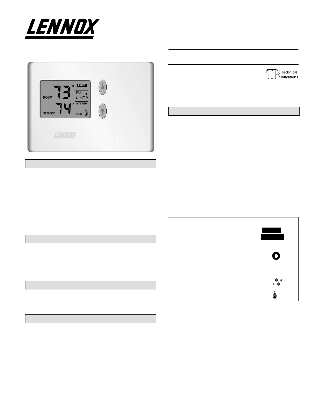
The Lennox Merit® Series Thermostat 51M32 is a nonprogrammable electronic thermostat that is easy-to-use and
has a large, easy-to-read display and excellent temperature control. The thermostat also includes a programmable
filter change reminder and a system check indicator. The
system check indicator will notify the user of the need for
equipment service.
Thermostat 51M32 is suitable for non-heat pump, single−
stage heat/single cool applications that are matched with a
gas or electric furnace.
General
These instructions are intended as a general guide and do
not supersede local codes in any way. Consult authorities
having jurisdiction before installation.
Check equipment for shipping damage. If you find any
damage, immediately contact the last carrier.
Introduction
This document describes the operation of Lennox thermostat
51M32. Refer to the installation manual for instructions regarding installation and wiring of the thermostat.
Initial Thermostat Power-up
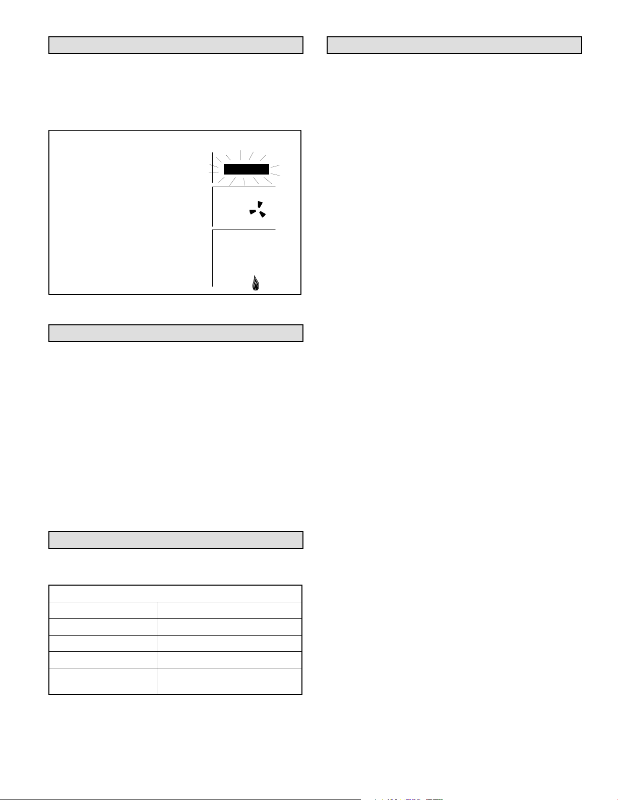
When power is initially applied to the thermostat, the display will appear as shown in figure 1.
MANUAL
Merit® Series Thermostat
CONTROLS (51M32)
504,865M
09/04
RETAIN THESE INSTRUCTIONS
FOR FUTURE REFERENCE
Table of Contents
Merit® Series Thermostat 1. . . . . . . . . . . . . . . . . . . . . .
General 1. . . . . . . . . . . . . . . . . . . . . . . . . . . . . . . . . . . . . . .
Introduction 1. . . . . . . . . . . . . . . . . . . . . . . . . . . . . . . . . . . .
Initial Thermostat Power-up 1. . . . . . . . . . . . . . . . . . . . . .
Heating Control 2. . . . . . . . . . . . . . . . . . . . . . . . . . . . . . . .
Cooling Control 3. . . . . . . . . . . . . . . . . . . . . . . . . . . . . . . .
Adjusting Temperature Setpoint 3. . . . . . . . . . . . . . . . . .
Fan Control 4. . . . . . . . . . . . . . . . . . . . . . . . . . . . . . . . . . . .
Filter Reminder 4. . . . . . . . . . . . . . . . . . . . . . . . . . . . . . . .
Service Indicator 5. . . . . . . . . . . . . . . . . . . . . . . . . . . . . . .
Thermostat Reset 5. . . . . . . . . . . . . . . . . . . . . . . . . . . . . .
Default Thermostat Settings 5. . . . . . . . . . . . . . . . . . . . .
Technical Specifications 5. . . . . . . . . . . . . . . . . . . . . . . . .
Thermostat Output Table 6. . . . . . . . . . . . . . . . . . . . . . . .
Display − Initial Power−Up
ROOM
Litho U.S.A.
FILTER
SERVICE
88
FAN
ON
AUTO
SETPOINT
All display segments are momentarily activated. This occurs as a normal part of thermostat initialization. Within a
few seconds, the display will appear as shown in figure 2
(figure shows temperature in Fahrenheit units).
88
Figure 1
SYSTEM
COOL
OFF
EMG.
HEAT
Page 1
Page 2
Display − Home Screen
Heat Mode Enabled
ROOM
70
FAN
AUTO
SYSTEM
HEAT
Figure 2
Figure 2 illustrates the HOME screen. Note that an indoor
room temperature of 70°F is initially displayed. After about
1 minute of warm−up time, the actual room temperature will
be displayed. HEAT mode is the system default (as indicated in the SYSTEM box at lower right).
A pale blue display backlight will turn on each time a key is
pressed. The backlight will turn off 8 seconds after the last
key is pressed.
Heating Control
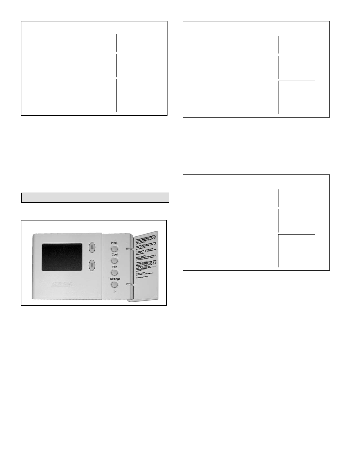
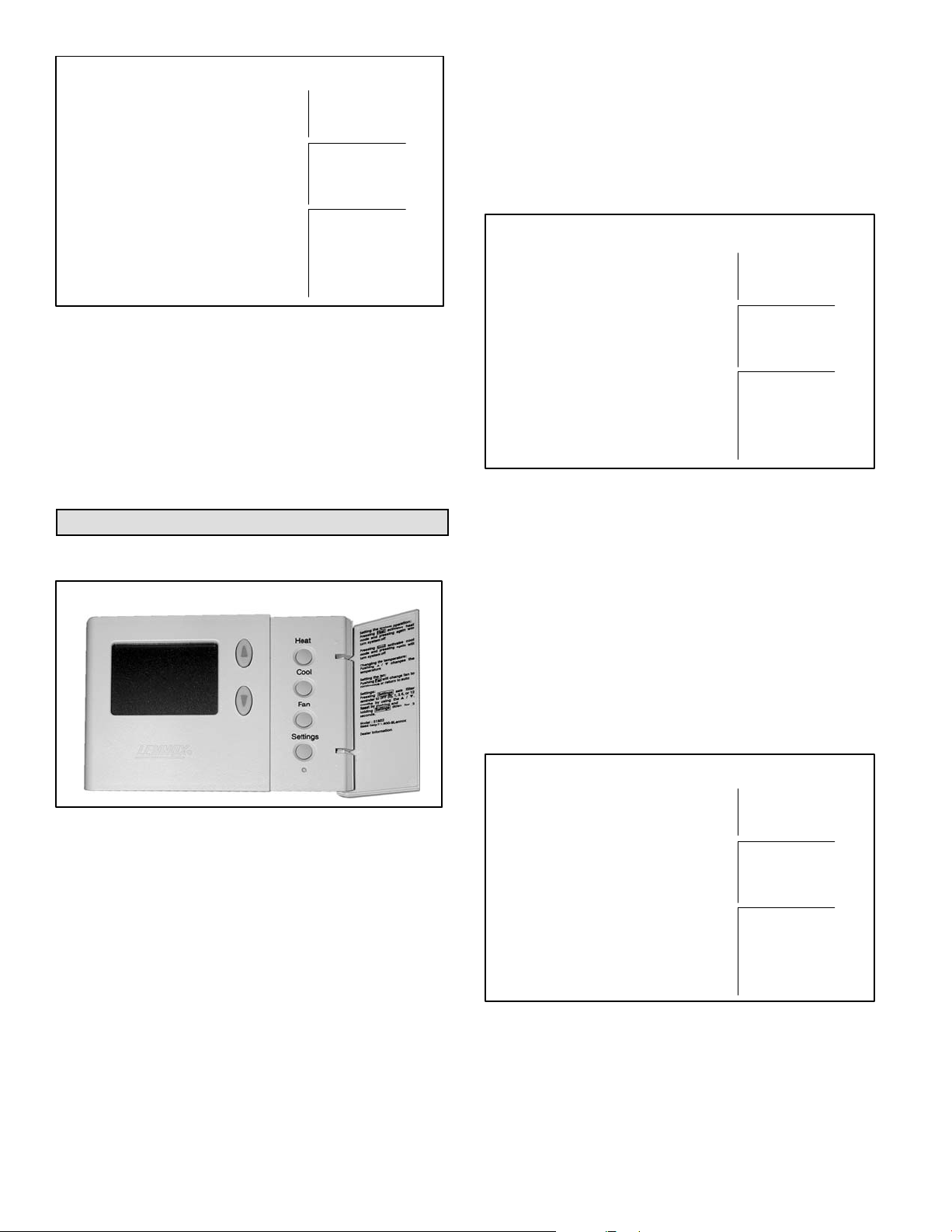
The HEAT button is located behind the small door on the
right−hand side of the thermostat. See figure 3.
ROOM
69
FAN
AUTO
SETPOINT
If the thermostat is in heat mode, heat mode is disabled
when the HEAT button is pressed. This is indicated by OFF
in the SYSTEM box as shown in figure 5.
ROOM
64
Figure 4
Heat Mode Disabled
SYSTEM
HEAT
69
FAN
Additional Thermostat Buttons
Figure 3
Enabling and Disabling Heat Mode
Use the HEAT button to enable or disable heat mode as desired. If the thermostat is in off mode, heat mode is enabled
when the HEAT button is pressed. This is indicated by
HEAT in the SYSTEM box as shown in figure 4.
AUTO
SETPOINT
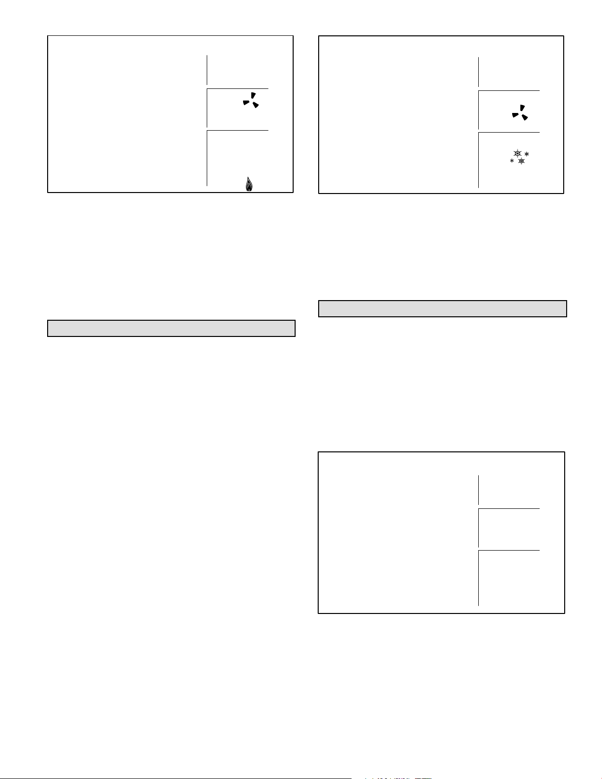
Heating Demand
The thermostat must be in heat mode in order to properly
control the heating equipment. When in heat mode, if the
actual temperature is lower than the temperature setpoint, a
heating demand is detected by the thermostat. The thermostat will then activate the heating equipment to satisfy the demand. Heating operation is indicated by a flame icon in the
SYSTEM box as shown in figure 6.
64
Figure 5
SYSTEM
OFF
Page 2
Page 3
Heating Demand
Cooling Demand
ROOM
72
FAN
AUTO
88
Figure 6
When the actual temperature rises above the temperature
setpoint, the flame icon will disappear. This indicates that
the heating demand has been satisfied and that the heating
equipment has been turned off.
NOTE − The heating equipment is activated for at least 3
minutes if no buttons are pressed during the demand interval.
Cooling Control
The COOL button is located behind the small door on the
right-hand side of the thermostat. See figure 3.
Enabling and Disabling Cool Mode
Use the COOL button to enable or disable cool mode as
necessary. If the thermostat is in off mode, cool mode is enabled when the COOL button is pressed. This is indicated
by COOL in the SYSTEM box.
If the thermostat is in cool mode, cool mode is disabled
when the COOL button is pressed. This is indicated by OFF
in the SYSTEM box.
Cooling Demand
The thermostat must be in cool mode in order to properly
control the cooling equipment. When in cool mode, if the
room temperature is higher than the temperature setpoint,
a cooling demand is detected by the thermostat.
The thermostat will then activate the cooling equipment to
satisfy the demand. Cooling operation is indicated by a
snowflake icon in the SYSTEM box as shown in figure 7.
When the actual temperature drops below the temperature
setpoint, the snowflake icon will disappear. This indicates
that the cooling demand has been satisfied and that the
cooling equipment has been turned off.
SYSTEM
HEAT
ROOM
79
FAN
AUTO
SYSTEM
COOL
Figure 7
NOTE − The cooling equipment is activated for at least 4
minutes if no buttons are pressed during the demand interval. Cooling equipment operation is locked out for 5 minutes after a demand has been satisfied. If another cooling
demand occurs during this 5−minute interval, the snowflake
icon will flash; however, the cooling equipment will not run
until the 5−minute delay has elapsed.
Adjusting Temperature Setpoint
The temperature setpoint represents the desired temperature of the space around the thermostat. The default temperature setpoint is 70°F. To adjust the setpoint, press the
UP or DOWN arrow keys to the right of the display screen.
The existing setpoint will be displayed just below the actual
room temperature as shown in figure 8. Use the UP or
DOWN arrow keys to adjust the setpoint up or down. The
setpoint will increase by 1°F each time the UP key is
pressed. The setpoint will decrease by 1°F each time the
DOWN key is pressed.
Setpoint Display and Adjustment
ROOM
69
FAN
AUTO
SETPOINT
After the desired setpoint is reached, the HOME screen will
reappear after about 8 seconds.
64
Figure 8
SYSTEM
HEAT
Page 3
Page 4
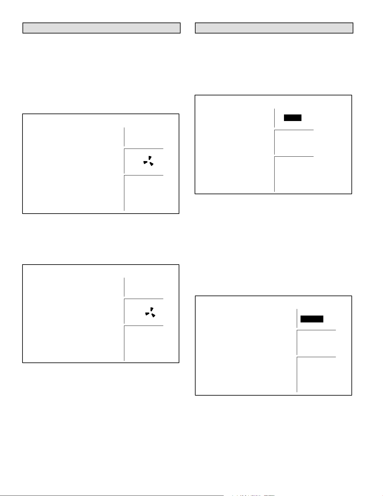
Fan Control
Filter Reminder
The FAN button is located behind the small door on the
right-hand side of the thermostat. See figure 3. The FAN
button can be used to select either continuous fan mode or
auto fan mode.
If continuous fan mode is enabled, the fan will run continuously regardless of whether the heating or cooling equipment is running. Also, ON will be displayed in the FAN box
as shown in figure 9.
Fan ON with Icon
ROOM
73
FAN
ON
SYSTEM
HEAT
Figure 9
If auto fan mode is selected, the fan will only run when the
heating or cooling equipment is running. In this case, AUTO
will be displayed in the FAN box as shown in figure 10.
Fan AUTO with Icon
ROOM
73
FAN
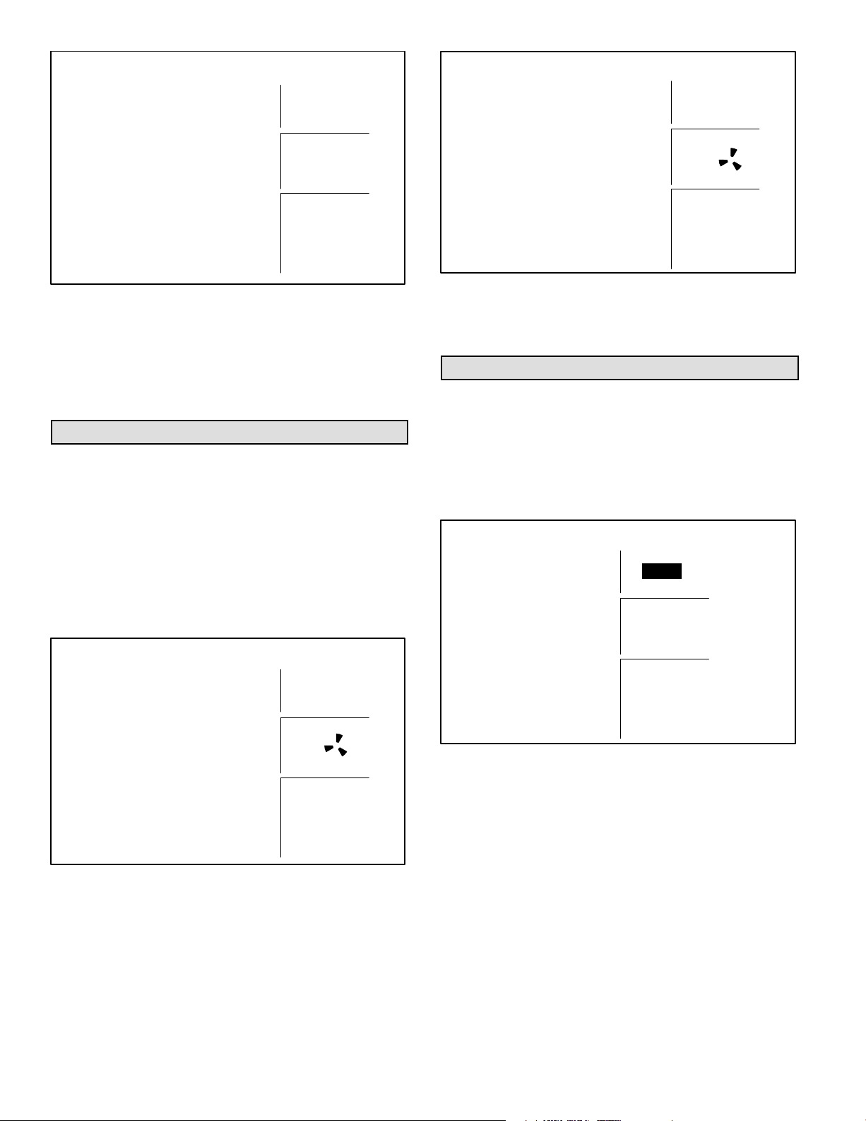
The 51M32 thermostat includes a filter reminder feature.
The filter reminder can be set for 1, 3, 6, or 12−month intervals. The SETTINGS button, located behind the door on
the right−hand side of the thermostat is used to set the filter
reminder interval. See figure 3. Press the SETTINGS button from the HOME screen to display the Filter Reminder
Settings screen as shown in figure 11.
Filter Reminder Settings
Filter
0
Figure 11
The default setting for the filter reminder is 0, which disables the function. Use the UP arrow while in the Filter Reminder Settings screen to select the desired interval between reminders. It may be necessary to press the UP
arrow several times to access the desired setting. The
HOME screen will reappear about 10 seconds after the arrow key has been pressed for the final time.
After the programmed interval has elapsed, the FILTER reminder will be displayed as shown in figure 12. After the filter has been changed, reset the filter reminder by pressing
the SETTINGS button for 4 seconds. The screen will blink
for a few moments to indicate that the timer has been reset.
Display of Filter Reminder
AUTO
SYSTEM
HEAT
Figure 10
To change from continuous to auto fan mode and vice versa,
press the FAN button. Also note the presence of a fan icon in
the FAN box. This icon indicates that the fan is running.
Page 4
ROOM
FILTER
72
FAN
AUTO
SYSTEM
HEAT
Figure 12
Page 5
Service Indicator
Technical Specifications
When abnormal equipment operation is detected, the
SERVICE indicator will flash on the upper-right corner of
the screen. This indicates that the equipment requires service from a qualified service technician. The SERVICE indicator is shown in figure 13.
Service Indicator Flashing
ROOM
SERVICE
73
FAN
AUTO
SYSTEM
HEAT
Figure 13
Thermostat RESET
Under some abnormal conditions, it may be desirable to
reset" the thermostat to its default condition. This can be
useful on rare occasions when the the thermostat is behaving abnormally (e.g. after an electrical storm or power outage). The RESET button can be used to recover from this
situation.
The RESET button is an unlabeled, recessed button located behind the door on the right−hand side of the thermostat, just below the SETTINGS button. The RESET button
is visible in figure 3. Use a paper clip or small pencil to press
the RESET button. After the RESET button is pressed, the
thermostat settings will return to the defaults listed in the
Default Settings section.
Default Thermostat Settings
Default thermostat settings are in table 1.
Table 1
Default Thermostat Settings
Mode Heat
Setpoint 70°F (or 21°C)
Fan Auto
Filter Reminder OFF (reminder setting = 0)
Equipment Protection
Timers
reset back to zero
Thermostat Type
Electronic nonprogrammable thermostat for 1H/1C, gas or
electric heat, non−heat pump, non−power robbing applications.
Power Supply Range
18VAC − 30VAC (24VAC nominal), 60Hz
Temperature Display
Display Scale: Fahrenheit or Celsius user selectable (via
DIP switches)
Display range: 35°F (2°C) to 99°F (37°C)
Display resolution: 1°F (1°C)
Display Accuracy: +/−1°F
Temperature Measurement Range
Measurement Scale: Fahrenheit
Measurement Range: 35°F to 99°F
Measurement Resolution: 0.5°F
Measurement Accuracy: +/−1°F
Field Offset: via DIP switches to +/−3°F
Sampling Method: temperature measurements sampled
every 15 seconds. Displayed temperature is the average of
the last four measurements.
Temperature Setpoint Range
Setting range: 50°F (10°C) to 90°F (32°C)
Setting resolution: 1°F (1°C)
Fan Control
AUTO or ON modes, gas or electric heat compatible via
DIP switches (also see Thermostat Output section).
I/O Relays
All thermostat relays are latching type to minimize power
consumption.
1. HEAT/COOL relay output
2. FAN relay output
3. SERVICE relay input
Equipment Protection Timers
Minimum Compressor OFF time: 5 minutes
Minimum Compressor ON time: 4 minutes
Minimum Furnace ON time: 3 minutes
Minimum furnace cycle time (elapsed time between any
furnace activation and the next furnace activation): 6 minutes.
Minimum elapsed time between any compressor activation
and the next compressor activation: 6 minutes.
NOTE − All protection timers (except the compressor OFF
timer) can be over−ridden if a heating or cooling demand is
initiated or terminated using the UP, DOWN, HEAT, or
COOL buttons.
Page 5
Page 6

Equipment Protection Override
Both the minimum compressor OFF timer and the minimum equipment cycle timer can be over−ridden by pressing and holding either the HEAT or COOL button down for 4
seconds.
Over−Temperature Protection
Thermal mechanical switch opens W1 at 93°F+/−6°F.
Power Loss/Recovery
Thermostat memory is retained for a minimum of 24 hours
during a power loss (includes retention of programmed
temperature setpoint, heat/cool and fan mode settings, filter reminder status, and equipment protection timers). After 24 hours of power loss, programmed settings will be lost
and replaced with default settings.
Filter Reminder
Settings of 0 (Off), 1, 3, 6 or 12 months are available. When
programmed time has elapsed, a FILTER indicator is displayed.
Service Reminder
The SERVICE indicator is displayed only under the following conditions:
if the thermostat Y1 terminal has been activated
with 24VAC for at least 5 minutes, AND the L
terminal is shorted to the R terminal;
OR
if the thermostat Y1 terminal has been activated
with 24VAC for at least 5 minutes, AND the L
terminal is shorted to the C terminal.
Power must be applied for at least six consecutive
hours prior to a power loss in order for memory to be
retained for the specified time.
LCD Backlight
Activated for 8 seconds when any key is pressed.
NOTE − During an electrical storm or similar disturbance,
the backlight may activate for a few seconds. This is normal
and will no longer occur after the electrical disturbance has
passed.
Thermostat Operating Conditions
35°F to 105°F, 5% to 90% RH
Thermostat Storage Conditions
−40°F to 185°F, 5% to 95% RH
IMPORTANT
Thermostat Output Table
The following table depicts the 51M32 thermostat output states for various input conditions. See table 2.
Table 2
Thermostat Outputs
Condition W1 Y1 G
Gas Heat, Auto Fan
heat demand X
cool demand X X
no demand
Gas Heat, Continuous Fan
heat demand X X
cool demand X X
no demand X
Electric Heat, Auto Fan
heat demand X X
cool demand X X
no demand
Electric Heat, Continuous Fan
heat demand X X
cool demand X X
no demand X
NOTE −
X = output is activated with 24VAC.
Page 6
Page 7

®
OPERATION
2003 Lennox Industries Inc.
Dallas, Texas, USA
MeritR Series Thermostat
The Lennox Merit® Series Thermostat 51M33 is a nonprogrammable electronic thermostat that is easy-to-use and
has a large, easy-to-read display and excellent temperature control. The thermostat also includes a programmable
filter change reminder and a system check indicator. The
system check indicator will notify the user of the need for
equipment service.
Thermostat 51M33 is suitable for heat pump, single−stage
heat/single cool applications that are matched with a gas or
electric furnace.
General
These instructions are intended as a general guide and do
not supersede local codes in any way. Consult authorities
having jurisdiction before installation.
Check equipment for shipping damage. If you find any
damage, immediately contact the last carrier.
Introduction
This document describes the operation of Lennox thermostat
51M33. Refer to the installation manual for instructions regarding installation and wiring of the thermostat.
Initial Thermostat Power-up
When power is initially applied to the thermostat, the display will appear as shown in figure 1.
MANUAL
Merit® Series Thermostat
CONTROLS (51M33)
504,931M
09/04
RETAIN THESE INSTRUCTIONS
FOR FUTURE REFERENCE
Table of Contents
Merit® Series Thermostat 1. . . . . . . . . . . . . . . . . . . . . .
General 1. . . . . . . . . . . . . . . . . . . . . . . . . . . . . . . . . . . . . . .
Introduction 1. . . . . . . . . . . . . . . . . . . . . . . . . . . . . . . . . . . .
Initial Thermostat Power-up 1. . . . . . . . . . . . . . . . . . . . . .
Heating Control 2. . . . . . . . . . . . . . . . . . . . . . . . . . . . . . . .
Cooling Control 3. . . . . . . . . . . . . . . . . . . . . . . . . . . . . . . .
Adjusting Temperature Setpoint 3. . . . . . . . . . . . . . . . . .
Fan Control 4. . . . . . . . . . . . . . . . . . . . . . . . . . . . . . . . . . . .
Filter Reminder 4. . . . . . . . . . . . . . . . . . . . . . . . . . . . . . . .
Balance Point 5. . . . . . . . . . . . . . . . . . . . . . . . . . . . . . . . . .
Service Indicator 5. . . . . . . . . . . . . . . . . . . . . . . . . . . . . . .
Thermostat Reset 5. . . . . . . . . . . . . . . . . . . . . . . . . . . . . .
Default Thermostat Settings 6. . . . . . . . . . . . . . . . . . . . .
Technical Specifications 6. . . . . . . . . . . . . . . . . . . . . . . . .
Thermostat Output Table 7. . . . . . . . . . . . . . . . . . . . . . . .
Display − Initial Power−Up
ROOM
Litho U.S.A.
FILTER
SERVICE
88
FAN
ON
AUTO
SETPOINT
All display segments are momentarily activated. This occurs as a normal part of thermostat initialization. Within a
few seconds, the display will appear as shown in figure 2
(figure shows temperature in Fahrenheit units).
88
Figure 1
SYSTEM
COOL
OFF
EMG.
HEAT
Page 1
Page 8
Display − Home Screen
ROOM
70
FAN
AUTO
Enabling and Disabling Heat Mode
Use the HEAT button to select normal heat mode, emergency heat mode, or to disable heat modes as desired. If
the thermostat is in off mode, normal heat mode is enabled
when the HEAT button is pressed. This is indicated by
HEAT in the SYSTEM box as shown in figure 4.
SYSTEM
HEAT
Figure 2
Figure 2 illustrates the HOME screen. Note that an indoor
room temperature of 70°F is initially displayed. After about
1 minute of warm−up time, the actual room temperature will
be displayed. HEAT mode is the system default (as indicated in the SYSTEM box at lower right).
A pale blue display backlight will turn on each time a key is
pressed. The backlight will turn off 8 seconds after the last
key is pressed.
Heating Control
The HEAT button is located behind the small door on the
right−hand side of the thermostat. See figure 3.
Additional Thermostat Buttons
Normal Heat Mode Enabled
ROOM
69
FAN
AUTO
SETPOINT
If the thermostat is in normal heat mode when the HEAT
button is pressed, then emergency heat mode is enabled.
This is indicated by EMG. HEAT in the SYSTEM box as
shown in figure 5.
If the thermostat is in emergency heat mode when the
HEAT button is pressed, then heat modes are disabled.
This is indicated by OFF in the SYSTEM box as shown in
figure 6.
64
Figure 4
SYSTEM
HEAT
Figure 3
Normal Heat Mode
In normal heat mode, both the heat pump and the backup
heat source are used to provide heat. If the thermostat detects that the heat pump is not able to provide enough heat
(as may be the case in very cold weather), then the backup
heat source is activated.
Emergency Heat Mode
In emergency heat mode, only the backup heat source is
used to provide heat. The heat pump is disabled. The backup heat source will be activated only when there is a heat
demand.
Page 2
Emergency Heat Mode Enabled
ROOM
69
FAN
AUTO
SETPOINT
64
Figure 5
SYSTEM
EMG.
HEAT
Page 9

Heat Mode Disabled
ROOM
69
FAN
AUTO
SETPOINT
Heating Demand
The thermostat must be in either normal or emergency
heat mode in order to properly control the heating equipment. When in either heat mode, if the actual temperature is
lower than the temperature setpoint, a heating demand is detected by the thermostat. The thermostat will then activate the
heating equipment to satisfy the demand. Heating operation
is indicated by a flame icon in the SYSTEM box as shown in
figure 7.
ROOM
64
Figure 6
Heating Demand
SYSTEM
OFF
72
FAN
Enabling and Disabling Cool Mode
Use the COOL button to enable or disable cool mode as
necessary. If the thermostat is in off mode, cool mode is enabled when the COOL button is pressed. This is indicated
by COOL in the SYSTEM box.
If the thermostat is in cool mode, cool mode is disabled
when the COOL button is pressed. This is indicated by OFF
in the SYSTEM box.
Cooling Demand
The thermostat must be in cool mode in order to properly
control the cooling equipment. When in cool mode, if the
room temperature is higher than the temperature setpoint,
a cooling demand is detected by the thermostat.
The thermostat will then activate the cooling equipment to
satisfy the demand. Cooling operation is indicated by a
snowflake icon in the SYSTEM box as shown in figure 8.
When the actual temperature drops below the temperature
setpoint, the snowflake icon will disappear. This indicates
that the cooling demand has been satisfied and that the
cooling equipment has been turned off.
Cooling Demand
ROOM
79
FAN
AUTO
AUTO
88
Figure 7
When the actual temperature rises above the temperature
setpoint, the flame icon will disappear. This indicates that
the heating demand has been satisfied and that the heating
equipment has been turned off.
NOTE − The heat pump is activated for at least 4 minutes if
no buttons are pressed during the demand interval. The
backup heat source is activated for at least 3 minutes if no
buttons are pressed during the demand interval.
Heat pump operation is locked out for 5 minutes after a demand has been satisfied. If another heat pump demand occurs during this 5−minute interval, the flame icon will flash;
however, the heat pump will not run until the 5−minute delay
has elapsed.
SYSTEM
HEAT
Cooling Control
The COOL button is located behind the small door on the
right-hand side of the thermostat. See figure 3.
SYSTEM
COOL
Figure 8
NOTE − The cooling equipment is activated for at least 4
minutes if no buttons are pressed during the demand interval. Cooling equipment operation is locked out for 5 minutes after a demand has been satisfied. If another cooling
demand occurs during this 5−minute interval, the snowflake
icon will flash; however, the cooling equipment will not run
until the 5−minute delay has elapsed.
Adjusting Temperature Setpoint
The temperature setpoint represents the desired temperature of the space around the thermostat. The default temperature setpoint is 70°F. To adjust the setpoint, press the
UP or DOWN arrow keys to the right of the display screen.
The existing setpoint will be displayed just below the actual
room temperature as shown in figure 9. Use the UP or
DOWN arrow keys to adjust the setpoint up or down. The
setpoint will increase by 1°F each time the UP key is
pressed. The setpoint will decrease by 1°F each time the
DOWN key is pressed.
Page 3
Page 10
Setpoint Display and Adjustment
Fan AUTO with Icon
ROOM
69
FAN
AUTO
SETPOINT
After the desired setpoint is reached, the HOME screen will
reappear after about 8 seconds.
Fan Control
The FAN button is located behind the small door on the
right-hand side of the thermostat. See figure 3. The FAN
button can be used to select either continuous fan mode or
auto fan mode.
If continuous fan mode is enabled, the fan will run continuously regardless of whether the heating or cooling equipment is running. Also, ON will be displayed in the FAN box
as shown in figure 10.
64
Figure 9
SYSTEM
HEAT
ROOM
73
FAN
AUTO
SYSTEM
HEAT
Figure 11
To change from continuous to auto fan mode and vice versa,
press the FAN button. Also note the presence of a fan icon in
the FAN box. This icon indicates that the fan is running.
Filter Reminder
The 51M33 thermostat includes a filter reminder feature.
The filter reminder can be set for 1, 3, 6, or 12−month intervals. The SETTINGS button, located behind the door on
the right−hand side of the thermostat is used to set the filter
reminder interval. See figure 3. Press the SETTINGS button from the HOME screen to display the Filter Reminder
Settings screen as shown in figure 12.
Filter Reminder Settings
Filter
0
Fan ON with Icon
ROOM
73
FAN
ON
SYSTEM
HEAT
Figure 10
If auto fan mode is selected, the fan will only run when the
heating or cooling equipment is running. In this case, AUTO
will be displayed in the FAN box as shown in figure 11.
Figure 12
The default setting for the filter reminder is 0, which disables the function. Use the UP arrow while in the Filter Reminder Settings screen to select the desired interval between reminders. It may be necessary to press the UP
arrow several times to access the desired setting. The
HOME screen will reappear about 10 seconds after the arrow key has been pressed for the final time.
After the programmed interval has elapsed, the FILTER reminder will be displayed as shown in figure 13. After the filter has been changed, reset the filter reminder by pressing
the SETTINGS button for 4 seconds. The screen will blink
for a few moments to indicate that the timer has been reset.
Page 4
Page 11

Display of Filter Reminder
ROOM
72
Figure 13
FILTER
FAN
AUTO
SYSTEM
HEAT
DOWN arrow keys to the right of the display screen. The
balance point setting will increase by 1°F each time the UP
key is pressed. The balance point setting will decrease by
1°F each time the DOWN key is pressed.
After the desired balance point is reached, the HOME
screen will reappear after about eight seconds.
NOTE − The balance point feature allows the temperature
to rise or fall 3°F above or below the setpoint. This prevents
excessive cycling of the equipment when the outdoor temperature is near the balance point. For example, if the balance point is 40°F and the actual outdoor temperature is
35°F, the outdoor temperature must rise to 43°F before
equipment adjustment occurs. Conversely, if the balance
point is 40°F and the actual outdoor temperature is 45°F,
the outdoor temperature must drop to 37°F before equipment adjustment occurs.
Balance Point
NOTE − The balance point is only available with the outdoor sensor.
If the optional outdoor sensor (X2658) is connected to the
thermostat, balance point adjustment is available. The balance point feature allows the measured outdoor temperature to govern operation of the heat pump and backup heat
source.
Use the SETTINGS button to access the balance point setting. If the outdoor sensor is attached to the thermostat,
press the SETTINGS button twice to access the Balance
Point Settings screen (see figure 14).
Balance Point Setting
6P
SETPOINT
The balance point can be set at any temperature between
1°F and 55°F (−17°C to 13°C). A balance point setting of
zero disables the balance point function (in this case, the
thermostat behaves as if no outdoor sensor is attached).
The default balance point setting is 55°F.
To adjust the balance point up or down, press the UP or
55
Figure 14
Service Indicator
When abnormal equipment operation is detected, the
SERVICE indicator will flash on the upper-right corner of
the screen. This indicates that the equipment requires service from a qualified service technician. The SERVICE indicator is shown in figure 15.
Service Indicator Flashing
ROOM
SERVICE
73
FAN
AUTO
SYSTEM
HEAT
Figure 15
Thermostat RESET
Under some abnormal conditions, it may be desirable to reset the thermostat to its default condition. The RESET button can be used to return the unit to normal operation after
an occurrence such as an electrical storm or power outage.
The RESET button is an unlabeled, recessed button located behind the door on the right−hand side of the thermostat, just below the SETTINGS button. The RESET button
is visible in figure 3. Use a paper clip or small pencil to press
the RESET button. After the RESET button is pressed, the
thermostat settings will return to the defaults listed in the
Default Settings section.
Page 5
Page 12

Default Thermostat Settings
Default Thermostat settings are in table 1.
Table 1
Default Thermostat Settings
Mode Heat
Setpoint 70°F (or 21°C)
Fan Auto
Filter Reminder OFF (reminder setting = 0)
Equipment Protection
Timers
reset back to zero
Technical Specifications
Thermostat Type
Electronic nonprogrammable thermostat for 1H/1C, heat
pump with electric or gas backup heat source, non−power
robbing applications.
Power Supply Range
18VAC − 30VAC (24VAC nominal), 60Hz
Temperature Display
Display Scale: Fahrenheit or Celsius user selectable (via
DIP switches)
Display range: 35°F (2°C) to 99°F (37°C)
Display resolution: 1°F (1°C)
Display Accuracy: +/−1°F
Temperature Measurement Range
Measurement Scale: Fahrenheit
Measurement Range: 35°F to 99°F
Measurement Resolution: 0.5°F
Measurement Accuracy: +/−1°F
Field Offset: via DIP switches to +/−3°F
Sampling Method: temperature measurements sampled
every 15 seconds. Displayed temperature is the average of
the last four measurements.
Temperature Setpoint Range
Setting range: 50°F (10°C) to 90°F (32°C)
Setting resolution: 1°F (1°C)
Fan Control
AUTO or ON modes.
Backup Heat Source Selection
Electric or gas furnace, selectable via DIP switch #5 (Aux or
Dual, respectively). See also Thermostat Output section.
I/O Relays
All thermostat relays are latching type to minimize power
consumption. See table 2.
Table 2
51M33 Terminal Designations
Connections Description
O Reversing valve, cool active
B Reversing valve, heat active
R 24VAC
G Fan control
Y1 First stage cooling/heating, compres-
sor generated
W1 Auxiliary heating, furnace generated
L Service Indicator
C 24VAC common
E Emergency heat
T Outdoor temperature sensor
connection 1
T Outdoor temperature sensor
connection 2
Equipment Protection Timers
Minimum Compressor OFF time: 5 minutes
Minimum Compressor ON time: 4 minutes
Minimum Furnace ON time: 3 minutes
Minimum backup furnace cycle time (elapsed time between any furnace activation and the next furnace activation): 6 minutes.
Minimum elapsed time between any compressor activation
and the next compressor activation: 6 minutes.
NOTE − All protection timers (except the compressor OFF
timer) can be over−ridden if a heating or cooling demand is
initiated or terminated using the UP, DOWN, HEAT, or
COOL buttons.
Equipment Protection Override
Both the minimum compressor OFF timer and the minimum equipment cycle timer can be over−ridden by pressing and holding either the HEAT or COOL button down for 4
seconds.
Over−Temperature Protection
Thermal mechanical switch opens W1 at 93°F+/−6°F.
Filter Reminder
Settings of 0 (Off), 1, 3, 6 or 12 months are available. When
programmed time has elapsed, a FILTER indicator is displayed.
Balance Point
0°F (OFF) to 55°F, user selectable.
Page 6
Page 13

Service Reminder
The SERVICE indicator is displayed only under the following conditions:
if the thermostat Y1 terminal has been activated
with 24VAC for at least 5 minutes, AND the L
terminal is shorted to the R terminal;
OR
if the thermostat Y1 terminal has been activated
with 24VAC for at least 5 minutes, AND the L
terminal is shorted to the C terminal.
Power Loss/Recovery
Thermostat memory is retained for a minimum of 24 hours
during a power loss (includes retention of programmed
temperature setpoint, heat/cool and fan mode settings, filter reminder status, and equipment protection timers). After 24 hours of power loss, programmed settings will be lost
and replaced with default settings.
IMPORTANT
Power must be applied for at least six consecutive
hours prior to a power loss in order for memory to be
retained for the specified time.
LCD Backlight
Activated for 8 seconds when any key is pressed.
NOTE − During an electrical storm or similar disturbance,
the backlight may activate for a few seconds. This is normal
and will no longer occur after the electrical disturbance has
passed.
Thermostat Operating Conditions
35°F to 105°F, 5% to 90% RH
Thermostat Storage Conditions
−40°F to 185°F, 5% to 95% RH
Thermostat Output Table
Table 3 (see page 8) provides details of the 51M33 thermostat output states for various input conditions.
Page 7
Page 14

Table 3
Thermostat Output States
Condition W1 Y1 G O E
Electric Heat Backup − No Outdoor Sensor
small heat demand X X
large heat demand X X X
emergency heat demand X X
cool demand X X X
no demand dc
Gas Heat Backup (Dual Fuel) − No Outdoor Sensor
small heat demand X X
large heat demand X
emergency heat demand X
cool demand X X X
no demand dc
Electric Heat Backup − Outdoor Sensor Attached
small heat demand (BBP) X X
large heat demand (BBP) X X X
small heat demand (ABP) X X
large heat demand (ABP) X X
emergency heat demand X X
cool demand X X X
no demand dc
Gas Heat Backup (Dual Fuel) − Outdoor Sensor Attached
small heat demand (BBP) X
large heat demand (BBP) X
small heat demand (ABP) X X
large heat demand (ABP) X
emergency heat demand X
cool demand X X X
no demand dc
NOTE −
X = output is activated with 24VAC
dc: does not care (output can be in either state, i.e., either active or inactive)
BBP: outdoor temperature is below balance point
ABP: outdoor temperature is above balance point
small heat demand: temperature is between (setpoint − 1.5°F) and (setpoint − 0.5°F), and 30-minute upstage
timer has not expired (see Normal Heat Mode graph)
large heat demand: temperature is below (setpoint − 1.5°F), or 30-minute upstage timer has expired (see Nor-
mal Heat Mode graph)
the state of the B terminal is opposite the state of the O terminal.
data above are tabulated for AUTO fan setting. If fan setting is ON, the fan is activated in all cases.
Page 8
 Loading...