

Page 1

INSTALLAT I STRUCTIO
Gas
(2,4)PG E/SG(13/15)
Heatin ectric Coolin
SAFETY ................................................. 2
INSTALLATION ....................................... 2
START-UP ............................................ 10
OPERATION ........................................ 11
MAINTENANCE ................................... 13
Series
Package Unit
TABLE OF CONTENTS
CONTROL SYSTEM DIAGNOSTICS .. 14
WIRING DIAGRAMS ............................ 15
Manufactured By
A.A.C.
A Lennox International Inc. Company
421 Monroe Street
Bellevue, OH 44811
6AS-HREB
II!il!iilIIIllUI!11II o
I A CAUTION1
The installation of the furnace, wiring, warm air ducts, venting, etc. must conform to the requirements of the
National Fire Protection Association; the National Fuel Gas Code, ANSI Z223.1 (latest edition) and the
National Electrical Code, ANSl/NFPA No. 70 (latest edition) in the United States; the Canadian Installation
Codes CAN/CGA-B149.1 & .2 (latest edition) and the Canadian Electrical Code Part 1, CSA 22.1 (latest
edition) in Canada; and any state or provincial laws, local ordinances, or local gas utility requirements. Local
authorities having jurisdiction should be consulted before installation is made. Such applicable regulations
or requirements take precedence over the general instructions in this manual.
# 48111B005 Save these instructionsfor future reference Page 1
Page 2
SAFETY INSTALLATION
The following is a list of safety rules and precautions that
must be followed when installing this furnace.
1. Use only with the type of gas approved for this
furnace. Refer to the furnace rating plate.
2. Install this furnace only in a location and position as
specified in the Location section on page 3 of these
instructions.
3. Adequate clearance must be provided around the vent
hood as specified in the Clearances section on page 4
of these instructions.
4.
Never test for gas leaks with an open flame. Use a
commercially available soap solution made specifi-
cally for the detection of leaks to check all connec-
tions, as specified in Gas Supply and Piping
beginning on page 6 of these instructions.
Always install furnace to operate within the furnace's
intended temperature-rise range with a duct system
which has an external static pressure within the allowable
range, as specified in Temperature Rise on page 11 of
these instructions. See furnace rating plate.
These instructions must be hung on or near the
furnace in a conspicuous place.
These units are single package air conditioners with gas
heat designed for outdoor installation on a rooftop or a slab.
The units are completely assembled. All piping, refrigerant
charge, and electrical wiring are factory installed and
tested. The units require only electric power, gas piping,
condensate drain, and duct connections, plus assembly of
the heating vent hood at the point of installation.
If components are to be added to a unit to meet local
codes, they are to be installed at the dealer's and/or
customer's expense.
The size of unit for the proposed installation should be based
on heat loss/heat gain calculation made according to the
methods of Air Conditioning Contractors of America (ACCA).
These installation instructions are intended as a
general guide only, for use by an experienced, quali-
fied contractor.
These units are listed by UL:
6.
The furnace is not recommended for use for temporary
heating of buildings or structures under construction
unless certain installationand operating conditions are
adhered to, as specified in the Location section on
page 3 of these instructions.
• For use as a forced air furnace with cooling unit.
For outdoor installation only.
For installation on combustible material.
For use with natural gas or propane gas.
(Conversion kit required for propane gas application.)
These units are not suitable for use with conventional
venting systems.
IMPORTANT: This product has been designed and manu-
factured to meet ENERGY STAR criteria for energy effi-
ciency. However, proper refrigerant charge and proper air
flow are critical to achieve rated capacity and efficiency.
Installation of this product should follow the manufacturer's
refrigerant charging and airflow instructions. Failure to
confirm proper charge and airflow may reduce energy
efficiency and shorten equipment life.
inspection
As soon as the unit is received, it should be inspected for
possible damage during transit. Ifdamage is evident, the
extent of the damage should be noted on the carrier's
freight bill. A separate request for inspection by the
carrier's agent should be made in writing.
Page 2 # 48111 B005
Page 3
Location • Air filters must be replaced upon construction completion.
Use the following guidelines to select a suitable location
for the unit.
1. Unit is designed for outdoor installation only. Unit must
be installed so all electrical components are protected
from water.
2. Condenser coils must have an unlimited supply of air.
3. For ground level installation, use a level prefabricated
pad or use a level concrete slab. Do not tie the slab to
the building foundation.
4. Maintain level within a tolerance of 1/4" maximum
across the entire length or width of the unit.
5. Do not locate the unit where the combustion air supply
will be exposed to any of the following substances:
Permanent wave solutions
Chlorinated waxes and cleaners
Chlorine-based swimming pool chemicals
Water softening chemicals
Deicing salts or chemicals
Carbon tetrachloride
Halogen-type refrigerants
Cleaning solvents (such as perchloroethylene)
Printing inks, paint removers, varnishes, etc.
Cements and glues
Antistatic fabric softeners for clothes dryers
Masonry acid washing materials
Chlorinated laundry products
Hydrochloric acid
The input rate and temperature rise must be set per
the unit rating plate.
100% outdoor air must be provided for combustion air
requirements during construction, installation of this unit
in its intended outdoor location will accomplish this.
The heat exchanger, components, duct system, air
filter(s), and evaporator coil must be thoroughly
cleaned following final construction cleanup.
Following the final cleaning, all furnace operating
conditions (including ignition, input rate, temperature
rise, and venting) must be verified according to these
instructions.
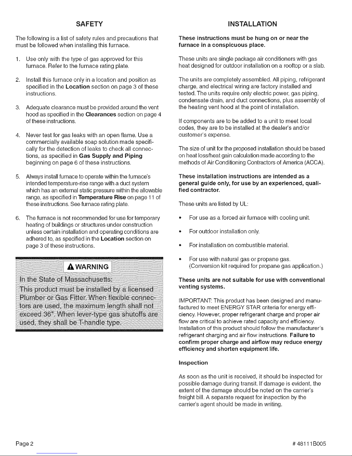
Exercise care when moving the unit. Do not remove any
packaging until the unit is near the place of installation. An
accessory lift kit can be purchased to aid in rigging (see
Figure 1). Spreaders whose length exceed the largest
dimension across the unit must be used across the top
of the unit. Recommended spreader length: 3 ton and
smaller package units- 44", 3.5 ton and larger units - 54".
Units may also be moved or lifted with a forklift while still in
the factory-supplied packaging. The lengths of the forks
of the forklift must be a minimum of 42".
Use of unit as a construction heater during any phase of
construction is not recommended. Very low return air
temperatures, harmful vapors, and operation of the unit
with clogged or misplaced filters will damage the unit.
However, if the installation and operating conditions
specified below are followed, use of this unit for heating of
buildings or structures under construction is permissible:
The vent hood must be installed per these installation
instructions.
A room thermostat must control the furnace. The use
of fixed jumpers that will provide continuous heating is
not allowed.
The return air duct must be provided and sealed to
the unit.
Return air temperature must be maintained between
60°F (16°0) and 80°F (27°0).
Air filters must be installed in the system and must be
maintained during construction.
# 48111 BOO5 Page 3
Using Accessory Lift Kit
Spreaders
(Field Supplied)
To avoid possible
damage to unit
panels from lifting
clevis, place
packing material
between clevis
and panels before
lifting unit.
Figure 1
Page 4
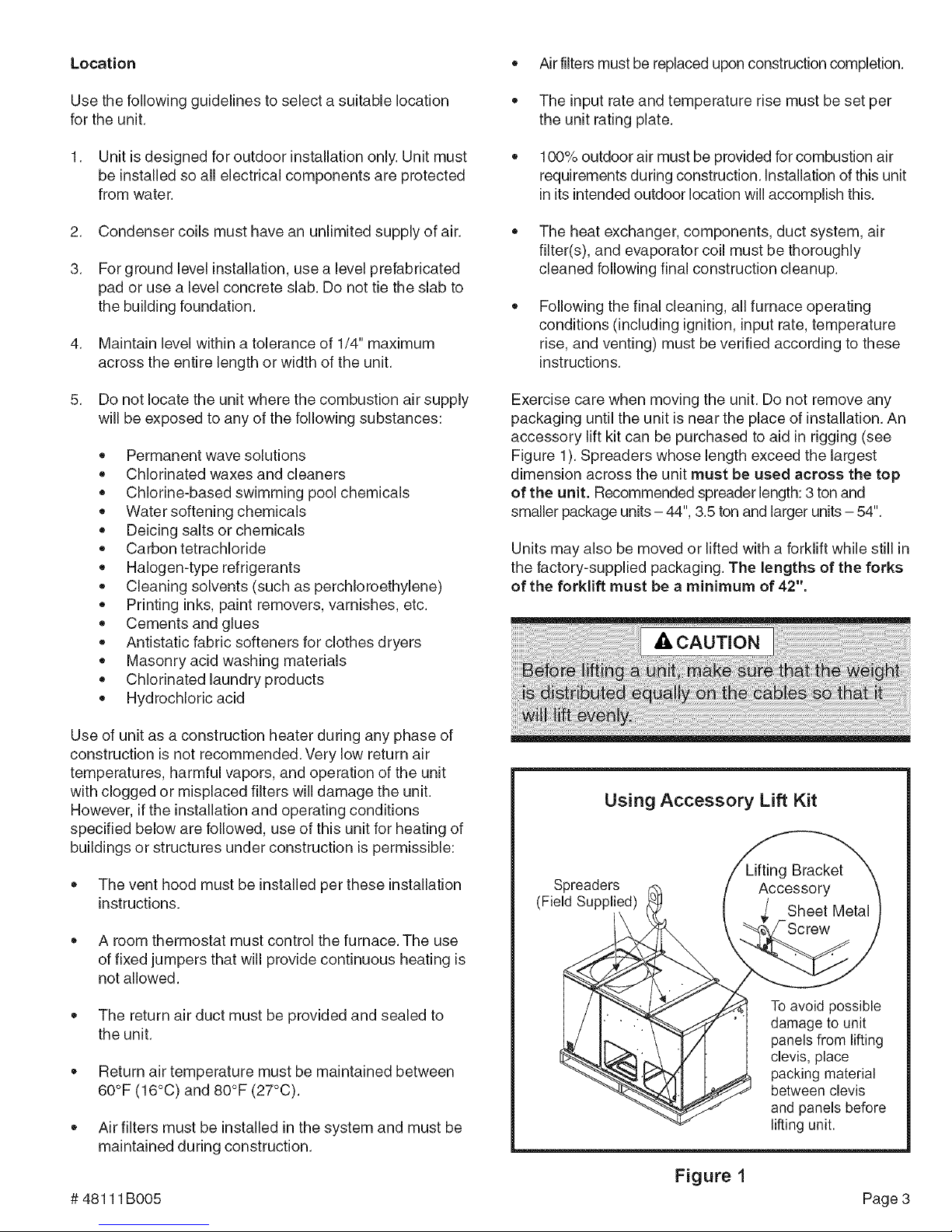
Roof Curb Installation
If a roof curb is used, follow the manufacturer's installation
instructions and be sure that all required clearances are
observed (see following Clearances section).
Roof Curb Assembly
Figure 2
Clearances
All units require certain clearances for proper operation
and service. Refer to Table 1 for the minimum clearances
to combustibles as well as minimum clearances neces-
sary for servicing and proper unit operation.
Minimum Clearance Requirements
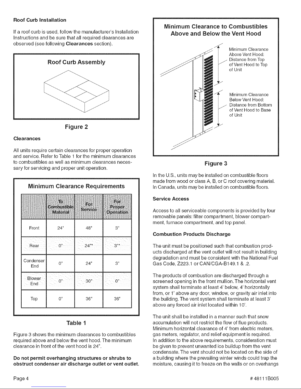
Minimum Clearance to Combustibles
Above and Below the Vent Hood
Minimum Clearance
Above Vent Hood:
Distance from Top
of Vent Hood to Top
of Unit
Minimum Clearance
Below Vent Hood:
Distance from Bottom
of Vent Hood to Base
of Unit
Figure 3
In the U.S., units may be installed on combustible floors
made from wood or class A, B, or C roof covering material.
In Canada, units may be installed on combustible floors.
Front 24" 48" 3"
Rear 0!! 24!!* 3!!_
Condenser
End
Blower , '
End . . ,
Top 0" 36" 36"
0" 24" 3"
0!' 30" 0!!
n n
Table 1
Figure 3 shows the minimum clearances to combustibles
required above and below the vent hood. The minimum
clearance in front of the vent hood is 24".
Do not permit overhanging structures or shrubs to
obstruct condenser air discharge outlet or vent outlet.
Service Access
Access to all serviceable components is provided by four
removable panels: filter compartment, blower compart-
ment, furnace compartment, and top panel.
Combustion Products Discharge
The unit must be positioned such that combustion prod-
ucts discharged at the vent outlet will not result in building
degradation and must be consistent with the National Fuel
Gas Code, Z223.1 or CAN/CGA-B149.1 & .2.
The products of combustion are discharged through a
screened opening in the front mullion. The horizontal vent
system shall terminate at least 4' below, 4' horizontally
from, or 1' above any door, window, or gravity air inlet into
the building. The vent system shall terminate at least 3'
above any forced air inlet located within 10'.
The unit shall be installed in a manner such that snow
accumulation will not restrict the flow of flue products.
Minimum horizontal clearance of 4' from electric meters,
gas meters, regulator, and relief equipment is required.
In addition to the above requirements, consideration must
be given to prevent unwanted ice buildup from the vent
condensate. The vent should not be located on the side of
a building where the prevailing winter winds could trap the
moisture, causing it to freeze on the walls or on overhangs
Page 4 # 48111 B005
Page 5
(undereaves).Theventlocationshouldnotdischarge
overasidewalk,patio,orotherwalkwaywherethecon-
densatecouldcausethesurfacetobecomeslippery.
kWARNING
The products of combustion must not be allowed to
accumulate within a confined space and recirculate.
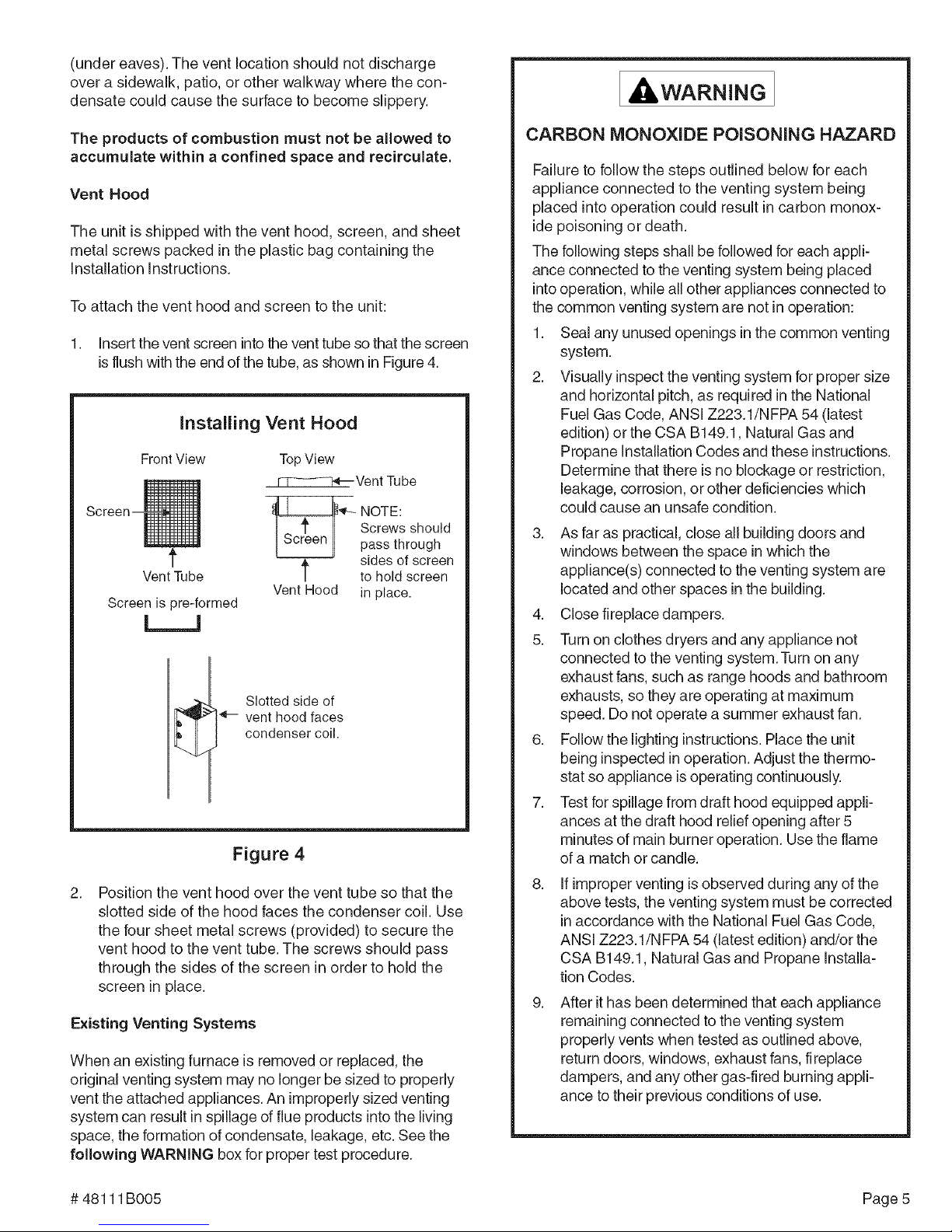
Vent Hood
The unit is shipped with the vent hood, screen, and sheet
metal screws packed in the plastic bag containing the
Installation Instructions.
To attach the vent hood and screen to the unit:
1. Insert the vent screen into the vent tube so that the screen
is flush with the end of the tube, as shown in Figure 4.
Installing Vent Hood
FrontView TopView
_Vent Tube
'_-- OTE:
Screws should
pass through
sides of screen
VentTube
Screen is lore-formed
t to hold screen
Vent Hood in place.
L__J
_-- vent hood faces
condenser coil.
Slotted side of
Figure 4
2. Position the vent hood over the vent tube so that the
slotted side of the hood faces the condenser coil. Use
the four sheet metal screws (provided) to secure the
vent hood to the vent tube. The screws should pass
through the sides of the screen in order to hold the
screen in place.
Existing Venting Systems
When an existing furnace is removed or replaced, the
original venting system may no longer be sized to properly
vent the attached appliances. An improperly sized venting
system can result in spillage of flue products into the living
space, the formation of condensate, leakage, etc. See the
following WARNING box for proper test procedure.
CARBON MONOXIDE POISONING HAZARD
Failure to follow the steps outlined below for each
appliance connected to the venting system being
placed into operation could result in carbon monox-
ide poisoning or death.
The following steps shall be followed for each appli-
ance connected to the venting system being placed
into operation, while all other appliances connected to
the common venting system are not in operation:
1. Seal any unused openings in the common venting
system.
2. Visually inspect the venting system for proper size
and horizontal pitch, as required in the National
Fuel Gas Code, ANSI Z223.1/NFPA 54 (latest
edition) orthe CSA B149.1, Natural Gas and
Propane Installation Codes and these instructions.
Determine that there is no blockage or restriction,
leakage, corrosion, or other deficiencies which
could cause an unsafe condition.
3. As far as practical, close all building doors and
windows between the space in which the
appliance(s) connected to the venting system are
located and other spaces inthe building.
4. Close fireplace dampers.
5. Turn on clothes dryers and any appliance not
connected to the venting system. Turn on any
exhaust fans, such as range hoods and bathroom
exhausts, so they are operating at maximum
speed. Do not operate a summer exhaust fan.
6. Follow the lighting instructions. Place the unit
being inspected in operation. Adjust the thermo-
stat so appliance is operating continuously.
7. Test for spillage from draft hood equipped appli-
ances at the draft hood relief opening after 5
minutes of main burner operation. Use the flame
of a match or candle.
8.
If improper venting is observed during any of the
above tests, the venting system must be corrected
in accordance with the National Fuel Gas Code,
ANSI Z223.1/N FPA 54 (latest edition) and/or the
CSA B149.1, Natural Gas and Propane installa-
tion Codes.
9.
After it has been determined that each appliance
remaining connected to the venting system
properly vents when tested as outlined above,
return doors, windows, exhaust fans, fireplace
dampers, and any other gas-fired burning appli-
ance to their previous conditions of use.
# 48111B005 Page 5
Page 6

CondensateDrain
1. Remove screw on cover nearest side opening.
ThePGE/SGpackageunitisequippedwitha3/4"FPT
couplingforcondensatelineconnection.Plumbingmust
conformtolocalcodes.Useasealingcompoundonmale
pipethreads.
The condensate drain line must be properly trapped
and routed to a suitable drain. See Figure 5 for proper
drain arrangement. The drain line must pitch to an open
drain or pump to prevent clogging of the line. Seal around
the drain connection with suitable material to prevent air
leakage into the return air system.
Typical Condensate Drain Connection
Unit /_ Drain Connection
1.00" Min.
,, 3oo:,
2. Lift end of cover slightly and push to slide back screw/
pin free from duct flange.
3. Slide duct cover out the side duct opening.
Removing Bottom Duct Covers
®
(b
1. Remove screw and lift.
2. Slide cover to free back pin.
Figure 6
Base_ J
' Max. '_
Positive Liquid Seal Required _
Figure 5
Ductwork
Ductwork should be designed and sized according to the
methods in Manual Q of the Air Conditioning Contractors
of America (ACCA).
A closed return duct system shall be used. This shall not
preclude use of economizers or outdoor fresh air intake. It
is recommended that supply and return duct connections
at the unit be made with flexible joints.
The supply and return air duct systems should be de-
signed for the CFM and static requirements of the job.
They should not be sized by matching the dimensions
of the duct connections on the unit.
Outdoor ductwork must be insulated and waterproofed.
Equipment is shipped for side ductwork connection. The
unit can be converted to bottom ductwork connection by
removing the duct covers located over the bottom duct
openings and placing these covers over the side duct
openings (see Figure 6).
To remove the bottom duct cover over supply opening:
Filters
Air filters are to be used with this heating/cooling unit.
Filters are not factory supplied in the unit. However, a filter
frame accessory isavailable from the manufacturer that
allows filters to be installed within the unit. if the filter
frame accessory isnot used, a filter must be installed in
the duct work by the installer. Filters must always be
installed ahead of the evaporator coil and must be kept
clean or replaced. Dirty filters will reduce the airflow of the
unit. Filters should be sized in accordance with Table 2.
Gas Supply and Piping
Refer to the furnace rating plate to make sure the furnace
isequipped to burn the gas supplied (natural or propane).
See LPG/Propane Units, Tanks, and Piping on page 7
for more information on converting to propane gas.
Gas supply piping should be installed in accordance with
local codes and the regulations of the utility. In the ab-
sence of local codes, the latest edition of the National Fuel
Gas Code ANSI Z223.1 (in the U.S.), orthe Natural Gas
and Propane installation Codes CAN/CGA B149.1 &
Page 6 # 48111 B005
Page 7

Minimum Required Surface Area
for Disposable Filters
24,000 2.67
30,000 I 3.33
36,000
|
4.00
codes. An 1/8" NPT plugged tapping, accessible for test
gauge connection, must be installed immediately up-
stream of the gas supply connection to the unit. A sedi-
ment trap (drip leg) shall be installed as close as practical
to the gas supply inlet of the unit.
The furnace must be isolated from the gas supply piping
system by closing the individual manual shutoff valve
during any pressure testing of the gas supply piping
system at test pressure equal to or less than 1/2 psig
(3.5 kPa) or 14" W.C. If the piping system is to be tested at
pressures in excess of 1/2 psig (3.5 kPa), the furnace and
its appliance main gas valve must be disconnected from
the gas supply piping system.
48,000
I
5.33
60,000 _ 6.67
Table 2
B149.2 (in Canada), should be followed. Piping must be of
adequate size to prevent undue pressure drop. Consult
the local utility or gas supplier for complete details on
special requirements for sizing gas piping.
The gas supply line should be routed through the grom-
met on the side of the unit. Refer to Figure 7 to locate this
access opening.
Gas and Electrical Access
Gas Line
After gas piping is complete, carefully check all piping
connections (factory and field) for gas leaks. Use a leak
detecting solution or other preferred means. Some soaps
used for leak detection are corrosive to certain metals.
Carefully rinse piping thoroughly after leak detection has
been completed.
Thermostat _C)
Entry
Line Voltage
Entry
Figure 7
If local codes allow the use of a flexible gas appliance
connector, always use a new listed connector. Do not use
a connector which has previously serviced another gas
appliance.
Pipe connections must be tight, and a non-hardening pipe
compound resistant to liquefied petroleum gases should
be used.
Install a manual shutoff valve in the gas connection to the
unit, external to the casing, in accordance with local
# 48111B005 Page 7
LPG/Propane Units, Tanks, and Piping
Units are shipped equipped for natural gas, but can be
converted to LPG/propane in the field by an approved
licensed technician.
All LPG/propane gas equipment must conform to the safety
standards of the National Fire Protection Association.
Page 8

Forsatisfactoryoperation,LPG/propanegaspressure
mustbeaminimumof11"W.C.attheunitunderfullload.
Completeinformationregardingtanksizingforvaporiza-
tion,recommendedregulatorsettings,andpipesizingis
availablefrommostregulatormanufacturersandLPG/
propanegassuppliers.
Checkallconnectionsforleakswhenpipingiscompleted,
usingasoapysolution.Somesoapsusedforleakdetec-
tionare corrosive to certain metals. Carefully rinse
piping thoroughly after completing leak detection.
Thermostat
The room thermostat should be located on an inside wall
where it will not be subject to drafts, sun exposure, or heat
from electrical fixtures or appliances. Follow the
manufacturer's instructions enclosed with thermostat for
general installation procedure. Color-coded insulated wires
(#18 AWG) should be used to connect thermostat to unit.
Four wires are required for cooling. The heat anticipator
setting is 0.7 amp.
Compressor
Units are shipped with compressor mountings factory-
adjusted and ready for operation. Caution: Do not
loosen compressor mounting bolts.
Electrical Wiring
All wiring should be done in accordance with the
National Electrical Code, ANSI/NFPA No. 70 (latest
edition); Canadian Electrical Code Part 1, CSA C22.1
(latest edition); or local codes where they prevail. Use
wiring with a temperature limitation of 75°C minimum. Run
the 208 or 230 volt, 60 hertz electric power supply through
a fused disconnect switch to the connection box of the unit
and connect as shown in the wiring diagram located on
the inside of the control access panel.
Power supply to the unit must be N.E.C. Class 1, and must
comply with all applicable codes. A fused disconnect switch
should be field provided for the unit. The switch must be
separate from all other circuits. If any of the wire supplied
with the unit must be replaced, replacement wire must be of
the type shown on the wiring diagram. Electrical wiring must
be sized to carry minimum circuit ampacity marked on the
unit. Use copper conductors only. Each unit must be wired
with a separate branch circuit and be properly fused.
Page 8 # 48111 B005
Page 9

Typical Wiring Connections
WITHOUT ECONOMIZER WITH ECONOMIZER
THERMOSTAT OUTDOOR UNIT THERMOSTAT OUTDOOR UNIT
-%
[_ GREEN
SINGLE PHASE
THREE PHASE
BLUE
YELLOW
BLACK
ORANGE
ECONOMIZER
[]
(Not Used)
@
POWER WIRING
208/230-1-80
(80°CMIN. WIRE)
POWER WIRING ............
24V CONTROL WIRING .......
(NEC CLASS 2)
GROUND
SCREW
@ @
GROUND
SCREW
POWERWIRING
200/230-3-80, 480/575-3-80
(90°C MIN.WIRE)
............ POWER WIRING
....... 24V CONTROL WIRING
(NEC CLASS 2)
Figure 8
# 48111B005 Page 9
Page 10

START-UP
For Your Safety Read Before Lighting
Pre-Start Check List
Gas Valves
Regulator Gas
Adjustment Control
Cap Knob
Complete the following checks before starting the unit:
1. Check the type of gas being supplied. Be sure it isthe
same as listed on the unit nameplate.
2. Make sure that the vent hood has been properly installed.
To Light Burners:
1. Turn off electrical power to unit.
2. Turn the thermostat to lowest setting.
3. Turn the gas control knob, or slide the gas control
switch, to the "ON" position (see Figure 9).
4. Turn on electrical power to the unit.
5. Set the room thermostat to the desired temperature.
(If the thermostat "set" temperature is above room
temperature, the burners will light after the pre-purge
time expires.)
To Shut Down Burners:
1. Turn off electrical power to unit.
Inlet Pressure Tap Outlet Pressure Tap
1/8" NPT (Manifold Pressure)
1/8" NPT
Regulator
Adjustment GasControl Switch
Inlet Pressure Tap
1/8" NPT
Outlet Pressure Tap
(Manifold Pressure)
1/8" NPT
Figure 9
propane gas with the burners in operation. If gas
pressure is outside these limits, contact the gas
supplier for corrective action.
4. Adjust temperature rise to be within the range speci-
fied on the rating plate.
2. Turn the gas control knob, or slide the gas control
switch, to the "OFF" position (see Figure 9).
Post-Start Check List
After the entire control circuit has been energized and the
heating section is operating, make the following checks:
1. Check for gas leaks, using soapy solution, in the unit
piping as well as the supply piping.
2. Check for correct manifold gas pressures (see following
Checking and Adjusting Gas input section).
3. Check the supply gas pressure. It must be within the
limits shown on the rating plate. Supply pressure
should be checked with all gas appliances in the
building at full fire. At no time should the supply
pressure during standby exceed 13" W.C., nor should
it be less than 5" W.C. for natural gas or 11"W.C. for
Page 10
Checking and Adjusting Gas input
For purpose of input adjustment, the minimum permis-
sible gas supply pressure is 5" W.C. for natural gas and
11" W.C. for propane.
Gas input must never exceed the input capacity shown on
the rating plate. The furnace is equipped for natural gas
rated inputs with manifold pressure of 3.5" W.C.
The manifold pressure can be measured by shutting off the
gas, removing the pipe plug inthe downstream side of the
gas valve, and connecting a water manometer or gauge. To
adjust the regulator, turn the adjusting screw on the regula-
tor clockwise to increase pressure and inputor counter-
clockwise to decrease pressure and input.The final
manifold pressure should not vary more than 0.3" W.C.
from the above specified pressure. See Figure 9 to assist
in locating the regulator on the gas valve.
# 48111B005
Page 11

ForNaturalGas:Checkthegasinputratebyobserving
thegasmeter,whenavailable,makingsureallothergas
appliancesareturnedoff.Thetesthandonthemeter
shouldbetimedforatleastonerevolution.Notethe
numberofsecondsforonerevolution.
BTU/HR= Cubic Feet Per Revolution x 3600 x Heating
INPUT # Seconds Per Revolution Value
OPERATION
Cooling System
The cooling system is a complete factory package utilizing an
air-cooled condenser. The compressor ishermetically sealed
and base mounted with rubber-insulated hold-down bolts.
The heating value of the gas can be obtained from the local
utility company.
For Propane Gas: The only check for the gas input rate is
to properly adjust the manifold pressure using a manometer.
Typical manifold set point for installationsat altitudes from 0
to 4500 feet above sea level is 10.0" W.C.
Temperature Rise
Check the temperature rise and, if necessary, adjust
blower speed to maintain temperature rise within the
range shown on the unit rating plate.
High Altitude
Ratings are shown on the rating plate for elevations up to
4500 feet. For elevations above 4500 feet, ratings should
be reduced at a rate of 4% for each 1000 feet above sea
level. See the National Fuel Gas Code Z223.1 (latest
edition) or the Canadian Installation Codes CAN/CGA-
B149.1 & B149.2 for further details.
Secure Owner's Approval
When the system is functioning properly, secure the
owner's approval. Show the owner the location of all
disconnect switches and the thermostat. Instruct the
owner on how to start and stop the unit and how to adjust
temperature settings within the limitations of the system.
Unit compressors have internal protection. In the event there
is an abnormal rise in the temperature of the compressor,
the protector will open and cause the compressor to stop.
Cooling Sequence of Operation
When the thermostat calls for cooling, R is closed to G and
Y (see the wiring diagrams found on pages 15and 16). This
action completes the low voltage control circuit, energizing
the compressor, condenser fan motor, and blower motor.
Blower Delay - Cooling
The circulating air blower is controlled by a timing circuit in
the integrated blower/ignition control. Timings are not
adjustable. Blower "on" delay is 5 seconds after the
compressor starts and blower "off" timing is 90 seconds
after the cooling system shuts down.
System Performance
For maximum performance of the cooling system, operat-
ing temperatures and pressure should be checked.
Superheat should be determined at Standard ARI test
conditions of 82°F outdoor and 80°F indoor dry bulb/67°F
wet bulb. If superheat measured deviates from values
found in Table 3, refrigerant charge should be adjusted
accordingly for maximum performance.
Suction Superheat
# 48111B005 Page 11
24 22°
PGE13
SG13 30, 36, 42, 20°
48, 60
24, 30 15°
PGE15
SG15
" 481 60 10°
Table 3
Page 12

HeatingSystem Circulating Air Blower
With the proper thermostat and sub-base, continuous
blower operation is possible by closing the R to G circuit.
Cooling blower delay is also functional in this mode.
Heating Sequence of Operation
1. When the thermostat calls for heat, the combustion
blower is energized by the ignition control.
2. When the speed of the combustion blower reaches
proper RPM, the pressure switch closes, initiating the
pre-purge timing (30 seconds nominal).
3.
When pre-purge has expired, the ignition control
energizes the gas valve, the spark electrode, and the
flame sensor. The igniter sparks for 10 seconds, and the
flame sensor senses that flame has been established. If
the flame sensor does not sense that flame has been
established in the 10-second interval, then the ignition
control will de-energize the gas valve.
4.
The ignition control is designed to repeat this "trial for
ignition" a total of three times. If, at the end of the third
trial, a flame still has not been established, the ignition
control will repeat the trial for ignition sequence 1 hour
later. The 1-hour retry is indefinite. The ignition control
can be reset by interrupting the unit power or the
thermostat circuit.
Depending on the package unit model, the blower motor will
be either a multi-tap PSC motor or a variable speed motor.
PSC Motor
The circulating air blower is controlled by a timing circuit in the
integrated blower/ignition control. Timings are not adjustable.
Cooling - Blower "on" delay is 30 seconds after call for
cooling. Blower "off" delay is 90 seconds after the cooling
system shuts down.
Heating- Blower "on" delay is 30 seconds nominal after
burner ignition. Blower "off" delay is approximately 120
seconds after the thermostat is satisfied.
Variable Speed Motor
Units equipped with a variable speed circulation air blower
motor will deliver a constant airflow within a wide range of
external static pressures. Other features of this variable
speed motor include:
Soft Start/Stop -The variable speed motor will slowly
ramp up to normal operating speed. This minimizes noise
and increases comfort by eliminating the initial blasts of air
encountered with standard motors. At the end of a cooling
or heating cycle, the motor will slowly ramp down.
Thirty seconds (nominal) after the initial trial for
ignition, the circulation air blower will start.
Circulation Airflow Adjustments - The controls include
a variable speed motor interface board. The ADJUST tap
can be used to raise (+) or lower (-) the airflow by 15%.
6.
When the thermostat is satisfied, the combustion
blower and gas valve are de-energized. The circulat-
ing air blower motor will continue to run for a short
period after the thermostat is satisfied.
Heating and Cooling Airflows -The units are factory set
for the correct heating and cooling airflows. However,
airflow changes can be made by moving the position of
the HEAT and COOL taps (see Table 4).
Adjusting Airflow (Variable Speed Motor Equipped Units Only)
24, 30 68 NORM 800 90C
36 68 100C 110,
36 90 NORM 100C 110,
42, 48; 60 83 NORM 160C 120,
42, 48, 60 110 NORM 160C 120,
42, A8,.,60 i38 160C 120,
m
_OC
ett_
iiilDii_iiiiD!!ii
ADJUST, HEAT,
and COOL Taps
and Dehumidify
Resistor
on interface
Board
" .....A_S_
Table 4
Page 12 # 48111 B005
Page 13

Continuous Blower-The comfort level of the living
space can be enhanced when using this feature by
allowing continuous circulation of air between calls for
cooling or heating. The continuous circulation of air occurs
at half the full cooling airflow rate. To use this feature,
place the thermostat fan switch into the ON position.
Cooling Airflow Ramp Up - At the beginning of a call for
cooling, the blower will run at 80% of full airflow for 7.5
minutes. This improves the system's moisture removal and
saves blower power during cooling start.
Reduced Airflow Operation (Dehumidification) - For
situations where humidity control is an issue, the variable
speed motor can be connected to operate at a 25%
reduction in the normal airflow rate. The variable speed
motor interface board provides for connection of a humi-
distat on the HUM terminal. When a humidistat is con-
nected, the dehumidifier resistor on the interface must be
cut. The humidistat should be wired to open during high
humidity, which will reduce blower airflow.
Safety Controls
The control circuit includes the following safety controls:
MAINTENANCE
Limit Control
This control is located inside the heating compartment and is
designed to open at abnormally high air temperatures. It
resets automatically. The limit control operates when a high
temperature condition, caused by inadequate airflow, occurs.
This causes the ignition control to close the gas valve. The
circulation air blower continues to operate in this situation.
Pressure Switch
The pressure switch prevents the gas valve and igniter
from being energized if there is insufficient combustion air
due to a failed combustion blower or a blocked vent.
Flame Sensor
Ifthe ignitioncontrol does not receive a signal from the flame
sensor indicating thatthe burners have established flame, the
gas valve closes after the 10-second trial for ignition period.
Rollout Switch
The switch is located above the main burners. In the event
of a sustained flame rollout, the rollout switch causes the
ignition control to close the gas valve. To reset, push the
button on top of the switch.
Auxiliary Limit (42, 48, and 60 units only)
This control is located in the side of the circulation air
blower housing. The switch causes the ignition control to
close the gas valve should the circulation blower fail to
operate. This control resets automatically.
It is recommended that this furnace be inspected by a
qualified service technician at the beginning of each
heating season.
Filters
Filters should be checked at least every 6 weeks. Dispos-
able filters should be replaced when dirty, and cleanable
filters should be cleaned regularly. It is important to keep the
air filters clean, as dirty filters can restrict airflow and the
blower and induced draft motors depend upon sufficient air
flowing across and through them to keep from overheating.
Lubrication
The blower motor and induced draft motor are pre-lubricated
by the manufacturer and do not require further lubricating
attention. However, the motors should becleaned periodi-
cally to prevent the possibility of overheating due to an
accumulation of dust and dirt on the windings or on the
motor exterior.
Burners
Light the burners and allow to operate for a few minutes to
establish normal burning conditions. Observe the burner
flames. Compare this observation to Figure 10 on page 14
to determine if proper flame adjustment is present. Flame
should be predominantly blue in color and strong in appear-
ance. Check that all burners are lit, and that the flame does
not impinge on the sides of the heat exchanger.
Distorted flame or yellow tipping of the natural gas burner
flame, or long yellow tips on propane, may be caused by
# 48111B005 Page 13
Page 14

lintaccumulationordirtinsidetheburnerorburnerports,
attheairinletbetweentheburnerandmanifoldpipe,or
obstructionsovertheburnerorifice.
Useasoftbrushorvacuumtocleantheaffectedareas.
Typical Flame Appearance
Heat
Exchanger
Burner
Gas Burner
Manifold Flame
(Blue Only)
Figure 10
Outdoor Coil
Dirt and debris should not be allowed to accumulate on the
outdoor coil surface or other parts inthe air circuit. Cleaning
should be as often as necessary to keep coil clean. Use a
brush, vacuum cleaner attachment, or other suitable means.
If water is used to clean the coil, be sure the power to unit is
shut off prior to cleaning. Care should be used when
cleaning the coil so that the coil fins are not damaged.
Do not permit the hot condenser air discharge to be
obstructed by overhanging structures or shrubs.
CONTROL SYSTEM DIAGNOSTICS
Fault Codes
Slow Flash
Fast Flash Two flashes
2 Flash
3 Flash
4 Flash
5 Flash and gas valve
Steady -- Micro-controller
One flash
per second
pei Second
Two flashes
in second with
1-second pause
Three flashes in
1.5 seconds with
1-second pause
Four flashes in
2 seconds with
1-second pause
Five flashes in
2.5 seconds _ith
1-second pause
Normaloperation:
Nocallfor heat
Normaloperation:
Callfor heat
System lockout:
Failedto detect
or sustainflame
Pressure switch
openorC!osed
High limit or
rollout switch
open
Flame sensed
not energized
Internal failure:
failure; self-check
Table 5
Vent Outlet
Visually inspectvent outlet periodically to make sure there is
no buildup of soot and dirt. If necessary, clean to maintain
adequate opening to discharge flue products.
Page 14 # 48111 B005
Page 15

NOTE:
IF ANY OF THE ORIGINAL WIRE iS REPLACED, THE SAME SIZE AND TYPE WIRE MUST BE USED.
USE COPPER CONDUCTOR ONLY, MIN. 75°C WIRE.
WARNING- ELECTRIC SHOCK HAZARD. UNIT MUST BE GROUNDED iN ACCORDANCE WITH
NATIONAL AND LOCAL CODES.
HEAT ANTICIPATION SETTING: 0.70 AMP
LINE VOLTAGE FIELD INSTALLED
>Z
o_
c_
L2
L
z,
ra
COMPRESSOR
cE
COMPRESSOR
CONTACTOR
K1-2
KI-f
_- COMPRESSOR
- CONTACTOR
1_ BLK
DUAL
CAPACITOR
C12_ BRN
;IGNITION CONTROL
: J i-;
,A3 _O m<,
i L1 CMB BLWR < o < z;
SEE CHART
FOR WIRING
M'
I
_B. BL
_ CAPACITOF M(
i-
i
o_
CONDENSER
FAN MOTOR
DIAGNOSTICS
The following ignition control board LED codes will indicate normal or abnormal operations:
SLOW FLASH Normal operation, no call for heat.
FAST FLASH Normal operation, call for heat.
2 FLASH System lockout.
3 FLASH Pressure switch senses incorrect pressure.
4 FLASH Main limit open or rollout switch open.
5 FLASH Flame sensed and gas valve not energized.
STEADY Internal failure (micro-controller failure; self check).
PRESSURE [4___$I8
SWITCH
AUX. LIMIT
SWITCH
(iF USED)
HIGH PRESSURE
SWITCH THERMOSTAT
(iF USED) BLU
:, FUSE ; / l [ /
GRODND G>:,> | /
I ]i w>:,> / ! i
I;I i @LED O> _ -_ ]
Y>:>--q l CONTACTOR
FLAME':l /
LO_._..O.._/Y._-'b._/__........ _Z._.."_ Y_- / y
_1 I _ZH Blower Speed Chart
_] I w _I I Unit Factory Shipped Settings
ROLLOUT (_$471 'T' .
SWITCH _ L [ _ C.oohng H.eatmg HEAT (BLU) COOL (BLK)
z:J J mput mput
_L_ 24 68 MED LOW
30 68 MED* MED
GV1
r- .....
...... J
GAS
VALVE
MOTOR
SPEED TAPS
36
36
42
42
48
48
48
6O
6O
6O
68
90
83
110
83
110
138
83
110
138
MED
HIGH*
LOW*
LOW*
LOW
LOW
MED*
LOW
LOW
MED
HiGH
HiGH
LOW
LOW
MED
MED
MED
HiGH
HiGH
HiGH
Connection Diagram
Single Stage Heat, Single Phase
PIN 48129-001
JUMPER REQUIRED
IF THE JUMPER IS NOT USED, CONNECT BLUE WIRE TO
THE HEAT TERMINAL.
Page 16

_L1
K1-1
COMPRESSOR
:TI_CONTACTO R
__ _BLK
it DUAL
A1321 ___ CAPACITOR
208/230V-1-60
COMPRESB;ORt_
A1321R
7
CONDENSER
FAN MOTOR
COMPRESSOr
CONTACTOR
K1-2
L2
L
TRANSFORMER
INDOOR
SLOWER
MOTOR
NOTE:
IF ANY OF THE ORIGINAL WIRE IS REPLACED. THE
SAME SIZE AND TYPE WIRE MUST BE USED. USE
COPPER CONDUCTOR ONLY, MIN. 75°C WIRE.
WARNING-
ELECTRIC SHOCK HAZARD. UNIT MUST BE GROUNDED
IN ACCORDANCE WITH NATIONAL AND LOCAL CODES.
HEAT ANTICIPATION SETTING: 0.70 AMP
LINE VOLTAGE FIELD INSTALLED
DIAGNOSTICS
HIGH PRESSURE
SWITCH THERMOSTAT
(IF USED) YEL ): $1
l_ YEL
i
RED :24VAC
FUSE
The following ignition control board LED codes will
indicate normal or abnormal operations:
ORN
GRN
I_HUM A54 ;
ICM BOARD i
SEE i
I BLOWER SPEED i
:=EM
CHART
i
i ADJUST HEAT COOL I
_O NORM o o A Ao "
: (a B ">oB_ I
pY2 0 o c o-, c oo i
(TEST) o D > D,0
L,,
IIIIIIIIIIIIIIII
INDOOR BLOWER |
MOTOR B3J
Blower Speed Chart
Unit Factory Shipped Settings
SLOW FLASH Normal operation, no call for heat.
FAST FLASH Normal operation, call for heat.
2 FLASH System lockout.
3 FLASH Pressure switch senses incorrect pressure.
4 FLASH Main limit open or rollout switch open.
5 FLASH Flame sensed and gas valve not energized,
STEADY Internal failure (micro-controller failure; self check),
Connection Diagram
Single Stage Heat, Variable Speed, Single Phase
PIN 48107-001
Cooling
Input
24
30
36
36
42
42
48
48
48
60
60
60
Heating
Input
68
68
68
90
83
110
83
110
138
83
110
138
ADJUST
NORM
NORM
NORM
NORM
NORM
NORM
NORM
NORM
NORM
NORM
NORM
NORM
HEAT
A
A
B
A
C
C
C
C
A
C
C
A
COOL
B
A
A
A
C
C
B
B
B
A
A
A
 Loading...