

Page 1
INSTALLATION AND MAINTENANCE
INSTRUCTIONS
2SCU13 Series
Split System Air Conditioner
WARNING
The equipment covered in this manual is to be installed by trained and experienced
service and installation technicians. Improper installation, modification, service, or
use can cause electrical shock, fire, explosion, or other conditions which may cause
personal injury, death, or property damage. Use appropriate safety gear including
safety glasses and gloves when installing this equipment.
WARNING
Risk of electrical shock. Disconnect all
remote power supplies before installing or
servicing any portion of the system. Failure
to disconnect power supplies can result in
property damage, personal injury, or death.
WARNING
Installation and servicing of air conditioning
equipment can be hazardous due to internal
refrigerant pressure and live electrical components. Only trained and qualified service
personnel should install or service this equipment. Installation and service performed by
unqualified persons can result in property
damage, personal injury, or death.
WARNING
TABLE OF CONTENTS
INSTALLATION ...................................... 2
START-UP ............................................ 10
OPERATION ........................................ 14
MAINTENANCE ................................... 14
CONNECTION DIAGRAMS ................. 16
WARRANTY......................................... 18
Manufactured By
A.A.C.
A Lennox International Inc. Company
421 Monroe Street
Bellevue, OH 44811
Sharp metal edges can cause injury. When
installing the unit, use care to avoid sharp
edges.
Save these instructions for future reference
# 48283B006 Page 1
*48283B006*
Page 2
INSTALLATION
Location of Unit
General
Read this entire instruction manual, as well as the
instructions supplied in separate equipment, before
starting the installation. Observe and follow all warnings, cautions, instructional labels, and tags. Failure
to comply with these instructions could result in an
unsafe condition and/or premature component failure.
These instructions are intended as a general guide only
for use by qualified personnel and do not supersede any
national or local codes in any way. The installation must
comply with all provincial, state, and local codes as well as
the National Electrical Code (U.S.) or Canadian Electrical
Code (Canada). Compliance should be determined prior
to installation.
When servicing or repairing HVAC components, ensure
the fasteners are appropriately tightened. Table 1 shows
torque values for fasteners.
Torque Table
renetsaF euqroT
spaCmetS.sbl.tf8
spaCtroPecivreS .sbl.tf8
swercSlateMteehS.sbl.ni61
swercSenihcaM8# .sbl.ni61
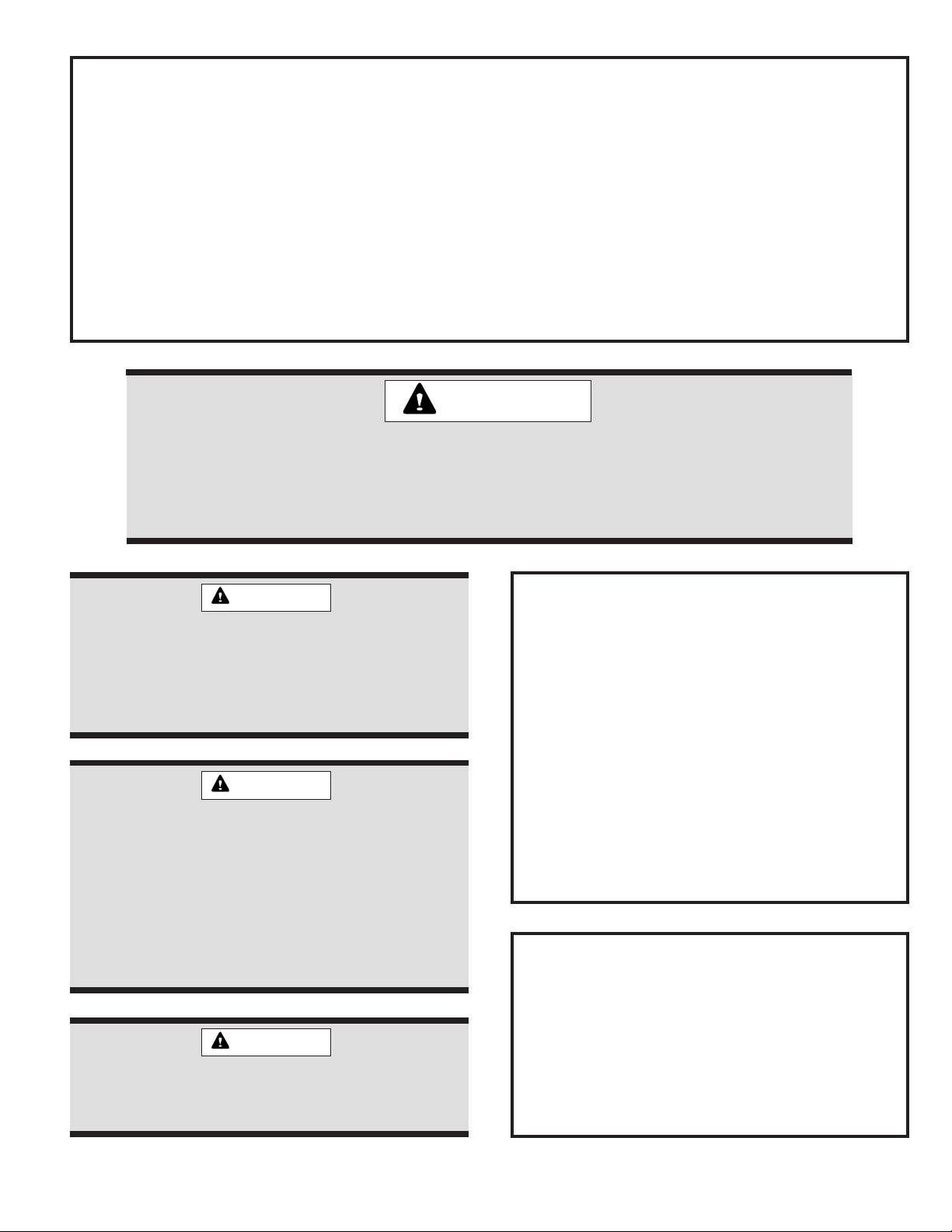
Outdoor units operate under a wide range of weather
conditions; therefore, multiple factors must be considered
when positioning the unit. The unit must be positioned to
give adequate clearances for sufficient airflow and servicing. Refer to Figure 1 for installation clearances.
Installation Clearances
36"
36 *"
36 *"
* A service clearance of 30" must be maintained on
one of the sides adjacent to the control box.
Clearance to one of the other three sides must be
36". Clearance to one of the remaining two sides
may be 12" and the final side may be 6".
A clearance of 24" must be maintained between units.
48" clearance required on top of unit. Maximum soffit
overhang is 36".
36"
swercSenihcaM01#.sbl.ni82
stloBrosserpmoC .sbl.ni09
Table 1
Inspection of Shipment
Upon receipt of equipment, carefully inspect it for possible
shipping damage. If damage is found, it should be noted
on the carrier’s freight bill. Take special care to examine
the unit inside the carton if the carton is damaged. Any
concealed damage discovered should be reported to the
last carrier immediately, preferably in writing, and should
include a request for inspection by the carrier’s agent.
If any damages are discovered and reported to the carrier
DO NOT INSTALL THE UNIT, as claim may be denied.
Check the unit rating plate to confirm specifications
are as ordered.
Figure 1
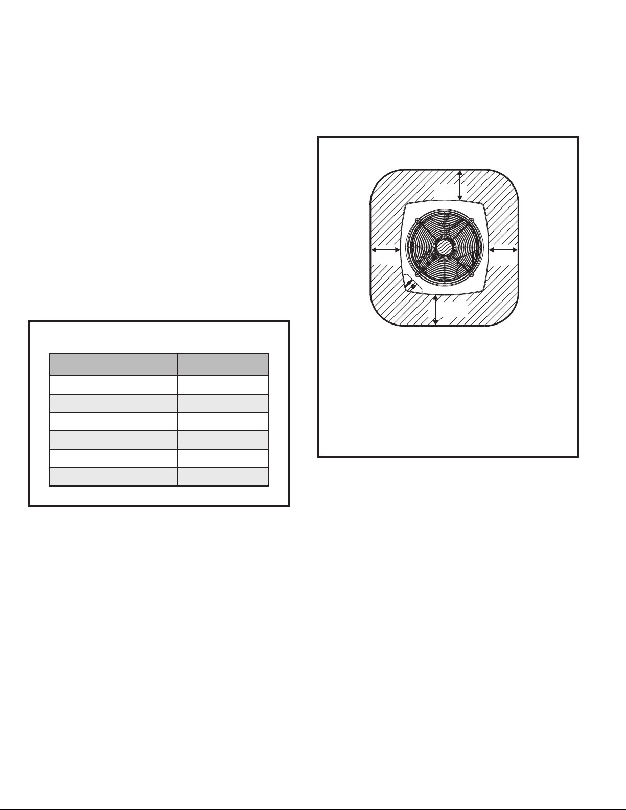
Slab Mounting
When installing unit at grade level, install on slab high
enough above grade to allow adequate drainage of water
(see Figure 2). Top of slab should be located so runoff
water from higher ground will not collect around unit.
Refer to roof mounting section for barrier construction if
unit must face prevailing winter winds.
Roof Mounting
Install unit at a minimum of 4" above surface of the roof.
Care must be taken to ensure weight of unit is properly
distributed over roof joists and rafters. Either redwood or
steel supports are recommended.
If unit coil cannot be mounted away from prevailing winter
winds, a wind barrier should be constructed (see Figure 3).
Size barrier at least the same height and width as the
outdoor unit. Mount barrier 24" from the sides of the unit in
the direction of the prevailing winds.
Page 2 # 48283B006
Page 3
Building
Power
Indoor Unit
Thermostat
Outdoor
Unit
Y1 Outdoor Unit
Heat
Cooling
Indoor Blower
R
W1
Y
G
C
R
W
Y
G
C
C Outdoor Unit
Structure
Slab Mounting
Discharge Air
Mounting Slab
1. Install line voltage power supply to unit from a properly
sized disconnect switch. Any excess high voltage field
wiring should be trimmed or secured away from the
low voltage field wiring.
2. Ground unit at unit disconnect switch or to an earth
ground. To facilitate conduit, a hole is in the bottom of
the control box. Connect conduit to the control box using
a proper conduit fitting. Units are approved for use only
with copper conductors. 24V Class II circuit connections
are made to the low voltage pigtails. A complete unit
wiring diagram is located inside the unit control box
cover (see also pages 16 and 17 of this instruction).
Ground Level
2° or 2" per 5' slope tolerance away from building
structure.
Figure 2
Wind Barrier Construction
Prevailing Winter Winds
Wind Barrier
Inlet Air
Inlet Air
24"
Inlet Air
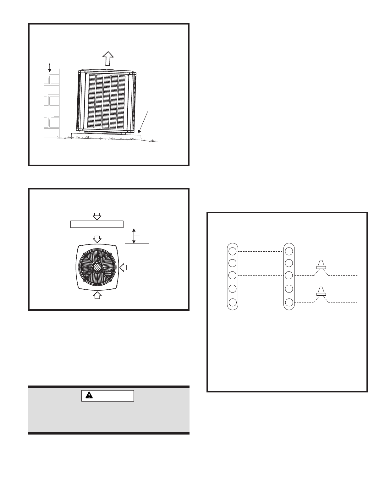
3. Install room thermostat on an inside wall that is not
subject to drafts, direct sunshine, or other heat sources.
4. Install low voltage wiring from outdoor to indoor unit and
from thermostat to indoor unit (see Figure 4).
5. Do not bundle any excess 24V control wire inside control
box. Run control wire through installed wire tie and tighten
wire tie to provide low voltage strain relief and to maintain
separation of field-installed low and high voltage circuits.
Thermostat Designations
Figure 3
Electrical Wiring
All field wiring must be done in accordance with the
National Electrical Code (NEC) recommendations,
Canadian Electrical Code (CEC) and CSA Standards, or
local codes, where applicable.
See unit wiring diagram for power supply connections.
If the indoor unit is not equipped with a blower relay,
one must be field supplied and installed.
Do not connect C (common) connection between
indoor unit and thermostat except when required by
the indoor thermostat. Refer to thermostat installation
instructions. C (common) connection between indoor
unit and outdoor unit required for proper operation.
WARNING
Unit must be grounded in accordance with
national and local codes. Failure to ground unit
properly can result in personal injury or death.
Refer to the furnace or blower coil Installation Instructions
for additional wiring application diagrams and refer to unit
rating plate for minimum circuit ampacity and maximum
overcurrent protection size.
# 48283B006 Page 3
Refrigerant Piping
Field refrigerant piping consists of liquid and suction lines
from the outdoor unit (sweat connections) to the indoor
coil (flare or sweat connections).
Select line set diameters from Table 2 on page 4 to
ensure that oil returns to the compressor. Size vertical
Figure 4
Page 4
suction riser to maintain minimum velocity at minimum
capacity. Recommended line length is 50' or less. If more
than 50' line set is required, contact Technical Services at
(419) 483-4840.
Table 2 shows the diameters for line sets up to 100'
although vertical lift applications and trapping requirements need to be reviewed with Technical Services for
line sets over 50'.
Refrigerant Line Set Diameters (in.)
eniLdiuqiL
eziSdnahtgneLteSeniL
HUTB
.tf21 .tf52 .tf05 .tf57 .tf001
000,818/38/38/38/38/3
000,42 8/3 8/3 8/3 8/3 8/3
000,038/38/38/38/32/1
000,63 8/3 8/3 8/3 8/3 2/1
energy or vibration can be expected. Close attention to
line set isolation must be observed.
Following are some points to consider when placing and
installing a high-efficiency outdoor unit:
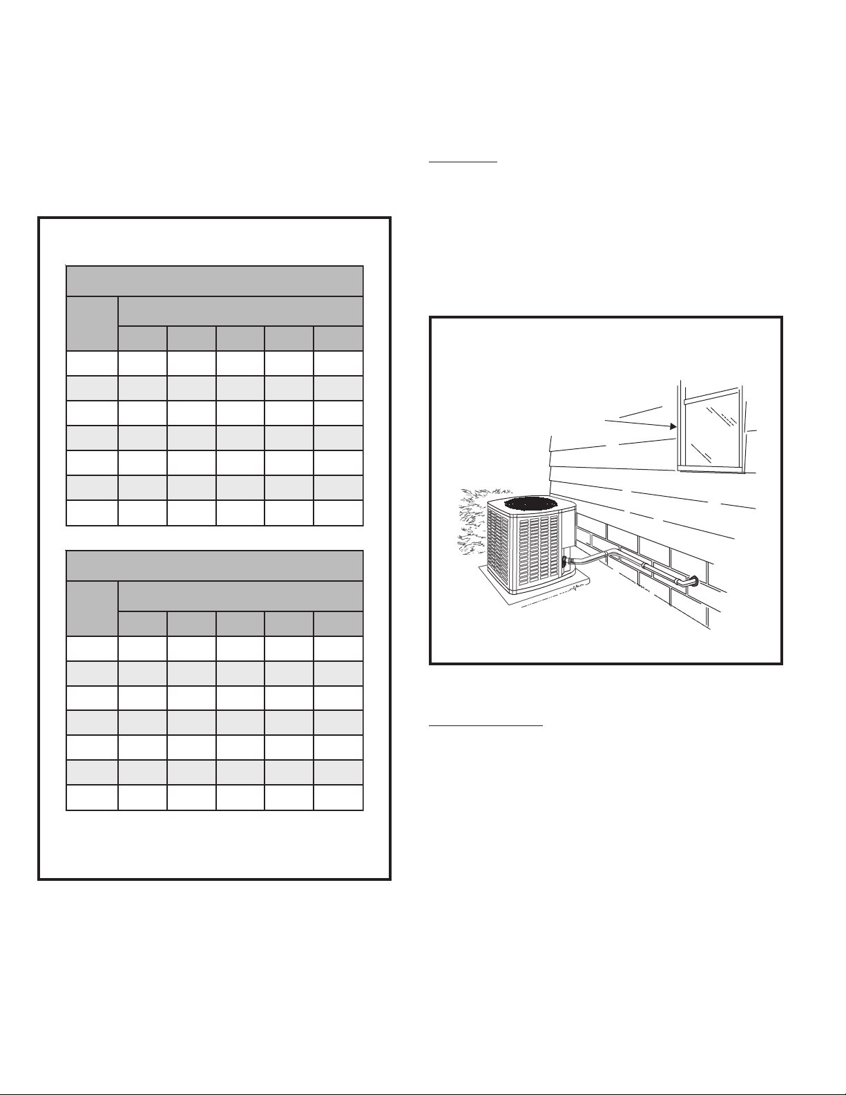
Placement
Be aware that some localities are adopting sound ordinances
based on how noisy the unit is at the neighbor’s home, not at
the original installation. Install the unit as far as possible from
the property line. When possible, do not install the unit
directly outside a bedroom window. Glass has a very high
level of sound transmission. Figure 5 shows how to place the
outdoor unit and line set to reduce line set vibration.
Outside Unit Placement
and Installation
Install unit away
from windows
000,248/38/38/32/12/1
000,84 8/3 8/3 8/3 2/1 2/1
000,068/38/38/32/12/1
eniLnoitcuS
eziSdnahtgneLteSeniL
HUTB
.tf21 .tf52 .tf05 .tf57 .tf001
000,814/34/34/34/34/3
000,42 4/3 4/3 4/3 4/3 8/7
000,034/34/34/38/78/7
000,63 8/7 8/7 8/7 8/7 8/1-1
000,248/78/78/78/1-18/1-1
000,84 8/7 8/7 8/7 8/1-1 8/1-1
000,068/1-18/1-18/1-18/1-18/1-1
For installations exceeding 50', contact
Technical Services at (419) 483-4840.
Two 90° elbows installed in lineset
will reduce lineset vibration
Figure 5
Line Set Isolation
Illustrations on the following pages demonstrate procedures which ensure proper refrigerant line set isolation.
Figure 6 shows how to install line sets on horizontal runs.
Figure 7 shows how to make a transition from horizontal
to vertical. Figure 8 on page 6 shows how to install line
sets on vertical runs.
Brazing Connection Procedure
Table 2
Installing Refrigerant Line
During the installation of an air conditioning system, it is
important to properly isolate the refrigerant line to prevent
unnecessary vibration. Line set contact with the structure
(wall, ceiling, or floor) may cause objectionable noise
when vibration is translated into sound. As a result, more
Page 4 # 48283B006
1. Cut ends of refrigerant lines square (free from nicks
or dents). Debur the ends. The pipe must remain
round; do not pinch end of line.
2. Before making line set connections, use dry nitrogen to
purge the refrigerant piping. This will help to prevent
oxidation and the introduction of moisture into the system.
Page 5
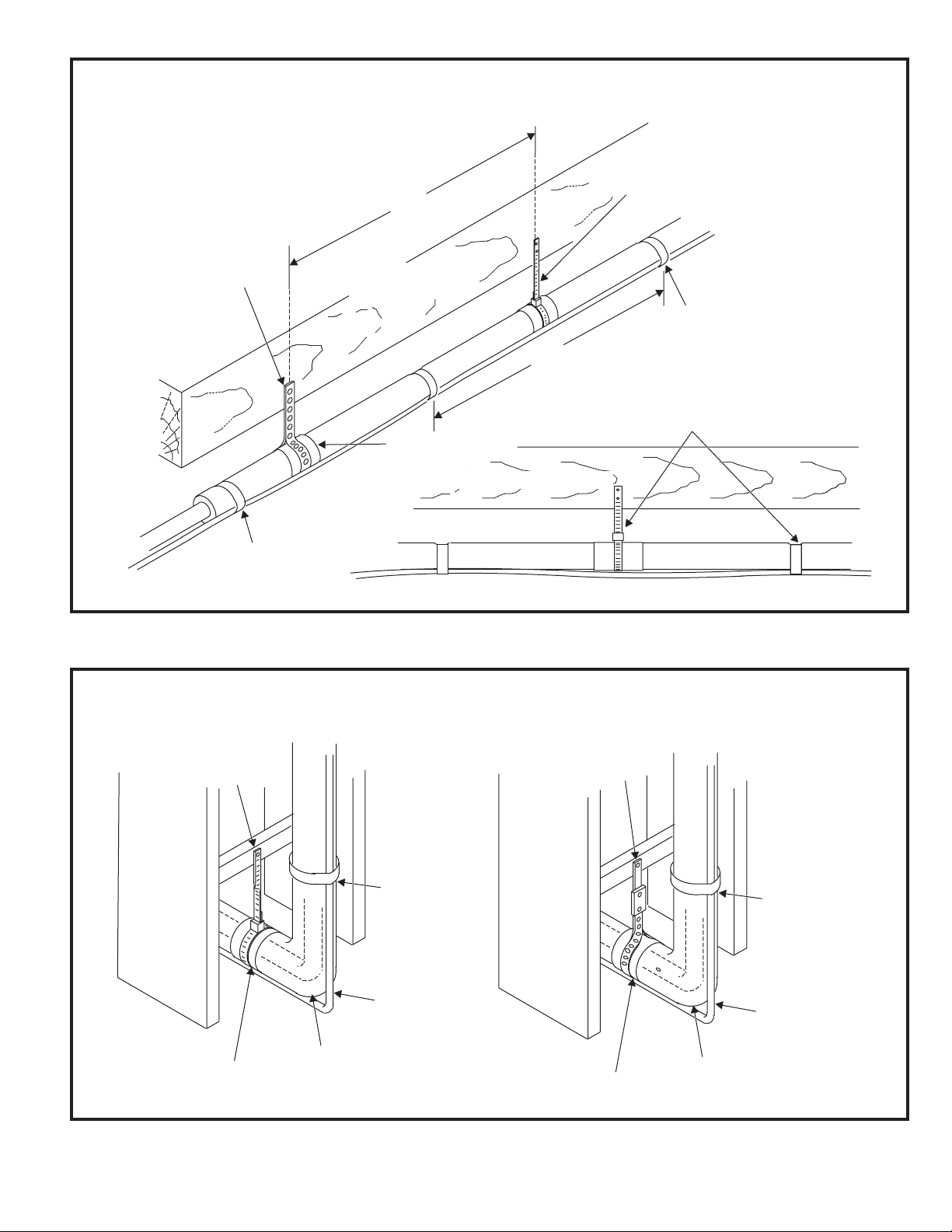
To hang line set from joist or rafter,
use either metal strapping material
or anchored heavy nylon wire ties.
Strapping Material
(around vapor line only)
8’
8’
Tape or Wire Tie
Strap the vapor line to the joist or rafter
at 8 intervals then strap the liquid line
to the vapor line.
’
Floor Joist or
Roof Rafter
Metal Sleeve
Floor Joist or Roof Rafter
Tape or Wire Tie
Wire Tie
(around vapor line only)
Refrigerant Line Sets: Installing Horizontal Runs
Anchored
Heavy Nylon
Wall
Stud
Wire Tie
Metal Sleeve
Figure 6
Refrigerant Line Sets: Transition from Vertical to Horizontal
Automotive
Muffler-Type
Hanger
Strap Liquid
Line to Vapor
Vapor Line Wrapped
–
in Armaflex
Line
Liquid Line
Wall
Stud
Metal Sleeve
Vapor Line Wrapped
–
in Armaflex
Strap Liquid
Line to Vapor
Line
Liquid Line
# 48283B006 Page 5
Figure 7
Page 6
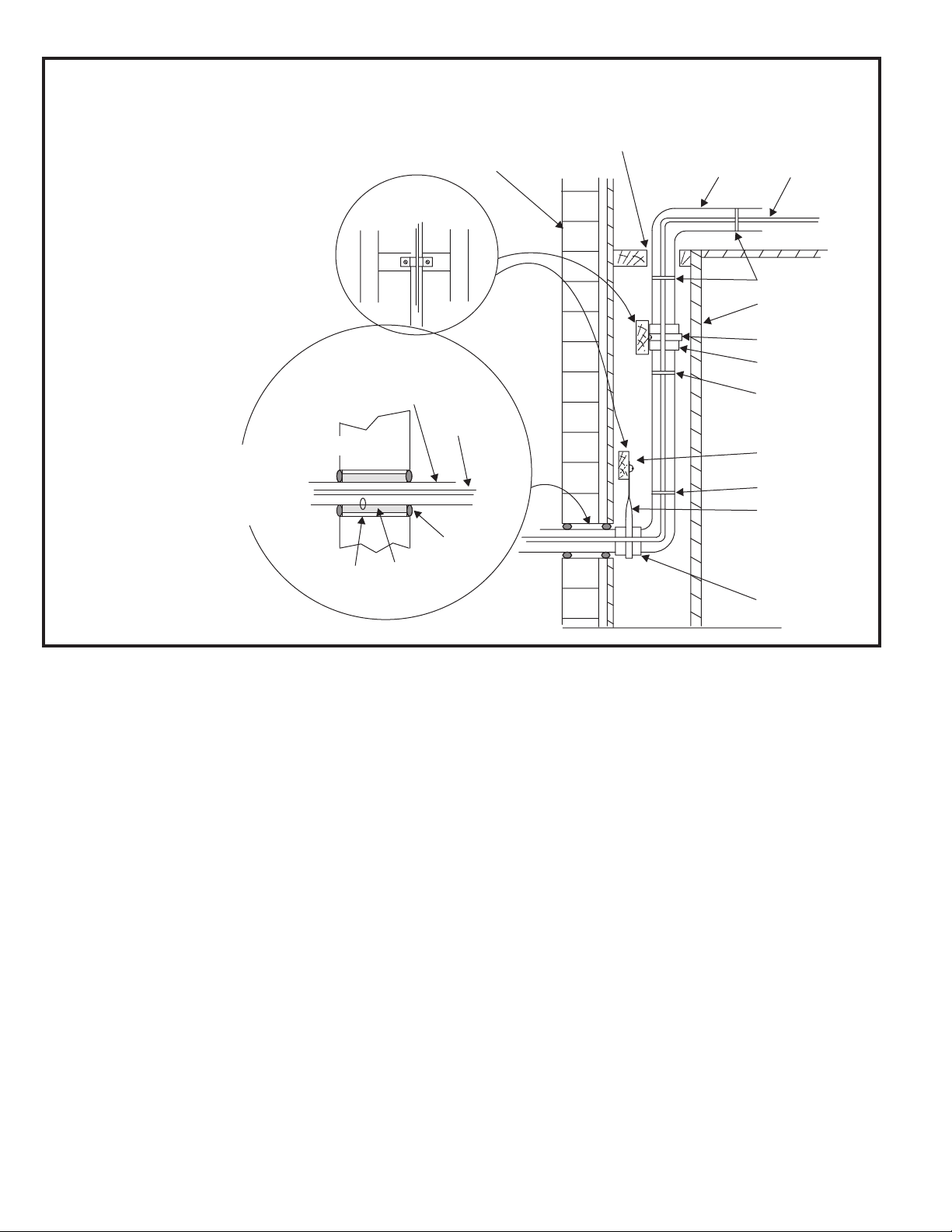
Refrigerant Line Sets: Installing Vertical Runs (new construction shown)
NOTE: Similar installation practices
should be used if line set is to be
installed on exterior of outside wall.
IMPORTANT:
Refrigerant
lines must not
contact structure.
Wood Block
Between Studs
Vapor Line Wrapped
with Armaflex
Outside Wall
Outside Wall
Liquid Line
Caulk
IMPORTANT: Refrigerant
lines must not contact wall.
Vapor Line
Liquid Line
Wire Tie
Inside Wall
Strap
Sleeve
Wire Tie
Wood Block
Wire Tie
Strap
PVC Pipe
Fiberglass
Insulation
Figure 8
3. Use silver alloy brazing rods (5% or 6% silver alloy for
copper-to-copper brazing or 45% silver alloy for
copper-to-brass or copper-to-steel brazing) which are
rated for use with HCFC-22 refrigerant.
4. Remove the Schrader core assemblies before brazing
to protect them from damage due to extreme heat.
Replace the cores when brazing is complete.
5. Wrap a wet cloth around the valve body and copper tube
stub to protect them from heat damage during brazing.
6. Braze the line set to the service valve. Quench the joints
with water or a wet cloth to prevent heat damage to the
valve core and opening port. The tube end must stay
bottomed in the fitting during final assembly to
ensure proper seating, sealing, and rigidity.
7. Install the factory-supplied fixed orifice (or thermal
expansion valve which is sold separately and which is
approved for use with HCFC-22 refrigerant) in the
liquid line at the indoor coil.
Sleeve
Refrigerant Metering Device
2SCU13 units are designed for use with either fixed orifice
or TXV systems. Refer to the appropriate following section
for information on installing the chosen refrigerant metering device.
Fixed Orifice Systems
2SCU13 units are shipped with a fixed orifice refrigerant
metering device. Replace the existing indoor unit fixed
orifice with the orifice supplied with this unit. Place the
supplied fixed orifice sticker on the indoor cabinet after
installation. See Table 3 for the proper fixed orifice size for
each unit. In nonstandard applications, the provided fixed
orifice may not be appropriately sized.
Install the fixed orifice as shown in Figure 9. Do not twist cap
tubes when loosening the seal nut from the orifice housing.
Use wrench to back up the distributor.
Expansion Valve Systems
Expansion valves equipped with Chatleff-type fittings are
available from the manufacturer. See Table 4 for proper
TXV for each unit.
Page 6 # 48283B006
Page 7

Fixed Orifice Data
ledoM
81-31UCS270-484001350.
42-31UCS2 21-484001 260.
03-31UCS291-484001070.
traP
rebmuN
the expansion valve along with a new teflon seal into the
distributor and tighten to 20 – 30 ft. lbs. Use backup
wrench on all wrench flats. Overtightening will crush
llirD
eziS
the teflon seal and may cause a leak.
2. Attach liquid line portion of distributor assembly along
with new teflon seal to the inlet of the expansion
valve. Tighten to 20 – 30 ft. lbs. Use backup wrench
on all wrench flats. Overtightening will crush the
teflon seal and may cause a leak.
63-31UCS2 42-484001 670.
24-31UCS203-484001280.
84-31UCS2 83-484001 190.
06-31UCS254-484001990.
Table 3
Metering Device Installation
3. Connect the external equalizer line to the equalizer
port on the suction line and tighten to 8 ft. lbs.
4. Strap the superheat sensing bulb to the suction header.
If installing an expansion valve on an indoor coil that
previously used a fixed orifice, be sure to remove the
existing fixed orifice. Failure to remove a fixed orifice
when installing an expansion valve to the indoor coil will
result in improper operation and damage to the system.
Manifold Gauge Set
When checking the unit charge, use a manifold gauge set
that is equipped with “low loss” hoses. Do not use a manifold
gauge set with anything other than a “low loss” hose.
Liquid and Suction Line Service Valves
The liquid line and suction line service valves and service
ports are used for leak testing, evacuating, charging, and
checking charge.
Each valve is equipped with a service port which has a
factory-installed Schrader valve (see Figure 10 on page 8).
A service port cap protects the Schrader valve from contamination and serves as the primary leak seal.
Figure 9
To Access the Schrader Port:
1. Remove the service port cap with an adjustable wrench.
TXV Data
2. Connect gauge to the service port.
ledoM
63-,03-,42-,81-31UCS243K62
84-,24-31UCS2 53K62
06-31UCS210M19
Table 4
To install an expansion valve (see Figure 9):
1. Separate the distributor assembly and remove the
piston orifice and used teflon seal. Insert nozzle end of
# 48283B006 Page 7
traP
rebmuN
3. When testing is completed, replace service port cap.
Tighten finger tight, then an additional 1/6 turn.
To Open Liquid or Suction Line Service Valve:
1. Remove stem cap with an adjustable wrench.
2. Use a service wrench with a hex-head extension to
back the stem out counterclockwise as far as it will
go. Use a 3/16" hex head extension for liquid line
service valves and a 5/16" extension for suction line
service valves.
3. Replace the stem cap. Tighten finger tight, then
tighten an additional 1/6 turn.
Page 8

Service Valve
Valve Closed
Ball Type Service Valve
(Valve Open)
Use adjustable wrench. To open, rotate stem
counterclockwise 1/4 turn (90°). To close, rotate
stem clockwise 1/4 turn (90°).
Figure 11
Leak Testing
Valve Open
Figure 10
To Close Liquid or Suction Line Service Valve:
1. Remove the stem cap with an adjustable wrench.
2. Use a service wrench with a hex-head extension to turn
the stem clockwise to seat the valve. Tighten firmly.
3. Replace the stem cap. Tighten finger tight, then
tighten an additional 1/6 turn.
Suction Line (Ball Type) Service Valve
Suction line (ball type) service valves function the same
way as the other valves; the difference is in the construction (see Figure 11).
The ball valve is equipped with a service port with a
factory-installed Schrader valve. A service port cap
protects the Schrader valve from contamination and
serves as the primary seal.
After the line set has been connected to the indoor and
outdoor units, the line set connections and indoor unit
must be checked for leaks.
WARNING
Refrigerant can be harmful if inhaled. Refrigerant
must always be used and recovered responsibly.
Incorrect or irresponsible use of refrigerant can
result in personal injury or death.
WARNING
Never use oxygen to pressurize refrigeration
or air conditioning systems. Oxygen will explode on contact with oil and could cause
personal injury or death.
Using an Electronic Leak Detector
1. Connect the high pressure hose of the manifold
gauge set to the suction valve service port. (Normally
the high pressure hose is connected to the liquid line
port; however, connecting it to the suction ports helps
to protect the manifold gauge set from damage
caused by high pressure.)
Page 8 # 48283B006
Page 9

2. With both manifold valves closed, connect the cylinder of HCFC-22 refrigerant. Open the valve on the
HCFC-22 cylinder (vapor only).
3. Open the high pressure side of the manifold to allow
HCFC-22 into the line set and indoor unit. Weigh in a
trace amount of HCFC-22. (A trace amount is a
maximum of 2 oz. of refrigerant or 3 lbs. pressure.)
Close the valve on the HCFC-22 cylinder and the
valve on the high pressure side of the manifold gauge
set. Disconnect the HCFC-22 cylinder.
4. Connect a cylinder of nitrogen with a pressure regulating valve to the center port of the manifold gauge set.
When using high pressure gas such as nitrogen
for this purpose, be sure to use a regulator that
can control the pressure down to 1 or 2 psig.
5. Adjust nitrogen pressure to 150 psig. Open the valve
on the high side of the manifold gauge set to pressurize the line set and the indoor coil.
Evacuation
Evacuating the system of noncondensables is critical for
proper operation of the unit. Noncondensables are defined
as any gas that will not condense under temperatures and
pressures present during operation of an air conditioning
system. Noncondensables and water vapor combine with
refrigerant to produce substances that corrode copper
piping and compressor parts.
5. Evacuate the line set and indoor unit to a minimum of 500
microns or lower. During the early stages of evacuation, it
is desirable to close the manifold gauge valve at least
once to determine if there is a rapid rise in pressure. A
rapid rise in pressure indicates a relatively large leak. If
this occurs, the leak testing procedure must be repeated.
6. When 500 microns or lower is maintained, close the
manifold gauge valves, turn off the vacuum pump, and
disconnect the manifold gauge center port hose from
the vacuum pump. Attach the manifold gauge center
port hose to a nitrogen cylinder with pressure regulator
set to 150 psig and purge the hose. Open the manifold
gauge valves to break the vacuum in the line set and
indoor unit. Close the manifold gauge valves.
7. Shut off the nitrogen cylinder and remove the manifold
gauge hose from the cylinder. Open the manifold
gauge valves to release the nitrogen from the line set
and indoor unit.
8. Reconnect the manifold gauge to the vacuum pump,
turn the pump on, and continue to evacuate the line
set and indoor unit until 500 microns is maintained
within a 20-minute period after shutting off the
vacuum pump and closing the manifold gauge valves.
9. When the requirements above have been met,
disconnect the manifold hose from the vacuum pump.
Open the service valves to break the vacuum in the
line set and indoor unit.
WARNING
Do not use a compressor to evacuate a system. Avoid deep vacuum operation. Extremely
low vacuums can cause internal arcing and
compressor failure. Danger of equipment
damage. Damage caused by deep vacuum
operation will void warranty.
Use a thermocouple or thermistor electronic vacuum
gauge that is calibrated in microns. Use an instrument that
reads down to 50 microns.
1. Connect the manifold gauge set to the service valve
ports as follows:
• Low pressure gauge to suction line service valve
• High pressure gauge to liquid line service valve
2. Connect micron gauge.
3. Connect the vacuum pump (with vacuum gauge) to
the center port of the manifold gauge set.
4. Open both manifold valves and start vacuum pump.
# 48283B006 Page 9
Page 10

START-UP
If the system is void of refrigerant, clean the system using
the procedure described below.
CAUTION
If unit is equipped with a crankcase heater, it
should be energized 24 hours before unit
start-up to prevent compressor damage as a
result of slugging.
1. Rotate fan to check for frozen bearings or binding.
2. Inspect all factory and field-installed wiring for loose
connections.
3. After evacuation is complete, open liquid line and
suction line service valves to release refrigerant
charge (contained in outdoor unit) into system.
4. Replace the stem caps and secure finger tight, then
tighten an additional 1/6 of a turn.
5. Check voltage supply at the disconnect switch. The
voltage must be within the range listed on the unit
nameplate. If not, do not start equipment until the
power company has been consulted and the voltage
condition corrected.
6. Set thermostat for cooling demand, turn on power to
indoor blower and close the outdoor unit disconnect
switch to start the unit.
1. Use dry nitrogen to pressurize the system and check
for leaks. Repair leaks, if possible.
2. Evacuate the system to remove as much of the
moisture as possible.
3. Use dry nitrogen to break the vacuum.
4. Evacuate the system again.
5. Weigh the appropriate amount of HCFC-22 refrigerant
(listed on unit nameplate) into the system.
6. Monitor the system to determine the amount of
moisture remaining in the oil. Use a test kit to verify
that the moisture content is within the kit’s dry color
range. It may be necessary to replace the filter drier
several times to achieve the required dryness level. If
system dryness is not verified, the compressor
will fail in the future.
The outdoor unit should be charged during warm weather.
However, applications arise in which charging must occur
in the colder months. The method of charging is determined by the unit’s refrigerant metering device and the
outdoor ambient temperature.
Measure the liquid line temperature and the outdoor
ambient temperature as outlined below:
7. Recheck unit voltage with unit running. Power must be
within range shown on unit nameplate.
Refrigerant Charging
Units are factory charged with the amount of HCFC-22
refrigerant indicated on the unit rating plate. This charge is
based on a matching indoor coil and outdoor coil with 15'
line set. For varying lengths of line set, refer to Table 5 for
refrigerant charge adjustment.
Refrigerant Charge Adjustment
teSeniLdiuqiL
retemaiD
.ni8/3.tf5rep.zo3
* If line length is greater than 15 ft., add this amount.
If line length is less than 15 ft., remove this amount.
tsujda.tf5rep.zO
*tesenil.tf51morf
Table 5
1. Connect the manifold gauge set to the service valve
ports as follows:
• Low pressure gauge to suction line service valve
• High pressure gauge to liquid line service valve
2. Close manifold gauge set valves. Connect the center
manifold hose to an upright cylinder of HCFC-22.
3. If room temperature is below 70°F, set the room thermostat to call for heat. This will create the necessary load
for properly charging the system in the cooling cycle.
4. Use a digital thermometer to record the outdoor
ambient temperature.
5. When the heating demand has been satisfied, switch
the thermostat to cooling mode with a set point of
68°F. When pressures have stabilized, use a digital
thermometer to record the liquid and suction line
temperatures.
6. The outdoor temperature will determine which charging method to use. Proceed with the appropriate
charging method.
Page 10 # 48283B006
Page 11

Charge Using Weigh-In Method (Fixed Orifice/TXV
Systems)
If the system is void of refrigerant, or if the outdoor ambient
temperature is cool, first locate and repair any leaks then
use the weigh-in method to charge the unit.
1. Recover the refrigerant from the unit.
Subcooling Values for
Fixed Orifice or TXV Systems
roodtuO
.pmeT
F°
81- 42- 03- 63- 24- 84- 06-
)F°1±(gniloocbuSdiuqiL
2. Conduct a leak check, then evacuate as previously
outlined.
3. Weigh in the charge according to the total amount
shown on the unit nameplate.
If weighing facilities are not available or if unit is being
charged during warm weather, follow one of the other
procedures outlined below.
Charge Using Subcooling Method (Fixed Orifice/TXV
Systems) – Outdoor Temperatures 65°F or Above
If charging a fixed orifice or TXV system when the outdoor
ambient temperature is 65°F or above, the subcooling
method can be used to charge the unit.
1. With the manifold gauge hose on the liquid service
port and the unit operating stably, use a digital thermometer to record the liquid line temperature.
2. At the same time, record the liquid line pressure reading.
3. Use a temperature/pressure chart for HCFC-22 to
determine the saturation temperature for the liquid line
pressure reading.
4. Subtract the liquid line temperature from the saturation temperature (according to the chart) to determine
subcooling.
56313174151931
57 01 11 5 31 31 9 21
588015 11119 11
59 7 01 4 9 9 9 01
5016938799
511 3 6 2 6 5 8 8
Table 6
3. Use a temperature/pressure chart for HCFC-22 to
determine the saturation temperature for the suction
line pressure reading.
4. Subtract the saturation temperature (according to the
chart) from the suction line temperature to determine
the superheat.
_____ ° Suction Line Temperature °F
–
_____ ° Saturation Temperature °F
=
_____ ° Superheat Value °F
5. Compare the superheat value with those shown in
Table 7 on page 12. If superheat is greater than
shown, add some refrigerant. If superheat is less than
shown, recover some refrigerant.
_____ ° Saturation Temperature °F
–
_____ ° Liquid Line Temperature °F
=
_____ ° Subcooling Value °F
5. Compare the subcooling value with those shown in
Table 6. If subcooling is greater than shown, recover
some refrigerant. If subcooling is less than shown,
add some refrigerant.
Charge Using Superheat Method (Fixed Orifice
Systems) – Outdoor Temperatures 65°F or Above
1. With the manifold gauge hose on the suction service
port and the unit operating stably, use a digital thermometer to record the suction line temperature.
2. At the same time, record the suction line pressure
reading.
# 48283B006 Page 11
Charge Using Approach Method (TXV Systems)
– Outdoor Temperatures 65°F or Above
The following procedure is intended as a general guide
and is for use on expansion valve systems only. For best
results, indoor temperature should 70°F to 80°F. Monitor
system pressures while charging.
1. Record outdoor ambient temperature using a digital
thermometer.
2. Attach high pressure gauge set and operate unit for
several minutes to allow system pressures to stabilize.
3. Compare stabilized pressures with those provided in
Table 9 on page 13. Minor variations in these pressures may be expected due to differences in installations. Significant differences could mean that the
system is not properly charged or that a problem
exists with some component in the system.
Page 12

Superheat Values for
Fixed Orifice Systems
(80°DB/67°WB Return Air)
Approach Values for TXV Systems
ledoM 81- 42- 03- 63- 24- 84- 06-
.pmeTtneibmAroodtuO
F°
0683
56 53
0703
57 62
0822
58 81
0921
59 8
0015
501 0
taehrepuS
F°
Table 7
Pressures higher than those listed indicate that the
system is overcharged. Pressures lower than those
listed indicate that the system is undercharged. Verify
adjusted charge using the approach method.
.pmeT
601119558
F°
Approach value is the liquid line temperature
minus the outdoor ambient temperature (±1°F).
NOTE: For best results, use the same digital
thermometer to check both outdoor ambient and
liquid temperatures.
Table 8
4. Use the same digital thermometer to check liquid line
temperature.
5. Subtract the outdoor ambient temperature from the
liquid line temperature to determine the approach
temperature.
_____ ° Liquid Line Temperature °F
–
_____ ° Outdoor Ambient Temperature °F
=
_____ ° Approach Temperature °F
6. Compare the approach value with those shown in
Table 8. If the values to do not agree with those
provided in Table 8, add refrigerant to lower the
approach temperature or recover refrigerant from the
system to increase the approach temperature.
Check Charge Using Normal Operating Pressures
Use Table 9 to perform maintenance checks. Table 9 is
not a procedure for charging the system. Minor variations
in these pressures may be due to differences in installations. Significant deviations could mean that the system is
not properly charged or that a problem exists with some
component in the system.
Page 12 # 48283B006
Page 13

Normal Operating Pressures
ledoM
lioCroodtuO
riAgniretnE
erutarepmeT
F°5614108741971416754147341875410815167
F°5766118371087617707167761080711877187
F°5859128812285918710277891188912870297
F°5922238432287220843287132280324804208
F°50185258762480621886297862485625877218
F°51149268703589923890318803583036881338
F°56 441 37 741 86 041 66 051 76 741 07 541 07 051 76
F°57 761 87 371 47 661 17 671 27 171 57 071 57 771 27
F°58 691 28 302 97 691 67 502 67 891 87 891 08 702 77
81- 42- 03- 63- 24- 84- 06-
L S L S L S L S L S L S L S
)VXT(evlaVnoisnapxE
)CFR(ecifirOdexiF
F°59 522 48 832 38 722 08 732 97 822 18 032 48 932 08
F°501 652 68 272 68 262 38 372 18 262 48 462 68 472 38
F°511 392 88 713 88 203 68 413 48 003 58 103 88 513 58
L – Liquid S – Suction
Values provided above are typical pressures. Indoor unit matchup, indoor air quality, and indoor load will cause
pressures to vary.
Table 9
# 48283B006 Page 13
Page 14

OPERATION
Outdoor unit and indoor blower cycle on demand from the
room thermostat. When the thermostat blower switch is
moved to the ON position, the indoor blower operates
continuously.
MAINTENANCE
WARNING
Before performing maintenance operations on
system, turn the electric power to unit OFF at
disconnect switch(es). Unit may have multiple
power supplies. Electrical shock could cause
personal injury or death.
Maintenance and service must be performed by a qualified installer or service agency.
At the beginning of each cooling season, the system
should be checked as follows:
1. Clean and inspect condenser coil. Coil may be
flushed with a water hose. Be sure the power is off
before using water to clean the coil.
2. Outdoor fan motor is pre-lubricated and sealed. No
further lubrication is needed.
3. Visually inspect connecting lines and coils for evidence of oil leaks.
4. Check wiring for loose connections.
5. Check for correct voltage at unit (with unit operating).
6. Check amp-draw outdoor fan motor.
Unit nameplate _________ Actual _________
NOTE – If owner complains of insufficient cooling, the
unit should be gauged and refrigerant charge checked.
Refer to the Refrigerant Charging section on page 10.
Indoor Coil
1. Clean coil, if necessary.
2. Check connecting lines and coils for evidence of oil
leaks.
3. Check condensate pan line and clean, if necessary.
Indoor Unit
1. Clean or change filters.
2. Adjust blower speed for cooling. Measure the pressure
drop over the coil to determine the correct blower CFM.
3. Belt drive blowers: Check belt for wear and proper
tension.
4. Check all wiring for loose connections.
Page 14 # 48283B006
Page 15

5. Check for correct voltage at unit (with unit operating).
6. Check amp-draw on blower motor.
Unit nameplate _________ Actual _________
Start-Up and Performance Checklist
Job Name _______________________________ Job No. ________________ Date ______________
Job Location _____________________________ City ___________________ State ______________
Installer _________________________________ City ___________________ State ______________
Unit Model No.______________ Serial No. ___________________
Service Technician ________________________________________ Nameplate Voltage ______________
Rated Load Ampacity ________ Compressor _______________ Outdoor Fan ___________________
Maximum Fuse or Circuit Breaker ________________________
Electrical Connections Tight? Indoor Filter Clean? Supply Voltage (Unit Off) ________________
Indoor Blower RPM _____________ S.P. Drop Over Indoor (Dry) ____________
Outdoor Coil Entering Air Temperature _____________ Voltage with Compressor Operating _____________
Discharge Pressure ___________ Vapor Pressure ____________
Refrigerant Charge Checked? Outdoor Fan Checked?
Refrigerant Lines: Leak Checked? Properly Insulated?
Service Valves: Fully Opened? Caps Tight?
Thermostat: Calibrated? Properly Set? Level?
# 48283B006 Page 15
Page 16

OUTDOOR
FAN
RED
PURPLE
BLACK
ORANGE
YELLOW
DUAL
CAPACITOR
C
F
H
RED
A4
TIMED OFF
CONTROL
(IF USED)
3
2
1
TO 24 VAC
POWER SOURCE
20 VA MINIMUM
NEC CLASS 2
Y1
C
RSC
COMPRESSOR
CRANKCASE HEATER
(IF USED)
L1
1
208-230/60/1
L2
HR1
EQUIPMENT
GROUND
FOR USE WITH COPPER CONDUCTORS ONLY. REFER TO UNIT RATING
1
PLATE FOR MINIMUM CIRCUIT AMPACITY AND MAXIMUM OVERCURRENT
PROTECTION SIZE.
WARNING-ELECTRIC SHOCK HAZARD, CAN CAUSE INJURY OR DEATH.
UNIT MUST BE GROUNDED IN ACCORDANCE WITH NATIONAL
AND LOCAL CODES.
LINE VOLTAGE FACTORY INSTALLED
LINE VOLTAGE FIELD INSTALLED
24 VOLT FACTORY INSTALLED
CLASS II VOLTAGE FIELD INSTALLED
BLACK
COMPRESSOR
CONTACTOR
GROUND
LUG
BLACK
K1-1
YELLOW
RED
H
RED
C
C12
C
ORANGE
BLACK
F
SR
PURPLE
B4
B1
L2
208-230/60/1
GROUND
S4 HIGH
PRESSURE
SWITCH
(IF USED)
S4
K1
POWER SOURCE
DESCRIPTION
KEY COMPONENT
A4 CONTROL - TIMED OFF
B1 COMPRESSOR
B4 MOTOR - OUTDOOR FAN
C12 CAPACITOR - DUAL
HR1 HEATER - COMPRESSOR
K1-1 CONTACTOR - COMPRESSOR
S4 SWITCH - HIGH PRESSURE
S24 SWITCH - LOSS OF CHARGE
L1
S24 LOSS
OF CHARGE
SWITCH
(IF USED)
A4
S24
2
3
1
Y1
C
TO 24 VAC
20 VA MINIMUM
NEC CLASS 2
Single Phase Wiring Diagram P/N 48352-001
Figure 12
Page 16 # 48283B006
Page 17

B4
OUTDOOR
FAN
PURPLE
BLACK
ORANGE
BLACK
BLACK
C1
OUTDOOR FAN
CAPACITOR
RED
A4
TIMED OFF
CONTROL
(IF USED)
2
31
TO 24 VAC
POWER SOURCE
10 VA MINIMUM
NEC CLASS 2
C
Y1
COMPRESSOR
FOR USE WITH COPPER CONDUCTORS ONLY. REFER TO UNIT RATING
1
PLATE FOR MINIMUM CIRCUIT AMPACITY AND MAXIMUM OVERCURRENT
PROTECTION SIZE.
B1
CRANKCASE HEATER
(IF USED)
HR1
208-230/60/3
L1
1
L2
L3
EQUIPMENT
GROUND
HR1
GROUND
BLACK
COMPRESSOR
CONTACTOR
LUG
S40
K1-1
S40
K1
T3
L3
BLACK
T2
L2
BLACK
BLACK
RED
C1
PURPLE
T1
L1
ORANGE
B4
BLACK
B1
208-230/60/3
S4 HIGH
PRESSURE
SWITCH
(IF USED)
K1
1
L1
L2
L3
GROUND
2
S24 LOSS
OF CHARGE
SWITCH
(IF USED)
A4
S4
POWER SOURCE
10 VA MINIMUM
NEC CLASS 2
S24
2
3
1
C
Y1
TO 24 VAC
2
JUMPER IS USED WHEN TOC IS NOT USED.
DESCRIPTION
KEY COMPONENT
WARNING-ELECTRIC SHOCK HAZARD, CAN CAUSE INJURY
OR DEATH. UNIT MUST BE GROUNDED IN
ACCORDANCE WITH NATIONAL AND LOCAL CODES.
A4 CONTROL - TIMED OFF
B1 COMPRESSOR
B4 MOTOR - OUTDOOR FAN
C1 CAPACITOR - OUTDOOR FAN
HR1 HEATER - COMPRESSOR
LINE VOLTAGE FACTORY INSTALLED
LINE VOLTAGE FIELD INSTALLED
24 VOLT FACTORY INSTALLED
CLASS II VOLTAGE FIELD INSTALLED
K1-1 CONTACTOR - COMPRESSOR
S4 SWITCH - HIGH PRESSURE
S24 SWITCH - LOSS OF CHARGE
S40 THERMOSTAT - CRANKCASE
Three Phase Wiring Diagram P/N 48436-001
Figure 13
# 48283B006 Page 17
Page 18

Limited Warranty
August 1, 1997
This warranty gives you specific legal rights and you may have other rights
which vary from state/province to state/province.
Warrantor: Armstrong Air Conditioning Inc., 421 Monroe St., Bellevue, OH 44811
Armstrong Air Conditioning Inc. products are available under the following names: Air Ease, Armstrong Air, American Aire, Concord
Subject to the limitations stated in this warranty, we warrant to the first buyer for use the residential heating, cooling or heat pump unit, when
installed, operated and maintained as required by this warranty, to be free of defects in workmanship or material for a period of 5 years
(1 year for commercial equipment) from the time of installation. We will replace any defective component without cost or expense to you
except for the costs of delivery and labor for removal and replacement of the defective component.
The 2SCU13LB Series air conditioners carry a 5-year compressor warranty. The 2SCU13LE Series air conditioners carry a 10-year
compressor warranty.
Warranty Begins
The warranty period begins when the installation is complete and the product is ready to operate. You must be able to verify this date
whenever a warranty claim is made. Original bill of sale, installer’s invoice or other similar document will suffice. If the beginning date
cannot be verified, we will consider warranty coverage to begin 6 months after the date the product was shipped from our factory.
Limitations on Implied Warranties
Implied warranties of merchantability or, to the extent applicable, fitness for a particular purpose are limited to 5 years, the same duration
as the basic limited written warranty provided herein. Some states/provinces do not allow limitations on how long an implied warranty of
merchantability or fitness lasts, so the above limitations or exclusions may not apply to you.
Only Warranty
This written Limited Warranty is the only warranty made by the warrantor; this warranty is in lieu of and excludes all other warranties,
express or implied. The warrantor does not authorize any person to provide any other warranty or to assume for it any further obligation in
connection with the warranted product.
What is NOT Covered
1. Cabinets or cabinet pieces.
2. Normal maintenance items such as filters, fan belts, fuses or other consumable items.
3. Damage caused by misuse, failure to maintain properly, accidents or acts of God.
4. External wiring, piping, venting or attachment of accessory products not integral to our product, including without limitation,
humidifier, air cleaner, vent damper, thermostat or other mechanical devices not manufactured by the warrantor.
5. Products that have been operated in a corrosive atmosphere where a concentration of acids, halogenated hydrocarbons or
other corrosive elements causes deterioration to metal surfaces or integral components. NOTE: Operation in a corrosive
atmosphere is considered abuse and voids this warranty.
6. Products that have NOT been installed in accordance with our published installation instructions, applicable local, state/
provincial or national codes, ACCA published standards.
7. Products that have NOT been installed by competent, qualified installers.
8. Products that have been moved from their original place of installation.
Warranty on Replacement Components
Any replacement component furnished by us will assume the remaining (unused) portion of the Limited Warranty.
Consequential Damages
The warrantor shall not be responsible for any consequential damages caused by any defect in the product. Some state/provinces do not
allow the exclusion or limitations of incidental or consequential damages, so the above limitation or exclusion may not apply to you.
This product must be installed, used and cared for in accordance with the instruction manual. You are responsible for required periodic
maintenance or service, such as changing or cleaning of air filters and lubrication or cleaning of components. Failure to properly install,
operate or maintain your unit voids this warranty.
Page 18 # 48283B006
 Loading...