

Page 1
2009 Lennox Industries Inc.
Dallas, Texas, USA
INSTALLER’S SYSTEM SETUP
GUIDE
icomfortt Thermostat
Touch Screen Programmable Communicating Thermostat
CONTROLS
506052−01
11/09
Shipping and Packing List1
1 − icomfort Touch Screen Communicating, 7−day Programmable
Thermostat
6 − Mounting Screws
6 − Wall Anchors
1 each − Installation Quick-Start Guide, Installer’s System Setup Guide,
Homeowner’s Manual, Warranty card, Warranty Audit tag
Litho U.S.A.
*2P1109* *P506052-01*
Page 2
Table of Contents
icomfort Thermostat Terms and Acronyms 3. . . . . . . . . . . . . . . . .
icomfort Technical Description 4. . . . . . . . . . . . . . . . . . . . . . . . . . .
icomfort Thermostat Features 5. . . . . . . . . . . . . . . . . . . . . . . . . . .
Installing icomfort Thermostat 5. . . . . . . . . . . . . . . . . . . . . . . . . . .
Installer setup 6. . . . . . . . . . . . . . . . . . . . . . . . . . . . . . . . . . . . . . . . . .
System settings 7. . . . . . . . . . . . . . . . . . . . . . . . . . . . . . . . . . . . .
Setting time and date 8. . . . . . . . . . . . . . . . . . . . . . . . . . . . . . . . .
Add/remove/modify non−communicating devices 9. . . . . . . . .
Modify communicating device settings 10. . . . . . . . . . . . . . . . . .
Indoor air quality controls 12. . . . . . . . . . . . . . . . . . . . . . . . . . . . .
Tests 14. . . . . . . . . . . . . . . . . . . . . . . . . . . . . . . . . . . . . . . . . . . . . . . . . .
Diagnostics 17. . . . . . . . . . . . . . . . . . . . . . . . . . . . . . . . . . . . . . . . . . . .
Alerts 18. . . . . . . . . . . . . . . . . . . . . . . . . . . . . . . . . . . . . . . . . . . . . . . . .
Access installer program from User Home screen 22. . . . . . . . . . . .
Reconfiguring a system 23. . . . . . . . . . . . . . . . . . . . . . . . . . . . . . . . . .
Editable parameters table (user and Installer) 25. . . . . . . . . . . . . . . .
Alarm Codes and Descriptions 31. . . . . . . . . . . . . . . . . . . . . . . . . . . .
Wiring Diagrams 36. . . . . . . . . . . . . . . . . . . . . . . . . . . . . . . . . . . . . . . .
WARNING
Always turn off power at the main power source by switching the
circuit breaker to the OFF position before installing or removing
this thermostat.
All wiring must conform to local and national building and electrical codes and ordinances.
Do not switch system to cool if the outdoor temperature is below
45°F (7°C). This can damage the cooling system.
CAUTION
This is a 24VAC low−voltage thermostat. Do not install on voltages higher than 30VAC.
Do not short (jumper) across terminals on the gas valve or at the
system control to test installation. This will damage the thermostat and void the warranty.
IMPORTANT
Read this manual before programming this thermostat.
Use this thermostat only as described in this manual.
506052−01 11/09
Page 2
Page 3

icomfortt Thermostat Terms and Acronyms
Subnet Controller (SC): (part of the communicating thermostat) Local
device that controls the system.
Subnet: A part of the communication network that contains devices to
control one functional HVAC system.
RSBus − Residential Serial Bus − the means for transmitting data within
the communicating system.
Controller Area Network Protocol: Rules for networking, for transmission and receipt of information between communicating systems.
Baud Rate: Maximum speed of BUS 40K baud.
Byte: 8 bits of information transmitted on the RSBus.
Integrated Furnace Control (IFC): Communicating control for furnace.
IFC controls ignition, CAI, blower, and monitors all safety features in the
unit.
Air Handler Control (AHC): Communicating control for air handler
units. AHC controls operation of blower, heat strips, and monitors all
safety features in the unit.
HP Control (Defrost Control) (UC): Communicating defrost control.
UC controls low and high speed compressor operation, defrost opera-
tions, fan motor, and reversing valve and monitors all safety features in
the unit.
AC Control: Communicating air conditioning control. AC controls low
and high speed compressor operation, fan motor operation, and all safety monitors in the unit.
Discharge Air Sensor (DAS): Communicating discharge air sensor.
Provides discharge air temperature to Bus, UI, and IFC for proper operation of equipment.
R: 24V power
C: 24V common
i+: + data information connection
i−: − data information connection
Configuration: Function that accrues during setup of system to identify
other communicating devices. Configuration is also used in setup of a
variable capacity furnace to properly set furnace parameters.
Memory Fault Recall: Method of checking for errors
Firmware: Software stored on a memory chip instead of being part of a
program
Software: Programming and applications for computer
Page 3
icomfort Touch Screen 7−Day Programmable Thermostat
Page 4
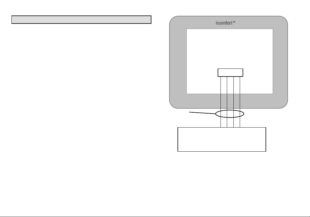
icomfortt Technical Description
The 24VAC icomfort thermostat stores system parameters and settings in a nonvolatile memory (i.e., it retains data when electrical power
fails or is turned off). The thermostat (see figure 1) also:
includes on-board help screens,
supports heat pumps or non−heat pump units, with up to 4 stage
heat / 2 stage compressor operation. (2 stages of heat pump heating and 2 stages of auxiliary backup heat are provided. Also, 2
stages of emergency heat are provided),
supports Indoor Air Quality with time-based notification of consum-
ables including media filters, UVC bulbs, humidifier pads, and
PureAir catalyst service / replacement,
supports variable capacity / multistage heat/cool, universal com-
patibility (gas/electric/heat pump/ac), and is dual fuel capable with
two balance points.
Important
Always use correct software version as recommended for replacement
configuration (discovery).
Connections to non communication outdoor units and all accessories is
described in the Quick−Start Installation guide. (Wiring diagrams are also
shown beginning on Page 36.)
Thermostat
connections
R I+ I − C
RSBUS
Minimum wire size is
18 gauge
icomfort Outdoor Units Control
icomfort Furnace Control
icomfort Air Handler Control
External Sensors − outdoor temperature and humidity
Humidify control
Dehumidify control
Figure 1. icomfort thermostat system
Maximum total length
of all connections on
the RSBus is limited
to 1500ft.
506052−01 11/09
Page 4
Page 5

icomfortt Thermostat Features
Thermostat Type
Electronic communicating, color display touch screen, 7−day programmable.
Supports
Humidification Measurement and Control,
Dew Point Adjustment Control,
Dehumidification Measurement and Control,
Humiditrol® Enhanced Dehumidification Accessory (EDA),
Multi-stage HVAC Systems,
Equipment Maintenance Reminders.
On-board Help Screens.
The icomfort thermostat’s autochangeover mode permits control of
heating, cooling, humidification, and dehumidification without user involvement.
Outdoor Temperature Sensor
Communicating outdoor units contain a built in outdoor temperature sensor.
Installing icomfortt thermostat
Refer to the Quick Start Guide for all the information about installing the
thermostat to a wall and for wiring diagrams for connecting the thermostat to the system using one of a number of possible configurations.
(Wiring diagrams are also shown beginning on Page 36.)
After all the wiring is in place, apply power to the system. 24VAC will begin to power up the thermostat.
Continue with the Installer setup that follows.
Page 5
icomfort Touch Screen 7−Day Programmable Thermostat
Page 6
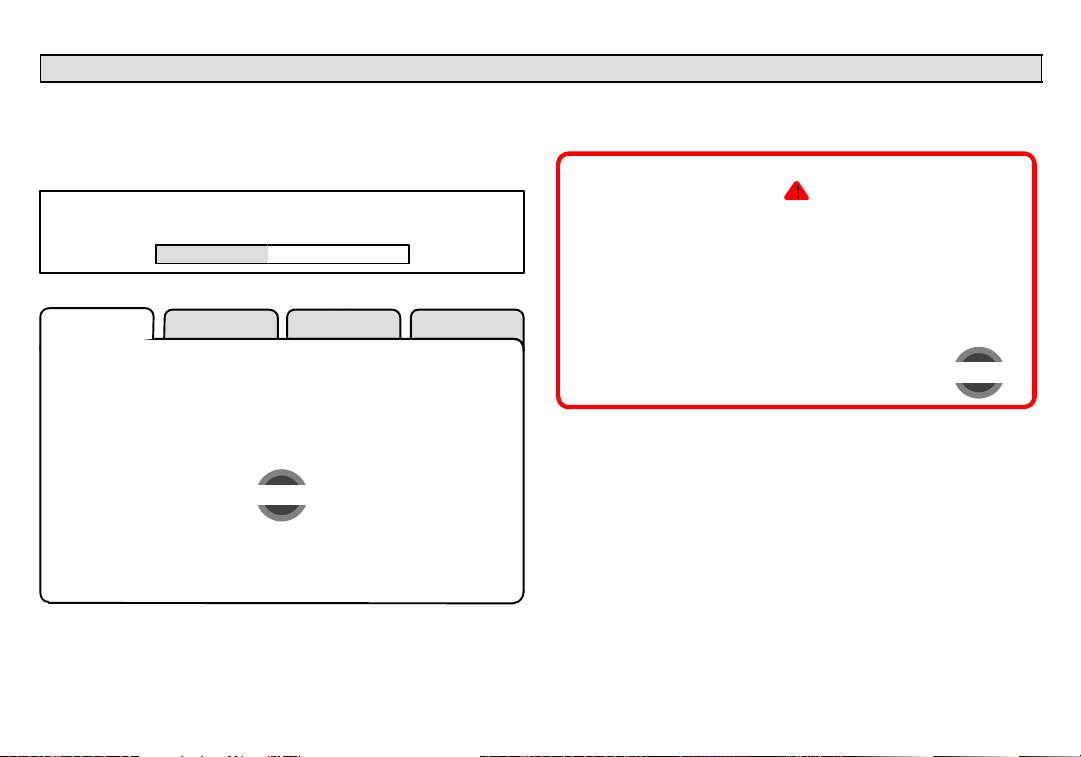
Installer setup − Page 1 of 8
After power is applied to the thermostat for the first time, the processor
checks the system for installed communicating devices, the System
discovery" screen (figure 2) is displayed on the thermostat; followed by
the Use this thermostat" screen (figure 3). Press press here to continue.
SYSTEM DISCOVERY IN PROGRESS
Figure 2. System discovery
setup HELP
tests
During the setup process, alerts may pop open to inform the installer
some item of information that affects the setup (figure 4). Tend to any
such alerts prior to continuing setup.
critical alert
Active
Critical Alert Code: 31
AIR HANDLER reports:
Lost Communication with
THERMOSTAT −
Latest occurrence: 8/23/09
1:57 PM
press for more
close
506052−01 11/09
Thermostat 1
Use this Thermostat?
press here
Figure 3. Use this thermostat screen
Figure 4. Alert window
Page 6
Page 7
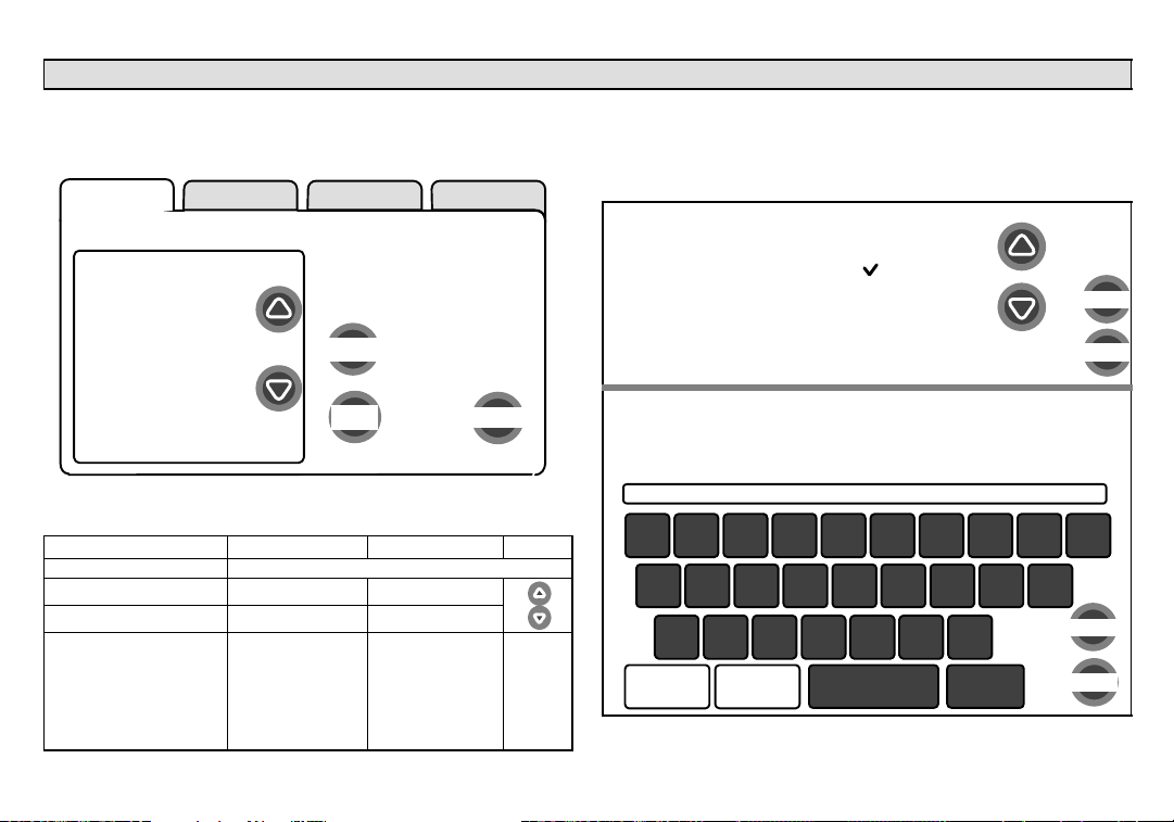
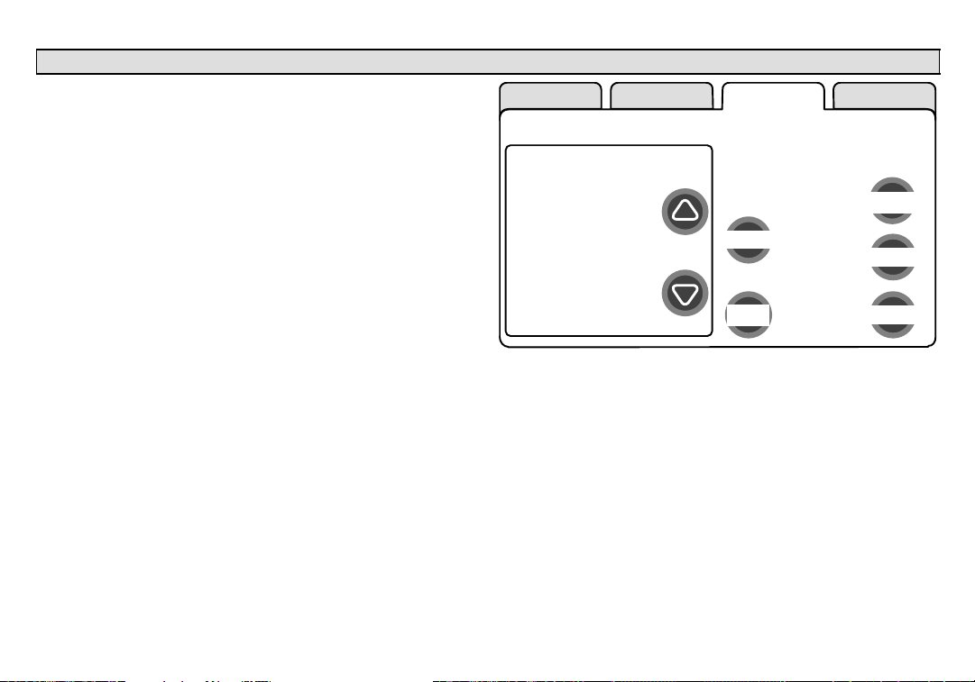
System settings (figure 5) appear first. As you use the up/down arrows
to scroll through the settings, the right hand side will show the current
value, for example, Current Value: (35% ) shows the current setting of
the Circulate Fan ON time.
setup HELP
system settings
Time and Date
Daylight Saving
Time
To view/edit a setting,
highlight it, then press edit.
Current Value:
(35%)
Circulate Fan ON
time
edit
Dealer Name
Dealer Address
Dealer Phone
Number
back
next step
Dealer Email
Figure 5. System settings
The following shows the range/condition and defaults for the settings.
system setting range/condition default use
Time and Date see Page 8
Daylight Saving Time Enabled/Disabled Enabled
Circulate Fan ON Time 15 to 45 35%
Dealer Name
Dealer Address
Dealer Phone Number
Dealer Email
Dealer Website
(alpha−numeric
characters)
Lennox
1−800−9−LENNOX
www.lennox.com
use type
writer to
change
Installer setup − Page 2 of 8
If you want to modify a setting, use one of the tools shown in figure 6.
(Make time and date as described on Page 8.) After changes have
been made, use save to store the changed data or cancel to exit the
screen and return to the list of settings.
up/down arrows
scroll through a
numeric range for
some settings
typewriter tool to input
names, address, phone
numbers etc.
Lennox Repairman
21
qwe
@!
asd
−
*
zxc
symbols
CAPS
ON
Figure 6. Settings change tools
Daylight Saving Time
Enabled
Disabled
Dealer Name
43658709
r
ityu po
$#^%(&)
f
_
v
+
=
bnm
space
/
kghj l
.
back
space
cancel
save
cancel
save
Page 7
icomfort Touch Screen 7−Day Programmable Thermostat
Page 8
Installer setup − Page 3 of 8
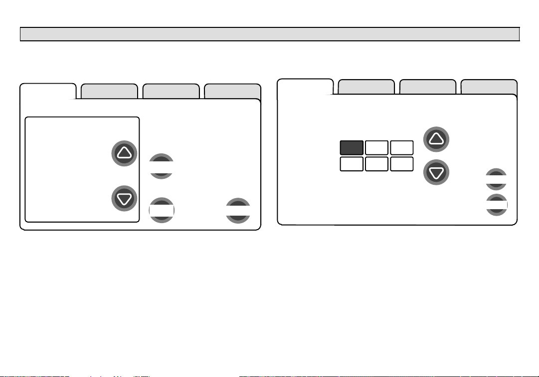
Setting time and date
Use the arrows to select Time and Date; press edit (see figure 7). Press
next to proceed to the Set current time and date" screen (figure 8).
setup HELP
system settings
Time and Date
Daylight Saving
Time
Circulate Fan ON
time
Dealer Name
Dealer Address
Dealer Phone
Number
Dealer Email
tests
to adjust a setting, highlight
it, then press edit.
Current Value:
(September 15, 2009,
09:23 AM)
edit
back
next step
Press other boxes and adjust with the arrows for all time and date
information. When the date and time is correct, press save to save
settings and return to previous settings screen.
setup HELP
Time and Date
10 :19 AM
adjust
Oct 15 2009
cancel
save
Figure 7. View/edit time and date
When the Time and Date" screen appears, enter the correct date as follows:
Press one of the time and date boxes − the text will change to white
type in a dark box (for example, press the 10" box in figure 8).
Press the up/down arrows to change the data.
506052−01 11/09
Figure 8. Set current time and date
NOTE − After setting the time and date, if you don’t need to add any non−
communicating devices, you may wish to accept the default system parameters and skip forward to tests". To do so, repeatedly press next
step on each screen until you get to the tests screen. From there, you
can check the systems operation. Thereafter, should you need to
change a communicating device parameter, access those settings by
pressing the equipment tab in the installer section.
Page 8
Page 9
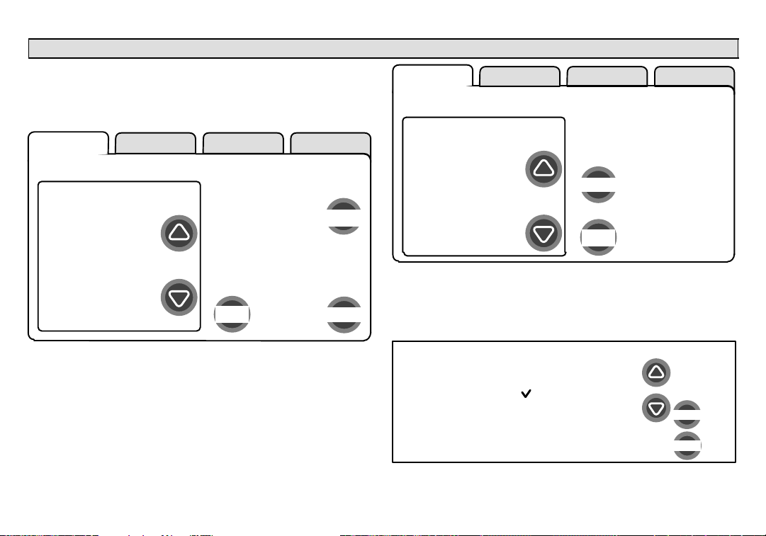
Add/remove/modify non−communicating devices
From this screen (figure 9), use the yes button to access a list of non−
communicating devices for installing or removing. A list similar to that
shown in figure 10 will appear.
setup HELP
system devices
HP
XP19−060−230−06
5809K00015
AIR HANDLER
CBX32MV−60
5809K00020
THERMOSTAT
49W95
A109K00139
SYSTEM
Add or Remove
Non−communicating
equipment?
yes
next stepback
Figure 9. Add/remove/modify non−communicating devices
Humidification / Dehumidification Control Modes depend on a humidifier and/or dehumidifier being added to the system. Therefore, you
must press yes on the button near "Add or Remove Non−communicating
equipment?" Also, in order for the user’s display to show these controls,
the system controls must be set. See Page 12 for more information.
Use the up/down arrows (see figure 10) to select a setting. The right hand
side of the screen indicates what is currently selected, for example, Cur-
rent Value: (Not Installed); press edit if you want to modify that setting.
Installer setup − Page 4 of 8
setup HELP
non−communicating
device list
HUMIDIFIER
DEHUMIDIFIER
UV LIGHT
Figure 10. Installing UV Light
A typical Installed status screen (Figure 11) shows if the device is not
installed or type of equipment installed. Use the arrows to change and
use save to save the change. (Cancel goes pack to previous screen.)
Installed Status
Not Installed
UV LIGHT
Figure 11. Typical non−communicating device edit screen
to adjust a setting, highlight it,
then press edit
Current Value:
(Not Installed)
edit
back
cancel
save
Page 9
icomfort Touch Screen 7−Day Programmable Thermostat
Page 10
Installer setup − Page 5 of 8
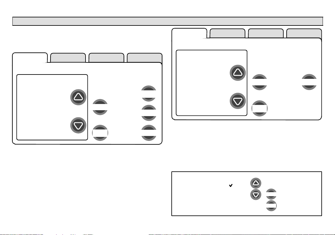
Modify communicating device settings
Use this screen (figure 12) to access communicating devices’ settings.
Use back to return to the previous screen or next step to go on.
setup HELP
system devices
HP
XP19−060−230−06
5809K00015
AIR HANDLER
CBX32MV−60
5809K00020
THERMOSTAT
49W95
A109K00139
SYSTEM
Figure 12. Accessing communicating device settings
With one of the devices highlighted, press about, then use arrow keys to
see a list of data about the selected device. If you select reset ALL, and
then confirm, ALL devices will be reset to their factory settings. (You
would see a screen similar to figure 14.)
With one of the devices in figure 12 highlighted, press edit to go to that
device’s list of settings (see figure 13).
Use the up/down arrows to scroll through the device’s settings and observe the right hand side of the screen (figure 13) to see the current setting, for example, Current Value: (Off). Press edit if you want to modify
that setting, or press back to return to the previous screen.
506052−01 11/09
to adjust a device, highlight
it, then press edit
edit
reset ALL
back
next step
about
setup HELP
HP
Equipment Name
Compressor Short
Cycle Delay
Defrost
Termination Temp
Compressor Shift
Delay On/Off
to adjust a setting, highlight it,
then press edit
Current Value:
(Off)
edit
back
Figure 13. Modify communicating device settings
Settings available for the devices are dependant on the components you
have. Shown below is an example of changing the compressor shift
delay on. After using the arrows to select On, press save to save the
changes and return to the previous screen.
Compressor Shift Delay On/Off
On
Off
Page 10
cancel
save
reset
Page 11
If you select reset and then confirm, the highlighted device will be reset
to its factory setting. You would see a screen similar to figure 14, but referencing only the selected device.
Resetting ALL devices to their factory default
settings will cause the system to restart the
setup process. If you want to continue, then
press ’confirm’ or press ’cancel’.
confirm
cancel
Installer setup − Page 6 of 8
After a reset, the device which had its settings reset to
default will display in the system devices screen in red
type. You will be required to highlight the red−type device(s) and use edit (see figure 12) to change, or at
least view the changed settings of the red−type devices .
In the edit mode, the feature list will show the selected
device’s changed features in red type. Use the up/
down arrows to select each red−typed feature and
press edit. Make changes to the settings using the
Edit tools if desired, or at least, press save in each fea-
ture screen. Upon saving, the previous screen will
display and the type will again be black. Press back to
return the Modify communicating device settings
screen.
HP
XP19−060−230−06
5809K00015
AIR HANDLER
CBX32MV−60
5809K00020
Equipment
Name
Electric Heating
Airflow
Low Cooling
Airflow
Low Cooling
Airflow
Figure 14. Reset device confirmation note
At this point press next step to advance to the test controls.
Page 11
icomfort Touch Screen 7−Day Programmable Thermostat
Page 12
Installer setup − Page 7 of 8
Indoor air quality controls
An example of installing UV Light is shown in figure 10, Page 9.
To turn on humidification or dehumidification controls, in addition to
the setup described on Page 9, work from either the setup tab or the
equipment tab to get to the adjustment screen (figure 15). Use the arrows
to highlight the SYSTEM selection. Press edit.
A long list of features are listed on the right of the next screen (see figure
16). Use the arrows to locate Humidification Control Mode and/or De-
humidification Control Mode. Press edit.
Depending on the type of equipment installed, the lists of options may be
different than those shown in figure 17. In order for either or both of these
controls to display, the selected option must be other than Display
Only".
setup tests equipment HELP
system devices
XP19−060−230−06
5809K00015
AIR HANDLER
CBX32MV−60
5809K00020
THERMOSTAT
49W95
A109K00139
SYSTEM
49W95
A109K00139
(to adjust a device, highlight
it, then press edit)
edit
back
Figure 15. Accessing the SYSTEM adjustment screen
about
reset ALL
next step
506052−01 11/09
Page 12
Page 13

setup tests equipment HELP
SYSTEM
Equipment Name
Filter 1 Timer
Selection
.
.
(various)
.
.
Dehumidification
Control Mode
Humidification
Control Mode
(to adjust a setting, highlight
it, then press edit)
Current Value:
(Display Only)
edit
back
reset
Figure 16. SYSTEM adjustment screen
Dehumidification Control Mode
Display Only
Basic
Precision
Humiditrol
(or Auxiliary
Dehumidifier)
cancel
save
Humidification Control Mode
Display Only
Basic
Precision
Dew Point Control
cancel
save
Figure 17. Selecting Dehumidification/Humidification mode
Installer setup − Page 8 of 8
HUMIDIFICATION modes
BASIC & PRECISIONthese modes allow user control of RH between
15 and 45%. These conditions must be met for either mode to operate:
humidification mode has been enabled, and
the unit is in HEAT mode, and
humidification demand exists (24V present at H), and
BASIC mode also requires heat demand exists (Y for HP heat, or W for
gas heat [W may be energized with G de−energized]).
DEW POINT CONTROLDew point adjustment mode will change the
humidification setpoint based on the outdoor temperature and a user−defined dew point adjustment setting.
DEHUMIDIFICATION modes
In BASIC mode, dehumidification occurs if these conditions are met and
signals are present at specific terminals:
dehumidification has been enabled on installer settings, and
the unit is in COOL mode, and
dehumidification demand exists (RH above setpoint), and
cooling demand exists (Y1 energized).
In PRECISION mode, dehumidification occurs if all BASIC conditions
are true, except cooling demand may or may not be present. Maximum
overcool from cooling set point is 2ºF.
HUMIDITROL or AUX. DEHUMIDIFIER mode requires:
outdoor sensor must be installed and setup
dehumidification has been enabled on installer settings, and
the unit is in COOL mode, (or if in AUTO, at least one thermostat cooling
call made prior to the dehumidification demand), and
a dehumidification demand exists (RH above setpoint), and
outdoor temp. below 95°F; indoor temp. above 65°F, and
for HUMIDITROL, Humiditrol comfort adjust parameters as follows:
MAX adj. − Indoor temp > 2°F above heating setpoint
MID adj. − Indoor temp >
MIN adj. − Indoor temp > 2°F below cooling setpoint
Page 13
HEAT SETPOINT+COOL SETPOINT
icomfort Touch Screen 7−Day Programmable Thermostat
2
Page 14

Tests − Page 1 of 1
The tests feature is not available until after setup has been completed
once. After you press next step in the final setup screen, the Select
tests to run" screen (figure 18) appears.
If you re−select the tests tab from any other screen, a message to press
Start button below to begin system testing" appears; press start.
press start button below to begin system testing
start
setup tests equipment HELP
select tests to run
TEST ALL
Blower
HP Heat − 1st
Stage
HP Heat − 2nd
Stage
Defrost Now
Cooling − 1st
Stage
Cooling − 2nd
Stage
select
alerts diagnostics EXIT
selected tests
skip tests
Figure 18. Select tests to run
When the tests screen opens, TEST ALL will be highlighted (but not yet
selected). If you want to run TEST ALL, press select. Note your selection
on the right side says selected test TEST ALL". Also, note there are now
two buttons along the bottom labeled remove and start. Use remove to
deselect a selected test.
If you prefer, run tests one−at−a−time using the arrows to highlight a desired test and then press select.
Press start to begin testing.
setup tests equipment HELP
select tests to run
TEST ALL
Blower
HP Heat − 1st
Stage
HP Heat − 2nd
Stage
Defrost Now
Cooling − 1st
Stage
Cooling − 2nd
Stage
select
alerts diagnostics EXIT
selected tests
TEST ALL
startremove
Figure 19. Start running tests
506052−01 11/09
Page 14
Page 15

Tests − Page 1 of 1
After the tests have been started, the screen will describe which test is
running (see figure 20). After concluding that the results are the desired
results for any test, press next (if using TEST ALL) to proceed to the next
test or done (if running a single test).
TEST ALL example
CURRENT TEST: Blower
Check Blower Operation
cancel
next
single test example
CURRENT TEST: Blower
Check Blower Operation
cancel
done
Figure 20. Typical tests results screens
After pressing done, the Testing finished" screen will appear (see figure
21). At this point, use the EXIT tab (if you are finished with all setup), or
use diagnostics tab (to analyze the system), or use equipment tab (if
you wish to make any changes to device details).
setup tests equipment HELP
The Testing Process is Finished
press the ’tests’ tab to run more tests.
press the ’EXIT’ tab to start normal operation.
alerts diagnostics EXIT
Figure 21. Testing finished screen
Page 15
icomfort Touch Screen 7−Day Programmable Thermostat
Page 16

Equipment − Page 1 of 1
This feature allows the installer to edit details of devices in the system
without having to re−run the setup program. The following appears after
the equipment tab has been selected
press start button below to edit details of devices in
Press start; the Equipment details edit" screen (figure 22) will open.
You may view information about or modify communicating devices as
described earlier in the setup pages, beginning on page 10.
setup tests equipment HELP
system devices
HP
XP19−060−230−
06
5809K00015
AIR HANDLER
CBX32MV−60
5809K00020
THERMOSTAT
49W95
A109K00139
SYSTEM
Figure 22. Equipment details edit
the system
start
back
to adjust a device, highlight
it, then press edit
about
edit
reset ALL
next step
setup tests equipment HELP
SYSTEM
Equipment
Name
Filter 1 Timer
Selection
Filter 2 Timer
Selection
UV Bulb Timer
Selection
Humidifier Pad
Timer Selection
(to adjust a setting, highlight
it, then press edit)
Current Value:
(System)
edit
back
reset
Figure 23. Equipment details edit
Table on Page 25 shows a list of Editable Parameters for the currently
available devices designed to communicate in this system. Other devices and additional parameters may be added at a later date. Check the
unit installation manuals (i.e. furnace, air handler, heat pump, ac unit) for
current information and default parameters.
506052−01 11/09
Page 16
Page 17

If you need to run diagnostics to analyze the system, press the diagnos-
tics tab. The Select device to run diagnostics" screen (figure 24) will
open.
select device to run
diagnostics on
HP
XP19−060−230−
06
5809K00015
AIR HANDLER
CBX32MV−60
5809K00020
run diagnostics on:
select
diagnostics
Figure 24. Select device to run diagnostics
Use the arrow buttons to scroll through the list of items found on the left of
the screen. Then press select. The right side of the screen shows which
item is selected (figure 25). Use start to begin the process. The screen
will show DIAGNOSTICS IN PROGRESS..." briefly, then change to
show the list of values and conditions discovered.
Use the arrow buttons to scroll through the information and take note of
any found to be out of operating range.
Press done when finished with the information and select another device
to diagnose or use EXIT if finished.
select type of device to run
diagnostics on
HP
XP19−060−230−
06
5809K00015
AIR HANDLER
CBX32MV−60
5809K00020
HP
Diagnostics
Line Voltage 220 volts
24VAC Voltage 24 volts
Y1 − Output On
PSC Fan Relay Closed
ECM Fan 1 On
ECM Fan 2 On
Y2 Solenoid On
Figure 25. Running diagnostics
Diagnostics − Page 1 of 1
run diagnostics on:
HP
remove
diagnostics
start
done
Page 17
icomfort Touch Screen 7−Day Programmable Thermostat
Page 18

Alerts − Page 1 of 4
As described earlier on Page 6, alerts may pop up on the screen during
setup. To view alerts otherwise, press the alerts tab. Up to 10 alerts are
stored for recall by the technician.
The left side of the main alert screen shows a list of each communicating
device discovered in the system and includes model and serial number
information. The up/down arrows allow you to scroll through the list of
discovered devices. The selected device is shown in bold lettering.
On the right side of the alert screen, press view active alerts to list all
active alerts for either SYSTEM ALERTS (lists alerts from all communicating devices) or a selected device. If there are no alerts, the display will
show There are no new alerts that require service".
Press view cleared alerts to list previously active alerts that were
cleared by the device or installer. Until at least one alert has been cleared
by the device or the installer, the display will show There are no new
alerts that require service".
System Devices
SYSTEM ALERTS
HP
XP19−060−230−06
5809K00015
AIR HANDLER
CBX32MV−60
5809K00020
THERMOSTAT
49W95
A109K00139
alerts diagnostics EXIT
use the arrows to
select a device
view active
alerts
view cleared
alerts
The first alert will be displayed in the Device alert" screen (figure 27), in
order of:
1. critical first (red icon),
2. service next (yellow icon).
If the information in the alert box exceeds the box size, press press for
more to see the remaining information.
alert description
ALERT 1 of 5
(Service) Alert Code − (0)
(Thermostat) reports:
(Replace Filter 1)
Latest Occurrence
(04/03/09)
(08:45 PM)
(4) Occurrences
press for more
alerts diagnostics EXIT
back
active alerts
remind later
clear
next alert
Figure 27. Device alert
506052−01 11/09
Figure 26. System Devices alerts
Page 18
Page 19

Alerts − Page 2 of 4
Clearing alerts
A critical alert (red icon) identifies a system or device issue that can pre-
vent the system from working properly or at all, and if allowed to run,
could cause damage to the system. The issue raised by the alert must
be addressed before clearing the alert.
Press clear (see figure 27) to request
clearing of a critical alert; then confirm
the request (shown to the right). The device will respond to the request indicating
whether or not the alert can be cleared at
that time. If it cannot be cleared, revisit
the alert issue and make repairs accordingly.
The edit date option is not available for a critical alert.
A service alert (yellow icon) reminds users to service filters, humidifier
pad, UV light and PureAir Air Purification system.
Press clear (see figure 27) to request
clearing of a service alert. If you answer
no to the was action taken" screen
(shown to the right), the alert reappears
and is not cleared. Action must be taken,
either to perform the maintenance required, or instead of clearing, you may
edit the time to again be reminded (described later).
If you press yes to ’was action taken?’, the Set new alert date" screen
(figure 28) appears. You may chose from the list of options or set a custom time (see figure 30).
press ’confirm’ to clear the
alert, or press ’cancel
confirm
was action taken?
yes no
cancel
alert description
ALERT 1 of 5
(Service) Alert Code − (0)
(Thermostat) reports:
(Replace Filter 1)
Latest Occurrence
(04/03/09)
(08:45 PM)
(4) Occurrences
press for more
set time for next reminder
disabled
3 months
6 months
12 months
24 months
custom time
set
select
cancel
Figure 28. Set new alert date
After selecting a time period using either method and pressing set, the
Cleared alert confirmation" screen (figure 29) appears.
alert description
ALERT 1 of 5
(Service) Alert Code − (0)
(Thermostat) reports:
(Replace Filter 1)
Latest Occurrence
(04/03/09)
(08:45 PM)
(4) Occurrences
press for more
the alert was cleared and
moved to alert history.
please press ’done’ to
return to the list of
active alerts.
done
Figure 29. Cleared alert confirmation
Press done to return to the device alert screen (figure 27, page 18).
Page 19
icomfort Touch Screen 7−Day Programmable Thermostat
Page 20

Alerts − Page 3 of 4
Using custom time"
Use Setting custom time" screen (figure 30) to set an exact date and
time for the reminder to appear. Press in one of the boxes to highlight it
and use the up/down arrows to change the value in that box. Repeat for
all boxes. When desired reminder is displayed, press set.
alert description
ALERT 1 of 5
(Service) Alert Code − (0)
(Thermostat) reports:
(Replace Filter 1)
Latest Occurrence
(04/03/09)
(08:45 PM)
(4) Occurrences
press for more
set time for next reminder
10 19 AM
12 19 2009
set
cancel
Figure 30. Setting custom time
Using remind later"
You may chose remind later and select from Remind later options" list
(see figure 31) or set a custom time as described earlier (see figure 30).
alert description
ALERT 1 of 5
(Service) Alert Code − (0)
(Thermostat) reports:
(Replace Filter 1)
Latest Occurrence
(04/03/09)
(08:45 PM)
(4) Occurrences
press for more
set time for next reminder
1 day
1 week
1 month
3 months
custom time
select
cancelset
Figure 31. Remind later options
After selecting a reminder time using the listed options or a custom time,
press set; the Remind later confirmation" screen appears (see figure
32).
alert description
ALERT 1 of 5
(Service) Alert Code − (0)
(Thermostat) reports:
(Replace Filter 1)
Latest Occurrence
(04/03/09)
(08:45 PM)
(4) Occurrences
remind later
set for:
1/19/10 9:49AM
done
Figure 32. Remind later confirmation
Press done to return to the device alert screen (figure 27, page 18).
506052−01 11/09
Page 20
Page 21

View cleared alerts
A history of cleared alerts allows the installer to review the cleared alerts.
This information can help diagnose problems. Use the arrows to (figure
34) select either SYSTEM ALERTS or a devicefrom the list (see figure
34) and press view cleared alerts. Then scroll through the alerts using
next alert (see figure 34). The back button returns to the system devices
alerts screen.
Alerts − Page 4 of 4
If no alert or only one alert is present in the history of cleared alerts, only
the back button appears. If no alerts are present in the system or device’s history, a message will state that There are no new alerts that require service".
System Devices
SYSTEM ALERTS
HP
XP19−060−230−06
5809K00015
AIR HANDLER
CBX32MV−60
5809K00020
THERMOSTAT
49W95
A109K00139
Figure 33. System Devices alerts
use the arrows to
select a device
view active
alerts
view cleared
alerts
alerts diagnostics EXIT
Page 21
alert description
ALERT 1 of 5
(Service) Alert Code − (0)
(Thermostat) reports:
(Replace Filter 1)
Latest Occurrence
(04/03/09)
(08:45 PM)
(4) Occurrences
alerts
Figure 34. History display
icomfort Touch Screen 7−Day Programmable Thermostat
back
diagnostics
history
next alert
EXIT
Page 22

Access installer program from Home screen − Page 1 of 1
To access the installer program after the unit has been placed in operation and the user home screen is displayed, press the Lennox" logo and
hold for 5 seconds (see figure 35). The system will access the installer
screens.
Figure 36, Qualified Lennox equipment installer warning" screen appears; press yes to proceed (no returns the home screen).
WARNING
The following screens are intended for use by
qualified Lennox equipment installers only.
Do you want to proceed?
yes no
Figure 36. Qualified Lennox equipment installer warning
When you press yes, the thermostat’s processor will search for communicating devices in the system. The next display will be a summary of all
alerts detected.
Figure 35. Enter installation setup mode from home screen
506052−01 11/09
After initial installation, if an alert is present when you are making
changes to settings, no action on the alert is mandatory.
Page 22
Page 23

To begin reconfiguring a system, press the setup tab.
The Start system configuration" screen (figure 37) appears; press start
to proceed.
setup
press start button below only if you wish to setup a
new system, or to re−setup an existing system
tests equipment
tests
HELP
Reconfiguring a system − Page 1 of 2
Press confirm to continue system configuration; the screen will change
to the system discovery screen.
setup HELPtests equipment
configuring the system may affect some device settings.
confirm to continue, or press cancel
start
back
Figure 37. Start system configuration
If this is the first attempt to configure a system, the screen will change to
the system discovery screen.
The Re−configure confirmation" screen (figure 38) will only appear on
attempts to RE−CONFIGURE the system. It is a reminder that system
configuration may affect some existing device settings and prompts to
confirm or cancel the configuration process (returns to figure 37).
Page 23
cancelconfirm
Figure 38. Re−configure confirmation
SYSTEM DISCOVERY IN PROGRESS
Figure 39. System discovery
icomfort Touch Screen 7−Day Programmable Thermostat
Page 24

Reconfiguring a system − Page 2 of 2
While reconfiguring, the thermostat will have retained settings from the
previous configuration. If a device has been replaced and re−configuration has detected its replacement device, it will know the original device
is missing and prompt the installer (figure 40).
If this is the initial configuration, the Compatible device found" screen
does not appear.
Figure 41 lists all communicating devices found and gives you an opportunity to review the reconfigured devices. Use the arrow buttons to scroll
through the list of items found on the left of the screen. Press about to
highlight an option on the right side of the screen and view details about
that device. If necessary, change SYSTEM settings as described on
Page 10.
setup HELP
Missing
(DEVICE ETN)
Model No.(control model no.)
Serial No. (control serial no.)
Settings were not copied
Found Compatible
(DEVICE ETN)
Model No.(control model no.)
Serial No. (control serial no.)
next
Figure 40. Compatible device found
Press next to accept the device and write the thermostat’s settings from
the previous configuration to the found compatible device. The display
changes to Settings were copied". Press next to advance to the next
screen.
506052−01 11/09
setup HELP
system devices
HP
XP19−060−230−
06
5809c00015
AIR HANDLER
CBX32MV−60
5809B00020
THERMOSTAT
49W95
A109B00139
SYSTEM
view/ edit selected device’s
edit
back
Figure 41. System devices screen
Press next step to continue to test the system (see Page 14).
Page 24
settings
about
reset all
next step
Page 25

Editable Parameters Table (User and Installer)
Parameter Name: Default Parameter Value Setting Increment
Installer settings
Time and Date (Time/date elements screen)
Daylight Saving Time Enabled Enabled, Disabled
Circulate Fan − Percentage of Time ON 35% 15 to 45% 1%
Dealer Contact Information – Name Lennox (Typewriter input screen)
Dealer Contact Information – Address (Typewriter input screen)
Dealer Contact Information – Phone 1−800−9−LENNOX (Typewriter input screen)
Dealer Contact Information – Email (Typewriter input screen)
Dealer Contact Information – Website www.lennox.com (Typewriter input screen)
SYSTEM
Equipment Name (Typewriter input screen)
Filter 1 Timer Selection Calendar Time Calendar Time, Run Time
Filter 2 Timer Selection Calendar Time Calendar Time, Run Time
Humidifier Pad Timer Selection Calendar Time Calendar Time, Run Time
UV Bulb Timer Selection Calendar Time Calendar Time, Run Time
PureAir Timer Selection Calendar Time Calendar Time, Run Time
Smooth Setback Recovery Disabled Enabled, Disabled
Electric Heat Control Mode Standard Standard, Even Heat
Gas Heat Control Mode Modulating Staged, Modulating
Autochangeover Temp Deadband 5ºF 3 to 9ºF 1ºF
Max Heat Setpoint 90ºF 40 to 90ºF 1ºF
Min Cool Setpoint 60ºF 60 to 99ºF 1ºF
Heat/Cool Stages Locked In Disabled Enabled, Disabled
table continued on next page
Page 25
icomfort Touch Screen 7−Day Programmable Thermostat
Page 26

Parameter Name: IncrementParameter Value SettingDefault
1st Stage Differential 0.5ºF 0.5 to 3ºF .5ºF
2nd Stage Differential 1.5ºF 0.5 to 8ºF .5ºF
3rd Stage Differential 2.0ºF 0.5 to 8ºF .5ºF
4th Stage Differential 2.5ºF 0.5 to 8ºF .5ºF
5th Stage Differential 3.0ºF 0.5 to 8ºF .5ºF
6th Stage Differential 3.5ºF 0.5 to 8ºF .5ºF
Stage Delay Timers Enabled Enabled, Disabled
2nd Stage Delay 20 Minutes 5 to 120 Minutes 5 Min
3rd Stage Delay 20 Minutes 5 to 120 Minutes 5 Min
4th Stage Delay 20 Minutes 5 to 120 Minutes 5 Min
5thStage Delay 20 Minutes 5 to 120 Minutes 5 Min
6th Stage Delay 20 Minutes 5 to 120 Minutes 5 Min
Locked in 2nd Stage HP by Outdoor Temp Off Off, 40F (4C), 45F (7C), 50F (10C), 55F (13C),
Balance Point Control Disabled Enabled, Disabled
Defrost Target Discharge Temp 55ºF 50 to 60ºF 1ºF
Dehumidification Control Mode Display Only Display Only, Basic, Precision
Humidification Control Mode Display Only Display Only, Basic, Precision, Dew Point Control
Autochangeover Humidification Deadband 5% 5 to 10% 1ºF
Max Humidification Setpoint 45% 15 to 45% 1ºF
Max Dehumidification Setpoint 40% 40 to 60% 1ºF
OK/Humid Boundary 50% 45 to 60% 1ºF
table continued on next page
506052−01 11/09
Page 26
Page 27

Parameter Name: IncrementParameter Value SettingDefault
AIR HANDLER
Equipment Name Air Handler (Typewriter input screen)
Electric Heating Airflow
Low Cooling Airflow 5CFM
High Cooling Airflow 5CFM
Cooling Airflow Profile 1
Low Heating Airflow
High Heating Airflow 5CFM
Continuous Indoor Blower Airflow 10CFM
Humidification Airflow 10CFM
Dehumidification Airflow 70% 60 to 80% (percentage of reduction of High Cooling Airflow) 1%
Heating Indoor Blower OFF Delay 10 sec 0 to 10 Seconds 1 sec
Heating Indoor Blower ON Delay 0 sec 0 to 5 Seconds 1 sec
Cooling Indoor Blower OFF Delay 0 sec 0 to 30 Seconds 2 sec
Cooling Indoor Blower ON Delay 2 sec 0 to 10 Seconds 1 sec
HP Indoor Blower OFF Delay 45 sec 0 to 60 Seconds 5 sec
HP Indoor Blower ON Delay 0 sec 0 to 30 Seconds 5 sec
nnnn CFM
SEE NOTE −.
nnnn CFM
SEE NOTE −.
NOTE: CFM Default and Values Settings are dependent on the tonnage of the unit
1: No Delays,
2: ON: No delays; OFF: 45 sec delay
NOTE: CFM Default and Values Settings are dependent on the tonnage of the unit
3: ON: 82%/7.5min; OFF: No delays
4: ON: 50%/30s,82%/7.5min; OFF:50%/30s
5CFM
5CFM
THERMOSTAT
Equipment Name (Typewriter input screen)
Temp Reading Calibration 0ºF −5ºF to 5ºF 1ºF
Humidity Reading Calibration 0% −10 to 10% 1%RH
OUTDOOR EQUIPMENT
Equipment Name (HP and AC) Outdoor Unit (Typewriter input screen = up to 35 characters in string)
Compressor Short Cycle Delay (HP and AC) 300 Seconds 60 to 300 Seconds 60 Sec
Compressor Shift Delay On/Off (HP only) On On, Off
Defrost Termination Temp (HP only) 50ºF 50 to 100ºF 10ºF
Page 27
icomfort Touch Screen 7−Day Programmable Thermostat
Page 28

Value
Parameter Name
Default Min. Max. Incr.
Dependency Note
FURNACE
Heating indoor blower OFF delay DIP SW 60 180 10 None DIP switch setting in Non−comm.
Heating indoor blower ON delay 45 15 45 5 None 45 sec fixed in Non−Comm. IFC
Cooling indoor blower OFF delay 0 0 30 2 Outdoor Unit present Not used on Non Com. IFC
Cooling indoor Blower ON Delay 2 0 10 1 Outdoor Unit present 2 sec fixed in Non−Comm. IFC
Heat pump indoor blower OFF delay 45 0 60 5 Heat Pump present Not used on Non Com. IFC
Heat pump indoor blower ON delay 0 0 30 5 Heat Pump present Not used on Non Com. IFC
Gas Heat Airflow Setting
Heating Airflow Control Type 0 – Fixed CFM 0 1 1 DATS installed 0 – Text ID 0x000E (Fixed CFM)
Low Heating Airflow (CFM @ 40% heat) DIP SW 325 450 25 Heating Airflow Control Type = 0 70,000 BTU; 1/2 HP fan
High Heating Airflow (CFM @ 100%
heat)
Low Heating Discharge Air Temperature
(DAT @ 40% heat)
High Heating Discharge Air Temperature (DAT @ 100% heat)
* − Default DAT value is rounded to the closest number on 5 deg F resolution and limited by Minimum and Maximum value.
DIP SW 800 1100 25 Heating Airflow Control Type = 0 70,000 BTU; 1/2 HP fan
DIP SW* 11 0 140 5 Heating Airflow Control Type = 1 70,000 BTU; 1/2 HP fan
DIP SW* 120 150 5 Heating Airflow Control Type = 1 70,000 BTU; 1/2 HP fan
500 675 25 90,000 BTU; 1/2 HP fan
425 625 25 90,000 BTU; 1HP fan
625 875 25 110,000 BTU; 1 HP fan
750 1025 25 135,000 BTU; 1HP fan
925 1250 25 90,000 BTU; 1/2 HP fan
1025 1425 25 90,000 BTU; 1HP fan
1350 1850 25 110,000 BTU; 1 HP fan
1500 2050 25 135,000 BTU; 1HP fan
110 140 5 90,000 BTU; 1/2 HP fan
110 140 5 90,000 BTU; 1HP fan
110 140 5 110,000 BTU; 1 HP fan
110 140 5 135,000 BTU; 1HP fan
130 160 5 90,000 BTU; 1/2 HP fan
120 150 5 90,000 BTU; 1HP fan
120 150 5 110,000 BTU; 1 HP fan
125 155 5 135,000 BTU; 1HP fan
1 – Text ID 0x000F (Fixed DAT)
table continued on next page
506052−01 11/09
Page 28
Page 29

Value
Parameter Name NoteDependency
Parameter Name NoteDependency
Incr.Max.Min.Default
Cooling Airflow Setting
High Cooling Airflow
(CFM @ 100% cool)
Low Cooling Airflow
(CFM @ lowest cool stage)
Airflow Profile − Cooling DIP SW 0 3 1 Outdoor Unit present 0–Text ID 0x0105
OU tons (OUNC) *
400CFM
See Note1 below Min CFM Max CFM 25 2+ stage Outdoor Unit present 1/2 HP blower
Min CFM Max CFM 25 Outdoor Unit present 1/2 HP blower
Min CFM Max CFM 25 1 HP blower
Min CFM Max CFM 25 1 HP blower
(A:ON:50%/30s,82%/7.5min
OFF:50%/30s)
1–Text ID 0x0106 (B:ON:82%/7.5min;
OFF: No delays)
2–Text ID 0x0107 (C:ON: No delays;
OFF: 45sec delay)
3–Text ID 0x0108 (D:No delays)
Heat Pump Airflow Setting
High Heat Pump Airflow (CFM @
100%)
Low Heat Pump Airflow (CFM @ lowest
stage)
OU tons (OUNC) *
400CFM
See Note 2 below Min CFM Max CFM 25 2+ stage Heat Pump present 1/2 HP blower
Min CFM Max CFM 25 Heat Pump present 1/2 HP blower
Min CFM Max CFM 25 1 HP blower
Min CFM Max CFM 25 1 HP blower
Other Parameters
Equipment Name Furnace N/A N/A N/A None Up to 35 characters
Continuous Indoor Blower Airflow DIP SW (See
Humidification Airflow Same as above Min CFM Max CFM 25 Humidifier present 1/2 HP blower
Dehumidification Airflow Percentage 140
Note 1: Minimum Outdoor Unit Cooling Stage as a percentage of High Cooling Airflow (value is rounded up to the closest number on 25 CFM resolution
Note 2: Minimum Outdoor Unit Heating Stage as a percentage of High Heat Pump Airflow (value is rounded up to the closest number on 25 CFM resolution).
Note 3: All communicating Installer Parameters default CFM values based on DIP switch setting (non−communicating value) are calculated using the CFM conversion tables and
rounded up to closest number on 25 CFM resolution.
Note 4: Parameter dependency − Certain parameters are dependent on others and may not be shown on the display.
Note 5: Default Values − Jumper/DIP switches impact the default value of some parameters.
Note 3)
(=70%)
Min CFM Max CFM 25 None 1/2 HP blower
Min CFM Max CFM 25 1 HP blower
Min CFM Max CFM 25 1 HP blower
120
(=60%)
160
(=80%)2(=1%)
OU present AND SC algorithm support Percent of High Cooling Airflow
Page 29
icomfort Touch Screen 7−Day Programmable Thermostat
Page 30

Parameter Name: Default Parameter Value Setting Increment
User settings
Time and Date (Time/date elements screen)
Daylight Saving Time Enabled Enabled, Disabled
Circulate Fan − Percentage of Time ON 35% 15 to 45% 1%
Dealer Contact Information – Name Lennox (Typewriter input screen)
Dealer Contact Information – Address (Typewriter input screen)
Dealer Contact Information – Phone 1−800−9−LENNOX (Typewriter input screen)
Dealer Contact Information – Email (Typewriter input screen)
Dealer Contact Information – Website www.lennox.com (Typewriter input screen)
Language Displayed English English
Temperature Display Scale (F) (F) Fahrenheit, (C) Celsius
Clock Format 12H 12 Hour, 24 Hour
Screen Lock−out Unlocked Unlocked, Partially Locked, Fully Locked
Backlight Setting Always On Power Save, Always On
Backlight Intensity 100% 20 to 100% 20%
Outdoor Temp Display Disabled Disabled, Enabled
Indoor Humidity Display Enabled Disabled, Enabled
Filter 1 Timer Disabled Disabled, 3 Months, 6 Months, 12 Months, 24 Months, Custom Time
Filter 1 Timer Disabled Disabled, 3 Months, 6 Months, 12 Months, 24 Months, Custom Time
Humidifier Pad Timer Disabled Disabled, 3 Months, 6 Months, 12 Months, 24 Months, Custom Time
UV Bulb Timer Disabled Disabled, 3 Months, 6 Months, 12 Months, 24 Months, Custom Time
Maintenance Timer Disabled Disabled, 3 Months, 6 Months, 12 Months, 24 Months, Custom Time
PureAir Timer Disabled Disabled, 3 Months, 6 Months, 12 Months, 24 Months, Custom Time
506052−01 11/09
Page 30
Page 31

Alarm Codes and Troubleshooting
Alarm ID Message Name Action required to Clear/Recover
10 Unknown Device Detected − DEVICE2 Reconfigure the system. Press and hold Lennox Logo, press setup tab, press start, and press confirm. If still
11 Missing DEVICE2 Check all connections and cycle system power. If problem persists, then reconfigure the system (procedure
12 Incomplete System Thermostat did not find an Indoor Unit. Check connections and cycle power. Replace board if no response.
14 Too Many Devices of the Same Type Thermostat found more than one outdoor unit, or more than 1 indoor unit, or more than 1 thermostat connected
18 Low Ambient HP Heat Lockout Notification only − Outdoor Temp is below the Low Balance Point. HP will not be used to service a Heating Call.
19 High Ambient Auxiliary Heat Lockout Notification only − Outdoor Temp is above the High Balance Point. Indoor Unit (Furnace or Electric Heat) will not
29 Over Temperature Protection Indoor Temp went above 99ºF during a heating or cooling call. Heating is not allowed. Check that Thermostat
30 Low Temperature Protection Indoor Temp went below 40ºF. Cooling is not allowed. Check that cooling equipment is not stuck ON. Check
31 Lost Communication with DEVICE2 DEVICE2 is not communicating to the thermostat for more than 3 minutes. Check connections if fault persists,
32 Asynchronous Reset DEVICE2 DEVICE2 is resetting by itself. Check power connections, and check 24VAC voltage at DEVICE. The alarm is
34 Must Program Unit Capacity for DEVICE2 DEVICE2 is missing the programmed unit capacity. Go to DEVICE2 and program unit capacity manually. See
35 Incorrect Operation of DEVICE2 DEVICE2 did not follow the command of the thermostat. Check connections and cycle power.
105 Communication Problem Equipment is unable to communicate. Check for miswired and/or loose connections and check for a high volt-
110 Low AC Line Voltage Line Voltage Low (Voltage lower than nameplate rating). Check voltage.
113 High AC Line Voltage Line Voltage High (Voltage higher than nameplate rating). Check voltage.
114 AC Line Frequency/Distortion Problem No 60 Hertz Power (Check voltage and frequency).
115 Low Secondary (24VAC) Voltage 24 Voltage Low (Range is 18 and 30 volts ). Check voltage.
116 High Secondary (24VAC) Voltage 24 Voltage High (Range is 18 and 30 volts ). Check voltage.
120 Unresponsive DEVICE2 Usually caused by delay in outdoor unit responding to indoor unit poling recycle power, check wiring.
124 Active Subnet Controller Missing Equipment lost communication with the thermostat. Check connections and cycle power on the thermostat.
persists, then check all DEVICE connections to make sure they are icomfort compatible.
mentioned above).
to the system. Check wiring and remove duplicate equipment.
be used to service a Heating Call.
Sensor is accurate. Check that Heating Equipment is not stuck ON (reversing value, etc.). Select system mode
to cooling to try and cool the indoor space.
accuracy of the thermostat temperature. Try to heat the space to above 40ºF.
then cycle power.
only cleared by pressing the clear button on the Installer Alerts Tab. If fault persists after checking connections,
replace board.
unit IOM for instructions.
age source of noise close to the system (welder etc.).
table continued on next page
Page 31
icomfort Touch Screen 7−Day Programmable Thermostat
Page 32

Alarm Codes and Troubleshooting
Alarm ID Action required to Clear/RecoverMessage Name
125 Control Hardware Problem Hardware problem on the control board. Cycle power on control. Replace if problem prevents service and is
126 Control Internal Communication Problem Hardware problem on the control board. Cycle power on control. Replace if problem prevents service and is
130 Configuration Jumper Missing Configuration jumper(s) missing on control board (applicable in non−communication only).
131 Corrupted Control Parameters Reconfigure the system. Replace board if service (heating cooling) is not viable.
132 Failed Flash CRC Check (Check Sum) Software
180 Outdoor Temperature Sensor Problem Compare outdoor sensor resistance to temperature/resistance charts in installation instructions. Replace if
200 Rollout Limit Switch Open Correct unit cause of rollout trip or replace flame rollout switch and test furnace operation.
201 Indoor Blower Motor Problem Indoor blower communication failure including power outage. Check wiring to motor.
202 ID Blower Motor & Unit Size Mismatch Incorrect appliance capacity code selected. Check for proper configuring under: Unit Size Codes for Furnace/Air
203 Invalid Unit Code No appliance capacity code selected. Check for proper configuring under: Unit Size Codes for Furnace/Air
204 Gas Valve Problem Check operation and wiring of gas valve.
205 Gas Valve Relay Contact Closed Check wiring to relay; if wiring is correct, replace relay.
207 HSI Sensed Open Measure resistance of Hot Surface Ignition ignitor. Replace if open or not within specification range found in
223 Low Pressure Switch Open Check inches of water column closing pressure of low pressure switch on heat call, measure inches of water
224 Low Pressure Switch Stuck Closed Check operation of low pressure switch for stuck closed on heat call, measure inches of water column of oper-
225 High Pressure Switch Failed to Close Check inches of water column closing pressure of high pressure switch on heat call, measure inches of water
226 High Pressure Switch Stuck Closed Check operation of high pressure switch for closing on heat call, measure inches of water column of operating
227 Low Pressure Switch Open in Run Mode Check inches of water column closing pressure of low pressure switch on heat call, measure inches of water
228 Inducer/Pressure Switch Calibration Failure Unable to perform pressure switch calibration. Check vent system and pressure switch wiring connections.
240 Low Flame Current − Run Mode Check micro amperes of flame sensor in board diagnostics or field installed mode; clean or replace sensor.
is corrupted.
persistent.
persistent.
Recycle power, if re−occurs replace control.
necessary.
Handler on configuration guide or in installation instructions.
Handler on configuration guide or in installation instructions.
IOM.
column of operating pressure, inspect vent and combustion air inducer for correct operation and restriction.
ating pressure, inspect vent and combustion air inducer for correct operation and restriction.
column of operating pressure, inspect vent and combustion air inducer for correct operation and restriction.
pressure, inspect vent and combustion air inducer for correct operation and restriction.
column of operating pressure, inspect vent and combustion air inducer for correct operation and restriction.
Measure voltage of neutral to ground for good unit ground.
table continued on next page
506052−01 11/09
Page 32
Page 33

Alarm Codes and Troubleshooting
Alarm ID Action required to Clear/RecoverMessage Name
241 Flame Out of Sequence − Still Present Shut off gas, check for gas valve leak.
250 Primary Limit Switch Open Check firing rate on furnace, blockage in heater, and air flow.
252 Discharge Air Temperature High Check temperature rise, air flow and input rate.
270 Watch Guard − Flame Failure on Ignite Check for gas flow, ignitor lighting burner, flame sensor current.
271 Watch Guard − Low Pressure Switch Open Check inches of water column closing pressure of low pressure switch on heat call, measure inches of water
272 Watch Guard − Low Pressure Switch Open Run
273 Watch Guard − Flame Fail in Run Mode Check micro amperes of flame sensor in board diagnostics or field installed mode; clean or replace sensor.
274 Watch Guard − Primary Limit Switch Open Check why limit is tripping, over fired, low air flow.
275 Watch Guard − Flame Out of Sequence. No
276 Watch Guard − Calibration Failure Unable to perform pressure switch calibration. Check vent system and pressure switch wiring connections.
290 Ignition Circuit Problem Measure resistance of Hot Surface Ignition ignitor, replace if open or not within specification; otherwise replace
291 Heat Airflow Restricted Below Min. Check for dirty filter, unit air flow restriction, blower performance.
292 Indoor Blower Motor Start Problem Indoor blower motor unable to start (seized bearing, stuck wheel, etc.). Replace motor or wheel if assembly
294 Inducer Motor Over current Check combustion blower bearings, wiring, amps. Replace if does not operate or meets performance.
295 Indoor Blower Over Temperature Indoor blower motor over temperature (motor tripped on internal protector). Check motor bearings, amps; re-
310 Discharge Air Sensor Problem Compare outdoor sensor resistance to temperature/resistance charts in installation instructions. Replace sensor
311 Heat Rate Reduced to Match Airflow Furnace blower in cutback mode due to restricted airflow. Check filter and ductwork. To clear, replace filter if
312 Reduced Airflow − Indoor Blower Cutback Restricted airflow − Indoor blower is running at a reduced CFM (Cutback Mode − The variable speed motor has
Mode
Flame
column of operating pressure, inspect vent and combustion air inducer for correct operation and restriction.
Check operation of low pressure switch for stuck closed on heat call, measure inches of water column of oper-
ating pressure, inspect vent and combustion air inducer for correct operation and restriction. Check inches of
water column closing pressure of high pressure switch on heat call, measure inches of water column of operating pressure, inspect vent and combustion air inducer for correct operation and restriction.
Measure voltage of neutral to ground for good unit ground.
Shut off gas, check for gas valve leak.
control.
does not operate or meet performance.
place if necessary.
if necessary.
needed or repair/add ductwork.
pre−set speed and torque limiters to protect the motor from damage caused by operating out of its designed
parameters (0 to 0.8" w.g. total external static pressure). Check filter and ductwork. To clear, replace filter if
needed or repair/add ductwork.
table continued on next page
Page 33
icomfort Touch Screen 7−Day Programmable Thermostat
Page 34

Alarm Codes and Troubleshooting
Alarm ID Action required to Clear/RecoverMessage Name
313 Indoor/Outdoor Unit Capacity Mismatch Incorrect indoor/outdoor capacity code selected. Check for proper configuring in installation instructions. Alarm
345 Relay O Failure O relay / Stage 1 failed (Pilot relay contacts did not close or the relay coil did not energize),
346 HP Jumper not Removed Configuration jumper(s) not removed on control board cut O−R. Applicable with non communicating outdoor unit
347 Relay Y1 Failure Y1 relay / Stage 1 failed (Pilot relay contacts did not close or the relay coil did not energize),
348 Relay Y2 Failure Y2 relay / Stage 2 failed (Pilot relay contacts did not close or the relay coil did not energize),
349 IFC Error Check Jumper O to R Configuration link R to O needs to restored Applicable in non communicating mode,
350 Electric Heat not Configured Heat call with no configured or mis−configured electric heat. Check for proper configuring under Configuring
351 Electric Heat Stage 1 Problem Heat section / Stage 1 failed (Pilot relay contacts did not close or the relay coil in the electric heat section did
352 Electric Heat Stage 2 Problem Heat section / Stage 2 failed (Same as Code 351).
353 Electric Heat Stage 3 Problem Heat section / Stage 3 failed (Same as Code 351).
354 Electric Heat Stage 4 Problem Heat section / Stage 4 failed (Same as Code 351).
355 Electric Heat Stage 5 Problem Heat section / Stage 5 failed (Same as Code 351).
400 LSOM Compressor Internal Overload Tripped Compressor protector is open. Check for high head pressure, check compressor supply voltage.
401 LSOM Compressor Long Run Cycle Compressor ran over 18 hours on one room thermostat demand.
402 LSOM Outdoor Unit System Pressure Trip Outdoor unit pressure trip. Check dirty coil, fan motor, refrigerant charge.
403 LSOM Compressor Short−Cycling Compressor short cycling (Running less than 4 minutes).
404 LSOM Compressor Rotor Locked Check capacitor, wiring, hard−start kit, replace compressor.
405 LSOM Compressor Open Circuit
406 LSOM Compressor Open Start Circuit
407 LSOM Compressor Open Run Circuit
408 LSOM Compressor Contactor Welded Replace contactor.
409 LSOM Compressor Voltage Low Check power to unit.
is just a warning. The system will operate, but might not meet efficiency and capacity parameters and alarm
would clear when commissioning is exited.
with communicating indoor system.
Electric Heat Stages in the air handler installation instructions.
not energize).
Outdoor unit power disconnect is open.
Compressor circuit breaker or fuse(s) is open.
Broken wire or connector is not making contact.
Low or high pressure switch open if present in the system.
Compressor contactor has failed to close.
Check compressor for hot (cool down), check pressures, fan motor etc. Replace compressor if unable to get
circuit to close and compressor to operate.
table continued on next page
506052−01 11/09
Page 34
Page 35

Alarm Codes and Troubleshooting
Alarm ID Action required to Clear/RecoverMessage Name
410 Open Low Pressure Switch Remove any blockages or restrictions from indoor coils and/or fans. Check refrigerant charge and system operation.
411 Low Pressure Switch Strikes Lockout Check system charge using approach and sub cooling temperatures. Reset by putting outdoor board in test
412 Open High Pressure Switch Check system operating pressures and compare to unit charging charts.
413 High Pressure Switch Strikes Lockout Check system charge using approach and sub cooling temperatures. Reset by putting outdoor board in test
414 High Discharge Line Temperature Check system operating pressures and compare to unit charging charts.
415 High Discharge Line Temperature Strikes Lock-
416 Outdoor Coil Sensor Faulty Sensor being detected open or shorted or out of temperature range. Board will not perform demand or time/tem-
417 Discharge Sensor Faulty The board detects open sensor or out of temperature sensor range. This fault is detected by allowing the unit to
418 W Output Hardware Fault Replace the control board.
419 W Output Hardware Fault Lockout
420 Defrost Out of Control Defrost longer than 20 minutes. Check HP operation.
421 W External Miswire Alarm Check and correct the wiring.
530 Damper End Switch Failed to Close Repair/replace damper.
531 Damper End Switch Failed to Open Repair/replace damper.
532 Damper Control Module Alarm Check/replace if needed.
594 Discharge Air Temperature Sensor Problem Check wiring. Ohm out sensor and check to temperature/resistance chart.
700 Comfort Sensor Temperature Sensor Problem Recalibrate stat to clear, replace thermostat if needed.
701 Comfort Sensor Temperature Too High Recalibrate stat to clear, cool down stat, adjust setpoint, replace thermostat if needed.
702 Comfort Sensor Temperature Too Low Recalibrate stat to clear, warm up stat, adjust setpoint, replace thermostat if needed.
703 Comfort Sensor Humidity Sensor Problem Recalibrate stat to clear, adjust setpoint, replace thermostat if needed.
704 Comfort Sensor Humidity Too High Recalibrate stat to clear, replace thermostat if needed.
705 Comfort Sensor Humidity Too Low Recalibrate stat to clear replace thermostat if needed.
out
mode or resetting low voltage power.
mode or resetting low voltage power.
Check system charge using approach and sub cooling temperatures. Reset by putting outdoor board in test
mode or resetting low voltage power.
perature defrost operation. (System will still heat or cool).
run for 90 seconds before checking sensor resistance. If the sensor resistances not within range after 90 seconds, the board will count one fault. After 5 faults, the board will lockout.
Page 35
icomfort Touch Screen 7−Day Programmable Thermostat
Page 36

DAS NOTE − The discharge air sensor
is intended to be mounted downstream
of the heat exchanger and air conditioning coil. It must be placed in free
airflow, where other accessories (such
as humidifiers, UV lights, etc.) will not
interfere with its accuracy. Wiring distance between the IFC or AHC and the
discharge air sensor should not exceed
10ft when wired with 18−gauge thermostat wire.
OAS NOTE − Wiring distance between
the IFC or AHC and the outdoor temperature sensor should not exceed
200ft when wired with 18−gauge thermostat wire.
Wiring Diagrams − Communicating Systems
icomfort
OPTIONAL DIS-
CHARGE AIR SEN-
SOR (SEE DAS
NOTE)
OPTIONAL OUT-
DOOR AIR SENSOR
(SEE OAS NOTE)
icomfort
THERMOSTAT
RSBus
FURNACE (IFC) OR AIR HANDLER (AHC)
icomfort
OUTDOOR AIR
CONDITIONING OR
HEAT PUMP UNIT
icomfort Thermostat
icomfort Indoor Furnace or Air Handler
icomfort Outdoor Condensing Unit or Heat Pump
506052−01 11/09
RSBus
Maximum total length of all connections
on the RSBus is limited to 1500ft.
Wire gauge of RSBus wire is 18.
Page 36
Page 37

Wiring Diagrams − Communicating Indoor/non−Communicating Outdoor Systems
OPTIONAL DIS-
CHARGE AIR SEN-
SOR (SEE DAS
NOTE Page 36)
icomfort
THERMOSTAT
icomfort AIR HANDLER (AHC)
DOOR AIR SENSOR
OPTIONAL OUT-
(SEE OAS NOTE
Page 36)
icomfort FURNACE (IFC) OR AIR HANDLER (AHC)
OPTIONAL DIS-
CHARGE AIR SEN-
SOR (SEE DAS
NOTE Page 36)
icomfort
THERMOSTAT
OPTIONAL OUT-
DOOR AIR SENSOR
(SEE OAS NOTE
Page 36)
Maximum total
length of all connections on the RSBus
is limited to 1500ft.
Wire gauge of
RSBus wire is 18.
RSBus
icomfort Thermostat
icomfort Air Handler
Standard Outdoor Heat Pump
STANDARD
OUTDOOR HEAT
PUMP UNIT − 1
OR 2 STAGE
RSBus
Maximum total
length of all connections on the RSBus
is limited to 1500ft.
Wire gauge of
RSBus wire is 18.
icomfort Thermostat
icomfort Indoor Furnace or Air Handler
Standard Outdoor Condensing Unit
Page 37
icomfort Touch Screen 7−Day Programmable Thermostat
STANDARD
OUTDOOR AIR
CONDITIONING
UNIT − 1 OR 2
STAGE
Page 38

Optional Accessories for use with any icomfortt system
DISCHARGE AIR SENSOR
(REQUIRED FOR EVEN HEAT)
(SEE DAS NOTE Page 36)
icomfort
THERMOSTAT
icomfort
FURNACE (IFC) OR
AIR HANDLER (AHC)
NOTE: icomfort T’STAT SENSES HUMIDITY & CONTROLS 24V H" OUTPUT (& 120V H" OUTPUT) TO
CYCLE HUMIDIFIER BASED ON DEMAND. NO OTHER CONTROL OR HUMIDISTAT REQUIRED.
OPTIONAL OUTDOOR AIR SENSOR FOR USE WITH
HUMIDIFIER (IF NOT ALREADY IN THE SYSTEM FOR
OTHER FUNCTIONS. BUILT INTO ALL icomfort OUT-
DOOR UNITS). (SEE OAS NOTE Page 36)
NOTE: 24V UV LIGHT
APPLICATIONS
Neither icomfort furnace nor
icomfort air handler transformer
will have adequate VA to power
24V UV light applications. An
additional transformer for UV
light applications is required.
506052−01 11/09
Maximum total
length of all connections on the
RSBus is limited
to 1500ft.
Wire gauge of
RSBus wire is 18.
RSBus
Page 38
Page 39

icomfort
FURNACE OR
AIR HANDLER
icomfort
FURNACE OR
AIR HANDLER
Optional Accessories for use with any icomfortt system
icomfort
FURNACE OR
HEPA BYPASS FIL-
TER X2680 HEPA
INTERLOCK KIT
LVCS VENTILATION
CONTROL SYSTEM
SEE LVCS VENTILATION
INSTRUCTIONS FOR DAMPER
& SENSOR WIRING
PASS INDOOR BLOWER
MOTOR COMMON WIRE
THROUGH CURRENT LOOP.
SEE HEPA INTERLOCK KIT
FOR INSTALLATION DETAILS
AIR HANDLER
icomfort
FURNACE OR
AIR HANDLER
icomfort
OUTDOOR AIR
CONDITIONING OR
HEAT PUMP UNIT
STANDARD
1 OR 2 STAGE
AC OR HP UNIT
Page 39
icomfort Touch Screen 7−Day Programmable Thermostat
 Loading...