

Page 1
INSTALLATION
E 2010 Lennox Industries Inc.
Dallas, Texas, USA
RETAIN THESE INSTRUCTIONS
FOR FUTURE REFERENCE
WARNING
Improper installation, adjustment, alteration, service or
maintenance can cause personal injury, loss of life, or
damage to property.
Installation and service must be performed by a
licensed professional installer (or equivalent),
service agency or the gas supplier.
INSTRUCTIONS
15GCSX SERIES UNITS
GAS PACKAGED UNITS (2−5 TONS)
506701−01
(38152A086)
06/11
Supersedes 03/11
Table of Contents
Unit Dimensions 2. . . . . . . . . . . . . . . . . . . . . . . . . . . . . . .
Parts Arrangement 3. . . . . . . . . . . . . . . . . . . . . . . . . . . . .
Shipping & Packing List 3. . . . . . . . . . . . . . . . . . . . . . . . .
General 3. . . . . . . . . . . . . . . . . . . . . . . . . . . . . . . . . . . . . . .
Safety Information 3. . . . . . . . . . . . . . . . . . . . . . . . . . . . . .
Location Selection 4. . . . . . . . . . . . . . . . . . . . . . . . . . . . . .
Rigging & Setting Unit 5. . . . . . . . . . . . . . . . . . . . . . . . . .
Clearances 5. . . . . . . . . . . . . . . . . . . . . . . . . . . . . . . . . . . .
Installing Vent Hood 6. . . . . . . . . . . . . . . . . . . . . . . . . . . .
Existing Common Vent Systems 6. . . . . . . . . . . . . . . . . .
Condensate Drain 7. . . . . . . . . . . . . . . . . . . . . . . . . . . . . .
Filters 7. . . . . . . . . . . . . . . . . . . . . . . . . . . . . . . . . . . . . . . . .
Supply & Return Connections 7. . . . . . . . . . . . . . . . . . . .
Compressors 8. . . . . . . . . . . . . . . . . . . . . . . . . . . . . . . . . .
Gas Supply and Piping 8. . . . . . . . . . . . . . . . . . . . . . . . . .
Electrical 10. . . . . . . . . . . . . . . . . . . . . . . . . . . . . . . . . . . . .
Blower Control 12. . . . . . . . . . . . . . . . . . . . . . . . . . . . . . . .
Cooling Start−Up 14. . . . . . . . . . . . . . . . . . . . . . . . . . . . . .
Heating Start−Up 15. . . . . . . . . . . . . . . . . . . . . . . . . . . . . .
Unit Controls 17. . . . . . . . . . . . . . . . . . . . . . . . . . . . . . . . .
Condenser Fan Clearances 19. . . . . . . . . . . . . . . . . . . . .
Maintenance 21. . . . . . . . . . . . . . . . . . . . . . . . . . . . . . . . . .
Planned Service 21. . . . . . . . . . . . . . . . . . . . . . . . . . . . . .
Repair Parts & Accessories 22. . . . . . . . . . . . . . . . . . . . .
Litho U.S.A.
Failure to follow safety warnings exactly could result in serious injury,
death, or property damage.
Do not store or use gasoline or other
flammable vapors and liquids in the
vicinity of this or any other appliance.
Installation and service must be
performed by a qualified installer,
service agency or the gas supplier.
06/11
*2P0611*
WARNING
FIRE OR EXPLOSION HAZARD.
WHAT TO DO IF YOU SMELL GAS:
D Do not try to light any appliance.
D Do not touch any electrical switch; do not
use any phone in your building.
D Leave the building immediately.
D Immediately call your gas supplier from a
neighbor’s phone. Follow the gas supplier’s
instructions.
D If you cannot reach your gas supplier, call
the fire department.
506701−01
*P506701-01*
Page 2
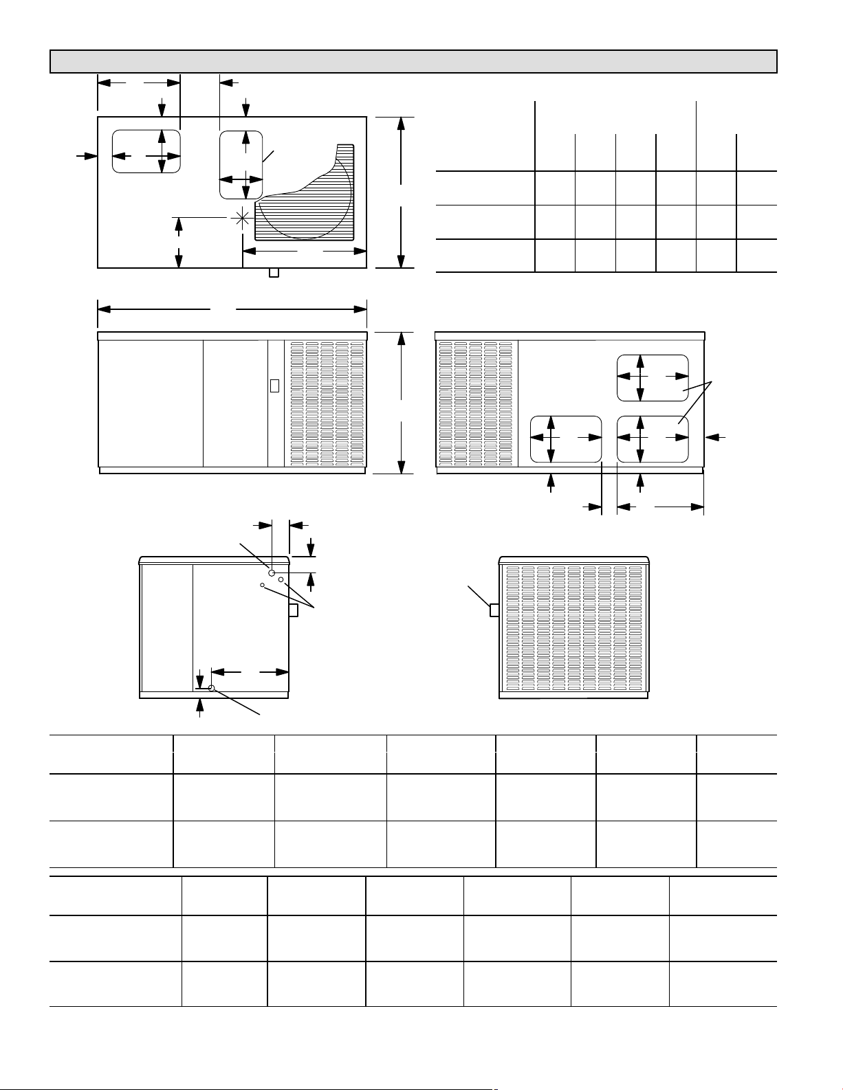
15GCSX Unit Dimensions − inches (mm)
FG
B
E
D
2−1/2 (64)
DOWNFLOW
SUPPLY AIR
OPENING
FF
AA
2−3/4
(70)
2−1/2 (64)
D
E
DOWNFLOW
RETURN AIR
OPENING
EE
TOP VIEW
BB
CCDD
Model
Number
15GCSXAV−24 74 94 125 97 15.5 28.5
C
15GCSXAV−30 74 94 125 97 15.5 28.5
15GCSXAV−36 84 101 126 105 16 29.5
15GCSXAV−42 108 136 176 140 20 33
15GCSX(A,B)V−48 112 137 177 144 20 33.5
15GCSX(A,B)V−60 117 143 184 151 20 33.5
Corner Weights
AA BB CC DD EE FF
lbs. lbs. lbs. lbs. in. in.
Center Of
Gravity
GAS PIPING INLET
2−1/2 (64)
Model No.
15GCSXAV−24
15GCSXAV−30
15GCSXAV−36
15GCSXAV−42
15GCSX(A,B)V−48
15GCSX(A,B)V−60
D
2 (51)
D
2−3/4
JK
E
E
(70)
HORIZONTAL
RETURN
AIR
OPENINGS (2)
H
FRONT VIEW
4−1/4 (108)
3−1/4 (83)
ELECTRICAL INLET
HORIZONTAL
SUPPLY AIR
A
OPENING
E
D
2−3/4
(70)
BACK VIEW
FLUE
OUTLET
L
CONDENSATE DRAIN
END VIEW
A B C D E F
in. mm in. mm in. mm in. mm in. mm in. mm
34−1/4 870 65−3/8 1661 36−1/2 927 11−1/4 286 17−1/4 438 20 508
38−1/4 972 75 1905 46 1168 11−1/4 286 19−1/4 489 22 559
END VIEW
Model No.
15GCSXAV−24
15GCSXAV−30
15GCSXAV−36
15GCSXAV−42
15GCSX(A,B)V−48
15GCSX(A,B)V−60
F G H J K L
in. mm in. mm in. mm in. mm in. mm in. mm
20 508 8−1/2 216 3 76 20−1/4 514 4−1/2 114 19 483
22 559 9−1/4 241 3−1/4 83 22−1/4 572 4 102 16−1/4 413
Page 2
Page 3
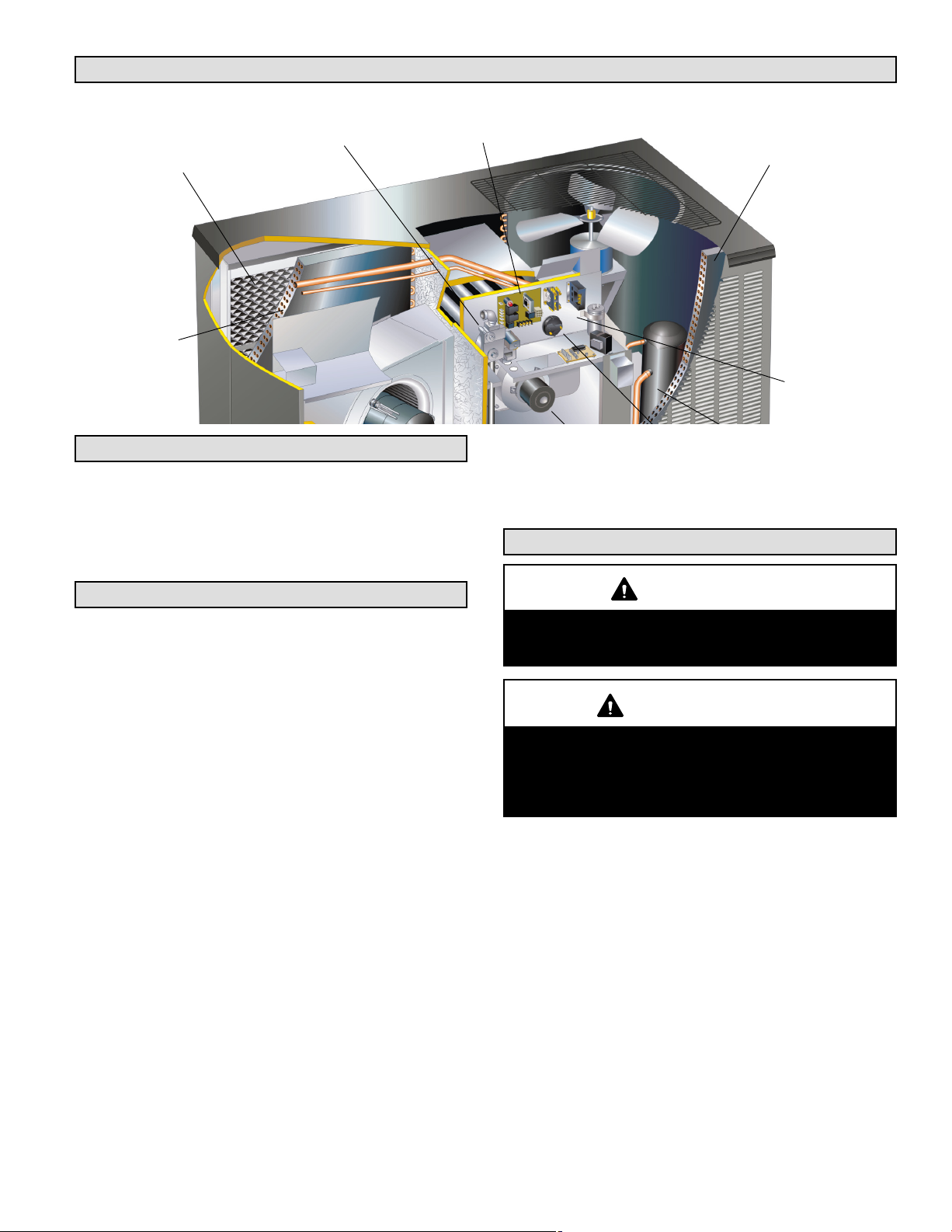
Parts Arrangement
Air Purification System
PureAir
(Optional)
Evaporator
Coil
®
Gas Valve
Ignition Control
Shipping & Packing List
1 − Assembled gas package unit
1 − Vent hood assembly with screen and screws
As soon as the unit is received, it should be inspected for
possible damage during transit. If you find any damage,
immediately contact the last carrier.
Board
tested. The units require electric power, gas piping,
condensate drain and duct connections at the point of
installation. In addition, the heating vent hood must be
installed before the unit is placed into operation
Condenser
Coil
Control Box
Safety Information
General
These installation instructions are intended as a general
guide only, for use by an experienced, qualified contractor.
The 15GCSX units are single−package air conditioners
with two−stage gas heat designed for outdoor installation
on a rooftop or a slab.
The unit must be sized based on heat loss and heat gain
calculations made according to the methods of the Air
Conditioning Contractors of America (ACCA).
The units are shipped assembled. All piping, refrigerant
charge, and electrical wiring are factory−installed and
CAUTION
As with any mechanical equipment, personal injury
can result from contact with sharp sheet metal
edges. Be careful when you handle this equipment.
IMPORTANT
This unit is charged with HFC−410A refrigerant. Operating pressures for units charged with HFC−410A
are higher than pressures in units charged with
HCFC−22. All service equipment MUST be rated for
use with HFC−410A refrigerant.
Page 3
Page 4
WARNING
Product contains fiberglass wool.
Disturbing the insulation in this product during
installation, maintenance, or repair will expose you
to fiberglass wool dust. Breathing this may cause
lung cancer. (Fiberglass wool is known to the State
of California to cause cancer.)
Fiberglass wool may also cause respiratory, skin,
and eye irritation.
To reduce exposure to this substance or for further
information, consult material safety data sheets
available from address shown below, or contact your
supervisor.
Lennox Industries Inc.
P.O. Box 799900
Dallas, TX 75379−9900
These units must be installed in accordance with all
applicable national and local safety codes.
These instructions are intended as a general guide and do
not supersede local codes in any way. Consult authorities
having jurisdiction before installation.
If components are to be added to a unit to meet local codes,
they are to be installed at the dealer’s and/or customer’s
expense.
These units are design listed by UL in both the United
States and Canada as follows:
D For use as a forced air furnace with cooling.
D For outdoor installation only.
D For installation on combustible material.
D For use with natural gas or L.P./propane gas only. Use of
L.P./propane gas requires installation of an L.P.
conversion kit, which must be ordered separately.
These units are not suitable for use with conventional
venting systems.
The following safety requirements must also be met when
the 15GCSX units are installed:
1 − Use only with the type of fuel approved for use with this
appliance. Refer to the unit rating plate.
2 − Position, locate and install the 15GCSX unit only as
outlined in these instructions.
3 − Provide adequate clearance around the vent hood as
specified in these instructions.
4 − Do not use an open flame to check for gas leaks. Use a
commercially available soap solution, which has been
designed specifically to check for gas leaks. Refer to
the Gas Supply and Piping section.
5 − Check the unit operation after start−up to make sure
that the 15GCSX is operating within the intended
temperature rise range. The duct system must be
designed to provide an external static pressure within
the allowable range. Refer to the unit rating plate.
Lennox does not recommend the use of 15GCSX units as a
construction heater during any phase of construction. Very
low return air temperatures, harmful vapors and operation
of the unit with clogged or misplaced filters will damage the
unit.
15GCSX units may be used for heating of buildings or
structures under construction, if the following conditions
are met:
D The vent hood must be installed per these installation
instructions.
D A room thermostat must control the furnace. The use of
fixed jumpers that will provide continuous heating is not
allowed.
D The return air duct must be provided and sealed to the
furnace.
D Return air temperature range between 60°F (16°C) and
80°F (27°C) must be maintained.
D Air filters must be installed in the system and must be
maintained during construction.
D Air filters must be replaced upon construction
completion.
D The input rate and temperature rise must be set per the
unit rating plate.
D One hundred percent (100%) outdoor air must be
provided for combustion air requirements during
construction. Installation of this unit in its intended
outdoor location will accomplish this.
D The heat exchanger, components, duct system, air
filters and evaporator coil must be thoroughly cleaned
following final construction clean−up.
D The unit operating conditions (including ignition, input
rate, temperature rise and venting) must be verified
according to these installation instructions.
NOTE − The Commonwealth of Massachusetts
stipulates these additional requirements:
D Gas furnaces shall be installed by a licensed
plumber or gas fitter only.
D The gas cock must be T handle" type.
D When flexible connectors are used, the maximum
length shall not exceed 36".
Location Selection
Use the following guidelines to select a suitable location for
these units.
1 − Unit is designed for outdoor installation only. Unit must
be installed so all electrical components are protected
from water.
2 − Condenser coils must have an unlimited supply of air.
3 − For ground level installation, use a level pre−fabricated
pad or use a level concrete slab with a minimum
thickness of 4 inches. The length and width should be
at least 6 inches greater than the unit base. Do not tie
the slab to the building foundation.
4 − Maintain level within a tolerance of 1/4 inch maximum
across the entire length or width of the unit.
Page 4
Page 5
5 − Do not locate the unit where the combustion air supply
will be exposed to any corrosive substance, including
the following:
Permanent wave solutions,
Chlorinated waxes or cleaners,
Chlorine−based swimming pool chemicals,
Water−softening chemicals,
De−icing salts or chemicals,
Carbon tetrachloride,
Halogen−type refrigerants,
Cleaning solvents (e.g., perchloroethylene),
Printing inks, paint removers, varnishes, etc.,
Cements and glues,
Anti−static fabric softeners used in clothes dryers,
Masonry acid−washing materials,
Chlorinated laundry products,
Hydrochloric acid.
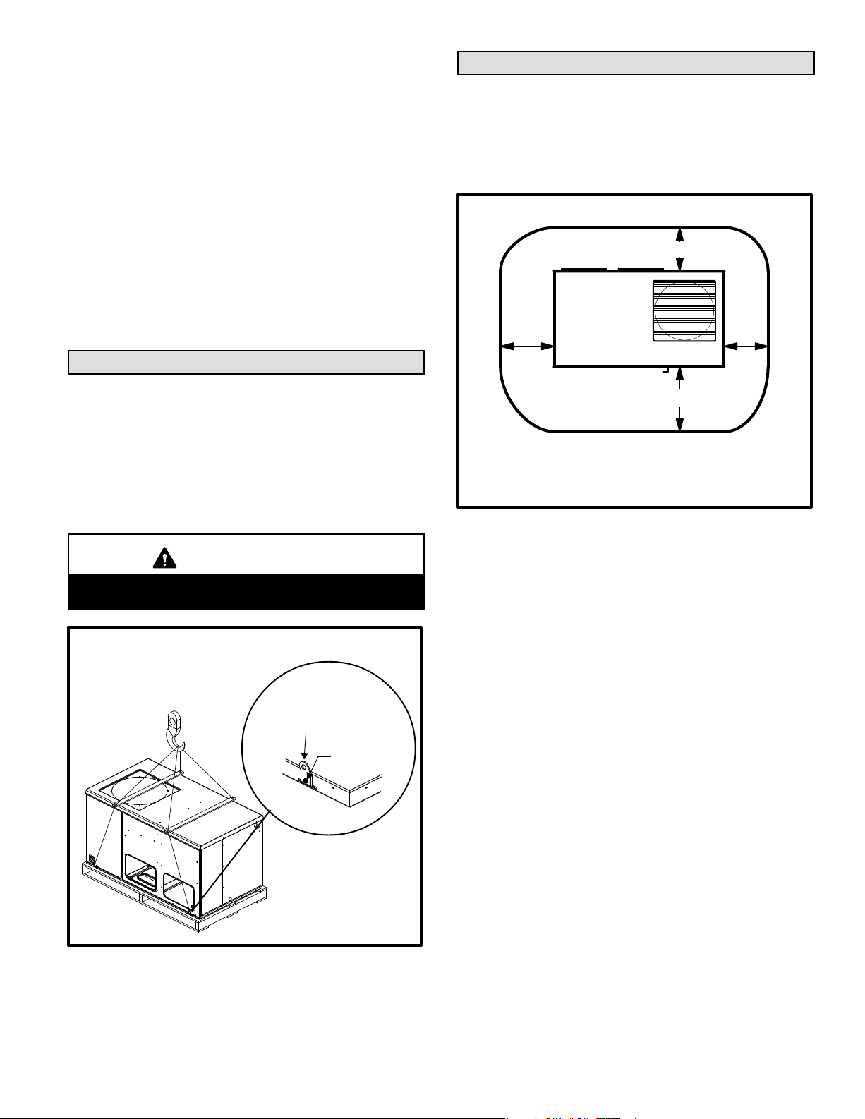
Rigging & Setting Unit
Exercise care when moving the unit. Do not remove any
packaging until the unit is near the place of installation. An
optional lifting lug kit (92M51) may be purchased
separately for use in rigging the unit for lifting. The
spreader lengths must exceed the width across the top
of the unit. Recommended spreader lengths: for use with
2, 2−1/2 and 3−ton units −− 44"; for use with 3−1/2, 4 and 5−ton
units −− 54".
CAUTION
Before lifting a unit, make sure that the weight is distributed equally on the cables so that it will lift evenly.
Accessory Lift Kit
Lifting Bracket
Sheet Metal
Screw
Figure 1
Units may also be moved or lifted with a forklift while still in
the factory supplied packaging.
NOTE − Length of forks must be a minimum of 42 inches.
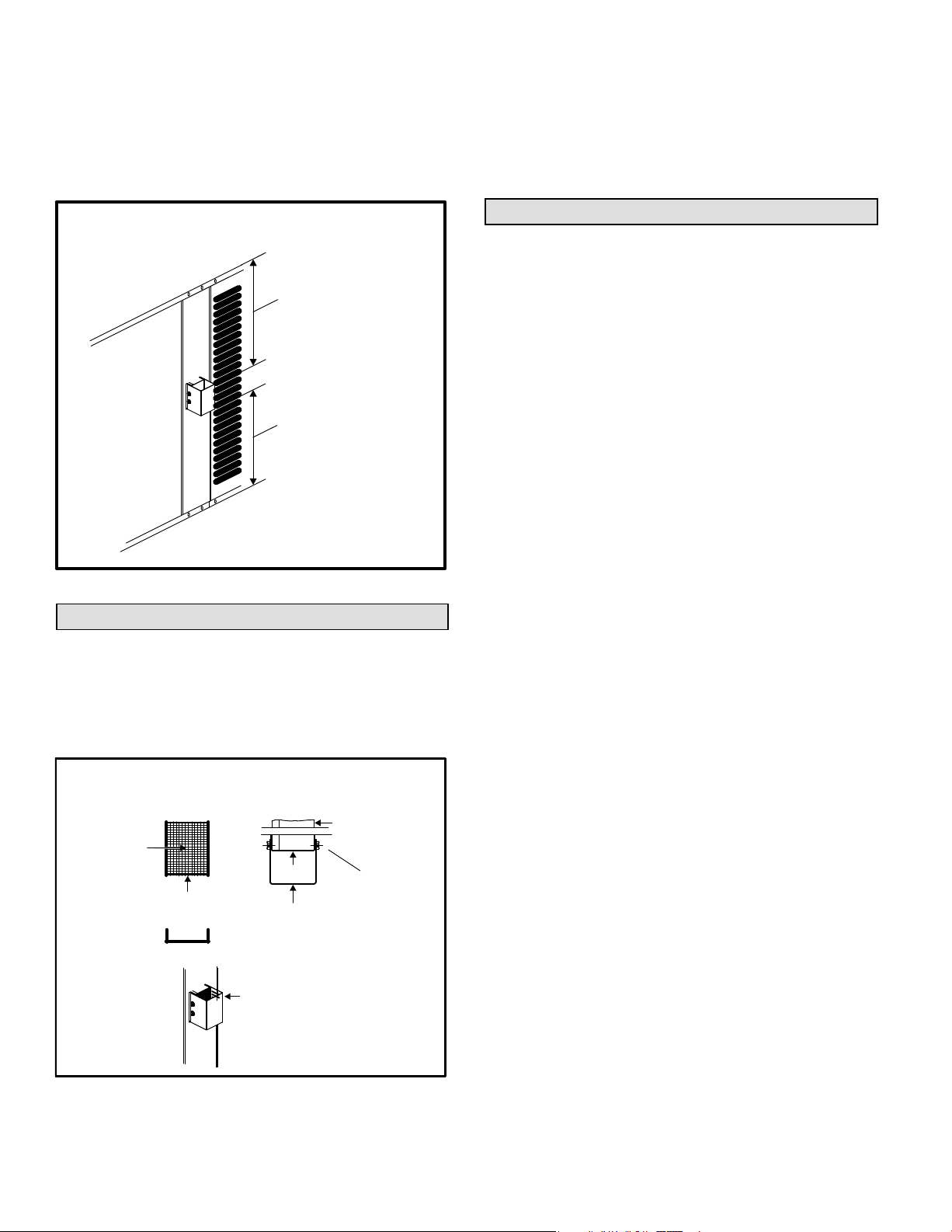
Clearances
All units require certain clearances for proper operation
and service. Refer to figure 2 for the clearances required
for combustible construction, servicing, and proper unit
operation.
NOTE − Do not permit overhanging structures or shrubs to
obstruct condenser air discharge outlet or vent outlet.
Service Clearances − Inches (Millimeters)
3 (76)
30
(762)
48 (1219)
NOTE − Top Clearance − 36 in. (914 mm)
NOTE − Entire perimeter of unit base requires
support when elevated above mounting surface.
Figure 2
In the U.S. units may be installed on combustible flooring
made from wood or class A, B, or C roof covering material.
In Canada, units may be installed on combustible flooring.
The products of combustion are discharged through a
screened vent outlet in the front mullion.
Install the unit so that the products of combustion will not
damage the outer building structure.
The vent outlet must be at least 4 feet below, 4 feet
horizontally from and 1 foot above any door, window or
gravity air inlet into the building. In addition, install the unit
so that the vent outlet is at least 3 feet above any forced air
inlet located within 10 feet.
Clearances to the vent outlet must also be consistent with
the requirements of the current National Fuel Gas Code
(Z223.1) and/or the standards of the current CSA B149
codes.
Figure 3 shows the minimum clearances to combustibles
required above and below the vent hood. The minimum
clearance in front of the vent hood is 24 inches.
Install the unit so that snow accumulation will not restrict
the flow of the flue products. Allow a required minimum
horizontal clearance of 4 feet from electric meters, gas
meters, regulators and relief equipment. In addition to the
above requirements, ensure that unwanted ice caused by
condensate is not allowed to accumulate around the unit.
Do not locate the unit on the side of the building where the
prevailing winter winds could trap moisture, causing it to
24
(610)
Page 5
Page 6
freeze on the walls or on overhangs (under eaves). The
vent outlet should not discharge flue products on a
sidewalk, patio or other walkway where the condensate
could cause the surface to become slippery.
Do not install the unit so that the products of
combustion will be allowed to accumulate within a
confined space and recirculate.
Minimum Clearances to Combustible Materials
Above and Below Vent Hood
Minimum Clearance
AboveVent Hood:
Distance fromTop
ofVent Hood
toTop of Unit
Minimum Clearance
BelowVent Hood:
Distance from Bottom
ofVent Hood to Base
of Unit
Figure 3
Vent Hood Installation
The vent hood, screen and screws are shipped inside the
unit in the plastic bag which contains the installation
instructions.
1 − Insert the vent screen into the vent tube Once
inserted, the screen should be flush with the end of the
tube as shown in figure 4.
Vent Hood Installation
FrontView
Screen
VentTube
Screen is pre−formed
Figure 4
TopView
Screen
Vent Hood
Slotted side of
vent hood faces
condenser coil.
VentTube
NOTE −
Screws
should pass
through
sides of
screen to
hold screen
in place.
2 − Position the vent hood over the vent tube so that the
slotted side of the hood faces the condenser coil. Use
the four sheet metal screws (provided) to secure the
vent hood to the vent tube. The screws should pass
through the sides of the screen in order to hold the
screen in place.
The vent hood must be installed prior to unit start−up.
Existing Common Vent Systems
If this packaged outdoor unit is replacing an existing
indoor furnace that is being removed from a venting
system commonly run with a water heater or other gas
appliance, the venting system is likely to be too large to
properly vent the remaining attached appliance(s).
Conduct the following test while the water heater is
operating and the other gas appliances (which are not
operating) remain connected to the common venting
system.
1 − Seal any unused openings in the common venting
system.
2 − Inspect the venting system for proper size and horizontal
pitch. Determine that there is no blockage, restriction,
leakage, corrosion, or other deficiencies which could
cause an unsafe condition.
3 − Close all building doors and windows and all doors
between the space in which the appliances remaining
connected to the common venting system are located
and other spaces of the building. Turn on clothes
dryers and any appliances not connected to the
common venting system. Turn on any exhaust fans,
such as range hoods and bathroom exhausts, so they
will operate at maximum speed. Do not operate a
summer exhaust fan. Close fireplace dampers.
4 − Follow the lighting instructions. Turn on the appliance
that is being inspected. Adjust the thermostat so that
the appliance operates continuously.
5 − After the burner has operated for 5 minutes, test for
leaks of flue gases at the draft hood relief opening. Use
the flame of a match or candle, or smoke from a
cigarette, cigar, or pipe.
6 − After determining that each appliance connected to the
common venting system is venting properly, (step 3)
return all doors, windows, exhaust fans, fireplace
dampers, and any other gas−burning appliances to
their previous mode of operation.
7 − If a venting problem is found during any of the
preceding tests, the common venting system must be
modified to correct the problem.
If necessary, you must resize the common venting
system to the minimum vent pipe size determined by
using the appropriate tables in Appendix G. (These are
in the current standards of the National Fuel Gas Code
ANSI-Z223.1/NFPA 54 in the USA, and the
Page 6
Page 7

appropriate Category 1 Natural Gas and Propane
appliances venting sizing tables in the current
standards of the CSA B149 Natural Gas and Propane
Installation Codes in Canada.)
Page 7
Page 8
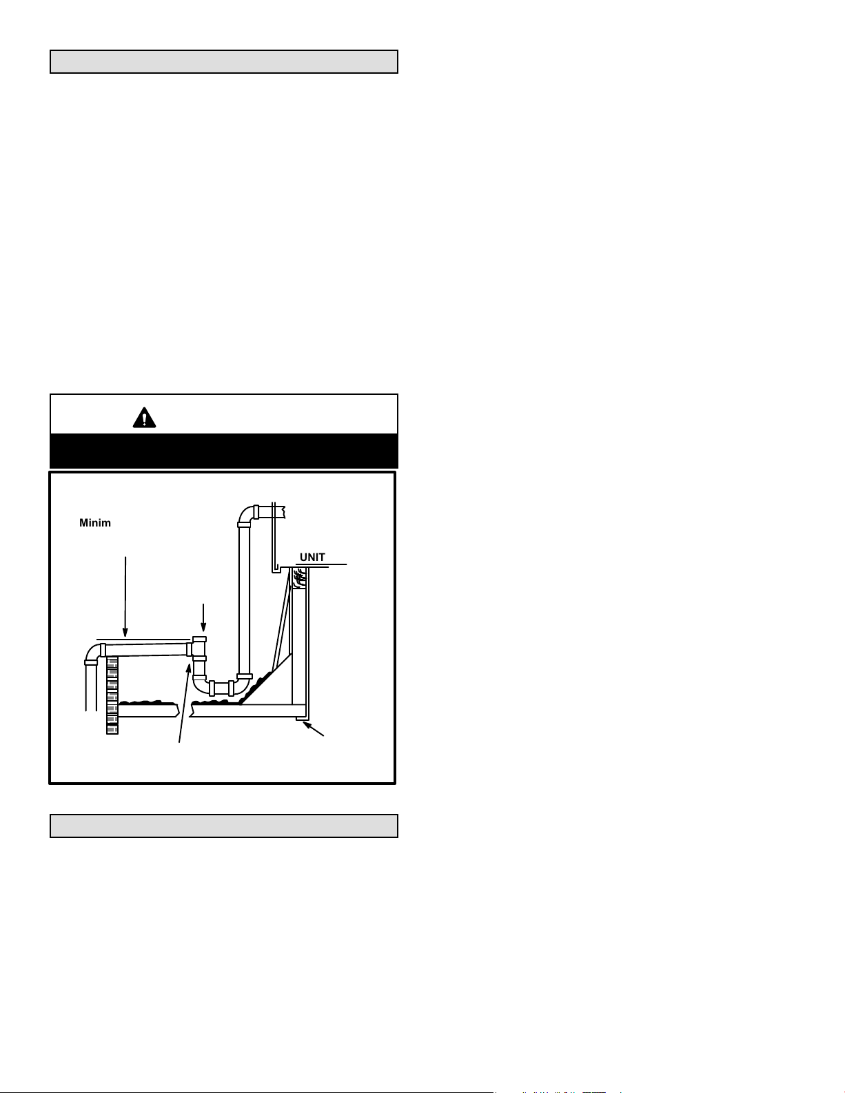
Condensate Drain
The 15GCSX unit is equipped with a 3/4 inch FPT coupling
for condensate line connection. Plumbing must conform to
local codes. Use a sealing compound on male pipe
threads.
The drain line must be properly trapped and routed to a
suitable drain. See figure 5 for proper drain arrangement.
The drain line must pitch to an open drain or pump a
minimum of 1 inch per 10 feet to prevent clogging of the
line. The drain line must be supported so that weight of
drain line is not carried by drain line connection. Seal
around drain connection with suitable material to prevent
air leakage into return air system.
Drain piping should not be smaller than drain connection
at coil. An open vent in drain line will some times be
required due to line length, friction and static pressure.
Drains should be constructed in a manner to facilitate
future cleaning.
NOTE − The condensate drain line MUST be trapped to
provide proper drainage.
CAUTION
Condensate line connection must be hand−tightened. Do not use tools.
Filters must always be installed ahead of evaporator coil
and must be kept clean or replaced. Dirty filters will reduce
the airflow of the unit. Filter sizes are shown in table 1.
Typical Condensate Drain
Minimum Pitch
1 in. (25 mm) per
10’ (3 m) of line
OPEN
VENT
Trap must be deep enough to offset maximum
static difference (Generally, 3 inches minimum).
UNIT
MOUNTING
FRAME
Figure 5
Filters
Filters are not factory−supplied with the unit; however,
optional internally installed filter kits are available. Filter kit
92M54 is used with 2, 2−1/2 and 3−ton units. Filter kit 92M55
is used with 3−1/2, 4 and 5−ton units. The filter kits
accommodate the use of 1", 2" or 4" filters. If the optional
filter kit is not used, a filter must be field−installed.
Page 8
Page 9

Table 1
Unit Filter Size
Unit Model Filter Size Filter Quantity
−24, −30, −36 20 in. X 25 in. 1
−42, −48, −60 16 in. X 25 in. 2
The Healthy Climate® PureAir® air purification system
(PCO20−28) may be used with 15GCSX units installed in
horizontal air discharge applications only. Installation
hardware kit (Y0629) is required to install the PCO20−28
(X8787) in the packaged unit. The PCO20−28 is designed
for universal voltage, and is ready to operate at 208/230V.
When used, the PCO should be installed before the unit is
set in place and before the duct connections are made.
Supply & Return Duct Connections
The duct system should be designed and sized according
to the methods in Manual Q of the Air Conditioning
Contractors of America (ACCA).
A closed return duct system shall be used. This shall not
preclude use of economizers or outdoor fresh air intake. It
is recommended that supply and return duct connections
at the unit be made with flexible joints.
The supply and return air duct systems should be
designed for the CFM and static requirements of the job.
They should NOT be sized by simply matching the
dimensions of the duct connections on the unit.
CAUTION
When fastening duct system to side duct flanges on
unit, insert screws through duct flanges only. Do not
insert screws through casing. Outdoor duct must be
insulated and waterproofed.
The 15GCSX unit is shipped ready for horizontal air
discharge (side duct connections). If bottom air discharge
is desired, the covers must be removed from the supply
and return air openings on the bottom of the unit and
re−installed to cover the side openings.
The upper return air opening cover must be removed when
the PureAir
used. In PCO applications, both upper and lower return air
openings must be covered by the return air plenum to
ensure proper PCO operation. The upper return air
opening is not required in horizontal applications when
the PCO is not used.
1.Remove screw and lift.
2.Slide cover to free back pin.
®
air purification system (PCO20−28) is being
Removing Supply and Return
Air Opening Covers
2
1
Base
Figure 6
Page 9
Page 10

Compressors
Units are shipped with the compressor mountings
factory−adjusted and ready for operation.
CAUTION
Do not loosen compressor mounting bolts.
Gas Supply and Piping
Check the unit rating plate to confirm whether unit is
equipped for use with natural gas or LP/propane. If
conversion is required use the approved conversion kit.
NOTE − Units are shipped equipped for natural gas, but can
be converted to LP/propane with a conversion kit.
Conversion must be performed by an approved
licensed pipe fitter or technician.
All LP/propane gas equipment must conform to the safety
standards of the National Fire Protection Association.
Complete information regarding tank sizing for
vaporization, recommended regulator settings, and pipe
sizing is available from most regulator manufacturers and
LP/propane gas suppliers.
Proper sizing of gas piping depends on the cubic feet per
hour of gas flow required, specific gravity of the gas and
length of run. In the United States, the current National Fuel
Gas Code Z223.1 should be followed in all cases unless
superseded by local codes or gas company requirements.
Refer to tables 2 and 3. In Canada, refer to the current CSA
B.149 installation codes.
Table 2
Gas Heat Application Data
Unit
Heating Size
68 67,500 54,000 63
83 82,500 66,000 77
90 90,000 72,000 84
110 110,000 88,000 102
138 137,500 110,000 128
*Based on 1075 Btu per cubic foot of natural gas.
Before connecting piping, check with gas company or
authorities having jurisdiction for local codes or
requirements. When installing gas supply piping, length
of run from gas meter must be considered in
determining pipe size for 0.5 inch w.c. maximum
pressure drop. Do not use supply pipe smaller than unit
Input Rating
(Btu)
Output Rating
(Btu)
Gas Capacity*
(FT3 / HR)
gas connection. For natural gas unit, supply pressure at
the unit gas connection must be a minimum of 5 inches
w.c. and a maximum of 10.5 w.c. For LP/propane gas
units, supply pressure at the unit gas connection must
be a minimum of 11 inches w.c. and a maximum of 13.0
inches w.c.
Table 3
Gas Pipe Capacity−FT3 / HR
Length in Feet
10 132 278 520 1050
20 92 190 350 730
30 73 152 285 590
40 63 130 245 500
50 56 115 215 440
60 50 105 195 400
70 46 96 180 370
80 43 90 170 350
90 40 84 160 320
100 38 79 150 305
The gas supply piping should be routed through the
grommet on the side of the unit. Refer to figure 7.
Nominal Iron Pipe Size (inches)
1/2 in. 3/4 in. 1 in. 1−1/4 in.
Gas Piping and Electrical Conduit Access
Gas Line Entry
Thermostat
Entry
Line Voltage
Entry
Figure 7
When making piping connections, a drip leg should be
installed on vertical runs to serve as a trap for sediment or
condensate. A 1/8 inch N.P.T. tap accessible for test gauge
connection must be provided in field piping upstream from
gas supply connection to unit. Install a ground joint union
between gas control manifold and the manual main
shut−off valve. See figure 8.
Compounds used on threaded joints of gas piping shall be
resistant to the action of propane/LP gases.
Page 10
Page 11

Drip Leg Installation
field provided
1/8 in. pressure tap
ground joint
union
manual main
shut−off valve
gas piping
support
unit
drip
leg
Figure 8
Pressure Test Gas Piping
When pressure testing gas lines, the gas valve must be
disconnected and isolated. Gas valve can be damaged if
subjected to more than 0.5 psig (14 inch w.c.). See figure 9.
If test pressure is equal to or less than 0.5 psig (14 inch
w.c.) shutoff the manual main shut-off valve before
pressure testing to isolate unit from gas supply system.
Isolate Gas Valve To Pressure Test
Manual Main Shut−off Valve Will Not Hold Test
Pressures in Excess of 0.5 PSIG (14 in. w.c.)
NOTE − There may be a local gas utility requirement
specifying a minimum diameter for gas piping. All units
require a 1/2 inch pipe connection at the gas valve.
Gas piping recommendations:
CAUTION
If a flexible gas connector is required or allowed by
the authority that has jurisdiction, black iron pipe
shall be installed at the gas valve and must extend
outside the cabinet. The flexible connector can then
be added between the black iron pipe and the gas
supply line.
1 − A drip leg and a ground joint union must be installed in
the gas piping.
A ground joint union is recommended by the
manifold/valve.
2 − When required by local codes, a manual shut-off valve
may have to be installed outside of the unit.
3 − Use pipe thread sealing compound resistant to
propane gas sparingly on male threads.
4 − The gas supply should be a separate line and installed
in accordance with all safety codes. After the gas
connections have been completed, open the main
shut-off valve admitting normal gas pressure to the
mains. Check all joints for leaks with soap solution or
other material suitable for the purpose.
unit
gas valve
cap
Figure 9
NOTE − Codes may require that manual main shut off valve
and union (furnished by installer) be installed in gas line
external to unit. Union must be of the ground joint type.
!
WARNING
Danger of explosion. Can cause injury or
product or property damage. Do not use
matches, candles, flame or other sources
of ignition to check for leaks.
After gas piping is complete, carefully check all piping
connections (factory and field) for gas leaks. Use soap
solution or other preferred means.
NOTE − In case of emergency shutdown, shut off main
manual gas valve and disconnect main power to unit.
These devices should be properly labeled by installer.
The heating value of the gas may differ with locality. The
value should be checked with the local gas utility.
CAUTION
Some soaps used for leak detection are corrosive to
certain metals. Carefully rinse piping thoroughly after leak test has been completed. Do not use
matches, candles, flame or other sources of ignition
to check for gas leaks.
5 − The unit and its individual manual shut-off valve must
be disconnected from the gas supply piping system
during any pressure testing of that system at test
pressures in excess of 1/2 PSIG (3.48kPa).
IMPORTANT
The unit must be isolated from the gas supply piping
system by closing its individual manual shut−off
valve during any pressure testing of the gas supply
piping system at test pressures equal to or less than
1/2 psig. See figure 9.
The unit and its individual shut−off valve must be disconnected from the gas supply piping system during
any pressure testing of the system at test pressures
greater than 1/2 psig.
6 − A 1/8 inch N.P.T. plugged tapping, accessible for test
gage connections, must be installed immediately
upstream of the gas supply connection to the furnace.
Page 11
Page 12

Electrical
All wiring should be done in accordance with the
current National Electric Code ANSI/NFPA No. 70 in the
United States. In Canada, wiring must be done in
accordance with the current CSA C22.2 Part 1. Local
codes may take precedence.
Use wiring with a temperature limitation of 75_C min.; run
the 208 or 230 volt, 60 hertz electric power supply through a
fused disconnect switch to control box of unit and connect
as shown in the wiring diagram located on the inside of the
control access panel.
Unit must be electrically grounded in accordance with local
codes or in the absence of local codes with the National
Electric Code, ANSI/NFPA No. 70 (latest edition) or CSA
C22.2 Part 1 (latest edition).
Power supply to the unit must be N.E.C. Class 1, and must
comply with all applicable codes. A fused disconnect
switch should be field provided for the unit. The switch must
be separate from all other circuits. If any of the wire
supplied with the unit must be replaced, replacement wire
must be of the type shown on the wiring diagram.
Electrical wiring must be sized to carry minimum circuit
ampacity marked on the unit. USE COPPER
CONDUCTORS ONLY. Each unit must be wired with a
separate branch circuit and be properly fused.
CAUTION
When connecting electrical power and control wiring to the unit, waterproof type connectors MUST be
used so that water or moisture cannot be drawn into
the unit during normal operation.
See figure 10 for field connection of line voltage wiring. See
figure 11 for typical wiring diagram.
208/230 Line Voltage Wiring
contactor
fused disconnect switch
(furnished by installer)
L1
ground
lug
NOTE − If 208 voltage is supplied, transformer
connections must be made.
L2
Figure 10
Thermostat
The room thermostat should be located on an inside wall
where it will not be subject to drafts, sun exposure or heat
from electrical fixtures or appliances. Follow
manufacturer’s instructions enclosed with thermostat for
general installation procedure. Color coded insulated wires
(# 18 AWG) should be used to connect thermostat to unit.
Four wires are required for cooling.
Heat Anticipator Setting
It is important that the anticipator setpoint be correct. Too
high of a setting will result in longer heat cycles and a
greater temperature swing in the conditioned space.
Reducing the value below the correct setpoint will give
shorter ON" cycles and may result in the lowering of the
temperature within the conditioned space.
Heat Anticipator Setting: 0.70 AMP
Page 12
Page 13

Typical Wiring Diagram
15GCSX Series Gas Packaged Units
Page 13
Page 14

Blower Control (A54)
BLOWER CONTROL (A54)
16−PIN PLUG
(BOARD TO MOTOR)
ADJUST
SELECTOR PINS
(Setting affects both
heating and cooling
modes)
DIAGNOSTIC
LED
Figure 12
!
WARNING
Electric shock hazard. Can cause injury or
death. Before attempting to perform any
service or maintenance, turn the electrical
power to unit OFF at disconnect switch(es).
Unit may have multiple power supplies.
15GCSX units are equipped with a variable speed motor
that is capable of maintaining a specified CFM throughout
the external static range. A particular CFM can be obtained
by positioning jumpers (COOL, HEAT, and ADJUST) on
the blower control. The HEAT and COOL jumpers are
labeled A, B, C and D. Each of the numbers corresponds
with an air volume (CFM) setting. The ADJUST jumper is
labeled Test, −, +, and Norm. The + and − pin settings are
used to add or subtract a percentage of the CFM selected.
The Test jumper is used to operate the motor in the test
mode. See figure 12.
Factory settings for the blower speed jumpers are given in
the wiring diagram in figure 11. Figure 12 shows the blower
control. Use tables 4, 5 and 6 to determine the correct air
volume for operation in heat and cool mode.
The CFM LED located on the blower control flashes one
time per 100 cfm to indicate selected blower speed. For
example, if the unit is operating at 1000 CFM, CFM LED will
flash 10 times. If the CFM is 1150, CFM LED will flash 11 full
times plus one fast or half flash.
At times the light may appear to flicker or glow. This takes
place when the control is communicating with the motor
between cycles. This is normal operation.
Read through the jumper settings section before adjusting
the jumper to obtain the appropriate blower speed.
HEATING SPEED
SELECTOR PINS
COOLING SPEED
SELECTOR PINS
To change jumper positions, gently pull the jumper off the pins
and place it on the desired set of pins. The following section
outlines the different jumper selections available and
conditions associated with each one. Refer to figure 12.
After the CFM for each application has been determined,
the jumper settings must be adjusted to reflect those given
in tables 4, 5 and 6. From the tables, determine which row
most closely matches the desired CFM. Once a specific
row has been chosen (+, NORMAL, or −), CFM volumes
from other rows cannot be used. Below are descriptions of
the jumper selections.
The variable speed motor slowly ramps up to and down
from the selected air flow during both cooling and heating
demand. This minimizes noise and eliminates the initial
blast of air when the blower is initially energized.
ADJUST
The ADJUST pins allow the motor to run at normal speed,
approximately 15 percent higher, or approximately 15
percent lower than normal speed. Tables 4, 5 and 6 give
three rows (+, NORMAL, and −) with their respective CFM
volumes. Notice that the normal adjustment setting for heat
speed position C in table 4 is 900 CFM. The + adjustment
setting for that position is 1035 CFM and for the −
adjustment setting is 765 CFM. After the adjustment
setting has been determined, choose the remaining speed
settings from those offered in the table in that row.
The TEST pin is available to bypass the blower control and
run the motor at approximately 70 percent to make sure
that the motor is operational. This is used mainly in
troubleshooting. The G terminal must be energized for the
motor to run.
Page 14
Page 15

COOL
The COOL jumper is used to determine the CFM during
cooling operation. This jumper selection is activated for
cooling when Y1 is energized.
The blower motor runs at 80 percent of the selected air
flow for the first 7−1/2 minutes of each cooling demand.
This feature allows for greater humidity removal and
saves energy.
In the cooling mode, the blower control delays blower
operation for 5 seconds after the compressor starts. The
blower continues to operate for 90 seconds after the
compressor is de−energized.
HEAT
blower continues to operate for 90 seconds after the gas
valve is de−energized.
CONTINUOUS FAN
When the thermostat is set for Continuous Fan" operation
and there is no demand for heating or cooling, the blower
control will provide 50 percent of the COOL CFM selected.
NOTE − With the proper thermostat and subbase,
continuous blower operation is possible by closing the R to
G circuit. Cooling blower delay is also functional in this
mode.
DEHUMIDIFICATION
The blower control includes an HUM terminal which
provides for connection of a humidistat. The JV1 resistor on
the blower control must be cut to activate the HUM
The HEAT jumper is used to determine CFM during gas
heat operation only. These jumper selections are activated
only when W1 is energized.
In the heating mode, the blower control delays blower
operation for 30 seconds after the flame is established. The
terminal. The humidistat must be wired to open on humidity
rise. When the dehumidification circuit is used, the variable
speed motor will reduce the selected air flow rate by 25
percent when humidity levels are high. An LED (D1) lights
when the blower is operating in the dehumidification mode.
Table 4
15GCSXAV−24, 15GCSXAV−30 Blower Performance
0 through 0.80 in. w.g. (0 through 200 Pa) External Static Pressure Range
Jumper Speed Positions
ADJUST
Jumper
Setting
NORM 1000 470 800 380 600 285 900 425 1100 520 1000 470 900 425 800 380 500 235 400 190 300 140 450 210
A B C D A B C D A B C D
cfm L/s cfm L/s cfm L/s cfm L/s cfm L/s cfm L/s cfm L/s cfm L/s cfm L/s cfm L/s cfm L/s cfm L/s
+ 1150 545 920 435 690 325 1035 490 1265 595 1150 545 1035 490 920 435 575 270 460 215 345 165 520 245
COOL" Speed HEAT" Speed CONTINUOUS FAN" Speed
− 850 400 680 320 510 240 765 360 935 440 850 400 765 360 680 320 425 200 340 160 300 140 385 180
Table 5
15GCSXAV−36 Blower Performance
0 through 0.80 in. w.g. (0 through 200 Pa) External Static Pressure Range
Jumper Speed Positions
ADJUST
Jumper
Setting
NORM 1200 565 1000 470 800 380 1100 520 1350 635 1100 520 1000 470 900 425 600 285 500 235 400 190 550 260
A B C D A B C D A B C D
cfm L/s cfm L/s cfm L/s cfm L/s cfm L/s cfm L/s cfm L/s cfm L/s cfm L/s cfm L/s cfm L/s cfm L/s
+ 1380 650 1150 545 920 435 1265 575 1555 735 1265 595 1150 545 1035 490 690 325 575 270 460 215 635 300
− 1020 480 850 400 680 320 935 440 1150 540 935 440 850 400 765 360 510 240 425 200 350 165 470 220
COOL" Speed HEAT" Speed CONTINUOUS FAN" Speed
Table 6
15GCSXAV−42, 15GCSX(A,B)V−48, 15GCSX(A,B)V−60, Blower Performance
0 through 0.80 in. w.g. (0 through 200 Pa) External Static Pressure Range
Jumper Speed Positions
ADJUST"
Jumper
Setting
NORM 1800 850 1600 755 1400 660 1200 565 1750 825 1650 780 1350 635 1150 545 900 425 800 380 700 330 600 285
A B C D A B C D A B C D
cfm L/s cfm L/s cfm L/s cfm L/s cfm L/s cfm L/s cfm L/s cfm L/s cfm L/s cfm L/s cfm L/s cfm L/s
+ 2070 975 1840 870 1610 760 1380 650 2015 950 1900 895 1555 735 1325 625 1035 490 920 435 805 380 690 325
− 1530 720 1360 640 1190 560 1020 480 1490 700 1405 660 1150 540 980 460 765 360 680 320 595 280 510 240
COOL" Speed HEAT" Speed CONTINUOUS FAN" Speed
Page 15
Page 16

Cooling Start−Up
The cooling section is a complete factory package utilizing
an air−cooled condenser. The system is factory−charged
with HFC−410A refrigerant. The compressor is
hermetically sealed, internally sprung and base−mounted
with rubber−insolated hold−down bolts.
Pre−Start Check List:
1 − Make sure refrigerant lines do not rub against the
cabinet or each other.
2 − Inspect all electrical wiring, both factory− and
field−installed, for loose connections.
3 − Check voltage at the disconnect switch. Voltage must
be within the range listed on the unit nameplate. If not,
consult power company and have voltage condition
corrected before starting unit.
4 − Recheck voltage with unit running. If power is not
within the range listed on the unit nameplate, stop the
unit and consult the power company. Check unit
amperage. Refer to unit nameplate for correct running
amps.
5 − Make sure filter is in place before unit start−up.
Cooling Sequence of Operation
When the thermostat calls for cooling, R" is closed to G"
and Y" (figure 11). This completes the low voltage control
circuit, energizing the compressor, condenser fan motor
and blower motor.
NOTE − At the start of the each cooling demand, the
combustion air blower (draft motor) will operate for 10
seconds.
Unit compressors have internal protection. If there is an
abnormal rise in the compressor temperature, the
protector will open and the compressor will stop.
Blower Delay − Cooling
In the cooling mode, the circulating air blower operation is
delayed for 5 seconds after the compressor starts. The
blower continues to operate for 90 seconds after the
compressor is de−energized.
NOTE − With the proper thermostat and subbase,
continuous blower operation is possible by closing the R to
G circuit. Cooling blower delay is also functional in this
mode.
System Performance
This self−contained system has been factory−charged for
optimal performance. If performance is questionable, use
the following procedure to check the system.
Ensure that unit has been installed per these instructions
and that line voltage and air flow are both correct. Check
subcooling values by measuring pressure at the liquid line
(high side) service port. Measure liquid line temperature
within 2 inches of the service port connection to its main
tube. If subcooling measured deviates from values in table
7 by more than 2 degrees F, check internal seals, service
panels and duct system for air leaks, as well as restrictions.
Also check blower speed settings. Make all necessary
adjustments. If unit performance remains questionable,
recover unit refrigerant charge, evacuate to 500 Microns,
and weigh in refrigerant to match value given on unit
nameplate. It is critical that exact required charge is used.
Failure to follow this instruction will compromise system
performance. If unit performance is still questionable,
check for blocked coil or circuits, malfunctioning metering
devices or other system component problems.
Table 7
Liquid Subcooling Values
Liquid Line Subcooling
Unit Model No.
15GCSX−24 12_
15GCSX−30 12_
15GCSX−36 15_
15GCSX−42 10_
15GCSX−48 7_
15GCSX−60 8_
Verify system performance using table 8 as a general guide.
Table 8 should not be used for charging unit. Minor
variations in these pressures may be expected due to
differences in installations. Significant differences could
mean that the system is not properly charged or that a
problem exists with some component in the system.
Used carefully, this table could serve as a useful service
guide. Data is based on 80F dry bulb / 67F wet bulb return
air. Allow unit operation to stabilize before taking pressure
readings.
+/− 2 Deg. F @ ARI
82_F OD minus 80_F IDDB
/ 67_F IDWB
Page 16
Page 17

Table 8
Normal Operating Pressures
80F db / 67F wb RETURN AIR Air Temperature Entering Outdoor Coil (F)
UNIT PRESSURE 65 70 75 80 82 85 90 95 100 105 11 0 11 5
15GCSX−24
15GCSX−30 134 136 138 140 141 142 144 146 148 149 151 152
15GCSX−36 143 144 146 147 148 149 151 152 155 155 157 157
15GCSX−42 140 140 140 141 141 141 142 142 143 144 145 147
15GCSX−48 133 134 136 137 138 139 139 140 141 142 144 145
15GCSX−60 134 136 138 140 141 142 144 145 147 148 150 151
15GCSX−24
15GCSX−30 232 255 277 300 309 323 345 368 390 408 440 470
15GCSX−36 244 268 292 316 326 340 363 369 410 429 461 493
15GCSX−42 225 247 269 291 300 314 337 357 383 402 434 457
15GCSX−48 236 256 277 297 305 320 344 370 393 412 449 480
15GCSX−60 246 269 291 314 323 337 360 385 407 424 457 484
Suction
Liquid
142 143 144 146 146 147 148 149 150 151 152 153
219 242 264 287 296 310 333 355 379 398 430 457
Heating Start−Up
!
WARNING
Pre−Start Check List:
1 − Check the type of gas being supplied. Be sure it is the
same as listed on the unit nameplate.
2 − Make sure the vent hood has been properly installed.
FOR YOUR SAFETY READ BEFORE LIGHTING
BEFORE LIGHTING smell all around the appliance area
for gas. Be sure to smell around the base of the unit
because some gas is heavier than air and will settle down
low.
!
WARNING
Electric shock hazard. Can cause injury
or death. Do not use this unit if any part
has been under water. Immediately call a
qualified service technician to inspect
the unit and to replace any part of the control system and any gas control which
has been under water.
Use only your hand to turn the gas valve knob. Never use
tools. If the knob will not move by hand, do not try to repair
the gas valve. Call a qualified service technician. Force or
attempted repair may result in a fire or explosion.
This furnace is equipped with a direct ignition control. Do
not attempt to manually light the burners.
1 − Turn off electrical power to unit.
2 − Set thermostat to lowest setting.
3 − Turn the gas valve knob to the ON position. Refer to
figure 13.
4 − Turn on electrical power to unit.
5 − Set room thermostat to desired temperature. (If
thermostat setpoint temperature is above room
temperature after the pre−purge time expires, main
burners will light).
Electric shock hazard. Can cause injury or
death. Before attempting to perform any
service or maintenance, turn the electrical
power to unit OFF at disconnect switch(es).
Unit may have multiple power supplies.
!
WARNING
Danger of explosion and fire. Can cause
injury or product or property damage. You
must follow these instructions exactly.
!
WARNING
Danger of explosion. Can cause injury or
product or property damage. If overheating
occurs or if gas supply fails to shut off, shut
off the manual gas valve to the appliance
before shutting off electrical supply.
Page 17
Honeywell VR8205 Series Gas Valve
HIGH FIRE
ADJUSTING SCREW
(under cap)
LOW FIRE
ADJUSTING SCREW
(under cap)
INLET PRESSURE TAP
GAS VALVE SHOWN IN OFF POSITION
Figure 13
OUTLET
(MANIFOLD)
PRESSURE
TAP
Page 18

To Shut Down:
1 − Turn off electric power to unit.
2 − Turn the gas valve knob to the OFF position.
Post Start−up Check List (Gas)
After the control circuit has been energized and the heating
section is operating, make the following checks:
1 − Use soap solution to check for gas leaks in the unit
piping as well as the supply piping.
2 − Check for correct manifold gas pressures. See
Manifold Gas Pressure Adjustment."
3 − Check the supply gas pressure. It must be within the
limits shown on rating nameplate. Supply pressure
should be checked with all gas appliances in the
building at full fire. At no time should the supply gas
pressure exceed 10.5 inches w.c., nor drop below 5.0
inches w.c. for natural gas units. For propane gas,
supply gas pressure should not drop below 11 inches
w.c. If gas pressure is outside these limits, contact
your gas supplier for corrective action.
4 − Adjust temperature rise to the range specified on the
rating plate.
Checking and Adjusting Gas Input
NOTE − Units must be converted for use with LP/propane
gas. Conversion kit is ordered separately. Conversion
must be performed by an approved licensed pipe fitter
or technician.
The minimum permissible gas supply pressure is 5.0
inches W.C. for natural gas or 11.0 inches W.C. for
LP/propane gas. The maximum inlet gas supply pressure
is 10.5 inches W.C. for natural gas and 13.0 inches W.C. for
LP/propane gas. Gas input must never exceed the input
capacity shown on the rating plate.
Units fueled by natural gas are rated for manifold pressures
of 2.0 inches W.C. for first stage and 3.5 inches W.C. for
second stage.
Units fueled by LP/propane gas are rated for manifold
pressures of 5.6 inches W.C. for first stage and 10.0 inches
W.C. for second stage.
Measure manifold pressure: Shut off gas supply to the
unit. Remove plug from pressure tap. See figure 13.
Connect manometer or gauge to the proper pressure tap,
then turn on the gas supply.
The Honeywell VR8205 gas valve has separate adjusting
screws for first stage (LO) and second stage (HI). The
adjusting screws are positioned on either side of the
barbed fitting. Turn the adjusting screws clockwise to
increase pressure and input; turn counterclockwise to
decrease pressure and input. The pressure regulator
adjustment is sensitive. One turn of the adjusting screw
results in a large change in manifold pressure.
Final first−stage and second−stage manifold pressures
must be within the allowable rangers for the gas being
used.
For Natural Gas: Check the furnace rate by observing gas
meter, making sure all other gas appliances are turned off.
The test hand on the meter should be timed for at least one
revolution. Note the number of seconds for one revolution.
BTU/HR = Cubic Feet Per Revolution X 3600 X Heating Value
INPUT No. Seconds Per Revolution
The heating value of your gas can be obtained from your
local utility.
For LP/Propane Gas: If a gas meter is available, check the
input rate as described in the section above. Heating value
of propane gas is available from propane supplier.
Otherwise, the only check for the output rate is to properly
adjust the manifold pressure using a manometer. Typical
manifold setpoint for installations at altitudes from 0 to 4500
feet above sea level is 10.0 inches W.C.
High Altitude Information
Ratings shown on the rating plate for elevations up to 4,500
feet. For elevations above 4,500 feet, ratings should be
reduced at a rate of four percent for each 1,000 feet above
sea level. See National Fuel Gas Code Z223.1 (latest
edition) or the requirements of the CSA B149 installation
codes.
Heating Sequence of Operation
When the thermostat calls for heating, W1 is energized.
NOTE − The ignition control ignores a call for second−stage
heat until first−stage heat has been established.
The ignition control checks high temperature limit and roll
out switches to make sure they are closed. The control then
verifies that the pressure switch is open. If the pressure
switch is closed, the control will flash code 3 on the LED
and will wait indefinitely for the pressure switch to open. If
the pressure switch is open, the control proceeds to the
15−second pre−purge.
The ignition control energizes the combustion air inducer
on high speed, flashes a code 3 on the LED, and waits for
the pressure switch to close.
When the pressure switch has closed, the LED code 3 flash
stops and the control begins the 15−second pre−purge
period. When the pre−purge time has expired, the control
begins the ignition trial.
The ignition control energizes the gas valve and spark. The
control ignores the flame sense signal for the first two
seconds of the ignition trial. If the flame is established
within 10 seconds, the control de−energizes the spark. If
flame is not established within 10 seconds, the gas valve
and spark are de−energized and the ignition control
initiates a 30−second inter−purge sequence.
Approximately 30 seconds after the flame has been
established, the circulating air blower starts and the
combustion air inducer is switched to low speed. The
ignition control inputs are continuously monitored to
ensure that limit switch(es), roll out switch and pressure
switch are all closed, and that the flame remains
established and heating demand is present. First−stage
gas valve, low−speed combustion air inducer and
Page 18
Page 19

circulating blower remain energized. If the thermostat
signals a requirement for second−stage heat (W2), the
ignition control initiates high heat operation.
When a signal for second stage heat is received by the
ignition control, the control energizes the second−stage
gas valve and high−speed combustion air inducer until the
demand is satisfied.
If a first−stage heat demand continues after the
second−stage heat demand has been satisfied, the ignition
control immediately de−energizes the second−stage gas
valve. The combustion air inducer is held in high speed
operation for an additional 1 second after the second−stage
gas valve is de−energized. First−stage heat operation
(first−stage gas valve and low−speed combustion air
inducer) continues until heating demand is satisfied.
When the heating demand is satisfied, the control
immediately de−energizes the gas valve. The combustion
air inducer remains energized for a 30−second post−purge
period. The circulating air blower operates for 90 seconds
after the gas valve is de−energized.
Blower Delay − Heating
In the heating mode, the circulating air blower operation is
delayed for 30 seconds after the flame is established. The
blower continues to operate for 90 seconds after the gas
valve is de−energized.
NOTE − With the proper thermostat and subbase,
continuous blower operation is possible by closing the R to
G circuit.
Unit Controls
Blower Control (A54)
15GCSX units are equipped with a variable speed motor
which is controlled by a blower control. Blower control
settings and operation are given on page 12.
Ignition Control (A3)
The 15GCSX unit includes an ignition control which
controls the combustion air inducer, gas valve and spark
electrode. It receives signals from the main and auxiliary
limit switches, the roll out switch, the pressure switch and
the flame sensor. LED codes and flash rates are given on
page 17. The ignition control is shown in figure 14.
Page 19
Page 20

Ignition Control
Figure 14
Ignition Control LED Codes
The ignition control LED flashes codes which indicate
normal or abnormal operations:
Slow Flash −− Normal operation, no call for heat.
One flash per second.
Fast Flash −− Normal operation, call for heat.
Two flashes per second.
Steady Off −− Internal failure or no power.
(Micro−controller failure; self−check.)
Steady On −− Internal control failure.
(Micro−controller failure; self−check).
Code 2 −− System lockout −− Failed to detect or sustain
flame.
Two flashes in 1 second with a 1−second pause.
Code 3 −− Pressure switch open with inducer on or
closed with inducer off.
Three flashes in 1−1/2 seconds with a 1−second pause.
Code 4 −− High limit /or rollout switch open.
Four flashes in 2 seconds with a 1−second pause.
Code 5 −− Flame sensed while gas valve de−energized.
Five flashes in 2−1/2 seconds with a 1−second pause.
Code 6 −− Roll out switch is open.
Six flashes in three seconds with a one−second pause.
Limit Control
This control is located inside the heating compartment and
is designed to open at abnormally high air temperatures. It
resets automatically. The limit switch operates when a high
temperature condition, caused by inadequate blower
supply airflow, occurs. The main gas valve is closed. The
circulating air blower will continue to operate until the
blower off delay period has elapsed.
Pressure Switch
If the combustion air inducer motor should fail or if the vent
system is blocked, the pressure switch prevents the gas
valve from being energized.
Spark Electrode and Flame Sensor Rod
The spark electrode and flame sensor rod are part of the
burner assembly. The spark electrode is typically located
on the far−left burner. The flame sensor rod is typically
located on the far−right burner. If the ignition control does
not receive a signal from the flame sensor indicating that
the burners have established flame, the main gas valve will
close after the 10−second ignition trial period built into the
ignition control.
Rollout Switch
The switch is located above the main burners. In the event
of a sustained main burner rollout the main gas valve is
closed. To reset, push the button on top of the switch.
Auxiliary Limit (−42, −48 & −60 units only)
This control is located in the side of the circulating air blower
housing. If the circulating air blower fails to operate, the
temperature rises and opens the auxiliary limit. The main
gas valve closes. This control resets automatically.
Page 20
Page 21

System Operation Monitor (LSOM)
The system operation monitor (A132) detects the most
common fault conditions in the air conditioning system.
When an abnormal condition is detected, the module
communicates the specific condition through its ALERT
and TRIP lights. The module is capable of detecting both
mechanical and electrical system problems. See figure 15
for the system operation monitor.
System Operation Monitor (A132)
POWER LED
DATA OUTPUT
Y
C
ALERT LED
TRIP LED
DATA OUTPUT
CONNECTOR
.25" SPADE
CONNECTOR
Figure 15
IMPORTANT
This monitor does not provide safety protection. The
monitor is a monitoring device only and cannot control or shut down other devices.
LSOM LED Functions
Power LED (green) −− Voltage within the range of
19−28VAC is present at the system monitor power
connection.
Alert LED (yellow) −− Communicates an abnormal system
condition through a unique flash code. The alert LED
flashes a number of times consecutively; then pauses;
then repeats the process. This consecutive flashing
corresponds with a particular abnormal condition.
Trip LED (red) −− Indicates a demand signal from the
thermostat; but detects no current to the compressor.
Flash code number −− Corresponds to a number of LED
flashes, followed by a pause, and then repeated.
Trip & Alert LEDs flashing simultaneously −− Indicates that
the control circuit voltage is too low for operation.
The monitor has an automatic reset function which is
based on the number of normal run cycles. See table 9.
LSOM codes are given in table 10.
Table 9
Comfort Alert Code Auto−Reset Function
Code Number
1 30
2, 3, 4 4
5, 6, 7, 9 1
Normal Run Cycles Required
for Automatic Reset
Condenser Fan Clearances
The top of the condenser fan should be 1−1/2 inches from
the bottom of the top grille. This dimension should be
checked and the fan should be adjusted accordingly any
time servicing of the outdoor fan system is required.
Page 21
Page 22

Table 10
System Operation Monitor LED Troubleshooting Codes
Status LED Condition Status LED Description Status LED Troubleshooting Information
Green Power" LED ON Module has power 24VAC control power is present at the module terminal.
Determine/verify that both Y and C module terminals are connected
Green Power" LED OFF
Module not powering up
Red Trip" LED ON System and compressor
check out OK
Thermostat demand signal
Y1 is present, but compressor not running
Red Trip" & Yellow
Alert" LEDs Flashing
Yellow Alert" Flash
Code 1*
Simultaneous flashing Indicates that the control circuit voltage is too low for operation.
Long Run Time −
Compressor is running
extremely long run cycles
Yellow Alert" Flash
Code 2*
System Pressure Trip −
Discharge or suction
pressure out of limits or
compressor overloaded
Yellow Alert" Flash
Code 3*
Yellow Alert" Flash
Short Cycling − Compres-
sor is running only briefly
Locked Rotor
Code 4*
Yellow Alert" Flash
Open Circuit
Code 5*
Yellow Alert" Flash
Code 6*
Yellow Alert" Flash
Code 7*
Yellow Alert" Flash
Code 9*
Open Start Circuit −
Current only in run circuit
Open Run Circuit − Current
only in start circuit
Low Voltage − Control
circuit <17VAC
and voltage is present at both terminals with a thermostat demand for
cooling (Y).
1.
2.
3.
Verify Y terminal is connected to 24VAC at contactor coil.
Verify voltage at contactor coil falls below 0.5VAC when off.
Verify 24VAC is present across Y and C when thermostat
demand signal is present; if not present, R and C wires are
reversed.
1.
2.
3.
4.
5.
6.
1.
2.
3.
4.
5.
6.
7.
1.
2.
3.
4.
5.
1.
2.
3.
4.
1.
2.
3.
4.
1.
2.
3.
4.
5.
6.
7.
1.
2.
3.
1.
2.
1.
2.
Compressor protector is open.
Outdoor unit power disconnect is open.
Compressor circuit breaker or fuse(s) is open.
Broken wire or connector is not making contact.
Low pressure switch open if present in the system.
Compressor contactor has failed to close.
Low refrigerant charge.
Evaporator blower is not running.
Evaporator coil is frozen.
Faulty metering device.
Condenser coil is dirty
Liquid line restriction (filter drier blocked if present)
Thermostat is malfunctioning
.
.
High head pressure.
Condenser coil poor air circulation (dirty, blocked,
damaged).
Condenser fan is not running.
Return air duct has substantial leakage.
If low pressure switch is present, see Flash Code 1 info.
Thermostat demand signal is intermittent.
Time delay relay or control board is defective.
If high pressure switch is present, see Flash Code 2 info.
If low pressure switch is present, see Flash Code 1 info.
Run capacitor has failed.
Low line voltage (contact utility).
Excessive liquid refrigerant in the compressor.
Compressor bearings are seized.
Outdoor unit power disconnect is open.
Unit circuit breaker or fuse(s) is open.
Unit contactor has failed to close.
High pressure switch is open and requires manual reset.
Open circuit in compressor supply wiring or connections.
Unusually long compressor protector reset time due to
extreme ambient temperature.
Compressor windings are damaged.
Run capacitor has failed.
Open circuit in compressor start wiring or connections.
Compressor start winding is damaged.
Open circuit in compressor start wiring or connections.
Compressor start winding is damaged.
Control circuit transformer is overloaded.
Low line voltage (contact utility).
.
Page 22
table continued on next page
Page 23

System Operation Monitor LED Troubleshooting Codes
Status LED Condition Status LED Troubleshooting InformationStatus LED Description
*Flash code number corresponds to a number of LED flashes, followed by a pause, and then repeated. Reset ALERT flash code
by removing 24VAC power from monitor; last code will display for 1 minute after monitor is powered on.
NOTE − Code 8 is not used.
Maintenance
The GCSX15 unit should be inspected annually by a
qualified service technician to ensure proper operation.
Filters
Not supplied. Inspect once a month. Replace disposable,
or clean permanent−type, as necessary. DO NOT replace
permanent type with disposable.
Motors
Indoor, outdoor fan and vent motors are permanently
lubricated and require no further lubrication. Motors
should be cleaned yearly to prevent the accumulation of
dust and dirt on the windings or motor exterior.
Coil
Dirt and debris should not be allowed to accumulate on the
coil surfaces or other parts in the air conditioning circuit.
Cleaning should be performed as often as necessary. Use
a brush, vacuum cleaner attachment, or other suitable
means. If water is used to clean the coil, be sure the power
to unit is shut off prior to cleaning.
NOTE − Care should be used when cleaning the coil so that
the coil fins are not damaged.
Do not permit the hot condenser air discharge to be
obstructed by overhanging structures or shrubs.
To Clean Burners
Light the burners and allow unit to operate for a few
minutes to establish normal burning conditions. Observe
the burner flames. Compare this observation to figure 16
to determine if flame is properly adjusted. Flame should
be predominantly blue in color and strong in appearance.
Verify that all burners are lit and that the flame does not
impinge on the sides of the heat exchanger.
Burner
Gas
Manifold
Burner Flame
Burner Flame
Figure 16
Heat
Exchanger
(Blue Only)
Distorted flame or yellow tipping of the natural gas flame
(or long yellow tips on LP/propane flame) may be caused
by one or more of the following: lint or dirt inside the
burner or burner ports; lint or dirt at the air inlet between
the burner and manifold pipe; or an obstruction over the
burner orifice.
Use a soft brush or vacuum to clean the affected areas.
Vent Outlet
Visually inspect vent outlet periodically to make sure that the
there is no buildup of soot and dirt . If necessary, clean to
maintain adequate opening to discharge flue products.
Planned Service
You should expect a service technician to check the
following items during an annual inspection. Power to the
unit must be shut off for the service technician’s safety.
S Fresh air grilles and louvers Must be open and
unobstructed to provide combustion air.
S Burners must be inspected for rust, dirt, or signs of
water.
S Exhaust pipe must be inspected for signs of water,
damaged Rust or disconnected joints.
S Unit appearance must be inspected for rust, dirt, signs
of water, burnt or damaged wires, or components. A
good coat of auto wax can extend the appearance.
S Blower access door must be properly in place.
S Return air duct must be properly attached and provide
an air seal to the unit.
S Operating performance Unit must be observed
during operation to monitor proper performance of the
unit and the vent system.
S Combustion gases Flue products must be analyzed
and compared to the unit specifications.
Problems detected during the inspection may make it
necessary to temporarily shut down the furnace until the
items can be repaired or replaced.
Pay attention to your unit. Situations can arise between
annual furnace inspections that may result in unsafe
operation. For instance, items innocently stored next to the
unit may obstruct the combustion air supply. This could
cause incomplete combustion and the production of
carbon monoxide gas.
Page 23
Page 24

Repair Parts & Accessories
The following repair parts are available from your local dealer. When ordering parts, include the complete model number
and serial number which are printed on the unit rating plate. All service must be performed by a licensed professional
installer (or equivalent), service agency, or gas supplier.
Controls Blower Components Heating Components
Rollout Switch Blower Housing Assembly Gas Manifold
Transformer Blower Wheel Main Burner Orifices
Limit Control Blower Motor Main Burners
Gas Valve Blower Motor Mount Heat Exchanger
Ignition Control Blower Motor Capacitor (if used) Cooling Components
Electrode Combustion Air Inducer Compressor
Flame Sensor Fan Blade Evaporator Coil
Auxiliary Limit Fan Motor Drier
Pressure Switch Fan Motor Capacitor Expansion Valve
Blower Control Contactor
System Operations Monitor Capacitor
Condenser Coil
Accessories
Description
LP/Propane Gas Conversion Kit (heat sizes 68 and 90) 92M52
LP/Propane Gas Conversion Kit (heat sizes 83, 110 and 138) 92M56
Filter Kit (2−ton to 3−ton capacity units) 92M54
Filter Kit (3−1/2−ton to 5−ton capacity units) 92M55
PCO20−28 X8787
Installation Hardware Kit for PCO20−28 Y0629
LENNOX Cat.
Number
Page 24
 Loading...