

Lennox 12CHP060, 12CHP048, 12CHP042, 12CHP036, 12CHP030 Installation Instructions Manual
...Page 1
INSTALLATION
E1998 Lennox Industries Inc.
Dallas, Texas, USA
RETAIN THESE INSTRUCTIONS
FOR FUTURE REFERENCE
Shipping & Packing List
1 − Assembled heat pump package unit
As soon as the unit is received, inspect the unit for possible
damage during transit. If damage is evident, the extent of
the damage must be noted on the carrier’s freight bill. Make
a separate request for inspection by the carrier’s agent.
If any damages are discovered and reported to the carrier
DO NOT INSTALL THE UNIT, as claim may be denied.
Check the unit rating plate to confirm specifications are
as ordered.
WARNING
Product contains fiberglass wool.
Disturbing the insulation in this product during
installation, maintenance, or repair will expose you
to fiberglass wool dust. Breathing this may cause
lung cancer. (Fiberglass wool is known to the State
of California to cause cancer.)
Fiberglass wool may also cause respiratory, skin,
and eye irritation.
To reduce exposure to this substance or for further
information, consult material safety data sheets
available from address shown below, or contact your
supervisor.
Lennox Industries Inc.
P.O. Box 799900
Dallas, TX 75379−9900
INSTRUCTIONS
12CHP SERIES UNITS
PACKAGED HEAT PUMP UNIT (2−5 TONS)
504,176M
06/03
Supersedes 01/00
Table of Contents
Shipping & Packing List 1. . . . . . . . . . . . . . . . . . . . . . . . .
General 1. . . . . . . . . . . . . . . . . . . . . . . . . . . . . . . . . . . . . . .
Unit Dimensions 2. . . . . . . . . . . . . . . . . . . . . . . . . . . . . . .
Parts Arrangement 3. . . . . . . . . . . . . . . . . . . . . . . . . . . . .
Requirements 3. . . . . . . . . . . . . . . . . . . . . . . . . . . . . . . . . .
Clearances 4. . . . . . . . . . . . . . . . . . . . . . . . . . . . . . . . . . . .
Rigging & Setting Unit 4. . . . . . . . . . . . . . . . . . . . . . . . . .
Condensate Drain 4. . . . . . . . . . . . . . . . . . . . . . . . . . . . . .
Filters 4. . . . . . . . . . . . . . . . . . . . . . . . . . . . . . . . . . . . . . . . .
Supply & Return Connections 5. . . . . . . . . . . . . . . . . . . .
Outdoor Fan Clearances 5. . . . . . . . . . . . . . . . . . . . . . . .
Compressors 5. . . . . . . . . . . . . . . . . . . . . . . . . . . . . . . . . .
Optional Electric Heat 5. . . . . . . . . . . . . . . . . . . . . . . . . . .
Electrical 6. . . . . . . . . . . . . . . . . . . . . . . . . . . . . . . . . . . . . .
System Performance 7. . . . . . . . . . . . . . . . . . . . . . . . . . .
Sequence of Operation 10. . . . . . . . . . . . . . . . . . . . . . . .
Maintenance 11. . . . . . . . . . . . . . . . . . . . . . . . . . . . . . . . . .
Repair Parts List 11. . . . . . . . . . . . . . . . . . . . . . . . . . . . . .
General
These instructions explain the recommended method of
installation of the heat pump unit, and associated electri
cal wiring.
This unit is designed and approved for use as a self−con
tained air to air outdoor heat pump system.
The units are factory equipped with a transformer and
blower control for applications without auxiliary heat. Elec
tric heat accessory kits (ECH29) can be ordered for field
installation of additional heat where required.
These instructions, and any instructions packaged with
mating components and/or accessories, should be care
fully read prior to beginning installation. Note particularly
any CAUTIONS or Notes in these instructions and all la
bels on the units.
These instructions are intended as a general guide only for
use by qualified personnel and do not supersede any na
tional or local codes in any way. Compliance with all local,
state, provincial or national codes pertaining to this type of
equipment should be determined prior to installation.
Litho U.S.A.
06/03
*2P0603*
Page 1
504,176M
*P504176M*
Page 2
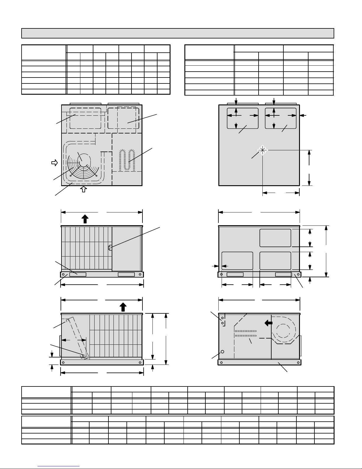
Unit Dimensions − inches (mm)
Model
Model
Model
Model
CORNER WEIGHTS lbs. (kg)
Model
Number
12CHP024 77 35 56 25 61 28 82 37
12CHP030 86 39 63 29 69 31 92 42
12CHP036 117 53 85 39 93 42 125 57
12CHP042 118 54 86 39 94 43 126 57
12CHP048 121 55 88 40 96 44 129 59
12CHP060 127 57 92 42 101 46 135 61
AA BB CC DD
lbs. kg lbs. kg lbs. kg lbs. kg
CENTER OF GRAVITY inches (mm)
Model
Number
12CHP024 217/8 556 261/2 673
12CHP030 217/8 556 261/2 673
12CHP036 233/4 603 311/4 794
12CHP042 233/4 603 311/4 794
12CHP048 233/4 603 311/4 794
12CHP060 23−3/4 603 31−1/4 794
AA
EE FF
inch mm inch mm
GG
BB
INDOOR
COIL
OUTDOOR
COIL
INTAKE
AIR
OUTDOOR
COIL FAN
OUTDOOR
COIL
FORKLIFT
SLOTS
(Front and
Back Only)
BASE RAIL
COMPRESSOR
CONDENSER COIL
INTAKE AIR
TOP VIEW
OUTDOOR COIL
EXHAUST AIR
FRONT VIEW
OUTDOOR COIL
EXHAUST AIR
B
N
C
BLOWER
OPTIONAL
ELECTRIC
HEAT
(Field
BASE RAIL
Installed)
REFRIGERANT
SERVICE
PORTS
ELECTRICAL
INLETS
KK
JJ
DOWNFLOW
RETURN AIR
OPENING
CENTER
OF
GRAVITY
DD
TOP VIEW BASE SECTION
B
HORIZONTAL
SUPPLY AIR
E
OPENING
K
F
BACK VIEW
C
LE
DOWNFLOW
SUPPLY AIR
OPENING
EE
FF
HORIZONTAL
RETURN AIR
OPENING
(048/060)
HORIZONTAL
RETURN AIR
OPENING
CC
J
2 (51)
J
A
M
K
BASE RAIL
FILTER
RACK
CONDENSATE
DRAIN
45/8
(117)
H
BASE RAIL
P
LEFT SIDE
Model
Number
−024 2711/16 703 455/8 1159 455/8 1159 251/4 641 113/16 46 4 102 17/8 48
−030 3111/16 805 455/8 1159 455/8 1159 291/4 743 113/16 46 4 102 17/8 48
−036, −042, −048, −060 3311/16 856 5411/16 1389 495/8 1260 317/16 799 11/8 29 61/4 159 21/4 57
Model
Number
−024 155/8 397 111/2 292 171/2 445 4 102 5 127 463/8 1179 463/8 1179
−030 155/8 397 111/2 292 171/2 445 4 102 5 127 463/8 1179 463/8 1179
−036, −042, −048, −060 171/8 435 12 305 211/2 546 55/8 143 41/8 105 551/4 1403 501/2 1283
A B C D E F G
inch mm inch mm inch mm inch mm inch mm inch mm inch mm
H J K L M N P
inch mm inch mm inch mm inch mm inch mm inch mm inch mm
D
A
27/16
(62)
Page 2
ELECTRIC
HEAT
POWER INLET
OPTIONAL
ELECTRIC HEAT
(Field Installed)
RIGHT SIDE
BLOWER
BASE RAIL
Page 3
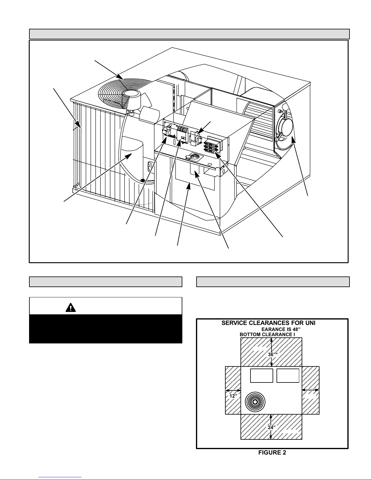
Parts Arrangement
OUTDOOR FAN
OUTDOOR COIL
COMPRESSOR
BLOWER
TRANSFORMER
INDOOR
BLOWER MOTOR
DEFROST CONTROL
BLOWER CONTROL
HEATER BLOCKOFF
(FOR OPTIONAL ELECTRIC HEAT)
FIGURE 1
Requirements
WARNING
Improper installation, adjustment, alteration, service
or maintenance can cause property damage, personal
injury or loss of life. Installation and service must be
performed by a qualified installer or service agency.
Unit should be installed in accordance with all national and
local safety codes.
NOTE − For improved start−up performance, the indoor coil
should be washed with suitable detergent to remove any
residue from manufacturing processes.
Limitations for unit and appropriate accessories must also
be observed.
The unit must not be installed with any duct system in the
outdoor air stream. The outdoor fan is not designed to oper
ate against any additional static pressure.
Minimum and maximum operating conditions must be ob
served to assure maximum system performance with mini
mum service required.
CONTACTOR
CAPACITOR
Clearances
In the U.S., units may be installed on combustible floors
made from wood or class A, B, or C roof covering material.
In Canada, units may be installed on combustible floors.
Units must be installed outdoors.
SERVICE CLEARANCES FOR UNITS
TOP CLEARANCE IS 48"
BOTTOM CLEARANCE IS 0"
REAR
36"*
RETURN SUPPLY
LEFT
12"
24"
FRONT
*Rear clearance is 36" with or 2" without an economizer.
FIGURE 2
RIGHT
12"
Page 3
Page 4

Rigging & Setting Unit
Á
Á
Exercise care when moving the unit. Do not remove any
packaging until unit is near the place of installation. A sling
assembly may be used to lift the unit. Spreaders which are
longer than the largest dimension across unit MUST be
used across the top of the unit.
CAUTION
Before lifting a unit, make sure that the weight is dis
tributed equally on the cables so that it will lift evenly.
Units may also be moved or lifted with a forklift while still in
the factory supplied packaging.
FORKS MUST BE A MINIMUM OF 42 INCHES LONG.
NOTE − Do not permit overhanging structures or shrubs to
obstruct condenser air discharge outlet or inlet.
The unit is designed to be located outdoors with sufficient
clearance for free entrance to air inlet and discharge. Loca
tion must also allow for adequate service access.
Specially designed roof curbs are available for these
units. Using any other roof curb may result in water leaking
into conditioned space. The specified roof curb is de
signed to allow water from the bottom of the condensing
coil to run off.
The unit must be installed on a solid foundation that will not
settle or shift. Adequate structural support must be pro
vided. Maintain minimum clearances as shown in illustra
tion and install unit in level position. Isolate the base from
the building structure to avoid possible transmission of
sound or vibration into conditioned space.
Unit foundation should be raised to a minimum of 3" above
finish grade. In areas which have prolonged periods of tem
perature below freezing and snowfall, the unit should be
elevated above the average snow line. Also extra precau
tion should be taken to allow free drainage of condensate
from defrost cycles to prevent ice accumulation. Unit
should not be located near walkways to prevent possible
icing of surface from defrost condensate.
Avoid placing unit near quiet areas, i.e. sleeping quarters or
study rooms. Normal operating sound levels may be objec
tionable if the unit is placed near certain rooms.
Condensate Drain
TYPICAL CONDENSATE DRAIN
Minimum Pitch
1" (25 mm) per 10’
(3 m) of line
OPEN
VENT
Trap must be deep enough to offset maximum
static difference (Generally, 3 inches minimum).
UNIT
MOUNTING
FRAME
FIGURE 3
Filters
No filters are supplied with the unit. Filters must be
installed ahead of the evaporator coil and must be cleaned
or replaced as necessary. Dirty filters will reduce the air
flow of the unit. Filters should be sized in accordance with
Table 1 below.
TABLE 1
FILTER SIZES
UNIT MODEL FILTER SIZE
12CHP−024, −030 24" X 25"
12CHP−036, −042, −048, −060 30" X 30"
Supply & Return Connections
Duct system should be designed and sized according to
the methods in Manual Q of the Air Conditioning Contrac
tors of America (ACCA).
A closed return duct system shall be used. This shall not
preclude use of economizers or outdoor fresh air intake. It
is recommended that supply and return duct connections
at the unit be made with flexible joints.
The supply and return air duct systems should be de
signed for the CFM and static requirements of the job.
They should NOT be sized to match the dimensions of
the duct connections on the unit.
The packaged heat pumps are equipped with a 3/4" fpt
coupling for condensate line connection. The drain line
must be properly trapped and routed to a suitable drain.
See illustration for proper drain arrangement. The drain
line must pitch to an open drain or pump to prevent clog
ging of the line.
CAUTION
When fastening duct system to side duct flanges on
unit, insert screws through duct flanges only. Do not
insert screws through casing. Outdoor duct must be
insulated and waterproofed.
Page 4
Page 5

Outdoor Fan Clearances
Figure 4 illustrates the critical measurements of the out
door fan system. This dimension should be checked and
fan adjusted accordingly anytime servicing of the outdoor
fan system is required.
OUTDOOR FAN CLEARANCES
A
OPTIONAL ELECTRIC HEAT INSTALLATION
UNIT MODEL NO. A
−024, −030
−036, −042, −048, −060
3"
3−1/2"
FIGURE 4
Compressors
Units are shipped with compressor mountings factory−ad
justed and ready for operation.
CAUTION
Do not loosen compressor mounting bolts.
Optional Electric Heat
The unit is fully equipped for heat pump operation without
auxiliary heat.
Installing Optional Electric Heat Section
1 − Disconnect power and open main control access.
2 − Disconnect the plug separating the high voltage
wire harness.
3 − Remove the high voltage wire harness plug and discard.
4 − Remove the heater blockoff by removing the four
screws holding it in place.
5 − Cut away insulation covering opening, using the hole
in the panel as a template.
6 − Insert the heater into the control panel and fasten in
the same mounting holes. See figure 5.
7 − Plug the heater wiring harness into the wire harness
on the control assembly.
8 − Field wiring of auxiliary heater is separate from unit
power supply. Wire power supply wiring for the heater
to appropriate connections on heater kit.
OPTIONAL
ELECTRIC
HEAT
HEATER
BLOCKOFF
FIGURE 5
Electrical
USE COPPER CONDUCTORS ONLY
All field wiring must be done in accordance with National
Electric Code recommendations, local codes and applica
ble requirements of UL or in accordance with Canadian
Electrical Code, local codes and CSA Standards. Power
wiring, disconnect means, and over−current protection are
to be supplied by installer. See unit rating plate for maxi
mum over−current protection, minimum circuit ampacity, as
well as operating voltage. The power supply must be sized
and protected according to specifications supplied. See
figure 6 for field connection of line voltage wiring and fig
ures 7 and 8 for typical wiring diagrams.
CAUTION
When connecting electrical power and control wir
ing to the unit, waterproof type connectors MUST be
used so that water or moisture cannot be drawn into
the unit during normal operation.
208/230 LINE VOLTAGE WIRING
CONTACTOR
FUSED DISCONNECT SWITCH
(FURNISHED BY INSTALLER)
L1
GROUND
LUG
NOTE − If 208 voltage is supplied, transformer connections must be
made.
FIGURE 6
L2
Page 5
Page 6

Typical Wiring Diagram
(Does not Include 12CHP060)
12CHP Series Heat Pump Packaged Units
FIGURE 7
Page 6
Page 7

Typical Wiring Diagram
12CHP060 Series Heat Pump Packaged Units
FIGURE 8
Page 7
Page 8

Unit must be grounded with separate ground conductor.
18 20
SUCTION
LIQUID
The unit wiring diagram is located inside the unit access
panel. Low voltage control wiring are pigtail leads located
below the main control box and are color coded to match
the connection called out on the wiring schematic.
general guide. These tables should not be used for charg
ing the unit. Minor variations in these pressures may be
expected due to differences in installations. Significant
differences could mean that the system is not properly
charged or that a problem exists with some component in
the system. Used carefully, this table could serve as a use
ful service guide. Table 3 should be used when unit is
If any of the original unit wiring is replaced, the same size
and type wire must be used. Electrical wiring must be
sized to carry minimum circuit ampacity marked on the
unit. Each unit must be wired with a separate branch cir
cuit and be properly fused.
charged during the heating mode. If outdoor ambient is
below 45°F, run unit through defrost cycle first, wait 15
minutes for system pressures to stabilize, then take pres
sures. Data in table 3 is based on 70°F dry bulb return air.
Data in table 4 is based on 80°F dry bulb / 67°F wet bulb
return air. Allow unit operation to stabilize before taking
System Performance
For maximum performance of this heat pump system, the
pressure readings.
TABLE 2
SUCTION SUPERHEAT TABLE
operating temperatures and pressures should be
checked and superheat determined at Standard ARI test
UNIT MODEL NO.
conditions of 82_F outdoor − 80_F indoor dry bulb/67_F
wet bulb. If superheat measured deviates from values in
table below, refrigerant charge should be adjusted ac
cordingly for maximum performance.
Verify system performance using table 3 or table 4 as a
12CHP−030, −036
12CHP−024
12CHP−030
12CHP−036
12CHP−042, −048, −060
TABLE 3
NORMAL OPERATING PRESSURES −− HEATING MODE
70°F db RETURN AIR AIR TEMPERATURE ENTERING OUTDOOR COIL (°F)
SUCTION SUPERHEAT
82_F OD minus 80_F IDDB
/ 67_F IDWB
18 − 20_
MODEL PRESSURE 0° 5° 10° 15° 20° 25° 30° 35° 40° 45° 50° 55° 60°
12CHP−024 17 20 24 28 33 38 43 49 55 62 69 74 81
12CHP−030 14 17 21 25 29 34 39 45 51 56 63 70 78
12CHP−036
12CHP−042
12CHP−048 15 18 22 26 30 35 40 45 51 55 62 68 76
12CHP−060 14 17 21 25 29 34 39 44 50 54 61 67 75
12CHP−024 181 191 200 209 219 228 237 247 256 265 275 284 293
12CHP−030 168 173 179 184 189 195 200 205 211 216 221 227 232
12CHP−036
12CHP−042
12CHP−048 203 211 220 229 237 246 255 263 272 281 289 298 307
12CHP−060 163 170 177 183 190 197 203 210 217 223 230 237 243
14 17 21 25 29 34 39 45 51 56 63 70 78
16 19 23 27 31 36 41 45 51 55 62 68 76
165 172 178 184 191 197 203 210 216 222 229 235 241
167 174 181 187 194 201 207 214 221 227 234 241 247
Page 8
Page 9

TABLE 4
SUCTION
LIQUID
NORMAL OPERATING PRESSURES −− COOLING MODE
80°F db / 67°F wb
RETURN AIR
MODEL PRESSURE 65° 70° 75° 80° 82° 85° 90° 95° 100° 105° 110° 115° 125°
12CHP−024 78 79 81 82 83 84 85 87 89 90 92 93 96
12CHP−030 78 79 81 82 83 84 85 87 89 90 92 93 96
AIR TEMPERATURE ENTERING OUTDOOR COIL (°F)
12CHP−036
12CHP−042
12CHP−048 78 79 80 82 82 83 84 85 86 87 88 90 92
12CHP−060 78 79 80 82 82 83 84 85 86 87 88 90 92
12CHP−024 140 155 170 184 190 199 213 228 243 257 272 286 316
12CHP−030 145 159 173 187 193 202 216 230 244 258 273 287 316
12CHP−036
12CHP−042
12CHP−048 164 180 196 213 219 229 245 261 277 293 309 326 358
12CHP−060 166 182 198 214 220 229 245 261 277 293 308 324 356
LIQUID
Sequence of Operation
75 77 80 82 83 84 87 89 91 94 96 98 103
80 81 82 84 84 85 86 87 88 89 90 92 94
146 161 176 191 197 206 221 236 251 266 281 296 326
155 170 185 200 206 215 230 245 260 275 290 305 335
The defrost control will initiate a defrost cycle if time period
has elapsed and the defrost sensor detects a temperature
Blower Delay − Cooling
When the thermostat is in the cooling mode, the O circuit is
powered which energizes the reversing valve. Upon cool
ing demand, the thermostat closes circuit R and Y. Closing
R and Y closes unit contactor starting compressor and out
door fan. Thermostat automatically closes R to G circuit
which also brings on the indoor blower at the same time.
Upon satisfying cooling demand, thermostat will open
above circuits and open main contactor, stopping com
pressor and outdoor fan.
Blower Delay − Heating
below freezing. At the start of defrost cycle, the defrost con
trol will energize the reversing valve solenoid, shifting the
reversing valve and de−energizing the outdoor fan. The de
frost relay will also close energizing tempering heat for in
creased comfort during defrost , if the unit is so equipped.
The unit will remain in the defrost mode until the defrost
sensor has determined that the frost has been removed
from the coil or a 10 minute time period has elapsed.
DEFROST CONTROL TEST AND
TIME PIN LOCATIONS
JUMPER SHOWN ON T2 PIN
Upon heating demand the thermostat closes circuit R to Y,
closing unit contactor, starting compressor and outdoor
fan. The reversing valve is not energized in the heating
mode. The thermostat again automatically brings on the in
door blower at the same time. Upon satisfying heating de
mand, the thermostat opens above circuits and stops unit
operation.
T1T2T3
Defrost Cycle
If outdoor ambient conditions are such that frost forms on
the outdoor coil, the defrost control monitors the need for
and initiates and terminates defrost cycles as necessary to
maintain system performance. The defrost control is time/
temperature initiated and temperature terminated with a
maximum defrost time (time−out) of 10 minutes. Time be
tween defrost cycles is pre−set at 60 minute intervals at the
factory, but can be field adjusted between 30, 60 or 90 min
utes. See figure 9 for field adjustment of defrost timing.
DEFROST
TEST PINS
T1 = 30 MINUTES
T2 = 60 MINUTES
T3 = 90 MINUTES
DEFROST TIME
PINS
(T1, T2, T3)
FIGURE 9
The defrost control is also equipped with a set of test pins to
aid in troubleshooting of the defrost system. The following
is a brief outline of the testing of the defrost system.
Page 9
Page 10

Defrost sensor will be closed at 32_ F or below. If tempera
tures are such that switch is not closed, jumper between
defrost sensor terminals on defrost control.
Start system in Heating Operation.
Jumper test pins. A 1/4" quick connect terminal crimped
onto a solid wire or brazing rod works well for test jumper.
Closing test pins speeds up time interval by a factor of 256.
Defrost Control Defrost Test Cycle Time
T1−30 minutes 7 seconds
T2−60 minutes 14 seconds
T3−90 minutes 21 seconds
After closing test pins and appropriate cycle time has
elapsed, the reversing valve should shift to defrost mode
and outdoor fan should stop. After 2 seconds of defrost op
eration, reversing valve should shift back to heating opera
tion and outdoor fan should start.
Adjustments − 12CHP060 Only
12CHP060 units are equipped with a variable speed indoor
blower motor. The blower speed is factory−set and should
not require field adjustment; however, air volume can be in
creased by 5 percent, if necessary. Follow the procedure
below.
1 − Disconnect power.
2 − Locate the blower control board wiring harness.
3 − To increase air volume (CFM) in the cooling mode, use a
pin extractor to remove the wire from harness pin posi
tion 5 (violet wire).
4 − To increase air volume (CFM) in the heating mode,
use a pin extractor to remove the wire from harness
pin position 11 (pink wire)
NOTE − If a pin extractor is not available, cut the wire and
tape off both ends.
Maintenance
Periodic inspection and maintenance normally consists of
changing or cleaning filters and (under some conditions)
cleaning the coils.
WARNING
Electric shock hazard. Can cause inju
ry or death. Before attempting to per
form any service or maintenance, turn
the electircal power to unit OFF at dis
connect switch(es). Unit may have
multiple power suppplies.
Filters
Not supplied. Inspect once a month. Replace disposable or
clean permanent type as necessary. DO NOT replace per
manent type with disposable.
Outdoor Motor
The outdoor fan motor is permanently lubricated and re
quires no maintenance.
Outdoor Coil
Dirt should not be allowed to accumulate on the outdoor
coil surface or other parts in the air circuit. Cleaning should
be as often as necessary to keep coil clean. Use a brush,
vacuum cleaner attachment, or other suitable means. If
water is used to clean coil, be sure power to the unit is shut
off prior to cleaning.
NOTE − Care should be used when cleaning the coil so that
the coil fins are not damaged.
Repair Parts List
When ordering parts, include the complete model number
and serial number which are printed on the rating plate lo
cated on the unit.
Control Group
Transformer
Blower Group
Blower Housing Assembly
Blower Wheel
Blower Motor
Blower Motor Mount
Blower Motor Capacitor (if used)
Fan Blade
Fan Motor
Fan Motor Capacitor
Cooling Group
Compressor
Coil−Evaporator
Drier
Cap Tube or Expansion Valve
Contactor
Time Delay Relay
Fan Relay
Capacitor
Coil−Condenser
Defrost Control
Reversing Valve Solenoid
Description Kit Number LENNOX Cat. Number
Low Ambient Control ALOAM111−1 42K88
High Pressure Cut−out Kit AHPSW436−1 42K89
Outdoor Thermostat LB−29740BA 56A87
Timed Off Control ATIMR446−1 42K90
Accessories
Page 10
 Loading...