

Lennox 10T50 Installation And Setup Manual
Equipment Interface
Module Installation and
Setup Guide
(10T50)
507240-03
3/2019
Supersedes 11/2018
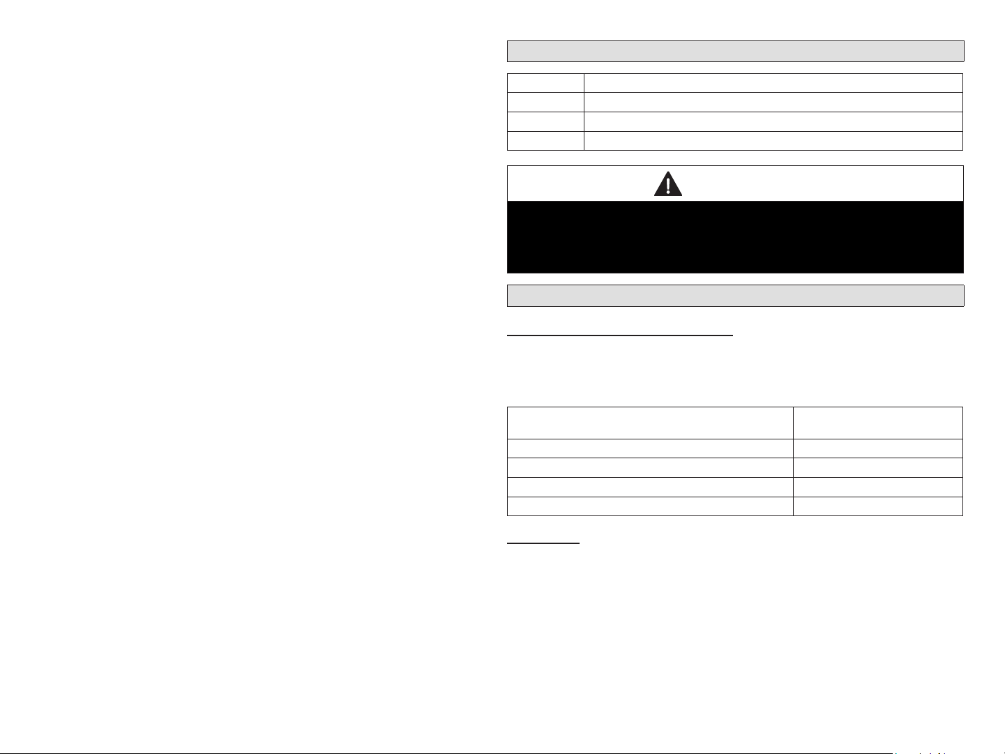
TABLE OF CONTENTS
Shipping and Packing List .................................................................2
Application and Requirements ..........................................................2
Indoor Transformer Requirements ................................................... 2
Equipment ....................................................................................... 2
Installation ...........................................................................................5
Conguration Setup ........................................................................... 5
EIM, 24VAC Furnace and Lennox Communicating Heat Pumps .... 5
EIM, Lennox Communicating Furnace and 24VAC Heat Pump ...... 5
Unit Type Jumpers ........................................................................... 5
Heat Stage Jumper Positions .......................................................... 6
Air Temperature Sensor Connections .............................................. 6
Lennox Communicating Terminal Connections ............................... 6
Dual-Fuel Terminal Connections ..................................................... 7
Conventional Terminal Connections ................................................ 7
LED Indicators ................................................................................. 7
Soft Disable ..................................................................................... 8
iComfort Wi-Fi Commissioning (Conventional Outdoor Unit) .......... 8
iComfort S30 Commissioning (Conventional Outdoor Unit) ............ 9
Operating Environment Specications ............................................9
Unit Dimensions ...............................................................................10
Duel-Fuel Operations .......................................................................10
Field Wiring ....................................................................................... 11
Alert Codes and Troubleshooting ...................................................17
Shipping and Packing List
Quantity Description
1 Equipment Interface Module.
1 Installation and setup guide
1 Warranty certicate
WARNING
Improper installation, adjustment, alteration, ser vice or maintenance can
cause property damage, personal injury or loss of life.
Installation and service must be performed by a li censed professional
HVAC installer (or equivalent) or a service agency.
Application and Requirements
Indoor Transformer Requirements
The following lists the required indoor unit transformer rating (VA) for
specic congurations.
Table 1. System VA Loading Chart
Conguration
2-Stage HP, 3-Stage Electric heat 70
2-Stage HP, 2-Stage Furnace (with tempering) 70
2-Stage HP, 2-Stage Furnace (without tempering) 50
2-Stage AC, 2-Stage Furnace 40
Equipment
The Equipment Interface Module (EIM) is used with an Lennox
communicating thermostat (iComfort Wi-FI® or iComfort® S30) using the R,
i+, i-, and C terminals. The EIM is the interface between non-communicating
HVAC equipment and Lennox communicating HVAC equipment. The
control supports the following equipment applications:
Minimum Transformer Rating
(VA)
NOTE: EIM will support single-stage outdoor units with single-stage or
variable-stage indoor furnaces.
2
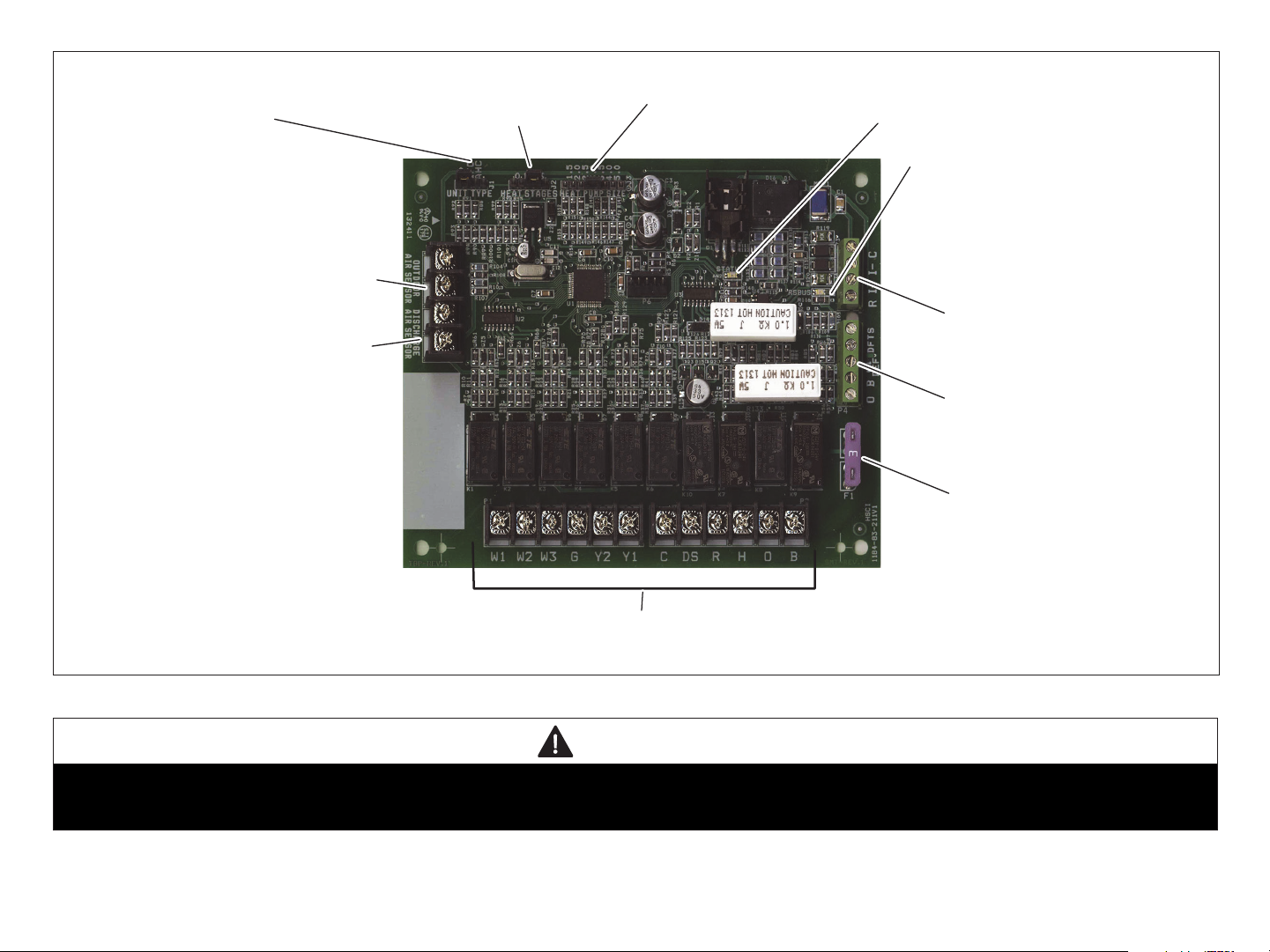
OUTDOOR AIR SENSOR
CONNECTIONS
DISCHARGE AIR
SENSOR CONNECTIONS
LENNOX COMMUNICATING
CONNECTIONS
NON-COMMUNICATING TERMINALS
STATUS LED
COMMUNICATION INDICATOR
LED
DUAL-FUEL
CONNECTIONS
UNIT TYPE JUMPER
TERMINALS
HEAT STAGES
JUMPER TERMIINALS
HEAT PUMP CAPACITY
JUMPER TERMINALS
3 AMP FUSE
Figure 1. Terminals and LEDs
CAUTION
Electrostatic discharge can aect electronic components. Take precautions during unit installation and service to protect the unit’s electronic controls.
Precautions will help to avoid control exposure to electrostatic discharge by putting the unit, the control and the technician at the same electrostatic
potential. Neutralize electrostatic charge by touching hand and all tools on an unpainted unit surface before performing any service procedure
3
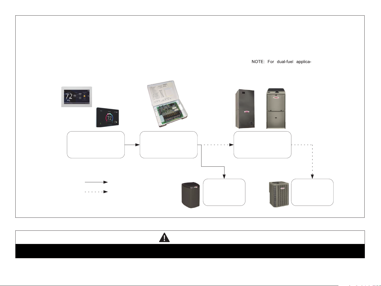
ICOMFORT
WI-FI
EIM with Air Hander or Furnace (Indoor Unit)
and either a Air Conditioner or Heat Pump
(Outdoor Unit)
tions, additional components
may need to be added, see figure
5 on page 8.
ICOMFORT
S30
Lennox Communcating
Thermostat
Wiring Legend
4−wire communicating
24VAC conventional
Equipment Interface
Model (EIM)
Lennox
communicating
Air Conditioner or
Heat Pump
(Outdoor Unit)
Figure 2. System View
24VAC Air Handler or
Furnace (Indoor Unit)
24VAC Air
Conditioner
or Heat Pump
(Outdoor Unit)
WARNING
Controls in this module are sensitive to moisture. Do NOT secure this module to the sheet metal cabinet where moisture may condense during periods
of high humidity. Secure the module to a nearby wooden stud, if possible.
4
Installation
HP IFC AHC
2. Set the EIM Heat Stage Jumper (see “Table 3. Heat Stage Jumpers” on
page 6) to the applicable number of furnace heat stages or number
of electric heat stages.
IMPORTANT
The Lennox communicating thermostat paired with the Equipment
Interface Module (EIM) will work with most 24VAC furnaces, air handlers,
air conditioners and heat pumps (up to 2-stages of cooling and 3-stages
of heat).
The Lennox communicating thermostat without the Equipment Interface
Module (EIM) will work with Lennox communicating HVAC equipment.
1. Remove the module cover.
2. Mount the Equipment Interface Module (EIM) near the indoor unit.
3. Use the wiring diagrams reference in the sectoin titled “Field Wiring”
on page 11 to complete the wiring connections for the specic
application and conguration.
Conguration Setup
How the EIM is congured is determined by the system components.
NOTE: Changing jumper positions after the control has been powered-up
requires recommissioning for the change to be recognized.
NOTE: When the Equipment Interface Module is replaced, recommissioning
the Lennox communicating thermostat will also need to be reaccomplished. See the Lennox communicating thermostat Setup
Guide for recommissioning procedure.
The following examples are two typical congurations used with the EIM.
There are other applications as well and are address in the wiring diagrams
section titled “Field Wiring” on page 11. Those diagrams will indicate all
required jumper settings on the EIM and wiring connections.
3. Use the Lennox communicating thermostat to complete the
commissioning procedure.
EIM, Lennox Communicating Furnace and 24VAC Heat Pump
See “Figure 12. Dual-Fuel - Lennox Communicating Furnace with
Conventional Heat Pump” on page 12f or wiring details.
1. Set the EIM Unit Type Jumper to Heat Pump.
2. Set the EIM Heat Stage Jumper (see “Table 3. Heat Stage Jumpers”
on page 6) to the applicable number of heat pump heating stages.
3. Use the Lennox communicating thermostat to complete the
commissioning procedure.
NOTE: For two-stage heat pump go to the heat pump defrost control,
locate P3 - low ambient thermostat pins and disable this function
by removing the installed jumper and relocating it to one pin only.
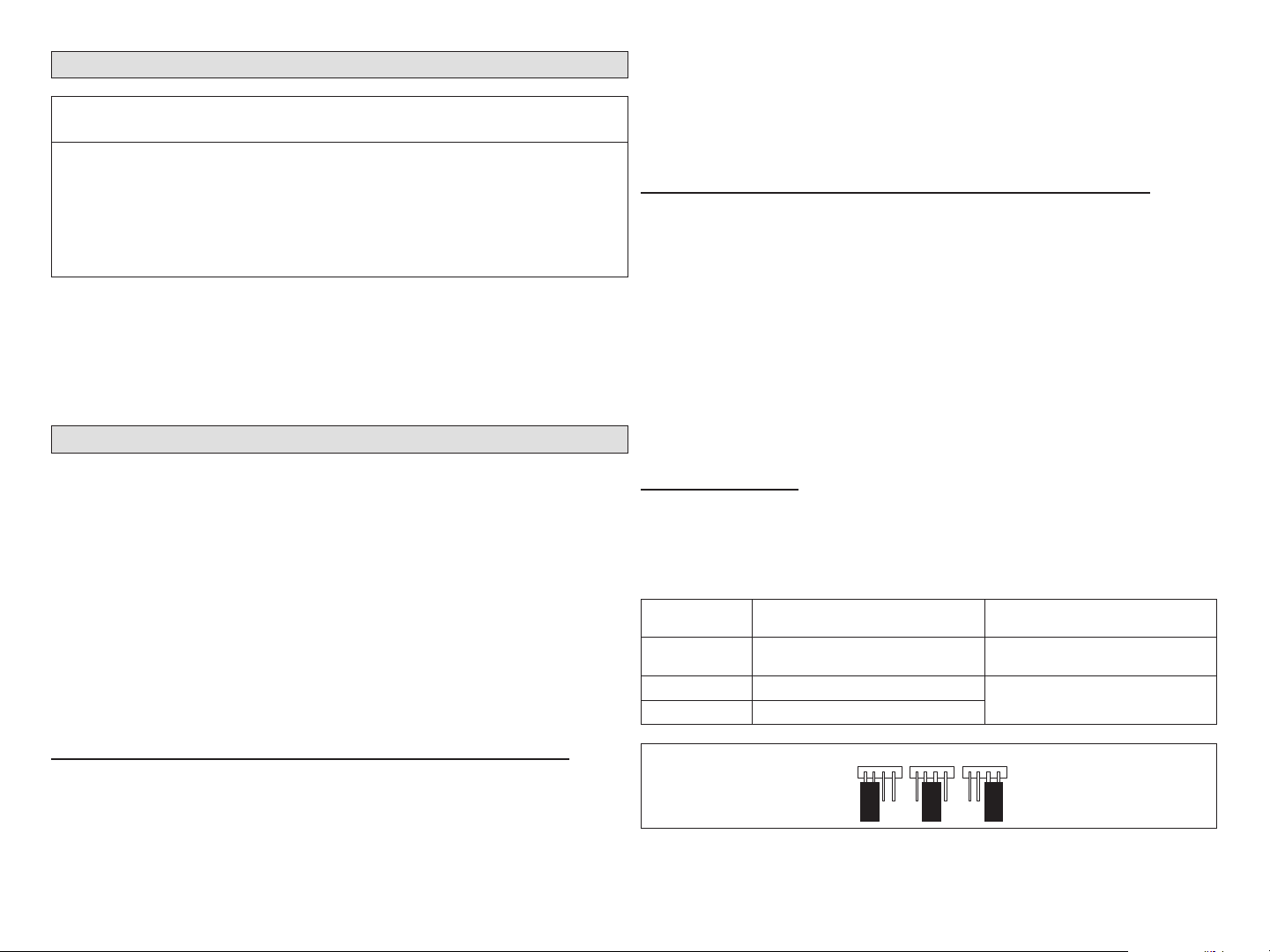
Unit Type Jumpers
Set the unit type jumper for the type of indoor unit being by using the
following table and gure. The factory default setting is IFC. If jumper is
missing from the jumper pins, then alarm 130 is activated.
Table 2. Unit Type Jumpers Positions
Jumper
Position
HP
IFC Conventional Furnace
AHC Conventional Air Handler
Indoor Unit Outdoor Unit
Lennox Communicating Furnace
Conventional Heat Pump
Conventional Heat Pump or air
conditioner
EIM, 24VAC Furnace and Lennox Communicating Heat Pumps
See “Figure 13. Dual-Fuel - Conventional Furnace with Lennox Communicating
Heat Pump” on page 12 for wiring details.
1. Set the EIM Unit Type Jumper to IFC.
Figure 3. Unit Type Jumper Positions
5
Heat Stage Jumper Positions
0 1 2 3
0
5
0
5
0
The factory default setting is position 2 (two heat stages). If jumper is
missing from the jumper pins, then alarm 130 is activated. Depending on
the type of equipment and system set up being used:
• Set the number of stages of electric heat (air handler) when jumper pin
selection is AHC selection.
• Set the number of stage of gas heat (Furnace) when jumper pin selection
is IFC.
• Set the number of stages of the compressor when jumper pin selection
is HP.
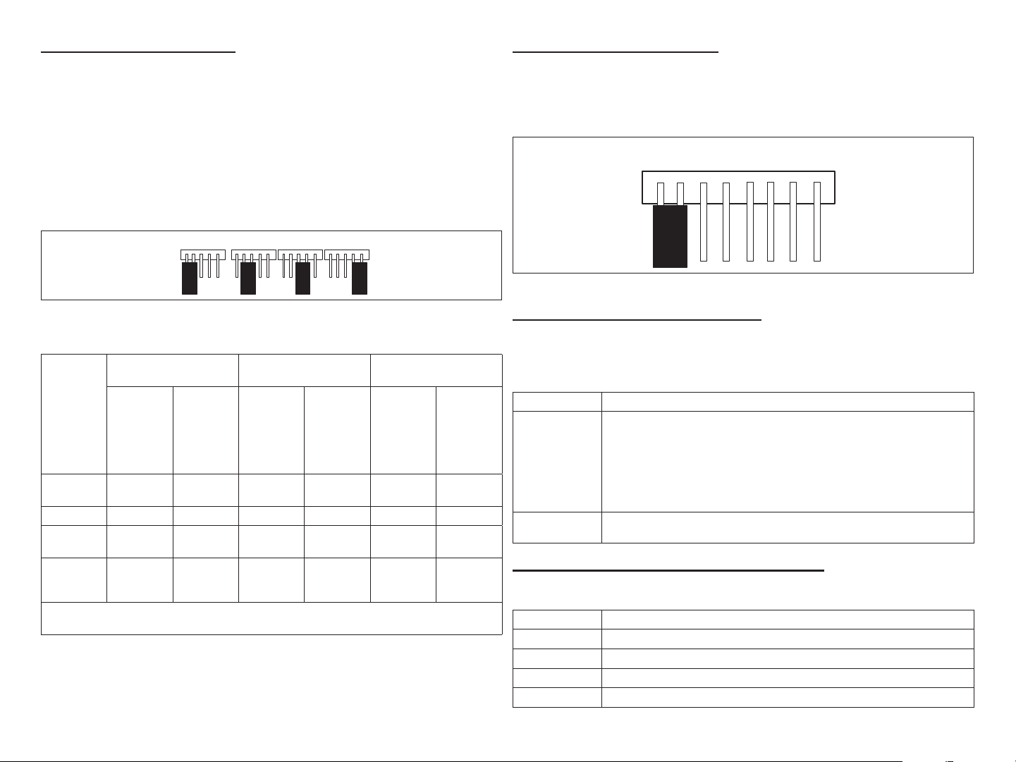
24VAC Heat Pump Size Setting
Heat pump size must be congured when using a non-communicating heat
pump using the Heat Pump Size jumper (see gure 4 and table 5). Factory
default setting is for 3.0 (3-ton). If jumper is missing from jumper pins then
alarm 130 is activated.
1.52.
Figure 5. Conventional Heap Pump Capacity Jumper Setting
2.
3.
3.
4.05.
Figure 4. Heat Stage Jumper Positions
Table 3. Heat Stage Jumpers
Air Handler Heat
Stages
Electric Heat
Number of
Label
(Position)
0
1 1 100% 1 100% 1 100%
2
(default)
3 3
NOTE: If jumper is missing, setting defaults to single stage. Changing jumper position
Stages
No Electric
Heat
2
after power-up requires recommission for the change to be recognized.
Percentage
0 1 100% 1 100%
50%,
100%
33.5%,
66.5%,
100%
Furnace Heat Stages Heat Pump Stages
Stage
Gas Stages
Number of
2
2
Percentage
Stage
70%.
100%
70%,
100%
Stages
Compressors
Number of
2
2
Percentage
70%.
100%
70%.
100%
Stage
Air Temperature Sensor Connections
Refer to “Figure 1. Terminals and LEDs” on page 3 for various terminal
locations.
Table 4. Outdoor Air and Discharge Air Sensors
Label Function / Description
Show ambient temperatures (optional if weather feed is acceptable or
outdoor unit is a communicating unit; use X2658 Outdoor Sensor - 2
Outdoor Air
Sensor
Discharge Air
Sensor
terminals).
NOTE: Wiring distance between the EIM and the outdoor temperature
sensor can not exceed 150 feet (45 meters) when wired with
minimum 22AWG (Recommend) 18AWG dedicated twoconductor thermostat cable.
Optional for diagnostics of indoor air; use 88K38 Discharge Air Sensor 2 terminals.
Lennox Communicating Terminal Connections
Table 5. Communicating Terminals
Label Function / Description
R 24VAC communication power Input
i+ Communication high – data line
i- Communication low – data line
C 24VAC communication common power Input
6
 Loading...