

Lennox 10GCS-024, 10GCS-030, 10GCS-036, 10GCS-048, 10GCS-060 Installation Instructions Manual
...Page 1

LENNDX
INSTALLATION
,1,_2000Lennox industries Inc
Daltas, Texas, USA
10GCS
12GCS
RETAIN THESE INSTRUCTIONS
FOR FUTURE REFERENCE
INSTRUCTIONS
10GCS & 12GCS
SERIES UNITS
GAS PACKAGED UNITS (2-5 TONS)
Armstrong # 38152A058
504,245M
08/03
Supersedes 05/00
Unit Dimensions ................................ 2
Parts Arrangement ............................. 4
Shipping & Packing List ......................... 4
General ....................................... 4
Requirements .................................. 4
Clearances .................................... 5
Rigging & Setting Unit ........................... 5
Condensate Drain .............................. 6
Filters ......................................... 6
Supply & Return Connections .................... 6
Installing Vent Hood ............................. 6
Combustion Discharge .......................... 6
Compressors .................................. 7
Gas Piping .................................... 7
LPG/Propane Units, Tanks, & Piping .............. 8
Electrical ...................................... 8
Sequence of Operation ......................... 11
Condenser Fan Clearances ..................... 12
Start-up Check List ............................ 13
Heating Start-up ............................... 13
Burner Adjustments ............................ 14
Manifold Gas Pressure Adjustment ............... 14
High Altitude Information ....................... 14
Unit Controls .................................. 14
Maintenance .................................. 15
Troubleshooting ............................... 15
Led Codes & Flash Rates ....................... 16
Repair Parts & Accessories ..................... 16
_pu Technical
blications
Litho U.S.A.
j -&WARNING
Do not store or use gasoline or other
flammable vapors and liquids in the
vicinity of this or any other ap-
pliance.
Installation and service must be
performed by a qualified installer,
service agency or the gas supplier.
08/03
IIIIIIIIIIIIIIIIIIIIIIIIIIIIIIIIIIIIIIII
WHAT TO DO IF YOU SMELL GAS:
• Do not try to light any appliance.
• Extinguish any open flames.
• Do not touch any electrical switch; do not
use any phone in your building.
• Immediately call your gas supplier from a
neighbor's phone. Follow the gas supplier's
instructions.
• If you cannot reach your gas supplier, call
the fire department.
504,245M
Page 1
IIIllllllllllllllllllllllllllllllHlllllllll
Page 2
Model
Number
t0GCS-024
t0GCS-030
t0GCS-036
10GCS-042
10GCS-048
10GCS-O6O
EVAPORATOR _
COIL
CONDENSER
COIL I_
INTAKE
AIR
CONDENSER
COIL FAN
CONDENSER
COIL
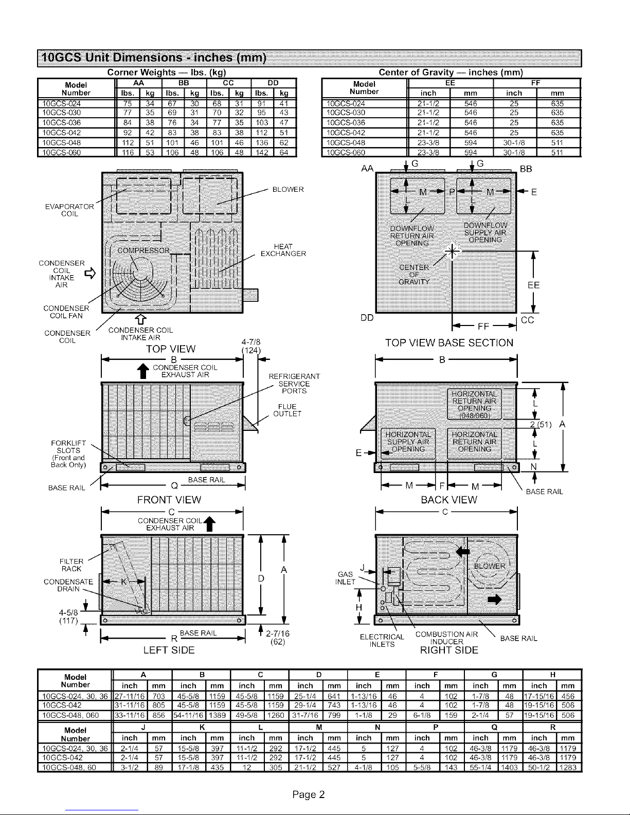
Corner Weights -- Ibs. (kg)
AA BB CC DD
Ibs, kg Ibs. kg Ibs, kg Ibs. kg
75 34 67 30 68 3t 9t 4t
77 35 69 3t 70 32 95 43
84 38 76 34 77 35 t03 47
92 42 83 38 83 38 t12 5t
tt2 5t t01 46 t01 46 t36 62
116 53 106 48 106 48 142 64
.9.
CONDENSER COIL
INTAKE AIR
TOP VIEW
CONDENSER COIL
EXHAUST AIR
4-7/8
(124)
_i rI-REFRIGE RANT
BLOWER
HEAT
EXCHANGER
SERVICE
PORTS
FLUE
OUTLET
Center of Gravity -- inches (mm)
Model EE
Number inch mm
t OGCS-024 2t -1/2 546
t OGCS-03O 21-1/2 546
t OGCS-036 2t -1/2 546
t OGCS-042 21-1/2 546
t OGCS-048 23-3/8 594
1OGCS-O6O 23-3/8 594
AA
G G
DD
inch
25
25
25
25
30-t/8
30-1/8
FF
mm
635
635
635
635
5tt
511
BB
FORKLIFT
SLOTS
(Front and
Back Only)
BASERAIL
BASE RAIL
Q
FRONT VIEW
C
CONDENSER COIL_h,
EXHAUST AIR m
FILTER /
RACK
CONDENSATE
DRAIN
4-5/8 _
(117) ____ _ R BASE RAIL _!
LEFT SIDE
Model A B C D E F G H
Number inch mm inch mm inch mm inch mm inch mm inch mm inch mm inch mm
10GCS-024 t 30 t 36 27-11/16 703 45-5/8 1159 45-5/8 1159 25-1/4 641 1-13/16 46 4 102 1-7/8 48 17-15/16 456
10GCS-042 3t-11/16 805 45-5/8 1159 45-5/8 1159 29-1/4 743 1-13/16 46 4 102 1-7/8 48 19-15/16 506
10GCS-048,060 33-11/16 856 54-11/16 1389 49-5/8 1260 3t-7/16 799 1-1/8 29 6-1/8 159 2-1/4 57 19-15/16 506
Model J K L M N P Q R
Number inch mm inch mm inch mm inch mm inch mm inch mm inch mm inch mm
10GCS-024 t 30 t 36 2-1/4 57 15-5/8 397 11-1/2 292 17-1/2 445 5 127 4 102 46-3/8 1179 46-3/8 1179
10GCS-042 2-1/4 57 t5-5/8 397 tt-1/2 292 t7-t/2 445 5 t27 4 t02 46-3/8 tt79 46-3/8 t179
10GCS-048, 60 3-1/2 89 17-1/8 435 12 305 2t-1/2 527 4-1/8 105 5-5/8 143 55-1/4 1403 50-1/2 1283
4
-(
A
2 -7/16
(62)
M M
J
GAS
INLET
ELECTRICAL COMBUSTION AIR
INLETS INDUCER BASE RAIL
BACK VIEW
BASE RAIL
C
RIGHT SIDE
Page 2
Page 3
Model
Number
12GCS-024
12GCS-030
t2GCS-036
t2GCS-042
12GCS-048, -060
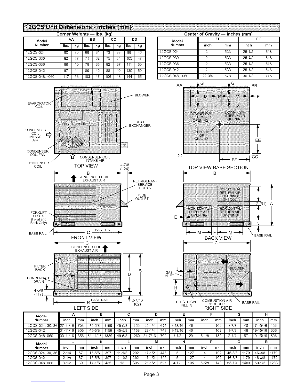
Corner Wei_ hts -- Ibs.
AA BB ''CC DD
Ibs, kg Ibs, kg Ibs, kg Ibs, kg
80 36 69 3t 73 33 99 45
82 37 71 32 75 34 103 47
89 40 78 35 82 37 tll 50
97 44 89 40 88 40 t30 59
117 53 103 47 106 48 144 65
Center of Gravity -- inches (mm)
Model
Number inch mm inch
t2GCS-024 2t 533 25-t/2
t2GCS-030 2t 533 25-t/2
12GCS-036 2t 533 25-1/2
t2GCS-042 2t 533 25-t/2
t2GCS-048, -060 22-3/4 578 30-1/2
AA
EE
G
FF
mm
648
648
648
648
775
BB
EVAPORATOR /
COIL
CONDENSER
COIL _D
INTAKE
AIR
CONDENSER
COILFAN
CONDENSER
COIL
FORKLIFT
SLOTS
(Front and
Back Only)
BASE RAIL
i :!
/
/ '_ CONDENSER COIL
/
t CONDENSER COIL
INTAKE AI R
TOP VIEW 4-7/8
B r_11241_-R
EXHAUST AIR EFRIGERANT
Q BASE RAIL _---I _ M'_I FI_ M "_P
FRONT VIEW BACK VIEW
:_ BLOWER
J
m
i :!i
i
!
HEAT
j EXCHANGER
3
SERVICE
PORTS
FLUE
OUTLET
E
EE
1
DD
FF "_4 CC
TOP VIEW BASE SECTION
B _--
L
V
[(51) A
E-ID
\ BASE RAIL
CONDENSER COIL,_IL
C = = C
EXHAUST AIR II
FILTER
RACK
DRAIN
I BASE RAIL
R ELECTRICAL COMBUSTION AIR
LEFT SIDE INLETS RIGHTINDUCERSIDE BASERAIL
Model A B C D E F G H
Number inch mm inch mm inch mm inch mm inch mm inch mm inch mm inch mm
12GCS-024, 30, 36 27-11/16 703 45-5/8 1159 45-5/8 1159 25-1/4 641 1-13/16 46 4 102 1-7/8 48 17-15/16 456
12GCS-042 3t-tl/16 805 45-5/8 tt59 45-5/8 tt59 29-t/4 743 t-13/16 46 4 t02 t-7/8 48 t9-t5/t6 506
12GCS-048, 060 33-tl/16 856 54-tl/16 t389 49-5/8 t260 3t-7/16 799 t-1/8 29 6-t/8 t59 2-1/4 57 t9-t5/t6 506
Model
Number inch mm inch mm inch mm inch mm inch mm inch mm inch mm inch mm
12GCS-024, 30, 36 2-1/4 57 15-5/8 397 11-1/2 292 17-1/2 445 5 127 4 102 46-3/8 1179 46-3/8 1179
12GCS-042 2-1/4 57 15-5/8 397 11-1/2 292 17-1/2 445 5 127 4 102 46-3/8 1179 46-3/8 1179
12GCS-048, 060 3-1/2 89 17-1/8 435 12 305 21-1/2 527 4-1/8 105 5-5/8 143 55-1/4 1403 50-1/2 1283
J K L M N P Q R
Page 3
GAS
J
Page 4
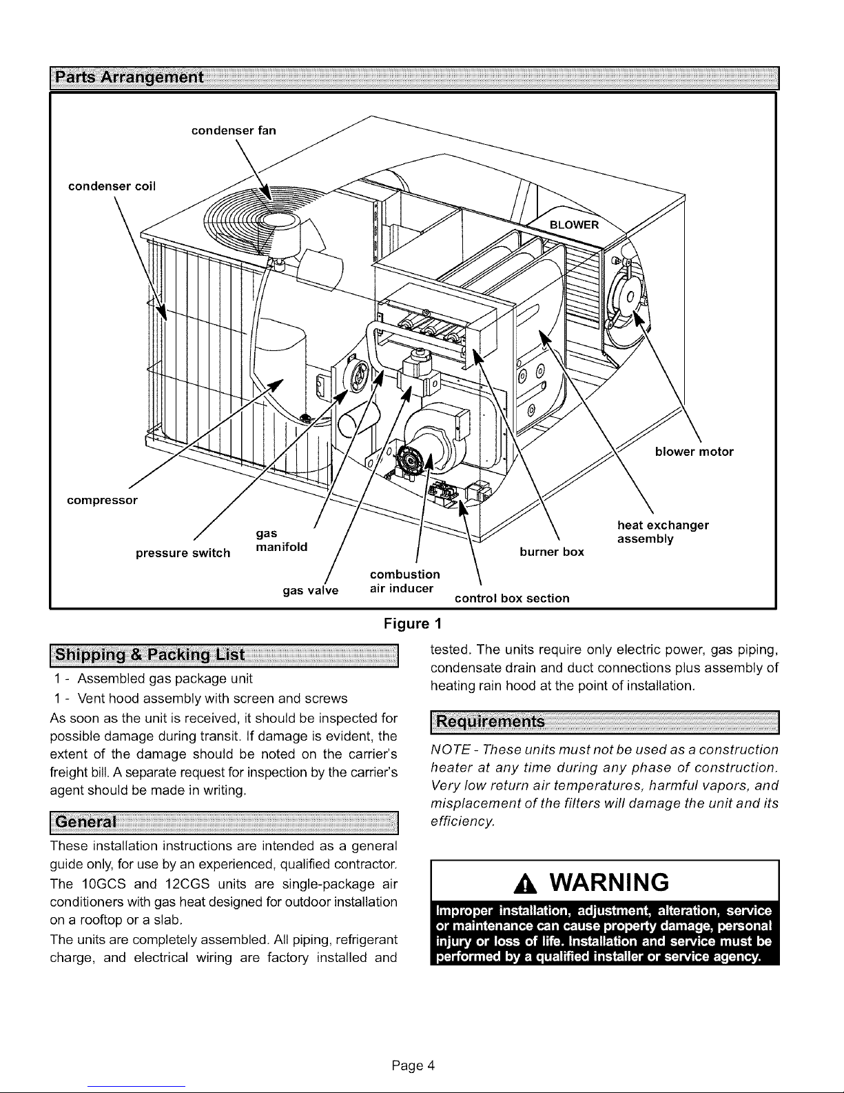
condensercoil
compressor
condenserfan
blower motor
gas
pressure switch
manifold
gas valve
combustion
air inducer
Figure 1
1 - Assembled gas package unit
1 - Vent hood assembly with screen and screws
As soon as the unit is received, it should be inspected for
possible damage during transit. If damage is evident, the
extent of the damage should be noted on the carrier's
freight bill.A separate request for inspection by the carrier's
agent should be made in writing.
These installation instructions are intended as a general
guide only, for use by an experienced, qualified contractor.
The 10GCS and 12CGS units are single-package air
conditioners with gas heat designed for outdoor installation
on a rooftop or a slab.
The units are completely assembled. All piping, refrigerant
charge, and electrical wiring are factory installed and
heatexchanger
assembly
burner box
control box section
tested. The units require only electric power, gas piping,
condensate drain and duct connections plus assembly of
heating rain hood at the point of installation.
NOTE - These units must not be used as a construction
heater at any time during any phase of construction.
Very low return air temperatures, harmful vapors, and
misplacement of the filters will damage the unit and its
efficiency.
WARNING
Page 4
Page 5
WARNING
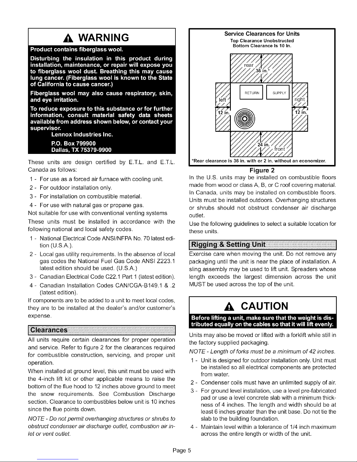
Service Clearances for Units
Top Clearance Unobstructed
Bottom Clearance Is 10 In.
right
ill
12 in.
These units are design certified by E.T.L and E.T.L
Canada as follows:
1 - For use as a forced air furnace with cooling unit.
2 - For outdoor installation only.
3 - For installation on combustible material.
4 - For use with natural gas or propane gas.
Not suitable for use with conventional venting systems
These units must be installed in accordance with the
following national and local safety codes.
1 - National Electrical Code ANSI/NFPA No. 70 latest edi-
tion (U.S.A.).
2 - Local gas utility requirements. In the absence of local
gas codes the National Fuel Gas Code ANSI Z223.1
latest edition should be used. (U.S.A.)
3 - Canadian Electrical Code C22.1 Part 1 (latest edition).
4- Canadian Installation Codes CAN/CGA-B149.1 & .2
(latest edition).
If components are to be added to a unit to meet local codes,
they are to be installed at the dealer's and/or customer's
expense.
*Rear clearance is 36 in. with or 2 in. without an economizer.
Figure 2
In the U.S. units may be installed on combustible floors
made from wood or class A, B, or C roof covering material.
In Canada, units may be installed on combustible floors.
Units must be installed outdoors. Overhanging structures
or shrubs should not obstruct condenser air discharge
outlet.
Use the following guidelines to select a suitable location for
these units.
Exercise care when moving the unit. Do not remove any
packaging until the unit is near the place of installation. A
sling assembly may be used to lift unit. Spreaders whose
length exceeds the largest dimension across the unit
MUST be used across the top of the unit.
Ak CAUTION
All units require certain clearances for proper operation
and service. Refer to figure 2 for the clearances required
for combustible construction, servicing, and proper unit
operation.
When installed at ground level, this unit must be used with
the 4-inch lift kit or other applicable means to raise the
bottom of the flue hood to 12 inches above ground to meet
the snow requirements. See Combustion Discharge
section. Clearance to combustibles below unit is 10 inches
since the flue points down.
NOTE - Do not permit overhanging structures or shrubs to
obstruct condenser air discharge outlet, combustion air in-
let or vent outlet.
Units may also be moved or lifted with a forklift while still in
the factory supplied packaging.
NOTE - Length of forks must be a minimum of 42 inches.
1 - Unit is designed for outdoor installation only. Unit must
be installed so all electrical components are protected
from water.
2 - Condenser coils must have an unlimited supply of air.
3 - For ground level installation, use a level pre-fabricated
pad or use a level concrete slab with a minimum thick-
ness of 4 inches. The length and width should be at
least 6 inches greater than the unit base. Do not tie the
slab to the building foundation.
4 - Maintain level within a tolerance of 1/4 inch maximum
across the entire length or width of the unit.
Page 5
Page 6

Thepackagedunitisequippedwitha3/4inchfptcoupling
forcondensatelineconnection.Plumbingmustconformto
localcodes.Use a sealingcompoundon malepipe
threads.
Thedrainlinemustbeproperlytrappedandroutedtoa
suitabledrain.Seefigure3forproperdrainarrangement.
Thedrainlinemustpitchto anopendrainor pumpa
minimumof 1inchper10feetto preventcloggingofthe
line.Sealarounddrainconnectionwithsuitablematerialto
preventairleakageintoreturnairsystem.
Drainpipingshouldnotbesmallerthandrainconnectionat
coil.Anopenventindrainlinewillsometimesberequired
dueto linelength,frictionandstaticpressure.Drains
shouldbeconstructedinamannertofacilitatefutureclean-
ing.
NOTE - The condensate drain fine MUST be trapped to
provide proper drainage.
Typical Condensate Drain
Minimum Pitch
1 in. (25 ram) per
10' (3 m) of line
open
vent
unit
Duct system should be designed and sized according to
the methods in Manual Q of the Air Conditioning
Contractors of America (ACCA).
A closed return duct system shall be used. This shall not
preclude use of economizers or outdoor fresh air intake. It
is recommended that supply and return duct connections
at the unit be made with flexible joints.
The supply and return air duct systems should be designed
for the CFM and static requirements of the job. They
should NOT be sized to match the dimensions of the
duct connections on the unit,
Ak CAUTION
The vent hood is installed by placing screen in hood and
securing with four #8 x 3/8 large blunt sheet metal screws
and four #8 flat speed nuts as shown in figure 4. Place hood
with screen in position and attach with three #8 x 1/2 sheet
metal screws using holes provided.
Vent Hood Installation
,%
Trap must be deep enough to offset maximum mounting
static difference (Generally, 3 inches minimum), frame
Figure 3
No filters are supplied with the unit. Filters must always be
installed ahead of evaporator coil and must be kept clean or
replaced. Dirty filters will reduce the airflow of the unit.
Filters sizes are shown in table 1.
Unit is equipped with an internal filter clip which is located in
indoor coil compartment attached to side of the unit drain
pan.
Table 1
Unit Filter Size
Unit Model Filter Size
-024, -030, -036 24 in. X 25 in.
-042 28 in. X 25 in.
-048 -060 30 in. X 30 in.
o
HOOD 1
screen
Figure 4
The products of combustion are discharged horizontally
through a screened opening on the gas heat side panel.
The horizontal vent system shall terminate at least 4 feet
below, 4 feet horizontally from, or 1 foot above any door,
window, or gravity air inlet into the building. The vent
system shall terminate at least 3 feet above any forced air
inlet located within 10 feet. The bottom of the vent
terminal shall be located at least 12 inches above grade.
Minimum horizontal clearance of 4 feet from electric
meters, gas meters, regulators, and relief equipment is
required.
Page 6
Page 7

Theventoutletmustbeinstalledinalocationthatprevents
buildingdegradationandmustbe consistentwith the
NationalFuelGasCode,Z223.1orCAN/CGA-B149,1&.2,
In addition to the above requirements, consideration must
be given to prevent unwanted ice build-up from the vent
condensate. The vent should not be located on the side of a
building where the prevailing winter winds could trap the
moisture causing it to freeze on the walls or on overhangs
(under eaves), The vent location should not discharge over
a sidewalk, patio or other walkway, where the condensate
could cause the surface to become slippery,
The products of combustion must not be allowed to
accumulate within a confined space and recirculate,
Units are shipped with the compressor mountings
factory-adjusted and ready for operation.
Proper sizing of gas piping depends on the cubic feet per
hour of gas flow required, specific gravity of the gas and
length of run, The current National Fuel Gas Code Z223,1
should be followed in all cases unless superseded by local
codes or gas company requirements, Refer to tables 2 and
3, In Canada see CAN/CGA B,149,1 & ,2 (latest edition),
Table 2
Gas Heat Application Data
Input Rating Output Rating Gas Capaci_
(Btu) (Btu) (FT3 / HR)
50,000 40,000 47
75,000 60,000 70
100,000 80,000 93
125,000 100,000 116
Before connecting piping, check with gas company or
authorities having jurisdiction for local codes or require-
ments. When installing gas supply piping, length of run
from gas meter must be considered in determining pipe
size for 0,5 inch w.c, maximum pressure drop. Do not
use supply pipe smaller than unit gas connection, For
natural gas unit, operating pressure at the unit gas con-
nection must be a minimum of 4.5 inch w.c. and a maxi-
mum of 13,5 w.c. For propane/LP gas units, operating
pressure at the unit gas connection must be a minimum
of 11 inches w.c. and a maximum of 13,5 inches w.c,
Table 3
Gas Pipe Capacity-FT 3 / HR
Length in Feet
10 132
20 92
30 73
40 63
50 56
60 50
70 46
80 43
90 40
100 38
Nominal Iron Pipe Size (inches)
1_ in.
3/4 in. 1 in. 1-1/4 in.
278 520 1050
190 350 730
152 285 590
130 245 500
115 215 440
105 195 400
96 180 370
90 170 350
84 160 320
79 150 305
When making piping connections, a drip leg should be
installed on vertical runs to serve as a trap for sediment or
condensate, A 1/8 inch N,RT. tap accessible for test gauge
connection must be provided in field piping upstream from
gas supply connection to unit. Install a ground joint union
between gas control manifold and the manual main shut-
off valve. See figure 5,
Compounds used on threaded joints of gas piping shall be
resistant to the action of propane/LP gases.
Drip Leg Installation
field provided
1/8 in. p
ground joint
union
manual main
shut-off
piping
support
base of unit
leg support
Figure 5
Pressure Test Gas Piping
When pressure testing gas lines, the gas valve must be dis-
connected and isolated. Gas valve can be damaged if sub-
jected to more than 0,5 psig (14 inch w.c.), See figure 6,
If test pressure is equal to or less than 0,5 psig (14 inch
w.c.) shutoff the manual main shut-off valve before pres-
sure testing to isolate unit from gas supply system.
Page 7
Page 8

Isolate Gas Valve To Pressure Test
Manual Main Shut-off Valve Will Not Hold Test
Pressures in Excess of 0.5 PSIG (14 in. w.c.)
unit
gas valve cap
Ak CAUTION
5 - The furnace and its individual manual shut-off valve
must be disconnected from the gas supply piping sys-
tem during any pressure testing of that system at test
pressures in excess of 1/2 PSIG (3,48kPa),
Fiaure 6
NOTE - Codes may require that manual main shut off valve
and union (furnished by installer) be installed ingas line exter-
nal to unit. Union must be of the ground joint type.
,WARNING
After gas piping is complete, carefully check all piping con-
nections (factory and field) for gas leaks, Use soap solution
or other preferred means.
NOTE - In case of emergency shutdown, shut off main
manual gas valve and disconnect main power to unit.
These devices should be properly labeled by installer.
The heating value of the gas may differ with locality, The
value should be checked with the local gas utility.
NQ TE - Units are shipped equipped for natural gas, but can
be converted to LPG/propane with a conversion kit.
NOTE- There may be a local gas utility requirement speci-
fying a minimum diameter for gas piping. All units require a
1/2 inch pipe connection at the gas valve.
Gas piping recommendations:
1 - A drip leg and a ground joint union must be installed in
the gas piping.
A ground joint union is recommended by the man-
ifold/valve,
2 - When required by local codes, a manual shut-off valve
may have to be installed outside of the unit,
3 - Use pipe thread sealing compound resistant to pro-
pane gas sparingly on male threads,
4 - The gas supply should be a separate line and installed
in accordance with all safety codes. After the gas con-
nections have been completed, open the main shut-off
valve admitting normal gas pressure to the mains,
Check all joints for leaks with soap solution or other
material suitable for the purpose,
AkIMPORTANT
6 - A 1/8 inch N.ET. plugged tapping, accessible for test
gage connections, must be installed immediately up-
stream of the gas supply connection to the furnace,
Check the unit rating plate for type of gas that unit is
equipped for. If conversion is required use the approved
conversion kit, The unit may be converted in the field for
use with LPG/propane gas with accessory kit by an
approved licensed pipe fitter or technician,
All LPG/propane gas equipment must conform to the safety
standards of the National Fire Protection Association.
For satisfactory operation, LPG/propane gas pressure must
be a minimum of 11 inches W.C, at the unit under full load,
Complete information regarding tank sizing for
vaporization, recommended regulator settings, and pipe
sizing is available from most regulator manufacturers and
LPG/propane gas suppliers,
Check all connection for leaks when piping is completed,
using a soapy solution,
ALL WIRING SHOULD BE DONE IN ACCORDANCE
WITH NATIONAL ELECTRIC CODE, ANSI/NFPA No. 70
(LATEST EDITION), IN CANADA CSA C22.2 Part 1
(LATEST EDITION), OR WITH LOCAL CODES, WHERE
THEY PREVAIL.
Page 8
Page 9

CO
"4
10GCS Series Gas Packaged Units
LI
UNIT HEATING COOLING
SPEED SPEED
IOGCSO24-50 MEDIUM LOW
IOGCSO24-75 HIGH LOW
IOGCSO3O-5O LOW MEDIUM
IOGCSO30-75 HIGH MEDIUM
EOGCSO36-50 MEDIUM HIGH
IOGCS036-75 HIGH HIGH
IOGCSO3B-IOO HIGH HIGH
IOGCSO¢2-75 HIGH HIGH
IOGCSO42-100 HIGH HIGH
IOGCS048-100 MEDIUM LOW
EOGCSOAB=EB5 HIGH LOW
IOGCS048=I50 HIGH LOW
IOGCS06O-IOO MEDIUM HIGH
EOGCS060-_25 HIGH ÷ HIGH
EOGCSOGO-E50 HIGH HIGH
B3
BLOWER
MOTOR
Typical Wiring Diagram
BA
CONDENSER
FAN MOTOR
510
AUTO RESET
LIMIT SWITCH
C12 518
DUAL CAPACITOR PRESSURE
BG SWITCH
GOMBOSTIONAIR
BLOWER
KI-I
COMPRESSOR
CONTACTOR
C12
DUAL
BK
B_
COMPRESSOR
B_
COMPRESSOR
RD
KI-2
COMPRESSOR
CONTACTOR
L2
B
CONDENSER
FAN MOTOR
• JUMPER REQUIRED
IF JUMPER IS NOT USED,
CONNECT BLUE WIRE ON UNUSEO
TERMINAL TO HEAT.
NOTE-IF ANY WIRE IN THIS APPLIANCE IS REPLACED, IT
MUST BE REPLACED WITH WIRE OF LIKE SIZE, RATING
AND INSULATION THICKNESS.
Z_ USE JUMPER ONLY IF HEAT AND COOL
ARE THE SAME SPEED.
Z_ B6 (CAB) IS ENERGIZED FOR IO SECONDS
AT THE START OF EACH COOLING CYCLE
VT
COMBUSTIOI
GN
A3
$47
MANUAL RESET
ROLLOUTGWITCH ELECTRIC/SENSOR
GVI C4
S21 GAS BLOWER MOTOR
AUTO RESET AUX. VALVE CAPACITOR
LIMIT SWITCH
CONTROL BOX
R GWCY HTG, ACC,
_ CWB'=BLWR
TBI
iD® @
i (_(_ ACB==_OOL
ACB_EAT
GROUND UNUSED
ELECTRODE
BAVAC FLAME @
HOT
A5 BLOWER/IGNITION
CONTROL
TRANsTLRMER[
I :
CONTACTOR
BLUE(C)
YELLOW(Y)
RED(R)
GREEN(G)_
WHITE(W_
SI
THERMOSTAT
I I I i
)- J I I
I
I
_---J I I
_ COMPRES50_
T_ _CONTACTOR_
USE WITH COPPER
CONDUCTORS ONLY
MINIMUM 75°C WIRE
DISCONNECT ALL POWER
BEFORE SERVICING
-- LI
208-230/60/I
L2
SI
"_ THERMOSTAT
--'111
jl
_.1
J
HEAT ANTICIPATION SETTING- 0.75
LINE VOLTAGE FIELD INSTALLED
2,$ VOLT FIELD INSTALLED
NEC/CEC CLASS 2
NOTE-ALL REMAINING WIRES
FACTORY INSTALLED
LENNOXz#_,,,J,_[_. WIRING DIAGRAM
COMBINATION UNITS-ROOFTOP
I 0GC5024-50,75-2, -3-P
I OGCS030-50,75-2, -3-P
10605056-50,75, 100-2, 5-P
I 0GC5042-75, 100-2, -$-P
IOGCS048-100 125, 150-2,-5-P
IOGCSOBO-IO0 IZ5,150-2, -3-P
Supersedes Form No, _ New Form No.
555,466W ] 534,449W
Li_ho U.S,A.
Page 10

-o _"n..
O0
12GCS Series Gas Packaged Units
Typical Wiring Diagram
HEATING COOLING
UNIT SPEED SPEED
12GCS024=50 MEDIUM LOW
12GCS024-75 HIGH LOW
12GCSOSO-50 MEDIUM* MEDIUM
12GC5030-75 HIGH MEDIUM
IZGCSO36-50 MEDIUM HIGH
i2GCS036-75 HIGH * HIGH
i2GCSO3S=IOO HIGH HIGH
12GCS042-75 HIGH HIGH
12GCSO42-100 HIGH ÷ HIGH
12GCSO¢8=IOO MEDIUM* MEDIUM
12GC5048-125 HIGH MEDIUM
12GCSOEO-IO0 MEDIUM HIGH
E2GCSO60=125 HIGH HIGH
?
83
BLOWER
MOTOR
B4
CONDENSER
FAN MOTOR
S_O
AUTO RESET
LIMIT SWITCH
(_) CI2 $18 $21
DUAL CAPACITOR PRESSURE AUTO RESET AUX,
SWITCH LIMIT SWITCH
COMBUSTION
AIR
BLOWER
Bl
COMPRESSOR
* JUMPER REQUIRED
IF JUMPER IS NOT USED,
CONNECT BLUE WIRE ON UNUSED
TERMINAL TO HEAT.
NOTE-IF ANY WIRE IN THIS APPLIANCE IS REPLACED, IT
MUST BE REPLACED WITH WIRE OF LIKE SIZE, RATING
AND INSULATION THICKNESS.
Z_ USE JUMPER ONLY IF HEAT AND COOL
ARE THE SAME SPEED,
/2_ B6 (CAB) IS ENERGIZED FOR IO SECONDS
AT THE START OF EACH COOLING CYCLE
KI-E
COMPRESSOR
CONTACTOR
C12
DUAL
K2
COMPRESSOR
RD
KE-2
COMPRESSOR
CONTACTOR
L2
BA
CONDENSER
FAN MOTOR
CAPACITOR T
COMBUSTIO#
AIR BLOWER
$47
[_ MANUAL RESET
ROLLOUTSWITCH ELECTRIC/SENSOR
GVI C_
GAS BLOWER MOTOR
VALVE CAPACITOR
A3
BLOWER/IGNITION
CONTROL
R G W C Y HTG, ACC.
CWB LWR
TBI _
ACB'=_OOL
ACB=HEAT
GROUND UN'_SED
ELECTRODE
B4VAC FLAME @
_HOT
CONTROL BOX
DL8
TIMED
OELAY
RELAY
TRANSFORMER
Ki
CONTACTOR
BLUE
YE_LLO_ Q'"
RED(R_
GREEN(G_
WHITE(W)
A3
DISCONNECT ALL POWER
BEFORE SERVICING
208-230/60/I
L2
USE WITH COPPER
CONDUCTORS ONLY
MINIMUM 75°C WIRE
_E. SI
THERMOSTAT
--'jII
JI
_1
d
HEAT ANTICIPATION SETTING- 0,75
LINE VOLTAGE FIELD INSTALLED
24 VOLT FIELD INSTALLED
NEC/CEC CLASS 2
NOTE-ALL REMAINING WIRES
FACTORY INSTALLED
I_ENNDX_ ......._oo. WIRINGDIAGRAMo4LO_
COMBINATION UNITS-ROOFTOP
I 2GC5024-50,75-2, -3-P
12GCS03O-50,75-2, -3-P
12GCSO36-50,75, 100-2, -3-P
12GCS042-75, 100-2, -3-P
12GCSO48- IDO, 125-2, -3, -A-P
12GCSOBO- I OO, 125-2, -3, -A-P
Supersede_ Form No. I New Form No-
533,467W ] 534,450W
Lithe U.S,A.
Page 11

Use wiring with a temperature limitation of 75'_C min.; run
the 208 or 230 volt, 60 hertz electric power supply through a
fused disconnect switch to control box of unit and connect
as shown in the wiring diagram located on the inside of the
control access panel,
Unit must be electrically grounded in accordance with local
codes or in the absence of local codes with the National
Electric Code, ANSI/NFPA No. 70 (latest edition) or CSA
C22.2 Part 1(latest edition).
Power supply to the unit must be N.E,C, Class 1, and must
comply with all applicable codes. A fused disconnect
switch should be field provided for the unit, The switch must
be separate from all other circuits, If any of the wire
supplied with the unit must be replaced, replacement wire
must be of the type shown on the wiring diagram.
Electrical wiring must be sized to carry minimum circuit
ampacity marked on the unit. USE COPPER
CONDUCTORS ONLY. Each unit must be wired with a
separate branch circuit and be properly fused.
CAUTION
See figure 9 for field connection of line voltage wiring, See
figure 7 for typical wiring diagram.
208/230 Line Voltage Wiring
contactor
(furnished by installer)
__ C[Z]3 fused disconnect switch
T
ground L2
lug
NOTE - If 208 voltage is suppfied, transformer
connections must be made.
Figure 9
Thermostat
The room thermostat should be located on an inside wall
where it will not be subject to drafts, sun exposure or heat
from electrical fixtures or appliances. Follow
manufacturer's instructions enclosed with thermostat for
general installation procedure, Color coded insulated wires
(# 18 AWG) should be used to connect thermostat to unit,
Four wires are required for cooling,
Heat Anticipator Setting
It is important that the anticipator setpoint be correct. Too
high of a setting will result in longer heat cycles and a
greater temperature swing in the conditioned space,
Reducing the value below the correct setpoint will give
shorter "ON" cycles and may result in the lowering of the
temperature within the conditioned space. Heat
Anticipator Settings: 0.75 AMP
Cooling System
The cooling section is a complete factory package utilizing
an air-cooled condenser. The system is factory-charged
with HCFC-22. The compressor is hermetically sealed,
internally sprung and base mounted with rubber-insolated
hold-down bolts,
Unit compressors have internal protection. In the event
there is an abnormal rise in temperature of the compressor,
the protector will open and cause the compressor to stop,
After the initial installation, the compressor should be
given three false starts (energized just long enough to
make a few revolutions), with 5-7 minutes between
each start, before being put into full time service.
Cooling Sequence of Operation
When the thermostat calls for cooling, "R" is closed to "G"
and "Y" (wiring schematic) which completes the low voltage
control circuit, energizing the compressor, condenser fan
motor and blower motor.
NOTE - At the start of the each cooling demand, the
combustion air blower (draft motor) will operate for 10
seconds,
Blower Delays - Cooling
Blower is controlled by a timing relay delaying blower on 5
seconds and blower off 90 seconds. This feature is
intended to deter insect nesting,
System Performance
For maximum performance of this cooling system, the
operating temperatures and pressure should be checked
and superheat determined at Standard ARI test conditions
of 82 '_F outdoor temperature minus ( - ) 80 ° F indoor dry
bulb / 67 <_F indoor wet bulb. If superheat measured
deviates from values in table 4 below, refrigerant charge
should be adjusted accordingly for maximum performance.
Table 4
Suction Superheat Values
Suction Superheat
Unit Model No. 82"F OD minus 80"F IDDB
/ 67"F IDWB
10GCS-024 18 - 20"
10GCS-030,-036 17- 19°
10GCS-042 18 - 20"
10GCS-048,-060 16- 18"
12GCS-024, -030 18 - 20"
12GCS-036, -042 13 - 15°
12GCS-048, -060 14 - 16"
NOTE - With the proper thermostat and subbase, continu-
ous blower operation is possible by closing the R to G cir-
cuit. Cooling blower delay is also functional in this mode.
Verify system performance using table 5 as a general guide.
Table should not be used for charging unit. Minor variations
in these pressures may be expected due to differences in
installations. Significant differences could mean that the
system is not properly charged or that a problem exists with
some component in the system.
Page 11
Page 12

Table 5
Normal Operating Pressures
80°F db / 87"F wb RETURN AIR Air Temperature Entering Outdoor Coil (°F)
Model Pressure 65° 70° 75 ° 80 ° 82° 85 ° 90° 95° 100° 105 ° 110° 115°
10GC5-024 72 75 79 81 82 83 85 87 88 89 91 92
10GCS-030 67 70 73 75 77 78 81 83 84 84 85 85
10GCS-036 72 75 77 80 81 82 84 86 88 89 91 92
10GCS-042 72 75 78 82 83 84 86 88 89 90 92 93
10GCS-048 75 79 80 81 83 84 85 86 87 88 89 90
10GCS-060 79 79 80 81 81 82 83 84 85 86 87 88
10GCS-024 171 185 199 213 219 229 244 260 267 275 301 327
10GCS-030 186 192 198 215 221 231 247 263 282 300 312 323
10GCS-036 175 191 207 224 230 239 255 271 288 305 320 335
10GCS-042 Liquid 181 197 213 229 235 245 261 277 294 310 328 345
10GCS-048 172 184 197 212 220 235 251 262 279 297 321 335
10GCS-060 192 205 222 236 249 263 277 293 313 331 348 360
12GCS-024 75 77 80 82 83 84 87 88 90 90 91 92
12GCS-030 67 70 73 76 80 78 82 85 86 86 87 88
12GCS-036 73 75 78 80 82 82 85 87 88 89 91 92
12GCS-042 77 78 80 81 81 82 84 85 87 88 89 90
12GCS-048 71 74 75 79 81 81 84 88 87 87 88 89
12GCS-060 74 77 80 81 82 84 85 88 96 96 87 88
12GCS-024 149 164 178 193 195 208 222 237 254 271 289 306
12GCS-030 145 161 178 192 195 207 223 238 254 270 288 305
12GCS-036 156 172 187 203 207 219 234 260 267 284 303 322
12GCS-042 Liquid 159 175 190 208 209 222 237 253 270 298 306 326
12GCS-048 152 168 185 198 209 215 230 246 254 281 298 316
12GCS-060 155 190 205 211 215 230 244 269 276 293 311 332
Used carefully, this table could serve as a useful service
guide. Data is based on 80°F dry bulb / 87°F wet bulb return
air. Allow unit operation to stabilize before taking pressure
readings.
Heating System - Sequence of Operation
When thermostat is calling for heat the draft motor is
energized by the 24 volt relay in the blower ignition control
Suction
Suction
three times. If, at the end of the third trial, a flame still has
not been established, then the blower/ignition control will
try to light again one hour later, The one hour retry is
indefinite, The blower/ignition control can be reset by
interrupting the unit power or the thermostat circuit, When
the thermostat is satisfied the draft motor gas valve is
de-energized. The blower motor will continue to run for 120
seconds after the furnace is shut down.
which closes the 240V contact to the draft motor. When the
speed of the draft motor reaches the proper rpm the
pressure switch closes to power the ignition control.
When PSW on blower/ignition control is energized, a
pre-purge time is initiated (30 seconds nominal). When
pre-purge has expired the main gas valve is energized for
Figure 10 illustrates the critical measurements of the out-
door fan system. This dimension should be checked and
fan adjusted accordingly anytime servicing of the outdoor
fan system is required.
direct ignition. The blower/ignition control will energize the
main gas valve and spark electrode/flame sensor for a
Condenser Fan Clearances
period of 10 seconds. The blower/ignition control will spark
for the full 10 seconds regardless of establishing flame and
A I ' ' \ /'
then look for a signal from the electrode/flame sensor that a
flame has been established. Forty-five (45) seconds
nominal after the initial trial for ignition, the circulating air
blower will start. If the electrode/flame sensor does not
sense that a flame has been established in the 10 second
interval, then the blower/ignition control will open the 24
Unit Model No. A
-024 3 in.
-030,-036,-042,-048,-060 3-1/2 in.
volt contacts to the main gas valve. The blower/ignition
control is designed to repeat this trial for ignition a total of
Figure 10
Page 12
Page 13

Completethefollowingchecksbeforestartingtheunit,
1- Checkthetypeofgasbeingsupplied.Besureitisthe
sameaslistedontheunitnameplate,
2- Makesurethattheventhoodhasbeenproperlyinstalled,
3 - Turn gas valve knob or push gas valve lever to ON
position. Refer to figures 11 and 12.
4 - Turn on electrical power to unit.
5 - Set room thermostat to desired temperature. (If ther-
mostat setpoint temperature is above room tempera-
ture after the pre-purge time expires, main burners will
light).
FORYOURSAFETYREADBEFORELIGHTING
BEFORELIGHTINGsmellallaroundtheappliancearea
forgas.Besuretosmellnexttothefloorbecausesomegas
isheavierthanairandwillsettleonthefloor.
WARNING
WARNING
Honeywell VR8205 Series Gas Valve
o
Gas Valve Shown In Off Position
Figure 11
Robertshaw 7200 Gas Valve
gas valve
selector arm
in off position
WARNING
WARNING
Use only your hand to push in or turn the gas control knob.
Never use tools. If the knob will not push in or turn by hand,
do not try to repair it, call a qualified service technician.
Force or attempted repair may result in a fire or explosion.
This furnace is equipped with a direct ignition control. Do
not attempt to manually light the burners.
1 - Turn off electrical power to unit.
2 - Set thermostat to lowest setting.
Figure 12
To Shut Down:
1 - Turn off electric power to unit.
2 - Depress and turn knob or pull lever to OFF position.
Post Start-up Check List (Gas)
After the entire control circuit has been energized and the
heating section is operating, make the following checks:
1 - Check for gas leaks using soap solution in the unit pip-
ing as well as the supply piping.
2 - Check for correct manifold gas pressures. See "Man-
ifold Gas Pressure Adjustment."
3 - Check the supply gas pressure. It must be within the
limits shown on rating nameplate. Supply pressure
should be checked with all gas appliances in the build-
ing at full fire. At no time should the standby gas pres-
sure exceed 13 inches W.C., nor the operating pres-
sure drop below 5.0 inches W.C. for natural gas units,
11 inches W.C. for propane gas. If gas pressure is out-
side these limits, contact your gas supplier for correc-
tive action.
Page 13
Page 14

4- Adjusttemperaturerisetotherangespecifiedonthe
ratingplate.
Tocheckorchangeburnersor orifices,CLOSEMAIN
MANUALSHUT-OFFVALVEAND SHUTOFFALL
POWERTOTHEUNIT.
1- Opentheunionfittinginthegassupplylinejustup-
streamoftheunitgasvalveanddownstreamfromthe
manualshut-offvalve,
2- RemoveBurnerAccessPanel,
3- Removethefour(4)screws,two(2)onthesideand
two(2)onbottomthatmounttheburnerrackassembly
totheburnerplate.
4- Disconnectwiringto thegasvalveandtheelec-
trode/flamesensor.Removeburnerrackassembly
fromtheunitbypullingback.Burnersarenowac-
cessibletoservice.
5- Reversetheaboveprocedureto replacetheassem-
bly.Makesurethatburnersarelevelandcenteredinto
eachburner'scorrespondingheatexchangertube.
ForLPG / Propane Gas Applications
L,RG./Propane units require a regulator, and a regulator on
the LP.G./Propane tank is also required.
The minimum permissible gas supply pressure is 11 inches
W,C, for purpose of input adjustment.
If at any time ignition is slow and burner does not seem to
be operating correctly, check manifold pressure, It should
be 10,0 inches to 10,5 inches W.C. PRESSURE FOR
LPG/PROPANE.
Furnace is designed to obtain rated input at 10.0 inches
W.C. To check this pressure:
1 - Turn off gas valve.
2- Remove plug on valve marked "OUTLET PRES-
SURE"
3 - Install water manometer.
Turn gas valve ON, If manifold pressure must be adjusted,
remove cap from pressure regulator and turn adjustment
screws clockwise to increase pressure, counterclockwise
to reduce pressure, After checking pressure, turn gas off,
remove manometer fitting and replace pipe plug and
regulator cap. Put furnace in operation and leak check plug
for leaks using soapy solution.
For Natural Gas Applications
The minimum permissible gas supply pressure is 5.0
inches W.C. for purpose of input adjustment,
Gas input must never exceed the input capacity shown on
the rating plate. The furnace is equipped for rated inputs
with manifold pressures as follows:
Natural Gas 3.5 inches W,C,
The manifold pressure can be measured by removing the
pipe plug in the downstream side of the gas valve and
connecting water manometer or gauge.
In no case should the final manifold pressure vary more
than 0.3 inch W.C. from the above specified pressures.
See figures 11 and 12. To adjust the regulator, turn the
adjusting screw on the regulator, turn the adjusting screw
on the regulator clockwise to increase pressure and input;
counterclockwise to decrease pressure and input.
Check the furnace rate by observing gas meter, making
sure all other gas appliances are turned off, The test hand
on the meter should be timed for at least one revolution.
Note the number of seconds for one revolution.
BTU/HR = Cubic Feet Per Revolution X 3600 X Heating Value
INPUT No. Seconds Per Revolution
The heating value of your gas can be obtained from your
local utility,
Example: By actual measurement, it takes 38 seconds for
the hand on the 1-cubic foot dial to make a revolution with a
100,000 Btuh furnace running, The result is 99,750 Btuh,
which is close to the 100,000 Btuh rating of the furnace.
Ratings shown on the rating plate for elevations up to 4,500
feet. For elevations above 4,500 feet, ratings should be
reduced at a rate of four (4) percent for each 1,000 feet
above sea level, See National Fuel Gas Code Z223,1
(latest edition) or the requirements of the
CAN/CGA-B149.1 or B149.2 Installation Code.
Limit Control
This control is located inside the heating compartment and
is designed to open at abnormally high air temperatures. It
resets automatically. The limit switch operates when a high
temperature condition, caused by inadequate blower
supply airflow, occurs, thus shutting down the
blower/ignition control and closing the main gas valve. The
circulating air blower will continue to operate.
Pressure Switch
If the draft motor should fail, the pressure switch prevents the
blower/ignition control and gas valve from being energized,
Spark Electrode and Flame Sensor Rod
The spark electrode and flame sensor rod are part of the
burner assembly. The burner position of the spark
electrode varies by model, The flame sensor rod is always
adjacent to the spark electrode. If the blower/ignition
control does not receive a signal from the flame sensor
indicating that the burners have established flame, the
main gas valve will close after the 10 second ignition trial
period built into the ignition control.
Rollout Switch
The switch is located above the main burners which in the
event of a sustained main burner rollout shuts off the
Page 14
Page 15

blower/ignitioncontrolandclosesthemaingasvalve,To
reset,pushthebuttonon top of the switch,
Auxiliary Limit
This control is located in the side of the circulating air blower
housing. The switch will open and shut off the blower/ignition
control and close the main gas valve should the circulating
blower fail to operate, This control resets automatically,
Normal Maintenance
Periodic inspection and maintenance normally consists of
changing or cleaning filters and (under some conditions)
cleaning the main burners,
Filters
Not supplied. Inspect once a month, Replace disposable or
clean permanent type as necessary, DO NOT replace per-
manent type with disposable,
Motors
Indoor, outdoor fan and vent motors are permanently
lubricated and require no maintenance,
Outdoor Coil
Dirt and debris should not be allowed to accumulate on the
outdoor coil surface or other parts in the air circuit. Cleaning
should be as often as necessary to keep the coil clean. Use
a brush, vacuum cleaner attachment, or other suitable
means, If water is used to clean the coil, be sure the power
to unit is shut off prior to cleaning,
NOTE - Care should be used when cleaning the coil so that
the coil fins are not damaged.
Do not permit the hot condenser air discharge to be ob-
structed by overhanging structures or shrubs,
To Clean Burners
Remove them from the furnace as explained in "Burner In-
structions." Vacuum and/or brush as required,
Vent Outlet
Visually inspect vent outlet periodically to make sure that the
buildup of soot and dirt is not excessive. If necessary, clean
to maintain adequate opening to discharge flue products,
Cleaning Flue Passages & Heating Elements
With proper combustion adjustment the heat exchanger of a
gas-fired furnace will seldom need cleaning. If the heat ex-
changer should become sooted, it can be cleaned as follows:
1 - Remove the burner assembly as outlined in "BURNER
INSTRUCTIONS."
2 - Remove the combustion air inducer.
3 - At the bottom of the heat section, remove the screws
holding the flue collector box, Carefully remove the
flue collector box without ripping the adjacent insula-
tion,
4 - Using a wire brush on a flexible wand, brush out the
inside of each heat exchanger from the burner inlet
and flue outlet ends,
5 - Brush out the inside of the flue collector box.
6 - Run the wire brush down the heat exchanger tubes
from the flue collector end,
7 - If soot buildup is excessive, remove the vent motor
and clean the wheel and housing. Run the wire brush
down the flue extension at the outlet of the vent hous-
ing,
8 - After brushing is complete, blow all brushed areas with
air. Vacuum as needed,
9 - Replace parts in the reverse order they were removed
in steps 1 to 3.
10 - When replacing the flue collector box, be careful not to
tear the adjoining insulation,
11 - Assure that all joints on the vent side of the combustion
system are air tight. Apply a high temperature
(+500 _F) sealing compound where needed,
Draft motor operates and furnace lights but circulating air
blower does not start after the time delay circuit expires
with room thermostat fan switch set to AUTO.
a - Set fan switch to "on2 If blower motor runs, go to step f.
If it does not, check to see if line voltage is being sup-
plied to the high voltage side of the blower time delay
relay (TDR) contacts.
b - If "TDR" is closed, touch the supply air blower motor
housing. If it is hot, the motor may be off on internal
protection. Allow time for the internal overload to reset.
Disconnect power to the unit and check the blower
motor capacitor. If it is defective, replace it with one of
the equal capacitance and voltage.
c -If "TDR" is closed and the blower motor still does not
run, replace the blower motor.
d -If "TDR" is not closed check for 24 volts at W on the
"TDR." If 24 volts are present, replace the blower/igni-
tion control board.
e -If the blower motor runs with the fan switch in the "on"
position but does not run soon after the furnace has ig-
nited with the fan switch in the "Auto" position, check
for loose 24 volt wires between "TDR" and the trans-
former.
Thermostat calls for heat but the draft motor does not
come on,
a -The draft motor has internal protection. If the motor
shell is hot to the touch, allow time for the internal over-
load to reset.
b -If the motor shell is cold with the room thermostat call-
ing for heat, check to see that there is 208/230 volts
between L1 blower/ignition control and black line wire
to draft motor. If no voltage present, check all connec-
tions. If the draft motor still does not operate, then
check for 208/230 volts between combustion blower/
ignition control and black line wire to draft motor. If volt-
age is not present and there is voltage between L1 on
blower/ignition control and black line wire and 24 volts
present at TS, then replace the blower/ignition control,
Draft motor runs but the furnace does not light,
a -Check all connections on the PSW circuit of blower/
ignition control and make sure the rollout switch and
high limit switch are all closed circuits,
Page 15
Page 16

b-Ifelectrode/flamesensorsparksbuthas"0"voltageat
thevalveduringtriesforignition,checkthewiringbe-
tweenvalveandblower/ignitioncontrol,checkvalve
ground.
c-if electrode/flamesensorsparks24 voltsto valve,
flameis establishedbutdoesnothold in, check
groundbetweenmoduleandburner,makesurethat
theelectrode/flamesensorisproperlylocatedinthe
middleof theflamestream,checksystemground.
Checktoseeifelectrode/flamesensorislocatedinthe
flamestreamproperly.
d)Ifelectrode/flamesensorsparks24voltstovalvebut
systemfailstoignite,checktomakesurethatthegas
supplyandgasvalveareon,checktoseeiforifice
plugged,andmakesureelectrode/flamesensorare
properlylocated.
Furnace lights and flame rollout occurs or burners have
delayed ignition.
a) Make sure that the carryovers on adjoining burners
are screwed fast and are level with respect to one
another.
b) Make sure electrode/flame sensor is properly located.
c) Make sure all air is purged from gas lines.
Main burners light, but exhibit erratic flame characteristics.
Check the main burner orifices for obstruction and align-
ment. Removal procedure is described in "Burner Instruc-
tions." Clean or replace burner orifices and burners as
needed.
The following blower/ignition control board (DS1) LED
codes will indicate normal or abnormal operations:
Slow Flash
Normal operation, no call for heat
One flash per second
Fast Flash
Normal operation, call for heat
Two flashes per second.
2 Flash
System lockout - failed to detect or sustain flame
Two flashes in one second with a one second pause.
3 Flash
Pressure switch open or closed
Three flashes in one and one-half seconds with a one sec-
ond pause.
4 Flash
High limit/or rollout switch open
Four flash in two seconds with a one second pause.
5 Flash
Flame sensed and gas valve not energized
Five flashes in two and one-half seconds with a one second
pause.
Steady
Internal failure (micro-controller failure; self-check)
The following repair parts are available from your local dealer. When ordering parts, include the complete model number
and serial number which are printed on the unit rating plate.
Control Group
Rollout Switch
Transformer
Limit Control
Gas Valve
Blower/Ignition Control
Electrode
Flame Sensor
Auxiliary Limit
Pressure Switch
Description Kit Number
Low Ambient Control ALOAM 111-1 42K88
High Pressure Cut-out Kit AHPSW436-1 42K89
Timed Off Control ATIMR446-1 42K90
LP Gas Conversion ALPKTS533-1 42K91
Blower Group
Blower Housing Assembly
Blower Wheel
Blower Motor
Blower Motor Mount
Blower Motor Capacitor (if used)
Combustion Air Inducer
Fan Blade
Fan Motor
Fan Motor Capacitor
Accessories
Heating Group
Gas Manifold
Main Burner Orifices
Main Burners
Heat Exchanger
Cooling Group
Compressor
Evaporator Coil
Drier
Cap. Tube or Expansion Valve
Contactor
Capacitor
Condenser Coil
LENNOX Cat.
Number
Page 16
 Loading...