

Page 1
INSTALLATION
2011 Lennox Industries Inc.
Dallas, Texas, USA
DOWNFLOW
AIR FLOW
WARNING
Improper installation, adjustment, alteration, service
or maintenance can cause property damage, personal injury or loss of life. Installation and service must
be performed by a licensed professional installer (or
equivalent), service agency or the gas supplier.
INSTRUCTIONS
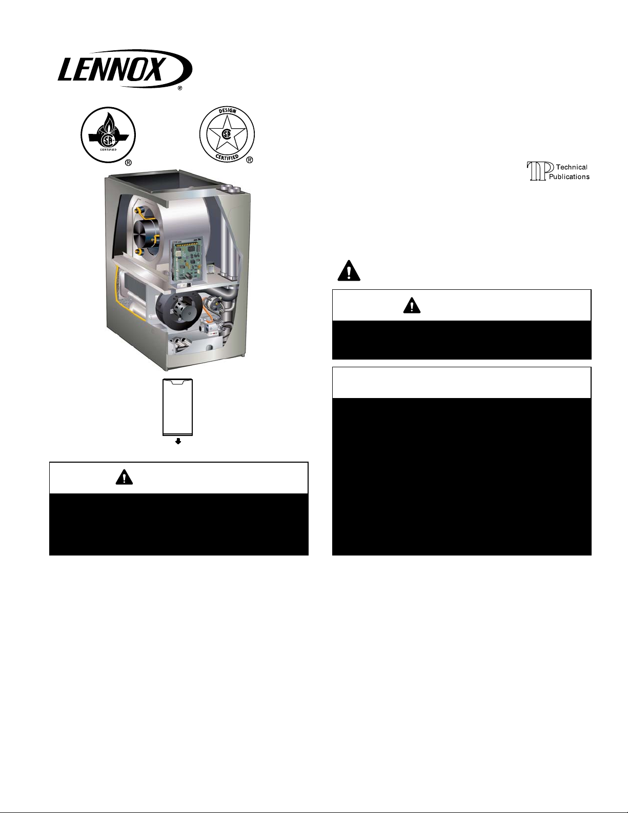
SLP98DFV
DAVE LENNOX SIGNATURE
COLLECTION GAS FURNACE
DOWNFLOW AIR DISCHARGE
506611−01
02/2011
Supersedes 10/2010
THIS MANUAL MUST BE LEFT WITH THE
HOMEOWNER FOR FUTURE REFERENCE
This is a safety alert symbol and should never be ignored.
When you see this symbol on labels or in manuals, be alert
to the potential for personal injury or death.
CAUTION
As with any mechanical equipment, personal injury
can result from contact with sharp sheet metal
edges. Be careful when you handle this equipment.
A thermostat is not included and must be ordered
separately.
The Lennox icomfort Touch thermostat must be
used in communicating applications.
In non−communicating applications, the Lennox
ComfortSense® 7000 thermostat may be used, as
well as other non−communicating thermostats.
In all cases, setup is critical to ensure proper system operation.
Field wiring for both communicating and non−communicating applications is illustrated in diagrams,
which begin on Page 30.
®
Litho U.S.A.
NOTICE
Table of Contents
Unit Dimensions 2. . . . . . . . . . . . . . . . . . . . . . . . . . . . . . . . .
Parts Arrangement 3. . . . . . . . . . . . . . . . . . . . . . . . . . . . . .
SLP98DFV Gas Furnace 4. . . . . . . . . . . . . . . . . . . . . . . . .
Shipping and Packing List 4. . . . . . . . . . . . . . . . . . . . . . . .
Safety Information 4. . . . . . . . . . . . . . . . . . . . . . . . . . . . . . .
Use of Furnace as a Construction Heater 5. . . . . . . . . . .
General 6. . . . . . . . . . . . . . . . . . . . . . . . . . . . . . . . . . . . . . . .
Setting Equipment 6. . . . . . . . . . . . . . . . . . . . . . . . . . . . . . .
Filters 9. . . . . . . . . . . . . . . . . . . . . . . . . . . . . . . . . . . . . . . . .
Duct System 9. . . . . . . . . . . . . . . . . . . . . . . . . . . . . . . . . . .
Pipe and Fittings Specifications 10. . . . . . . . . . . . . . . . . . .
Joint Cementing Procedure 11. . . . . . . . . . . . . . . . . . . . . .
Venting Practices 12. . . . . . . . . . . . . . . . . . . . . . . . . . . . . . .
Vent Piping Guidelines 12. . . . . . . . . . . . . . . . . . . . . . . . . .
Gas Piping 23. . . . . . . . . . . . . . . . . . . . . . . . . . . . . . . . . . . .
02/11
*2P0211*
Page 1
Electrical 27. . . . . . . . . . . . . . . . . . . . . . . . . . . . . . . . . . . . . .
Integrated Control 36. . . . . . . . . . . . . . . . . . . . . . . . . . . . . .
Blower Motor Performance 40. . . . . . . . . . . . . . . . . . . . . . .
Unit Start Up 45. . . . . . . . . . . . . . . . . . . . . . . . . . . . . . . . . . .
Gas Pressure Measurement 46. . . . . . . . . . . . . . . . . . . . .
High Altitude Information 46. . . . . . . . . . . . . . . . . . . . . . . .
Proper Combustions 47. . . . . . . . . . . . . . . . . . . . . . . . . . . .
Other Unit Adjustments 46. . . . . . . . . . . . . . . . . . . . . . . . . .
Heating Sequence of Operation 48. . . . . . . . . . . . . . . . . .
Service 50. . . . . . . . . . . . . . . . . . . . . . . . . . . . . . . . . . . . . . .
Planned Service 52. . . . . . . . . . . . . . . . . . . . . . . . . . . . . . . .
Integrated Control Diagnostic Codes 53. . . . . . . . . . . . . .
Configuring Unit Size Codes 56. . . . . . . . . . . . . . . . . . . . .
Troubleshooting 57. . . . . . . . . . . . . . . . . . . . . . . . . . . . . . . .
Repair Parts List 63. . . . . . . . . . . . . . . . . . . . . . . . . . . . . . .
506611−01
*P506611-01*
Page 2

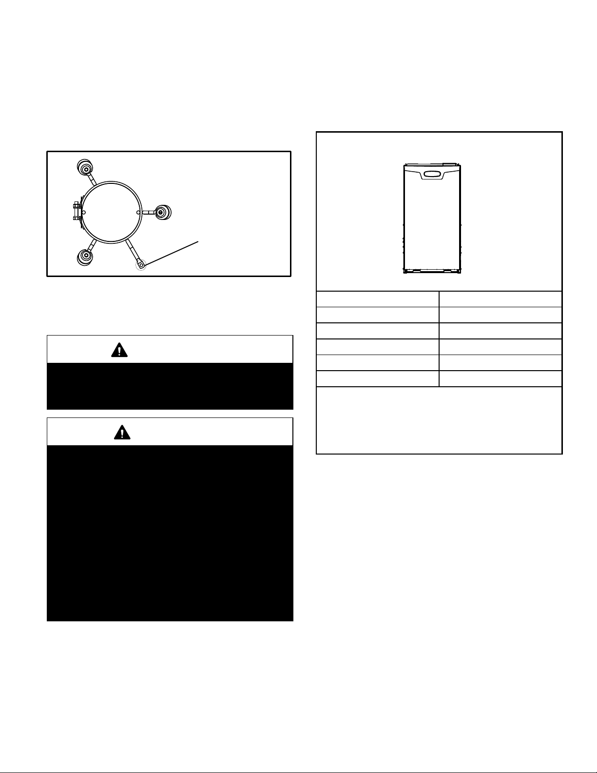
Unit Dimensions − inches (mm)
COMBUSTION
AIR INTAKE
EXHAUST AIR
OUTLET
2−1/16 (52)
5
(127)
2−1/4
(57)
9/16
(14)
RETURN AIR
OPENING
B
9/16
(14)
TOP VIEW
3/4
(19)
AIR
C
A
B
FLOW
Supply
Air
9/16
(14)
3/4
(19)
33
(838)
1−1/2 (38)
Front Panel
2 (51)
Either Side
GAS PIPING INLET
(Either Side)
9−1/8 (232) Right
6−9/16 (167) Left
27−3/4
(7705)
19−7/16
(494)
ELECTRICAL INLET
(Either Side)
CONDENSATE
TRAP CONNECTION
(Either Side)
6−7/16 (163)
Either Side
19−1/4
(489)
9 (229) Right
Either Side
Supply
Air
9/16
(14)
3/4
(19)
FRONT VIEW SIDE VIEW
SLP98DF Model No.
070V36B 17−1/2 446 16−3/8 416 16 406 7−5/8 194
090V36C
090V48C
090V60C
110V60C
A B C D
in. mm in. mm in. mm in. mm
21 533 19−7/8 505 19−1/2 495 9−3/8 238
Page 2
Page 3

Parts Arrangement
CONTROL BOX
(includes variable capacity
integrated control,
transformer, circuit breaker
and door switch)
BLOWER ASSEMBLY
(Variable Speed Blower
Motor Is Hidden)
BLOWER
ACCESS
PANEL
BAG ASSEMBLY
ACCESS PANEL
COMBUSTION AIR INDUCER
GAS VALVE
PRIMARY LIMIT
BURNER BOX ASSEMBLY
FIGURE 1
Page 3
Page 4
SLP98DFV Gas Furnace
Safety Information
The SLP98DFV category IV gas furnace is equipped with
a variable−capacity, variable−speed integrated control.
This control ensures compatibility with the Lennox icomfort Touch thermostat and Harmony III zone control
system, as well as a thermostat which provides humidity
control.
The furnace is equipped for installation in natural gas applications only. A changeover kit may be ordered for LP
applications.
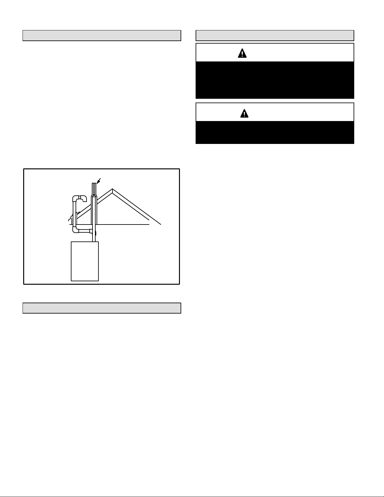
The SLP98DFV must be installed only as a Direct Vent
gas central furnace.
NOTE − In Direct Vent installations, combustion air is taken
from outdoors and flue gases are discharged outdoors. See
figure 2 for applications including roof termination.
DIRECT VENT INSTALLATION
COMBUSTION
AIR INTAKE
OUTSIDE OF
HOUSE
SLP98DFV
EXHAUST OUTLET
FIGURE 2
Shipping and Packing List
Package 1 of 1 contains
1 − Assembled SLP98DFV unit
1 − Bag assembly containing the following:
3 − Wire nuts
1 − Snap bushing
1 − Snap plug
1 − Wire tie
1 − Condensate trap
Check equipment for shipping damage. If you find any
damage, immediately contact the last carrier.
The following items may also be ordered separately:
1 − Thermostat
1 − Natural to LP gas conversion kit
1 − High altitude kit
WARNING
Improper installation, adjustment, alteration, service
or maintenance can cause property damage, personal injury or loss of life. Installation and service must
be performed by a licensed professional installer (or
equivalent), service agency or the gas supplier.
CAUTION
As with any mechanical equipment, personal injury
can result from contact with sharp sheet metal
edges. Be careful when you handle this equipment.
Use only the type of gas approved for use with this furnace.
Refer to unit nameplate.
Building Codes
In the USA, installation of gas furnaces must conform with local building codes. In the absence of local codes, units must
be installed according to the current National Fuel Gas Code
(ANSI-Z223.1/NFPA 54). The National Fuel Gas Code is
available from the following address:
American National Standards Institute, Inc.
11 West 42nd Street
New York, NY 10036
Installation Locations and Clearances
In Canada, installation must conform with current National
Standard of Canada CSA-B149 Natural Gas and Propane
Installation Codes, local plumbing or waste water codes
and other applicable local codes.
This furnace is designed for installation clearances to combustible material as listed on the unit nameplate and in the
table in figure 7. Accessibility and service clearances must
take precedence over fire protection clearances.
For installation in a residential garage, the furnace must
be installed so that the burner(s) and the ignition source
are located no less than 18 inches (457 mm) above the
floor. The furnace must be located or protected to avoid
physical damage by vehicles. When a furnace is installed
in a public garage, hangar, or other building that has a hazardous atmosphere, the furnace must be installed according to recommended good practice requirements and current National Fuel Gas Code or CSA B149 standard.
NOTE − Furnace must be adjusted to obtain a temperature
rise (100% percent capacity) within the range(s) specified on
the unit nameplate. Failure to do so may cause erratic limit
operation and may also result in premature heat exchanger
failure.
This SLP98DFV furnace must be installed so that its electrical components are protected from water.
Page 4
Page 5
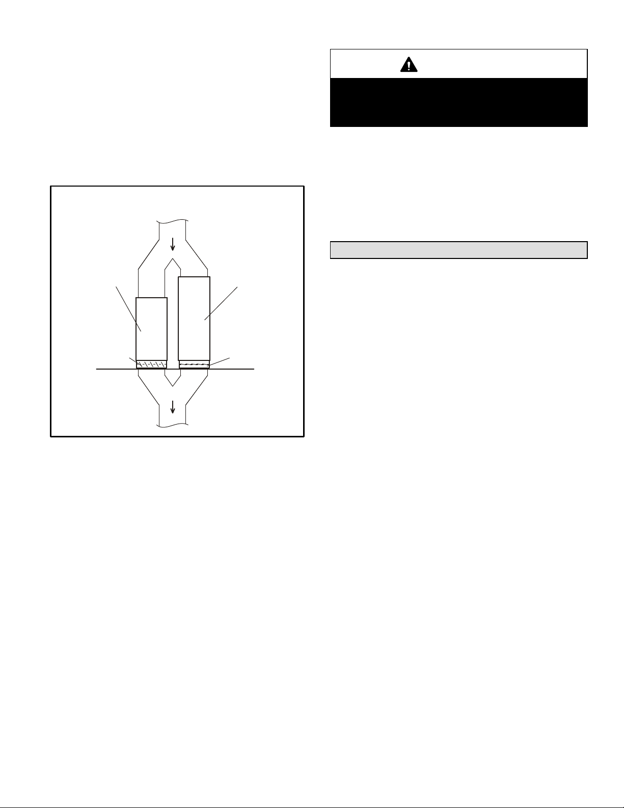
Installed in Combination with a Cooling Coil
When this furnace is used with cooling units, it shall be
installed in parallel with, or on the upstream side of, cooling
units to avoid condensation in the heating compartment.
With a parallel flow arrangement, a damper (or other means
to control the flow of air) must adequately prevent chilled air
from entering the furnace (figure 3). If the damper is manually operated, it must be equipped to prevent operation of either the heating or the cooling unit, unless it is in the full
HEAT or COOL setting.
SLP98DFV INSTALLED PARALLEL
WITH COOLING COIL
GAS UNIT
Dampers
(open during heating
operation only)
AIR HANDLER
Dampers
(open during cooling
operation only)
FIGURE 3
When installed, this furnace must be electrically grounded
according to local codes. In addition, in the United States,
installation must conform with the current National Electric
Code, ANSI/NFPA No. 70. The National Electric Code
(ANSI/NFPA No. 70) is available from the following address:
National Fire Protection Association
1 Battery March Park
Quincy, MA 02269
NOTE − This furnace is designed for a minimum continuous return air temperature of 60°F (16°C) or an intermittent operation down to 55°F (13°C) dry bulb for cases
where a night setback thermostat is used. Return air temperature must not exceed 85°F (29°C) dry bulb.
In Canada, all electrical wiring and grounding for the unit
must be installed according to the current regulations of the
Canadian Electrical Code Part I (CSA Standard C22.1)
and/or local codes.
CAUTION
Do not set thermostat below 60°F (16°C) in heating
mode. Setting thermostat below 60°F (16°C) reduces
the number of heating cycles. Damage to the unit
may occur that is not covered by the warranty.
The SLP98DFV furnace may be installed in alcoves, closets, attics, basements, garages, and utility rooms.
This furnace is not designed for installation in mobile
homes, recreational vehicles, or outdoors.
Never use an open flame to test for gas leaks. Check all
connections using a commercially available soap solution
made specifically for leak detection.
Use of Furnace as Construction Heater
Lennox does not recommend the use of SLP98DFV units
as a construction heater during any phase of construction.
Very low return air temperatures, harmful vapors and operation of the unit with clogged or misplaced filters will damage the unit.
SLP98DFV units may be used for heating of buildings or
structures under construction, if the following conditions
are met:
D The vent system must be permanently installed per
these installation instructions.
D A room thermostat must control the furnace. The use of
fixed jumpers that will provide continuous heating is not
allowed.
D The return air duct must be provided and sealed to the
furnace.
D Return air temperature range between 60°F (16°C) and
80°F (27°C) must be maintained.
D Air filters must be installed in the system and must be
maintained during construction.
D Air filters must be replaced upon construction comple-
tion.
D The input rate and temperature rise must be set per the
furnace rating plate.
D One hundred percent (100%) outdoor air must be pro-
vided for combustion air requirements during construction. Temporary ducting may supply outdoor air to the
furnace. Do not connect duct directly to the furnace.
D The furnace heat exchanger, components, duct system,
air filters and evaporator coils must be thoroughly
cleaned following final construction clean−up.
D All furnace operating conditions (including ignition, in-
put rate, temperature rise and venting) must be verified
according to these installation instructions.
Page 5
Page 6
General
• When the furnace is installed in an unconditioned
space, consider provisions required to prevent freezing
of condensate drain system.
WARNING
Product contains fiberglass wool.
Disturbing the insulation in this product during
installation, maintenance, or repair will expose you
to fiberglass wool. Breathing this may cause lung
cancer. (Fiberglass wool is known to the State of California to cause cancer.)
Fiberglass wool may also cause respiratory, skin,
and eye irritation.
To reduce exposure to this substance or for further
information, consult material safety data sheets
available from address shown below, or contact your
supervisor.
Lennox Industries Inc.
P.O. Box 799900
Dallas, TX 75379−9900
CAUTION
SLP98DFV unit should not be installed in areas normally subject to freezing temperatures.
These instructions are intended as a general guide and do
not supersede local codes in any way. Consult authorities
having jurisdiction before installation.
In addition to the requirements outlined previously, the following general recommendations must be considered
when installing a SLP98DFV furnace:
• Place the furnace as close to the center of the air distribution system as possible. The furnace should also be
located close to the chimney or vent termination point.
• When the furnace is installed in an attic or other insulated space, keep insulation away from the furnace.
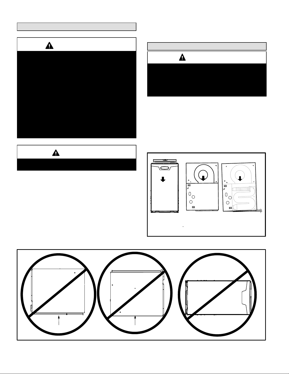
Installation − Setting Equipment
WARNING
Do not install the furnace on its front, back or in the
horizontal position. See figure 5. Do not connect the
return air ducts to the back of the furnace. Doing so
will adversely affect the operation of the safety control devices, which could result in personal injury or
death.
Select a location that allows for the required clearances
that are listed on the unit nameplate. Also consider gas
supply connections, electrical supply, vent connection,
condensate trap and drain connections, and installation
and service clearances [24 inches (610 mm) at unit
front]. The unit must be level from side to side. Unit may
be positioned from level to 1/2" toward the front to aid in
draining. See figure 4.
SETTING EQUIPMENT
AIR FLOW
FRONT VIEW SIDE VIEW
Unit must be level side−to−side. Unit may be positioned
from level to 1/2" toward the front to aid in draining.
AIR FLOW
SIDE VIEW
FIGURE 4
AIR FLOW
1/2"
max.
Front
Horizontal
Back
NOTE − Do not install the furnace on its front, back or in the horizontal position.
FIGURE 5
Page 6
Page 7
NOTE − The 1/2 hp blower motor used in some SLP98DFV
unit is equipped with three flexible legs and one rigid leg.
The rigid leg is equipped with a shipping bolt and a flat white
plastic washer (rather than the rubber mounting grommet
used with a flexible mounting leg). The bolt and washer
must be removed before the furnace is placed into operation. After the bolt and washer have been removed, the
rigid leg will not touch the blower housing.
SLP98DF070V36B and
SL98DF090V036C WITH 1/2 HP
BLOWER MOTOR
RIGID LEG
remove shipping bolt and washer
The unit may be installed three ways in downflow applications: on non−combustible flooring, on combustible flooring
using a base, or on a reverse−flow cooling coil cabinet. Do
not drag the unit across the floor in the downflow position. Floor and flange damage will result.
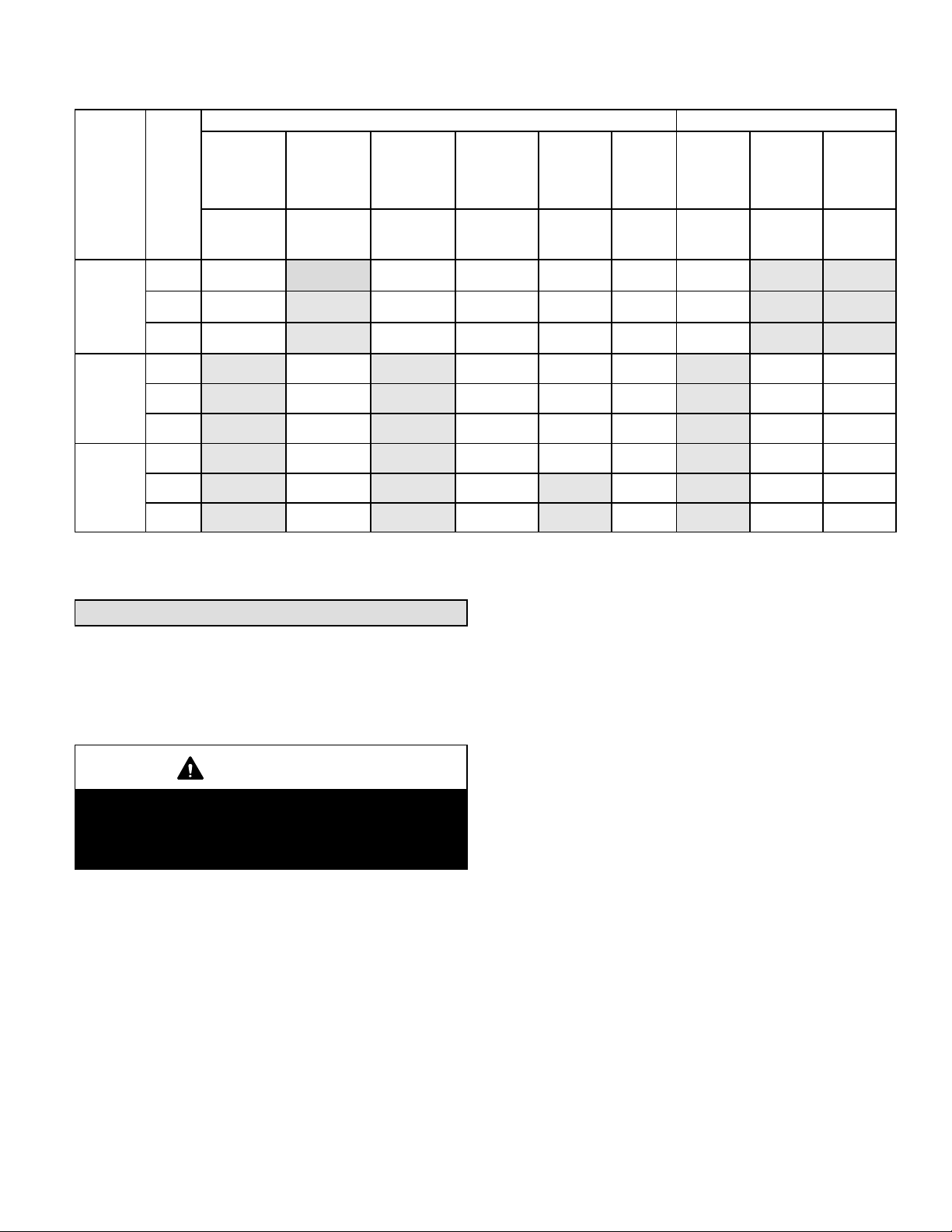
Refer to figure 7 for clearances in downflow applica-
tions.
Downflow Application Installation Clearances
Top
Left Side Right Side
FIGURE 6
Allow for clearances to combustible materials as indicated
on the unit nameplate. Minimum clearances for closet or alcove installations are shown in figure 7.
WARNING
Blower access panel must be securely in place when
blower and burners are operating. Gas fumes, which
could contain carbon monoxide, can be drawn into
living space resulting in personal injury or death.
WARNING
Improper installation of the furnace can result in personal injury or death. Combustion and flue products
must never be allowed to enter the return air system
or air in the living space. Use sheet metal screws and
joint tape to seal return air system to furnace.
In platform installations with furnace return, the furnace should be sealed airtight to the return air plenum. A door must never be used as a portion of the
return air duct system. The base must provide a
stable support and an airtight seal to the furnace. Allow absolutely no sagging, cracks, gaps, etc.
For no reason should return and supply air duct systems ever be connected to or from other heating devices such as a fireplace or stove, etc. Fire, explosion, carbon monoxide poisoning, personal injury
and/or property damage could result.
Bottom
Top 0
*Front 0
Back 0
Sides 0†
Vent 0
Floor NC‡
*Front clearance in alcove installation must be 24 in. (610 mm).
Maintain a minimum of 24 in. (610 mm) for front service access.
†Allow proper clearances to accommodate condensate trap and
vent pipe installation.
‡The furnace may be installed on a combustible wood floor if an optional base is installed between the furnace and the combustible
floor.
FIGURE 7
Installation on Non−Combustible Flooring (Figure 8)
1 − Cut floor opening keeping in mind clearances listed on
unit rating plate. Also keep in mind gas supply connections, electrical supply, flue and air intake connections
and sufficient installation and servicing clearances.
See table 1 for correct floor opening size.
2 − Flange warm air plenum and lower the plenum into the
opening.
3 − Set the unit over the plenum and seal the plenum to
the unit.
4 − Ensure that the seal is adequate.
Page 7
Page 8
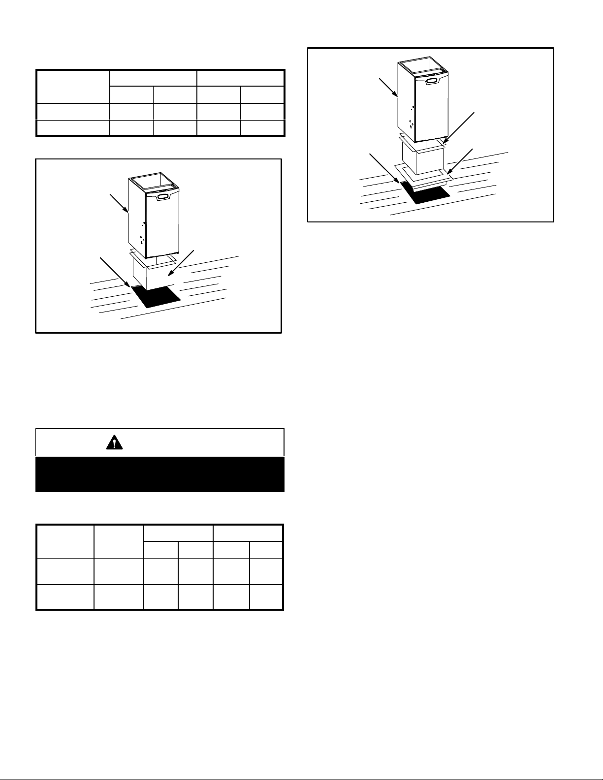
TABLE 1
NON−COMBUSTIBLE FLOOR OPENING SIZE
Cabinet Width
B Cabinet (17.5") 19 − 3/4 502 16 − 5/8 422
C Cabinet (21") 19 − 3/4 502 20−1/8 511
NOTE − Floor opening dimensions listed are 1/4 inch (6 mm) larger than
the unit opening. See dimension drawing on page 2.
SLP98DF UNIT
Front to Rear Side to Side
in. mm in. mm
SLP98DF UNIT
PROPERLY
SIZED FLOOR
OPENING
SUPPLY AIR
PLENUM
COMBUSTIBLE
FLOORING BASE
PROPERLY
SIZED FLOOR
OPENING
SUPPLY AIR
PLENUM
FIGURE 8
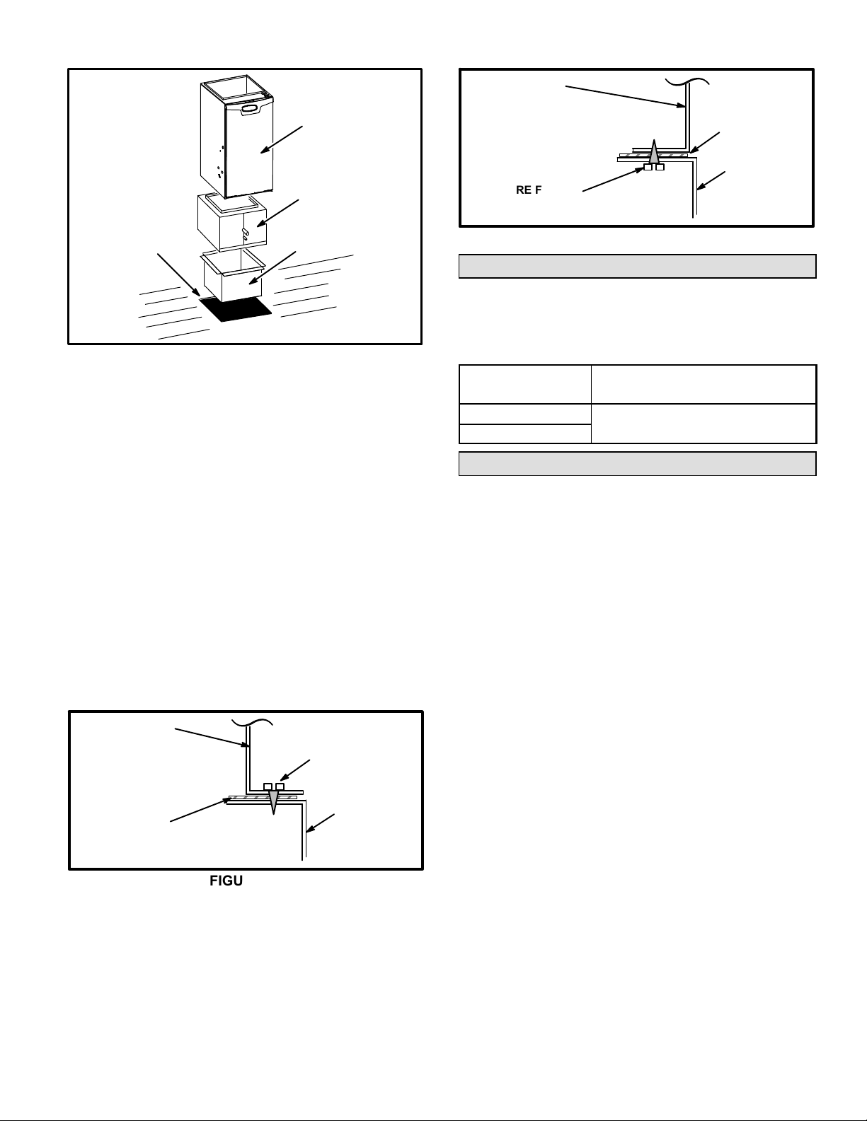
Installation on Combustible Flooring (Figure 9)
1 − When unit is installed on a combustible floor, a down-
flow combustible flooring base must be installed between the furnace and the floor. The base must be ordered separately. See table 2 for opening size to cut in
floor.
CAUTION
The furnace and combustible flooring base shall not
be installed directly on carpeting, tile, or other combustible material other than wood flooring.
TABLE 2
COMBUSTIBLE FLOORING BASE OPENING SIZE
Cabinet
Width
B Cabinet
(17.5")
C Cabinet
(21")
Catalog
Number
11M60
11M61
Front to Rear Side to Side
in. mm in. mm
22 559 18 − 3/4 476
22 559 22 − 3/4 578
FIGURE 9
2 − After opening is cut, set combustible flooring base into
opening.
3 − Check fiberglass strips on combustible flooring base
to make sure they are properly glued and positioned.
4 − Lower supply air plenum into combustible flooring
base until plenum flanges seal against fiberglass
strips.
NOTE − Be careful not to damage fiberglass strips.
Check for a tight seal.
5 − Set the furnace over the plenum.
6 − Ensure that the seal between the furnace and plenum
is adequate.
Installation on Cooling Coil Cabinet (Figure 10)
NOTE − Downflow combustible flooring base is not used.
1 − Refer to reverse−flow coil installation instructions for
correctly sized opening in floor and installation of cabinet.
2 − When cooling cabinet is in place, set and secure the
furnace according to the instructions that are provided
with the cooling coil. Secure the furnace to the cabinet.
3 − Seal the cabinet and check for air leaks.
Page 8
Page 9
PROPERLY
SIZED FLOOR
OPENING
FIGURE 10
SLP98DF UNIT
COOLING COIL
PLENUM
PLENUM
(Field Provided)
SECURE FROM
INSIDE CABINET
Side View
SEALING STRIP
(Field Provided)
CABINET
SIDE PANEL
FIGURE 12
Filters
This unit is not equipped with a filter or rack. A field−provided filter is required for the unit to operate properly. Table
3 lists recommended filter size.
A filter must be in place whenever the unit is operating.
TABLE 3
Furnace
Cabinet Width
Filter Size
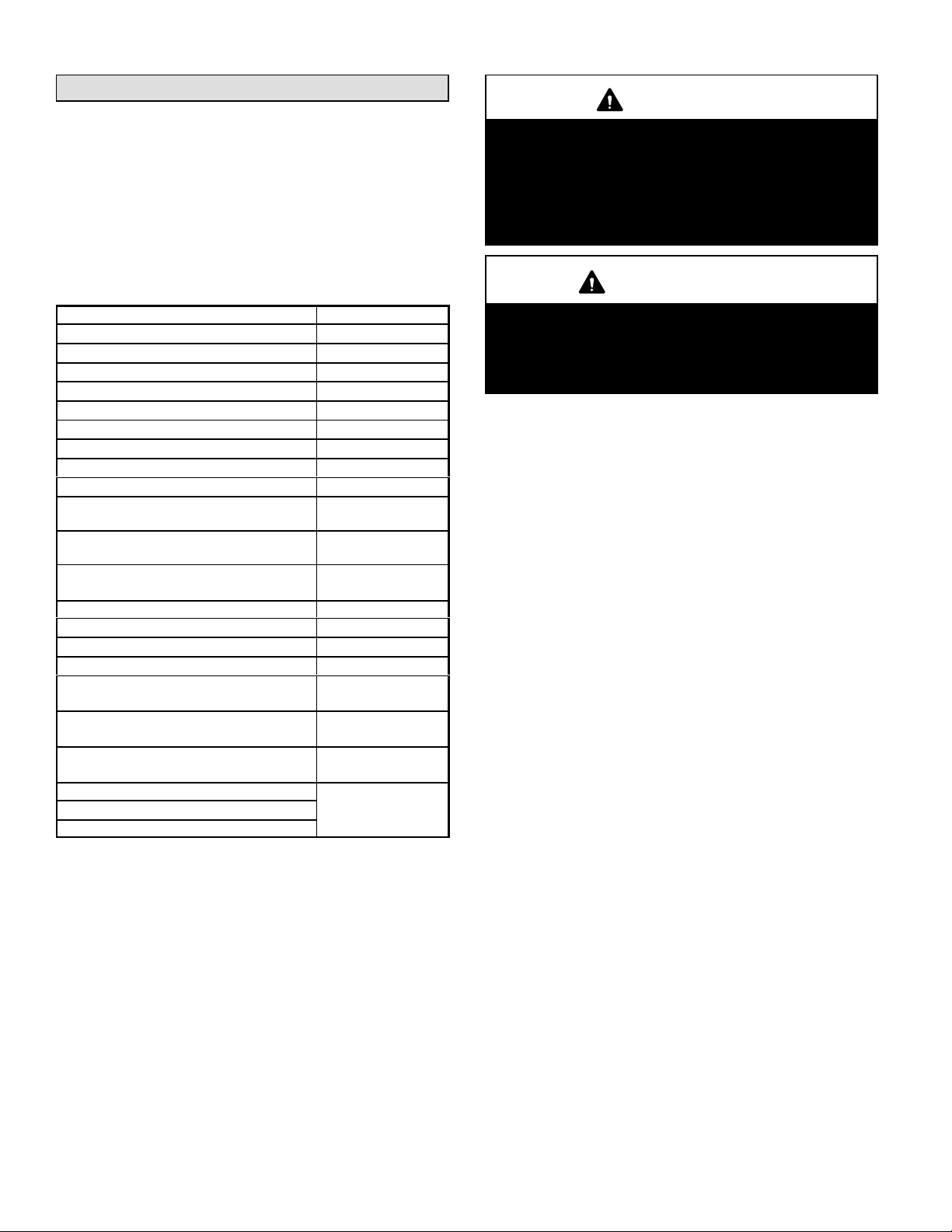
Return Air Opening −− Downflow Units
Return air may be brought in only through the top opening
of a furnace installed in the downflow position. The following steps should be taken when installing plenum:
1 − Bottom edge of plenum should be flanged with a
hemmed edge (See figure 11 or 12).
2 − Sealing strips should be used to ensure an airtight seal
between the cabinet and the plenum.
3 − In all cases, plenum should be secured to top of fur-
nace using sheet metal screws.
4 − Make certain that an adequate seal is made.
PLENUM
(Field Provided)
SEALING STRIP
(Field Provided)
SECURE FROM
OUTSIDE CABINET
CABINET
SIDE PANEL
Side View
FIGURE 11
B Cabinet (17−1/2")
C Cabinet (21−1/2")
16 X 25 X 1 (1)
Duct System
Use industry-approved standards to size and install the
supply and return air duct system. This will result in a quiet
and low-static system that has uniform air distribution.
NOTE − Operation of this furnace in heating mode (indoor
blower operating at selected heating speed) with an external static pressure which exceeds 0.8 inches w.c. may result in erratic limit operation.
Return Air Plenum
Return air must not be drawn from a room where this
furnace, or any other gas−fueled appliance (i.e., water
heater), or carbon monoxide−producing device (i.e.,
wood fireplace) is installed. When return air is drawn
from a room, a negative pressure is created in the room. If
a gas appliance is operating in a room with negative pressure, the flue products can be pulled back down the vent
pipe and into the room. This reverse flow of the flue gas
may result in incomplete combustion and the formation
of carbon monoxide gas. This toxic gas might then be distributed throughout the house by the furnace duct system.
Use fiberglass sealing strips, caulking, or equivalent sealing method between the plenum and the furnace cabinet to
ensure a tight seal. If a filter is installed, size the return air
duct to fit the filter frame.
Page 9
Page 10
Pipe & Fittings Specifications
All pipe, fittings, primer and solvent cement must conform
with American National Standard Institute and the American Society for Testing and Materials (ANSI/ASTM) standards. The solvent shall be free−flowing and contain no
lumps, undissolved particles or any foreign matter that adversely affects the joint strength or chemical resistance of
the cement. The cement shall show no gelation, stratification, or separation that cannot be removed by stirring. Refer to table 4 for approved piping and fitting materials.
PIPING AND FITTINGS SPECIFICATIONS
Schedule 40 PVC (Pipe) D1785
Schedule 40 PVC (Cellular Core Pipe) F891
Schedule 40 PVC (Fittings) D2466
Schedule 40 CPVC (Pipe) F441
Schedule 40 CPVC (Fittings) F438
SDR−21 PVC or SDR−26 PVC (Pipe) D2241
SDR−21 CPVC or SDR−26 CPVC (Pipe) F442
Schedule 40 ABS Cellular Core DWV (Pipe) F628
Schedule 40 ABS (Pipe) D1527
Schedule 40 ABS (Fittings) D2468
ABS−DWV (Drain Waste & Vent)
(Pipe & Fittings)
PVC−DWV (Drain Waste & Vent)
Pipe & Fittings)
PRIMER & SOLVENT CEMENT
PVC & CPVC Primer F656
PVC Solvent Cement D2564
CPVC Solvent Cement F493
ABS Solvent Cement D2235
PVC/CPVC/ABS All Purpose Cement For
Fittings & Pipe of the same material
ABS to PVC or CPVC Transition Solvent
Cement
CANADIAN PIPE, FITTINGS &
SOLVENT CEMENT
PVC & CPVC Pipe and Fittings
PVC & CPVC Solvent Cement
ABS to PVC or CPVC Transition Cement
TABLE 4
D2661
D2665
ASTM
SPECIFICATION
D2564, D2235, F493
D3138
MARKING
ULCS636
CAUTION
Solvent cements for plastic pipe are flammable liquids and should be kept away from all sources of
ignition. Do not use excessive amounts of solvent
cement when making joints. Good ventilation should
be maintained to reduce fire hazard and to minimize
breathing of solvent vapors. Avoid contact of cement
with skin and eyes.
IMPORTANT
SLP98DFV exhaust and intake connections are
made of PVC. Use PVC primer and solvent cement
when using PVC vent pipe. When using ABS vent
pipe, use transitional solvent cement to make connections to the PVC fittings in the unit.
Use PVC primer and solvent cement or ABS solvent cement
meeting ASTM specifications, refer to Table 4. As an alternate, use all purpose cement, to bond ABS, PVC, or CPVC
pipe when using fittings and pipe made of the same materials. Use transition solvent cement when bonding ABS to either PVC or CPVC.
Low temperature solvent cement is recommended. Metal or
plastic strapping may be used for vent pipe hangers. Uniformly apply a liberal coat of PVC primer for PVC
Canadian Applications Only − Pipe, fittings, primer
and solvent cement used to vent (exhaust) this appliance must be certified to ULC S636 and supplied by a
single manufacturer as part of an approved vent (exhaust) system. In addition, the first three feet of vent
pipe from the furnace flue collar must be accessible for
inspection.
Table 5 lists the available exhaust termination kits.
Page 10
Page 11
SLP98DF
UNIT
OUTDOOR TERMINATION KITS USAGE
TABLE 5
STANDARD CONCENTRIC
Outdoor
VENT
PIPE
DIA.
(in.)
2 YES YES YES* YES YES YES
Exhaust
Accelerator
(Dia. X
Length)
1−1/2" X 12" 2" X 12"
Outdoor
Exhaust
Accelerator
(Dia. X
Length)
2" Wall Plate
Kit
22G44
or 30G28
3" Wall Plate
Kit
44J40
or 81J20
2" Wall
Ring Kit
15F74 51W11**
FlushMount
Kit
Concentric
44W92
1−1/2"
Kit
71M80
or
2"
Concentric
Kit
69M29
or
44W92
3"
Concentric
Kit
60L46
or 44W93
070
090
110
*Requires field−provided and installed 1−1/2" exhaust accelerator.
** Kit 51W11 includes h a 1−1/2" accelerator which must be used for all SLP98DFV−070 and −090 installations.
Termination kits 44W92, 44W93, 30G28 and 81J20 approved for use in Canadian installations.
The 44W92 concentric kit includes a 1−1/2" accelerator which must be installed on the exhaust outlet when this kit is used with the SL98DF070V36B furnaces.
Joint Cementing Procedure
All cementing of joints should be done according to the
specifications outlined in ASTM D 2855.
NOTE − A sheet metal screw may be used to secure
the intake pipe to the connector, if desired. Use a drill
or self tapping screw to make a pilot hole.
2−1/2 YES YES YES* YES YES YES
3 YES YES YES* YES YES YES
2 YES YES YES YES YES YES
2−1/2 YES YES YES YES YES YES
3 YES YES YES YES YES YES
2 YES YES YES YES YES YES
2−1/2 YES YES YES YES YES
3 YES YES YES YES YES
5 − Uniformly apply a liberal coat of PVC primer for PVC or
use a clean dry cloth for ABS to clean inside socket
surface of fitting and male end of pipe to depth of fitting
socket.
6 − Promptly apply solvent cement to end of pipe and in-
side socket surface of fitting. Cement should be applied lightly but uniformly to inside of socket. Take
care to keep excess cement out of socket. Apply second coat to end of pipe.
DANGER
DANGER OF EXPLOSION!
Fumes from PVC glue may ignite during system
check. Allow fumes to dissipate for at least 5 minutes
before placing unit into operation.
NOTE − Time is critical at this stage. Do not allow primer to dry before applying cement.
7 − Immediately after applying last coat of cement to pipe,
and while both inside socket surface and end of pipe
are wet with cement, forcefully insert end of pipe into
socket until it bottoms out. Turn PVC pipe 1/4 turn during assembly (but not after pipe is fully inserted) to dis-
1 − Measure and cut vent pipe to desired length.
2 − Debur and chamfer end of pipe, removing any ridges
or rough edges. If end is not chamfered, edge of pipe
may remove cement from fitting socket and result in a
leaking joint.
3 − Clean and dry surfaces to be joined.
NOTE − Check the inside of vent pipe thoroughly for
any obstruction that may alter furnace operation.
4 − Test fit joint and mark depth of fitting on outside of pipe.
tribute cement evenly. DO NOT turn ABS or cellular
core pipe.
NOTE − Assembly should be completed within 20 seconds after last application of cement. Hammer blows
should not be used when inserting pipe.
8 − After assembly, wipe excess cement from pipe at end
of fitting socket. A properly made joint will show a
bead around its entire perimeter. Any gaps may indicate a defective assembly due to insufficient solvent.
9 − Handle joints carefully until completely set.
Page 11
Page 12
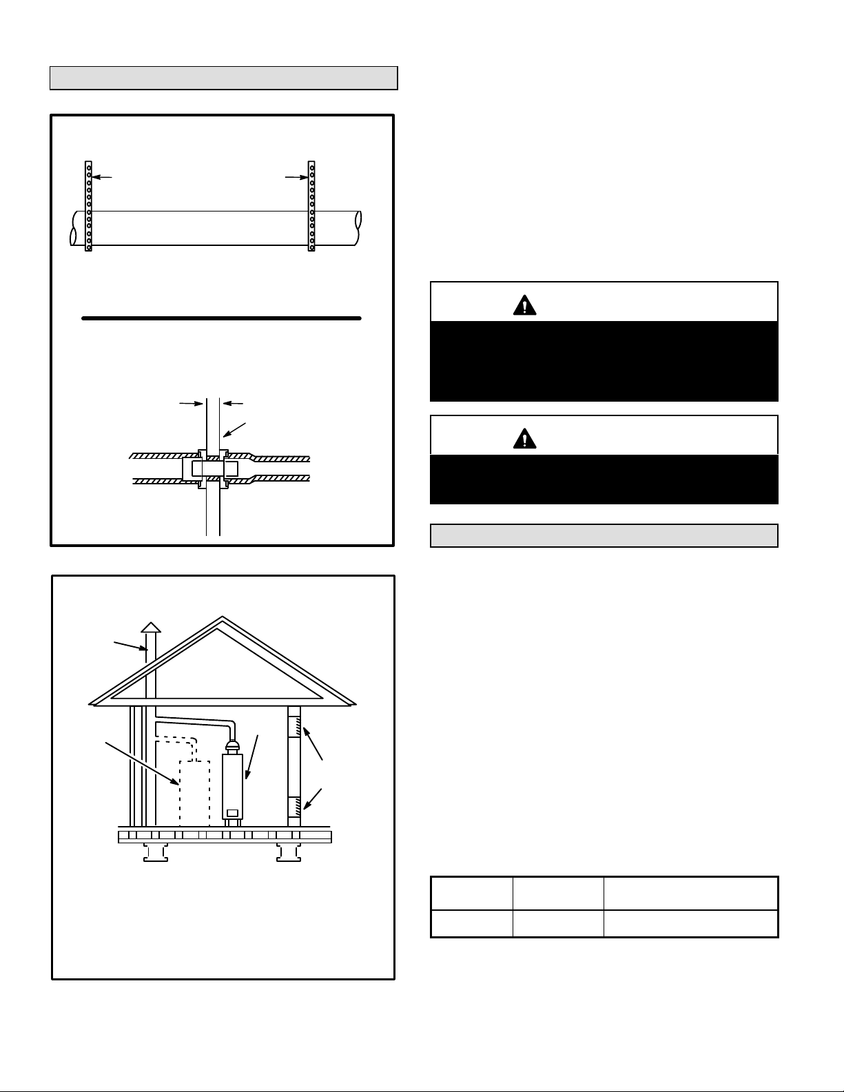
Venting Practices
Piping Suspension Guidelines
SCHEDULE 40 PVC −−
Support every 5 feet.
all other pipe* −−
Support every 3 feet.
* See table 4 for allowable pipe.
NOTE − Isolate piping at the point where it exits the outside wall or
roof in order to prevent transmission of vibration to the structure.
Wall Thickness Guidelines
24" maximum
3/4" minimum
1 − In areas where piping penetrates joists or interior
walls, hole must be large enough to allow clearance on
all sides of pipe through center of hole using a hanger.
2 − When furnace is installed in a residence where unit is
shut down for an extended period of time, such as a
vacation home, make provisions for draining condensate collection trap and lines.
Exhaust Piping (Figure 16)
Route piping to outside of structure. Continue with installation following instructions given in piping termination section.
CAUTION
Do not discharge exhaust into an existing stack or
stack that also serves another gas appliance. If vertical discharge through an existing unused stack is required, insert PVC pipe inside the stack until the end
is even with the top or outlet end of the metal stack.
inside outside
Wall
FIGURE 13
REPLACING FURNACE THAT WAS PART OF A
CHIMNEY
OR GAS
VENT
(Check sizing
for water
heater only)
FURNACE
(Replaced
by SLP98)
If an SLP98 furnace replaces a furnace which was commonly vented with another gas appliance, the size of the
existing vent pipe for that gas appliance must be checked.
Without the heat of the original furnace flue products, the
existing vent pipe is probably oversized for the single water
heater or other appliance. The vent should be checked for
proper draw with the remaining appliance.
COMMON VENT SYSTEM
WATER
HEATER
OPENINGS
(To Adjacent
Room)
FIGURE 14
CAUTION
The exhaust vent pipe operates under positive pressure and must be completely sealed to prevent leakage of combustion products into the living space.
Vent Piping Guidelines
The SLP98DFV is installed only as a Direct Vent gas
central furnace.
NOTE − In Direct Vent installations, combustion air is taken
from outdoors and flue gases are discharged outdoors.
Intake and exhaust pipe sizing −− Size pipe according to
tables 6 and 7. Table 6 lists the minimum vent pipe lengths
permitted. Table 7 lists the maximum pipe lengths per-
mitted.
Regardless of the diameter of pipe used, the standard roof
and wall terminations described in section Exhaust Piping
Terminations should be used. Exhaust vent termination
pipe is sized to optimize the velocity of the exhaust gas as
it exits the termination. Refer to table 9.
In some applications which permit the use of several different sizes of vent pipe, a combination vent pipe may be
used. Contact Lennox’ Application Department for assistance in sizing vent pipe in these applications.
15 ft.*
TABLE 6
EXAMPLE
5 ft. plus 2 elbows of 2", 2−1/2"
or 3" diameter pipe
MINIMUM VENT PIPE LENGTHS
SLP98DF
MODEL
070, 090, 110
*Any approved termination may be added to the minimum equivalent length
listed.
MIN. EQUIV.
VENT LENGTH
NOTE − It is acceptable to use any pipe size which fits within
the guidelines allowed in table 7.
Page 12
Page 13
NOTE − The exhaust collar on all models is sized to accommodate 2" Schedule 40 vent pipe. Contact the Application Department for more information concerning
sizing of vent systems which include multiple pipe sizes.
NOTE − All horizontal runs of exhaust pipe must slope back
toward unit. A minimum of 1/4" (6mm) drop for each 12"
(305mm) of horizontal run is mandatory for drainage.
NOTE − Exhaust pipe MUST be glued to furnace exhaust
fittings.
NOTE − Exhaust piping should be checked carefully to
make sure there are no sags or low spots.
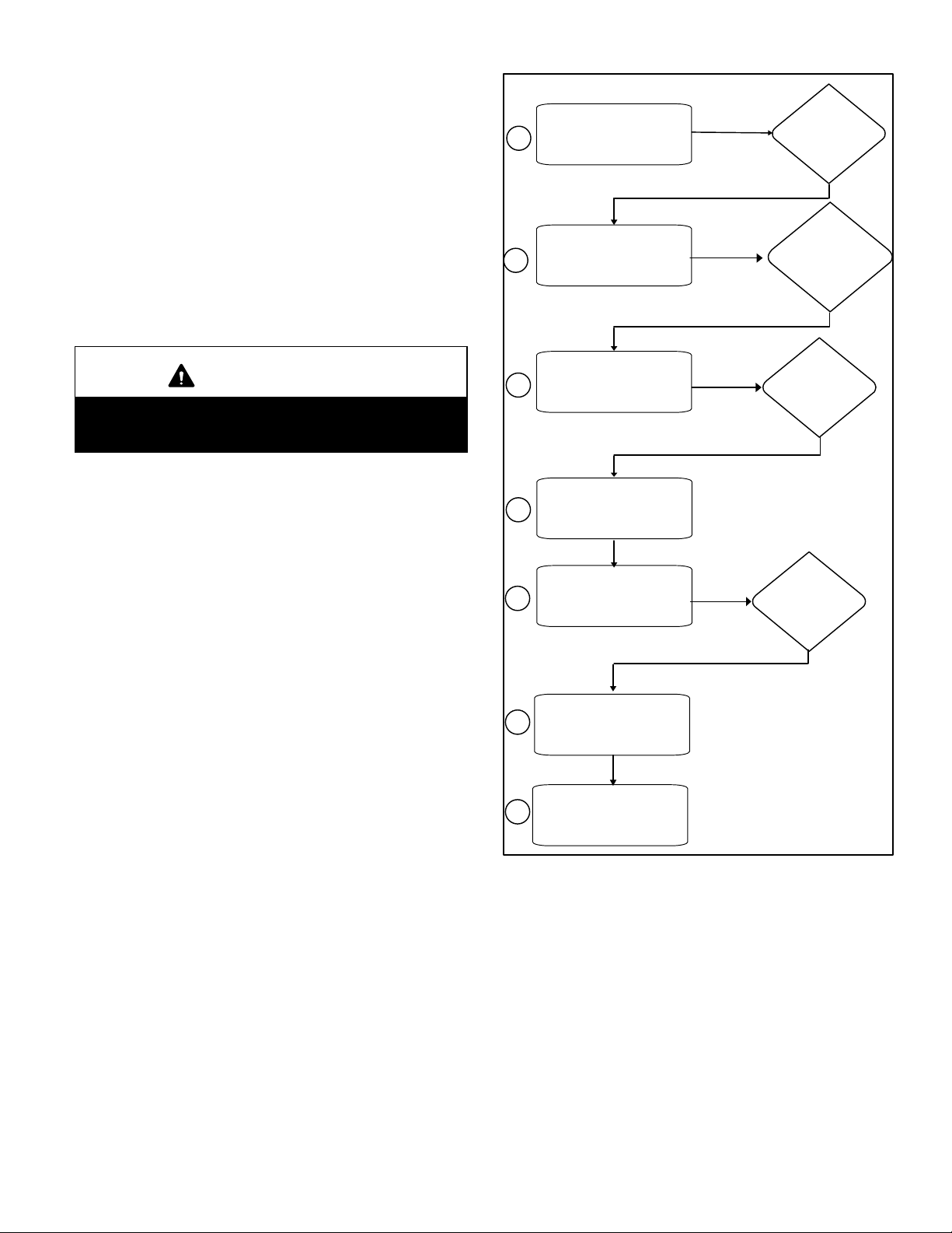
Use the following steps to correctly size vent pipe diameter.
Furnace
1
2
Capacity?
Which termination?
070, 090, 110
btuh
Standard or
Concentric?
See table 5
IMPORTANT
Do not use screens or perforated metal in exhaust or
intake terminations. Doing so will cause freeze−ups
and may block the terminations.
3
4
5
6
7
Which needs
most elbows?
How many?
Desired pipe size?
What is the altitude?
Use table 7 to find
max intake or
exhaust pipe length.
Intake or
exhaust?
2", 2−1/2", 3"
Page 13
FIGURE 15
Page 14
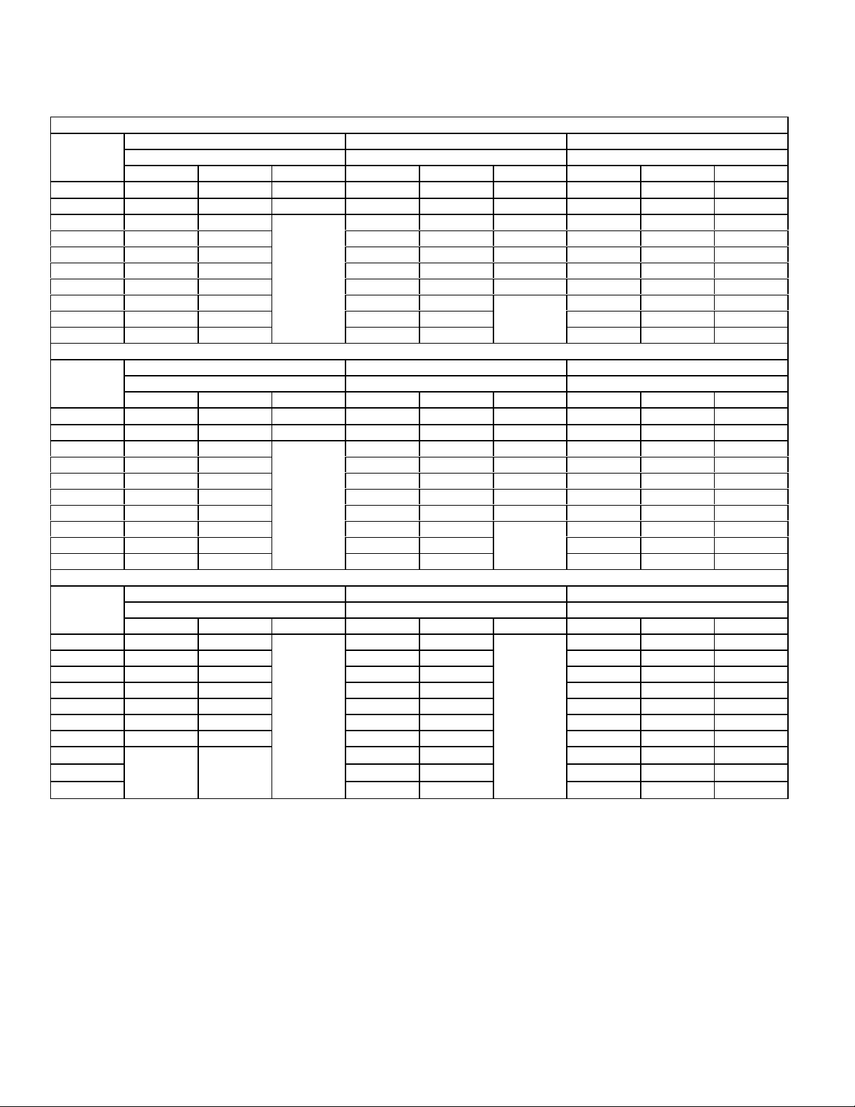
Maximum Allowable Intake or Exhaust Vent Length in Feet
TABLE 7
*Size intake and exhaust pipe length separately. Values in table are for Intake OR Exhaust, not combined total. Both Intake and Exhaust must be same pipe size.
Standard Termination at Elevation 0 − 4500’
Number Of
90° Elbows
Used
1 91 69 14 140 93 43 162 143 11 8
2 86 64 9 135 88 38 157 138 11 3
3 81 59
4 76 54 125 78 28 147 128 103
5 71 49 120 73 23 142 123 98
6 66 44 115 68 18 137 118 93
7 61 39 110 63 13 132 113 88
8 56 34 105 58
9 51 29 100 53 122 103 78
10 46 24 95 48 117 98 73
Number Of
90° Elbows
Used
1 66 69 14 115 93 43 137 143 11 8
2 61 64 9 110 88 38 132 138 11 3
3 56 59
4 51 54 100 78 28 122 128 103
5 46 49 95 73 23 117 123 98
6 41 44 90 68 18 112 118 93
7 36 39 85 63 13 107 113 88
8 31 34 80 58
9 26 29 75 53 97 103 78
10 21 24 70 48 92 98 73
Number Of
90° Elbows
Used
1 41 44
2 36 39 85 63 107 113 88
3 31 34 80 58 102 108 83
4 26 29 75 53 97 103 78
5 21 24 70 48 92 98 73
6 16 19 65 43 87 93 68
7 11 14 60 38 82 88 63
8
9 50 28 72 78 53
10 45 23 67 73 48
070 090 110 070 090 110 070 090 110
070 090 11 0 070 090 110 070 090 110
070 090 11 0 070 090 110 070 090 110
n/a
2" Pipe 2−1/2" Pipe 3" Pipe
Model Model Model
130 83 33 152 133 108
n/a
127 108 83
n/a
Standard Termination Elevation 4501’ − 7500’
2" Pipe 2−1/2" Pipe 3" Pipe
Model Model Model
105 83 33 127 133 108
n/a
102 108 83
n/a
Standard Terminatiuon at Elevation 7501’ − 10,000’’
2" Pipe 2−1/2" Pipe 3" Pipe
Model Model Model
n/a
n/a
90 68
n/a
55 33 77 83 58
112 11 8 93
NOTE − Table 7 continued on next page with concentric terminations.
Page 14
Page 15
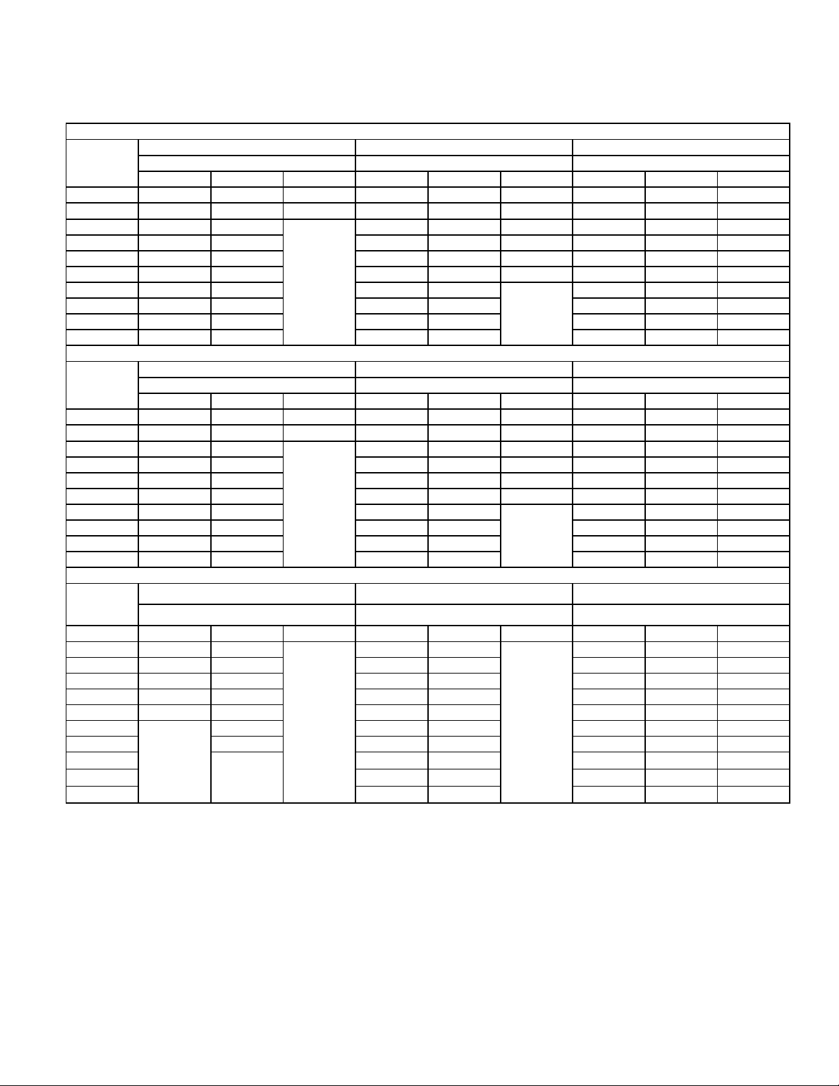
TABLE 7
Maximum Allowable Intake or Exhaust Vent Length in Feet
*Size intake and exhaust pipe length separately. Values in table are for Intake OR Exhaust, not combined total. Both Intake and Exhaust must be same pipe size.
Concentric Termination at Elevation 0 − 4500’
Number Of
90° Elbows
Used
1 83 67 12 130 89 39 146 139 11 4
2 78 62 7 125 84 34 141 134 109
3 73 57
4 68 52 115 74 24 131 124 99
5 63 47 110 69 19 126 119 94
6 58 42 105 64 14 121 114 89
7 53 37 100 59
8 48 32 95 54 111 104 79
9 43 27 90 49 106 99 74
10 38 22 85 44 101 94 69
Number Of
90° Elbows
Used
1 58 67 12 105 89 39 121 114 11 4
2 53 62 7 100 84 34 11 6 109 109
3 48 57
4 43 52 90 74 24 106 99 99
5 38 47 85 69 19 101 94 94
6 33 42 80 64 14 96 89 89
7 28 37 75 59
8 23 32 70 54 86 79 79
9 18 27 65 49 81 74 74
10 13 22 60 44 76 69 69
Number Of
90° Elbows
Used
1 33 42
2 28 37 75 59 91 109 84
3 23 32 70 54 86 104 79
4 18 27 65 49 81 99 74
5 13 22 60 44 76 94 69
6
7 12 50 34 66 84 59
8
9 40 24 56 74 49
10 35 19 51 69 44
070 090 11 0 070 090 110 070 090 11 0
070 090 11 0 070 090 110 070 090 11 0
070 090 11 0 070 090 110 070 090 110
n/a
2" Pipe 2−1/2" Pipe 3" Pipe
Model Model Model
120 79 29 136 129 104
n/a
n/a
Concentric Termination Elevation 4501’ − 7500’
2" Pipe 2−1/2" Pipe 3" Pipe
Model Model Model
95 79 29 111 104 104
n/a
n/a
Concentric Terminatioin at Elevation 7501’ − 10,000’’
2" Pipe 2−1/2" Pipe 3" Pipe
Model Model Model
80 64
17 55 39 71 89 64
n/a
n/a
45 29 61 79 54
n/a
116 109 84
91 84 84
96 11 4 89
Page 15
Page 16
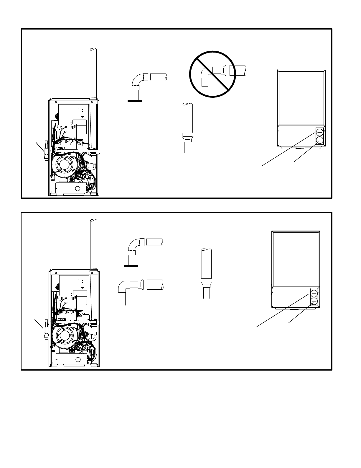
TYPICAL EXHAUST PIPE CONNECTIONS AND CONDENSATE TRAP INSTALLATION
TRAP
2”
2”
2”
DO NOT transition
from smaller to larger
pipe size in horizontal
3”
TRANSITION
*2“
Use only the factory−supplied
trap. Trap can be installed on
either side of cabinet within 5 ft.
of the furnace.
* When transitioning up in pipe size, use the shortest length of 2” PVC pipe possible.
NOTE − Exhaust pipe and intake pipe must be the same diameter.
runs of exhaust pipe.
Air Intake
FIGURE 16
TYPICAL AIR INTAKE PIPE CONNECTIONS
2”
2”
2”
Exhaust
TOP VIEW
TRAP
TRANSITION
*2”
*2”
Use only the factory−supplied
trap. Trap can be installed on
either side of cabinet within 5 ft.
of the furnace.
* When transitioning up in pipe size, use the shortest length of 2” PVC pipe possible.
NOTE − Intake pipe and exhaust pipe must be the same diameter.
3”
3”
TRANSITION
*2”
Air Intake
FIGURE 17
Exhaust
TOP VIEW
Page 16
Page 17
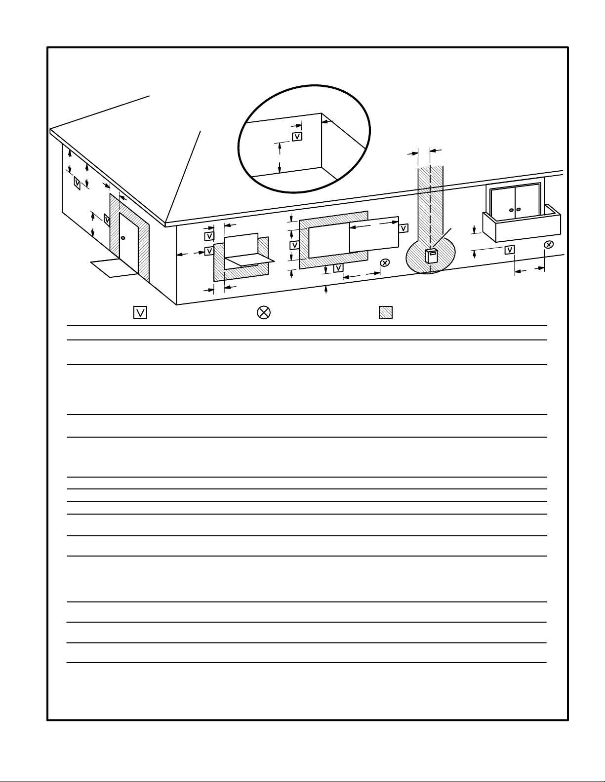
VENT TERMINATION CLEARANCES
FOR DIRECT VENT INSTALLATIONS IN THE USA AND CANADA
INSIDE CORNER
DETAIL
G
D
A
E
B
L
C
Fixed
F
Closed
Operable
B
B
B
VENT TERMINAL
AIR SUPPLY INLET
US Installations
A =
B =
Clearance above grade, veranda,
porch, deck or balcony
Clearance to window or
door that may be opened
12 inches (305mm) or 12 in. 305mm)
above average snow accumulation.
6 inches (152mm) for appliances <10,000
Btuh (3kw), 9 inches (mm) for appliances
> 10,000 Btuh (3kw) and <50,000 Btuh
(15 kw), 12 inches (305mm) for ap-
pliances > 50,000 Btuh (15kw)
C =
Clearance to permanently
closed window
D =
Vertical clearance to ventilated soffit
located above the terminal within a
* Equal to or greater than soffit depth
horizontal distance of 2 feet (mm)
from the center line of the terminal
E =
F =
G =
H =
Clearance to unventilated soffit
Clearance to outside corner
Clearance to inside corner
Clearance to each side of center line ex-
tended above meter / regulator assembly
I =
Clearance to service regulator
vent outlet
J =
Clearance to non−mechanical air
supply inlet to building or the com-
bustion air inlet to any other ap-
pliance
* Equal to or greater than soffit depth * Equal to or greater than soffit depth
* No minimum to outside corner
3 feet (.9m) within a height 15 feet (4.5m)
above the meter / regulator assembly
*
3 feet (.9m)
6 inches (152mm) for appliances <10,000
Btuh (3kw), 9 inches (mm) for appliances
> 10,000 Btuh (3kw) and <50,000 Btuh
(15 kw), 12 inches (305mm) for ap-
pliances > 50,000 Btuh (15kw)
K =
L =
M =
1
2
A vent shall not terminate directly above a sidewalk or paved driveway that is located
between two single family dwellings and serves both dwellings.
Permitted only if veranda, porch, deck or balcony is fully open on a minimum of two
sides beneath the floor. Lennox recommends avoiding this location if possible.
Clearance to mechanical air sup-
ply inlet
Clearance above paved sidewalk or
paved driveway located on public property
Clearance under veranda, porch,
deck or balcony
In accordance with the current ANSI Z223.1/NFPA 54 Natural Fuel Gas Code
In accordance with the current CSA B149.1, Natural Gas and Propane Installation Code
3 feet (.9m) above if within 10 feet
(3m) horizontally
* 7 feet (2.1m)
*12 inches (305mm)
FIGURE 18
H
Operable
A
Fixed
Closed
J
B
I
M
AREA WHERE TERMINAL
IS NOT PERMITTED
1
Canadian Installations
12 inches (305mm) or 12 in. 305mm)
above average snow accumulation.
6 inches (152mm) for appliances <10,000
Btuh (3kw), 12 inches (305mm) for
appliances > 10,000 Btuh (3kw) and
<100,000 Btuh (30kw), 36 inches (.9m)
for appliances > 100,000 Btuh (30kw)
* 12"
* 12"
* Equal to or greater than soffit depth* Equal to or greater than soffit depth
* No minimum to outside corner
*
*
3 feet (.9m) within a height 15 feet (4.5m)
above the meter / regulator assembly
3 feet (.9m)
6 inches (152mm) for appliances <10,000
Btuh (3kw), 12 inches (305mm) for
appliances > 10,000 Btuh (3kw) and
<100,000 Btuh (30kw), 36 inches (.9m)
for appliances > 100,000 Btuh (30kw)
6 feet (1.8m)
7 feet (2.1m)
12 inches (305mm)
*For clearances not specified in ANSI Z223.1/NFPA 54 or CSA B149.1, clearance
will be in accordance with local installation codes and the requirements of the gas
supplier and these installation instructions."
K
2
Page 17
Page 18
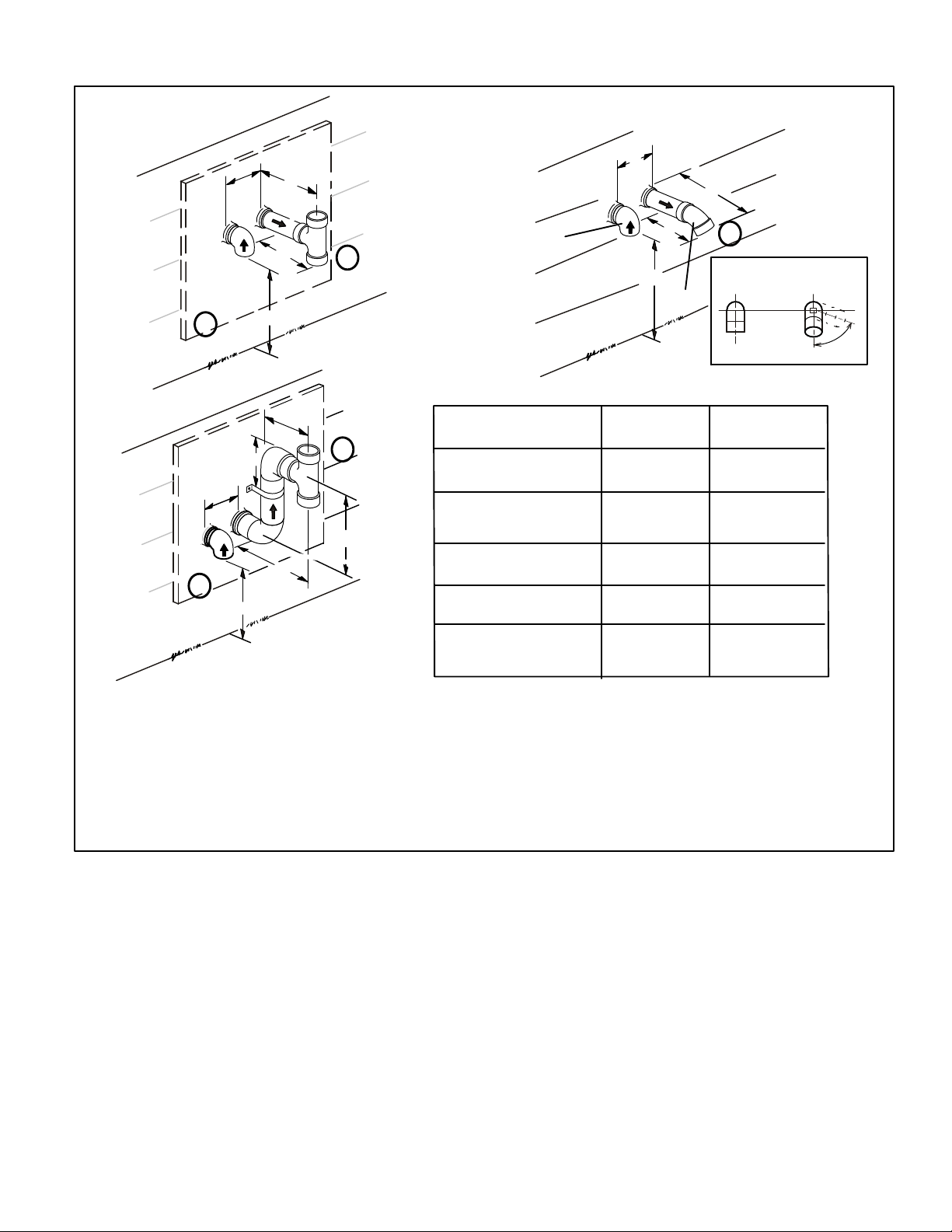
Details of Intake and Exhaust Piping Terminations for
Direct Vent Installations
NOTE − In Direct Vent installations, combustion air is taken from outdoors and flue gases are discharged to outdoors.
NOTE − Flue gas may be slightly acidic and may adversely
affect some building materials. If any vent termination is
used and the flue gasses may impinge on the building material, a corrosion−resistant shield (minimum 24 inches
square) should be used to protect the wall surface. If the
optional tee is used, the protective shield is recommended.
The shield should be constructed using wood, plastic,
sheet metal or other suitable material. All seams, joints,
cracks, etc. in the affected area should be sealed using an
appropriate sealant. See figure 21.
Intake and exhaust pipes may be routed either horizontally
through an outside wall or vertically through the roof. In attic
or closet installations, vertical termination through the roof
is preferred. Figures 19 through 28 show typical terminations.
1 − Exhaust and intake exits must be in same pressure
zone. Do not exit one through the roof and one on the
side. Also, do not exit the intake on one side and the
exhaust on another side of the house or structure.
2 − Intake and exhaust pipes should be placed as close
together as possible at termination end (refer to illustrations). Maximum separation is 3" (76mm) on roof
terminations and 6" (152mm) on side wall terminations.
3 − On roof terminations, the intake piping should termi-
nate straight down using two 90° elbows (See figure
19).
4 − Exhaust piping must terminate straight out or up as
shown. A reducer may be required on the exhaust piping at the point where it exits the structure to improve
the velocity of exhaust away from the intake piping.
See table 9.
NOTE − Care must be taken to avoid recirculation of
exhaust back into intake pipe.
Inches(mm)
8" (203mm) MIN
12" (305mm) ABOVE
AVERAGE SNOW
ACCUMULATION
3" (76mm) OR
2" (51mm) PVC
PROVIDE SUPPORT
FOR INTAKE AND
EXHAUST LINES
DIRECT VENT ROOF TERMINATION KIT
3"(76mm) MAX.
(15F75 or 44J41)
SIZE TERMINATION
PIPE PER TABLE 9.
UNCONDITIONED
ATTIC SPACE
1/2" (13mm) FOAM
INSULATION IN
UNCONDITIONED
SPACE
FIGURE 19
FIELD−SUPPLIED WALL TERMINATION OR
(15F74) WALL RING TERMINATION KIT
NOTE − FIELD−PROVIDED
REDUCER MAY BE
REQUIRED TO ADAPT
LARGER VENT PIPE SIZE
TO TERMINATION.
1/2" (13mm) ARMAFLEX
INSULATION IN
UNCONDITIONED SPACE
SIZE TERMINATION
PER TABLE 9
D
B
C
A
1/2" (13mm) ARMAFLEX INSULATION
IN UNCONDITIONED SPACE
STRAIGHT
APPPLICATION
D
* WALL
SUPPORT
E
B
A
C
EXTENDED
APPLICATION
See venting table 7 for maximum venting lengths with this
arrangement.
* Use wall support every 24" (610 mm). Use two wall supports if
extension is greater than 24" (610 mm) but less than 48" (1219
mm). NOTE − One wall support must be 6" (152 mm) from top
of each pipe (intake and exhaust).
A−Minimum clearance
above grade or average
snow accumulation
B−Maximum horizontal
separation between
intake and exhaust
C−Minimum from
end of exhaust to
inlet of intake
D−Maximum exhaust
pipe length
E−Maximum wall support
distance from top of each
pipe (intake/exhaust)
2" (51mm)
Vent Pipe
12" (508MM) 12" (508MM)
6" (152MM) 6" (152MM)
8" (203MM) 8" (203MM)
12" (305MM) 20" (508MM)
6" (152MM) 6" (152MM)
3" (76mm)
Vent Pipe
FIGURE 20
Page 18
Page 19
B
D
B
D
Intake
C
1
C
A
Exhaust
2
A
3
Front View of
Intake and Exhaust
Intake
Exhaust
TABLE 8
D
E
1
B
12"
C
2
A
A− Clearance above
grade or average snow
accumulation
B−Horizontal
separation between
intake and exhaust
C−Minimum from
end of exhaust to
inlet of intake
D−Exhaust pipe length
E−Wall support distance
from top of each pipe
(intake/exhaust)
2" (51mm)
Vent Pipe
12" (508MM) Min.
6" (152MM) Min.
24" (610 MM) Max
9" (227MM) Min.
12" (305MM) Min.
16" (405 MM) Max.
6" (152MM) Max.
3" (76mm)
Vent Pipe
12" (508MM) Min.
6" (152MM) Min.
24" (610 MM) Max
9" (227MM) Min.
12" (305MM) Min.
20" (508MM) Max.
6" (152MM) Max.
1
not use an accelerator in applications that include an exhaust termination tee. The accelerator is not required.
2
termination is used and flue gases will impinge on the building materials, a corrosion−resistant shield (24 inches
square) should be used to protect the wall surface. If optional tee is used, the protective shield is recommended. The shield should be constructed using wood, sheet metal or other suitable material. All seams, joints,
cracks, etc. in affected area, should be sealed using an appropriate sealant.
3
Exhaust pipe 45° elbow can be rotated to the side away from the combustion air inlet to direct exhaust away
from adjacent property. The exhaust must never be directed toward the combustion air inlet.
NOTE − See unit installation instructions for proper exhaust pipe termination size reduction.
The exhaust termination tee should be connected to the 2" or 3" PVC flue pipe as shown in the illustration. Do
As required. Flue gas may be acidic and may adversely affect some building materials. If a side wall vent
FIGURE 21
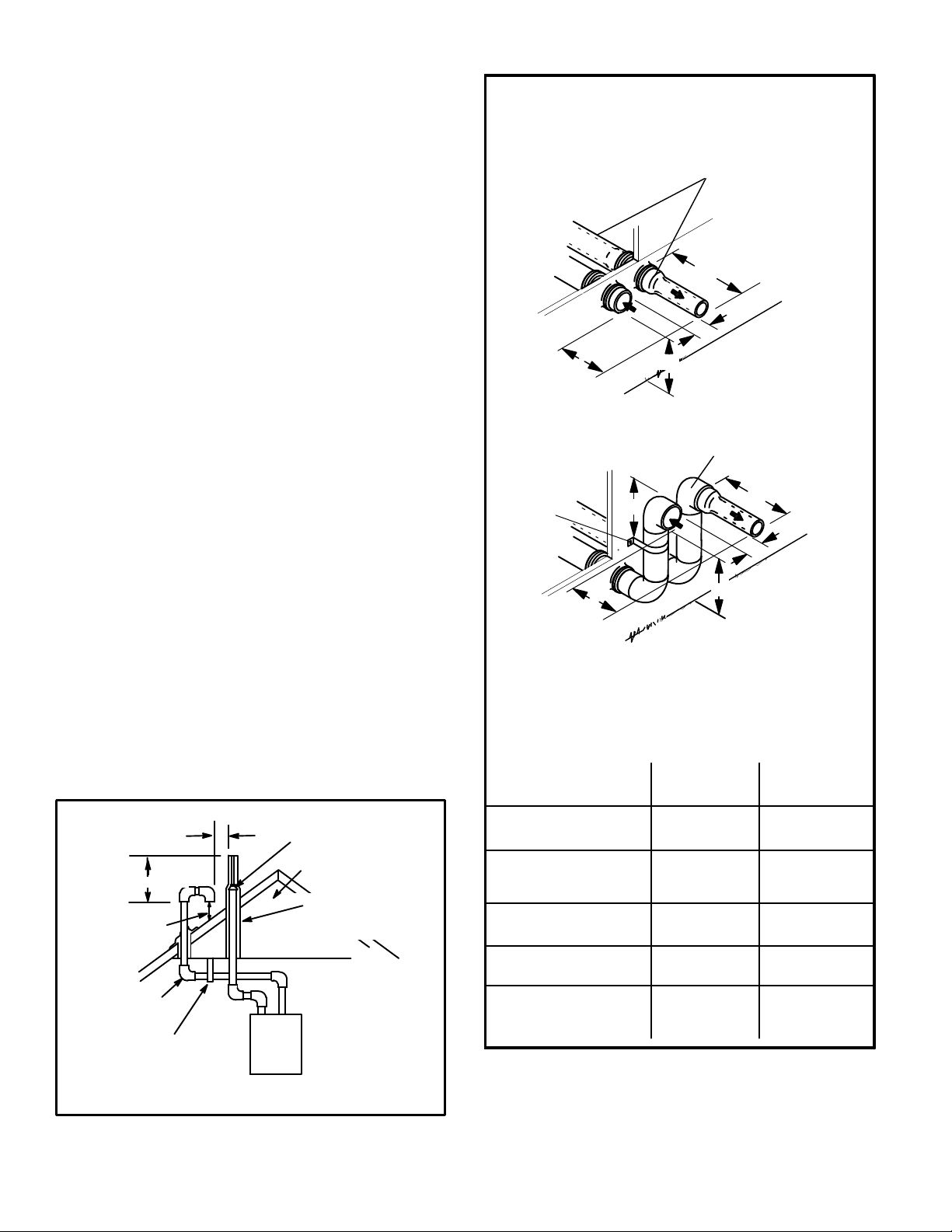
Page 19
Page 20
FIELD−SUPPLIED WALL TERMINATION OR
(15F74) WALL RING TERMINATION KIT
With INTAKE ELBOW
NOTE − FIELD−PROVIDED
REDUCER MAY BE
REQUIRED TO ADAPT
LARGER VENT PIPE SIZE
TO TERMINATION.
1/2" (13mm) ARMAFLEX
INSULATION IN UN-
CONDITIONED SPACE
SIZE TERMINATION
PER TABLE 9
D
* WALL
SUPPORT
B
C
A
1/2" (13mm) ARMAFLEX INSULATION
IN UNCONDITIONED SPACE
E
STRAIGHT
APPPLICATION
D
B
A
C
See venting table 7 for maximum venting lengths with this
arrangement.
* Use wall support every 24" (610 mm). Use two wall supports if
extension is greater than 24" (610 mm) but less than 48" (1219
mm). NOTE − One wall support must be 6" (152 mm) from top of
each pipe (intake and exhaust).
EXTENDED
APPLICATION
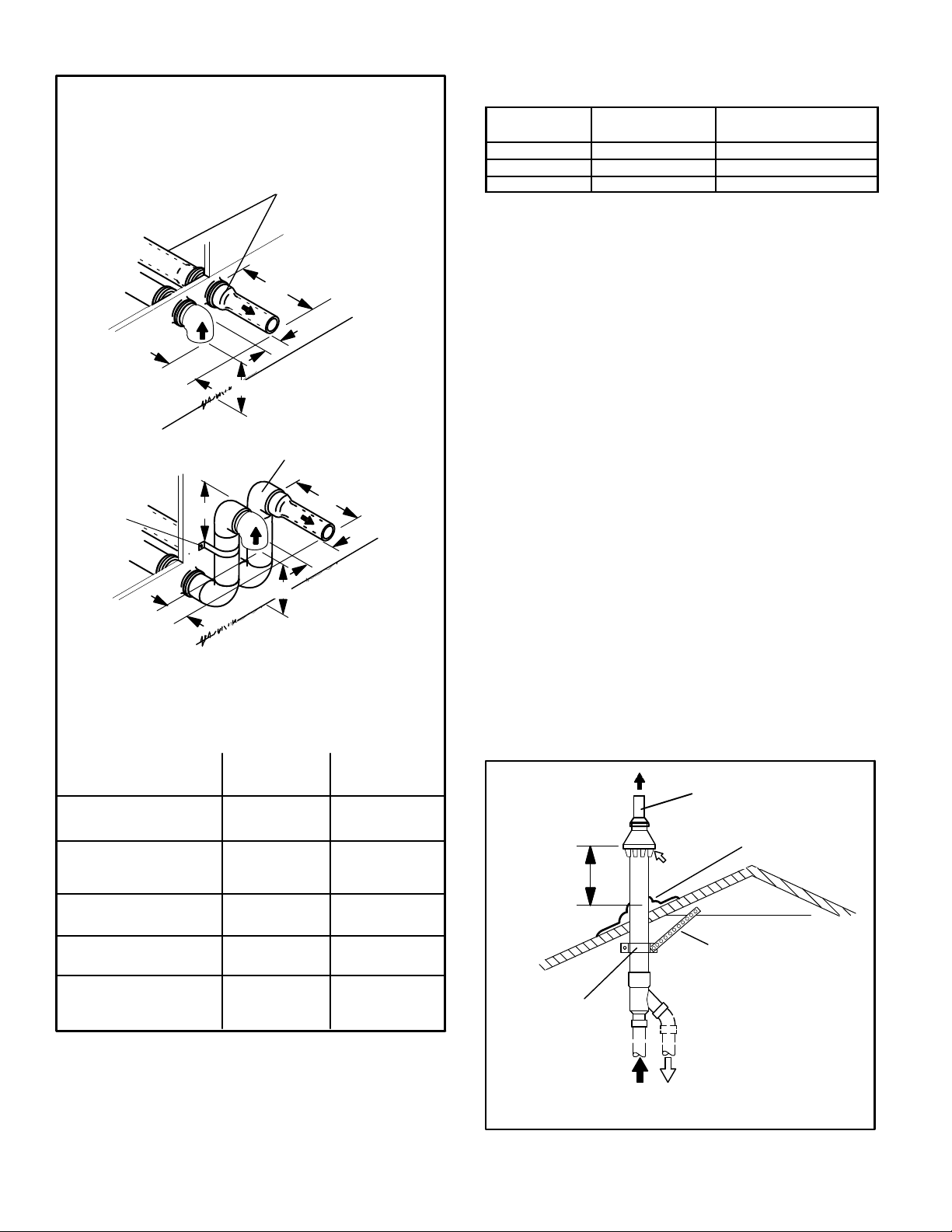
EXHAUST PIPE TERMINATION SIZE REDUCTION
SLP98DFV
MODEL
*070 2", 2−1/2" or 3" 1−1/2"
*090 2", 2−1/2" or 3" 2"
110 2", 2−1/2" or 3" 2"
Exhaust Pipe Size Termination Pipe Size
*SLP98DF −070 and −090 units with the flush−mount termination must use the 1−1/2" accelerator supplied with the
kit.
5 − On field−supplied terminations for side wall exit, ex-
haust piping may extend a maximum of 12 inches
(305mm) for 2" PVC and 20 inches (508mm) for 3"
(76mm) PVC beyond the outside wall. Intake piping
should be as short as possible. See figures 20 and 22.
6 − On field−supplied terminations, a minimum distance
between the end of the exhaust pipe and the end of
the intake pipe without a termination elbow is 8" and a
minimum distance of 6" with a termination elbow. See
figures 20 and 22.
7 − If intake and exhaust piping must be run up a side wall
to position above snow accumulation or other obstructions, piping must be supported every 24"
(610mm) as shown in figures 20 and 22. In addition,
close−coupled wall termination kits must be extended
for use in this application. See figures 30 and 31.
When exhaust and intake piping must be run up an
outside wall, the exhaust piping must be terminated
with pipe sized per table 9.The intake piping may be
equipped with a 90° turndown elbow. Using a turndown elbow will add 5 feet (1.5m) to the equivalent
length of the pipe.
8 − Based on the recommendation of the manufacturer, a
multiple−furnace installation may use a group of up to
four terminations assembled together horizontally, as
shown in figure 25.
TABLE 9
A−Minimum clearance
above grade or average
snow accumulation
B−Maximum horizontal
separation between
intake and exhaust
C−Minimum from
end of exhaust to
inlet of intake
D−Maximum exhaust
pipe length
E−Maximum wall support
distance from top of each
pipe (intake/exhaust)
2" (51mm)
Vent Pipe
12" (508MM) 12" (508MM)
6" (152MM) 6" (152MM)
6" (152MM)
12" (305MM) 20" (508MM)
6" (152MM) 6" (152MM)
3" (76mm)
Vent Pipe
6" (152MM)
FIGURE 22
Page 20
1−1/2" (38mm) accelerator
provided on 71M80 &
44W92 kits for
SLP98DFV−36B−070
12” (305mm)
Minimum
Above Average
Snow
Accumulation
CLAMP
DIRECT VENT CONCENTRIC ROOFTOP TERMINATION
71M80, 69M29 or 60L46 (US)
41W92 or 41W93 (Canada)
INTAKE
SHEET METAL STRAP
(Clamp and sheet metal strap
must be field installed to support
the weight of the termination kit.)
REDUCER MAY BE REQUIRED
PIPE SIZE TO TERMINATION
FLASHING
(Not Furnished)
FIELD−PROVIDED
TO ADAPT LARGER VENT
FIGURE 23
Page 21

FIELD−PROVIDED
REDUCER MAY BE RE-
QUIRED TO ADAPT
LARGER VENT PIPE
SIZE TO TERMINATION.
EXHAUST
AIR
INTAKE
AIR
(Not Furnished)
OUTSIDE
WALL
CLAMP
1−1/2" (38mm) accelerator
provided on 71M80 &
44W92 kits for
SL98DF070V36B
INTAKE
AIR
EXHAUST
12" (305mm) Min.
INTAKE
AIR
above grade or
average snow
accumulation.
GRADE
DIRECT VENT CONCENTRIC WALL TERMINATION
71M80, 69M29 or 60L46 (US)
44W92 or 44W93 (Canada)
FIGURE 24
EXHAUST
VENT
5"
(127mm)
INTAKE
AIR
18" MAX.
(457mm)
EXHAUST VENT
Inches (mm)
INTAKE
AIR
optional intake elbow
Side View
OPTIONAL VENT TERMINATION FOR MULTIPLE UNIT
INSTALLATION OF DIRECT VENT WALL TERMINATION KIT
(22G44, 44J40, 30G28 or 81J20)
12"
(305mm)
5−1/2"
(140mm)
Front View
12" (305mm) Min.
above grade or
average snow ac-
cumulation.
FIGURE 25
AIR
Front View
EXHAUST VENT
INTAKE
AIR
Top View
1/2" (13mm) Foam Insulation
in Unconditioned Space
FIELD−PROVIDED
REDUCER MAY BE
REQUIRED TO
ADAPT LARGER
VENT PIPE SIZE
TO TERMINATION
DIRECT VENT WALL TERMINATION KIT
(22G44 or 44J40)
FIGURE 27
SLP98 DIRECT VENT APPLICATION
USING EXISTING CHIMNEY
3" − 8"
(76mm−
203mm)
Minimum 12" (305MM)
above chimney top
plate or average snow
accumulation
8" − 12"
(203mm − 305mm)
INSULATE
TO FORM
INTAKE PIPE
INSULATION (optional)
SHEET
METAL TOP
PLATE
SEAL
SIZE
TERMINATION
PIPE PER
TABLE 9.
EXHAUST VENT
INTAKE AIR
8" (206mm) MIN.
OUTSIDE WALL
STRAIGHT−CUT OR
ANGLE−CUT IN DIRECTION
OF ROOF SLOPE *
EXHAUST VENT
1/2" (13mm)
WEATHERPROOF
INSULATION
SHOULDER OF FITTINGS
PROVIDE SUPPORT
OF PIPE ON TOP PLATE
3" − 8"
(76mm−
203mm)
ALTERNATE
INTAKE PIPE
EXTERIOR
PORTION OF
CHIMNEY
Front View
INTAKE
AIR
Top View
1/2" (13mm) Foam Insulation
in Unconditioned Space
FIELD−PROVIDED
REDUCER MAY BE
REQUIRED TO
ADAPT LARGER
VENT PIPE SIZE
TO TERMINATION.
DIRECT VENT WALL TERMINATION KIT
(30G28 or 81J20)
FIGURE 26
EXHAUST VENT
SIZE
TERMINATION
PIPE PER
TABLE 9.
EXHAUST VENT
INTAKE AIR
6 (152mm) MIN.
OUTSIDE WALL
Page 21
*SIZE TERMINATION
PIPE PER TABLE 9.
NOTE − Do not discharge exhaust gases directly into any chimney or vent stack. If vertical discharge through an existing unused chimney or stack is required, insert piping
inside chimney until the pipe open end is above top of chimney and terminate as illustrated. In any exterior portion of chimney, the exhaust vent must be insulated.
FIGURE 28
2" EXTENSION FOR
2" PVC PIPE
1" EXTENSION FOR
3" PVC PIPE
4’’
FURNACE
INTAKE
PIPE
FLUSH−MOUNT SIDE WALL TERMINATION KIT 51W11
FURNACE
EXHAUST
PIPE
GLUE EXHAUST
END FLUSH INTO
TERMINATION
1−1/2" ACCELERATOR
(all −070 and −090 units)
FIGURE 29
Page 22

WALL TERMINATION KITS (CLOSE−COUPLE)
EXTENDED VENT FOR GRADE CLEARANCE
If intake and exhaust pipe is less than 12 in. (305 mm)
above snow accumulation or other obstructions,
field−fabricated piping must be installed.
8” (203 mm) min. for 2” (51 mm) & 3” (76 mm) dia. pipe
WALL SUPPORT*
6” (152 mm)
Maximum
INTAKE
AIR
between the end of the exhaust pipe and intake pipe.
12” (305 mm) max. for 2” (51 mm) dia. exhaust
20” (508 mm) max. for 3” (76 mm) dia. exhaust
8” (203 mm) Min.
12” (305 mm) Max. for 2” (51 mm) Dia. Exhaust
20” (508 mm) Max. for 3” (76 mm) Dia. Exhaust
2 inch (51 mm) 22G44 (US)
3 inch (76 mm) 44J40 (US)
EXHAUST
AIR
INTAKE
5” (127 mm)
12” (305 mm) Minimum
Above Grade or Average
Snow Accumulation
GRADE
*Use wall support every 24" (610). Use two supports if
extension is greater than 24" but less than 48".
AIR
REDUCER MAY BE REQUIRED TO ADAPT
LARGER VENT PIPE SIZE TO TERMINATION
FIELD−PROVIDED
12”
(305 mm)
1/2” (13 mm)
FOAM INSULATION
(Field−Furnished)
EXHAUST
AIR
12” (305 mm) Minimum
5−1/2”
(140 mm)
Above Grade or Average
Snow Accumulation
GRADE
WALL TERMINATION KITS (CLOSE−COUPLE)
EXTENDED VENT FOR GRADE CLEARANCE
2 inch (51 mm) 30G28 (WTK Canada)
3 inch (76 mm) 81J20 (WTK Canada)
See installation instructions for additional information.
If intake and exhaust pipe is less than 12 in. (305 mm)
above snow accumulation or other obstructions,
field−fabricated piping must be installed.
WALL SUPPORT*
6” (152 mm)
Maximum
INTAKE
AIR
12” (305 mm) max. for 2” (51 mm) dia. exhaust
20” (508 mm) max. for 3” (76 mm) dia. exhaust
6” (152 mm)
Minimum
6” (152 mm)
Minimum
FIGURE 30
EXHAUST
AIR
12” (305 mm) Minimum
Above Grade or Average
Snow Accumulation
GRADE
REDUCER MAY BE REQUIRED TO ADAPT
LARGER VENT PIPE SIZE TO TERMINATION
FIELD−PROVIDED
12”
(305 mm)
INTAKE
AIR
5” (127 mm)
5−1/2”
(140 mm)
1/2” (13 mm)
FOAM INSULATION
(Field Furnished)
EXHAUST
AIR
12” (305 mm) Minimum
Above Grade or Average
Snow Accumulation
GRADE
12” (305 mm) max. for 2” (51 mm) dia. exhaust
20” (508 mm) max. for 3” (76 mm) dia. exhaust
FIGURE 31
Page 22
*Use wall support every 24" (610). Use two supports if
extension is greater than 24" but less than 48".
Page 23

Condensate Piping
This unit is designed for either right- or left-side exit of condensate piping. Refer to figure 32 for condensate trap locations.
NOTE − If necessary the condensate trap may be installed
up to 5 feet away from the furnace. Piping from furnace
must slope down a minimum of 1/4" per ft. toward trap.
NOTE − Vinyl tubing may be used for condensate drain.
Tubing must be 1−1/4" OD X 1" ID and should be
attached to the drain on the trap using a hose clamp.
CONDENSATE TRAP AND PLUG LOCATION
(shown with left side exit of condensation)
3 − Install drain trap using appropriate PVC fittings, glue
all joints. Glue the provided drain trap as shown in figure 34. Route the condensate line to an open drain.
4 − If unit will be started immediately upon completion of
installation, prime trap per procedure outlined in Unit
Start−Up section.
Condensate line must be sloped downward away from
condensate trap to drain. If drain level is above condensate trap, condensate pump must be used. Condensate drain line should be routed within the conditioned space to avoid freezing of condensate and
blockage of drain line. If this is not possible, a heat
cable kit may be used on the condensate trap and line.
Heating cable kit is available from Lennox in various
lengths; 6 ft. (1.8m) − kit no. 26K68; 24 ft. (7.3m) − kit
no. 26K69; and 50 ft. (15.2m) − kit no. 26K70.
CAUTION
Do not use copper tubing or existing copper
condensate lines for drain line.
1−1/2 in.
(same other right side)
Trap
Plug
(same on left side)
FIGURE 32
1 − Determine which side condensate piping will exit the
unit, location of trap, field−provided fittings and length of
PVC pipe required to reach available drain.
2 − Remove plug (figure 32) from the cold end header box
at the appropriate location on the side of the unit. Install
1/2 NPT male field provided fitting into cold end header box. Do Not Over Tighten. Use teflon tape or ap-
propriate pipe dope.
CONDENSATE TRAP LOCATION
(shown with right side exit of condensation)
Field−Provided Vent
min. 1" Above
Condensate Drain
Trap Can Be Installed a
Maximum Of 5’ From Furnace
1" min.
(PVC Only)
*5’ max.
to drain
*Piping from furnace must slope down a minimum of
1/4" per ft. toward trap.
FIGURE 33
Page 23
Page 24

TRAP / DRAIN ASSEMBLY USING 1/2" PVC OR 3/4" PVC
OPTIONAL Condensate Drain Connection
Adapter 1/2 inch slip X
1/2 inch mpt (Not Furnished)
90° Street Elbow
1/2 inch PVC
(Not Furnished)
1/2 inch mpt (Not Furnished)
1 (25) Minimum
Above Top of Condensate Drain
Connection In Unit
Adapter 1/2 inch slip X
Vent
5 Feet
Maximum
Condensate Drain
Connection In Unit
Condensate Drain
Connection In Unit
Drain Assembly for 1/2 inch Drain Pipe
90° Street Elbow
1/2 inch PVC
To
Drain
Drain Assembly for 3/4 inch Drain Pipe
3/4 inch PVC
(Not Furnished)
To
Drain
OPTIONAL Drain Piping
(furnished)
90° Elbow
90° Elbow 1/2 inch PVC
1/2 inch PVC Pipe
(Not Furnished)
90° Elbow
1/2 inch PVC
(Not Furnished)
To
Drain
90° Elbow
3/4 inch PVC
(Not Furnished)
To
Coupling 3/4 inch slip X slip
Drain
(Not Furnished)
(Not Furnished)
1/2 inch PVC Pipe
(Not Furnished)
1/2 inch PVC Pipe
(Not Furnished)
Coupling 1/2 inch slip X slip
(Not Furnished)
Drain Trap
Assembly
(Furnished)
Drain Trap
Clean Out
Drain Trap Assembly
(Furnished)
7
(178)
Drain Trap Assembly with 1/2 inch Piping
1 inch (25mm) Minimum Above Top of
Condensate Drain Connection In Unit
Vent
Condensate Drain
Connection In Unit
To
Drain
FIGURE 34
Page 24
Drain Trap Assembly with 3/4 inch Piping
1 inch (25mm) Minimum Above Top of
Condensate Drain Connection In Unit
Vent
Condensate Drain
Connection In Unit
To
Drain
Page 25

CAUTION
A separate drain line must be run to the drain from
the condensate trap to ensure proper drainage and
pressure switch operation. DO NOT connect the condensate trap drain into the drain line from the evaporator coil.
SL98DFV with Evaporator Coil
Field−Provided Vent
Condensate trap and
evaporator coil must drain
separately as shown.
4 − Piping should be sloped 1/4 inch per 15 feet (6mm per
5.6m) upward toward the gas meter from the furnace.
The piping must be supported at proper intervals, every 8 to 10 feet (2.44 to 3.05m), using suitable hangers
or straps. Install a drip leg in vertical pipe runs to serve as
a trap for sediment or condensate.
5 − A 1/8" N.P.T. plugged tap or pressure post is located on
the gas valve to facilitate test gauge connection. See
figures 45.
6 − In some localities, codes may require installation of a
manual main shut-off valve and union (furnished by installer) external to the unit. Union must be of the
ground joint type.
IMPORTANT
Compounds used on threaded joints of gas piping
must be resistant to the actions of liquified petroleum gases.
Drain
FIGURE 35
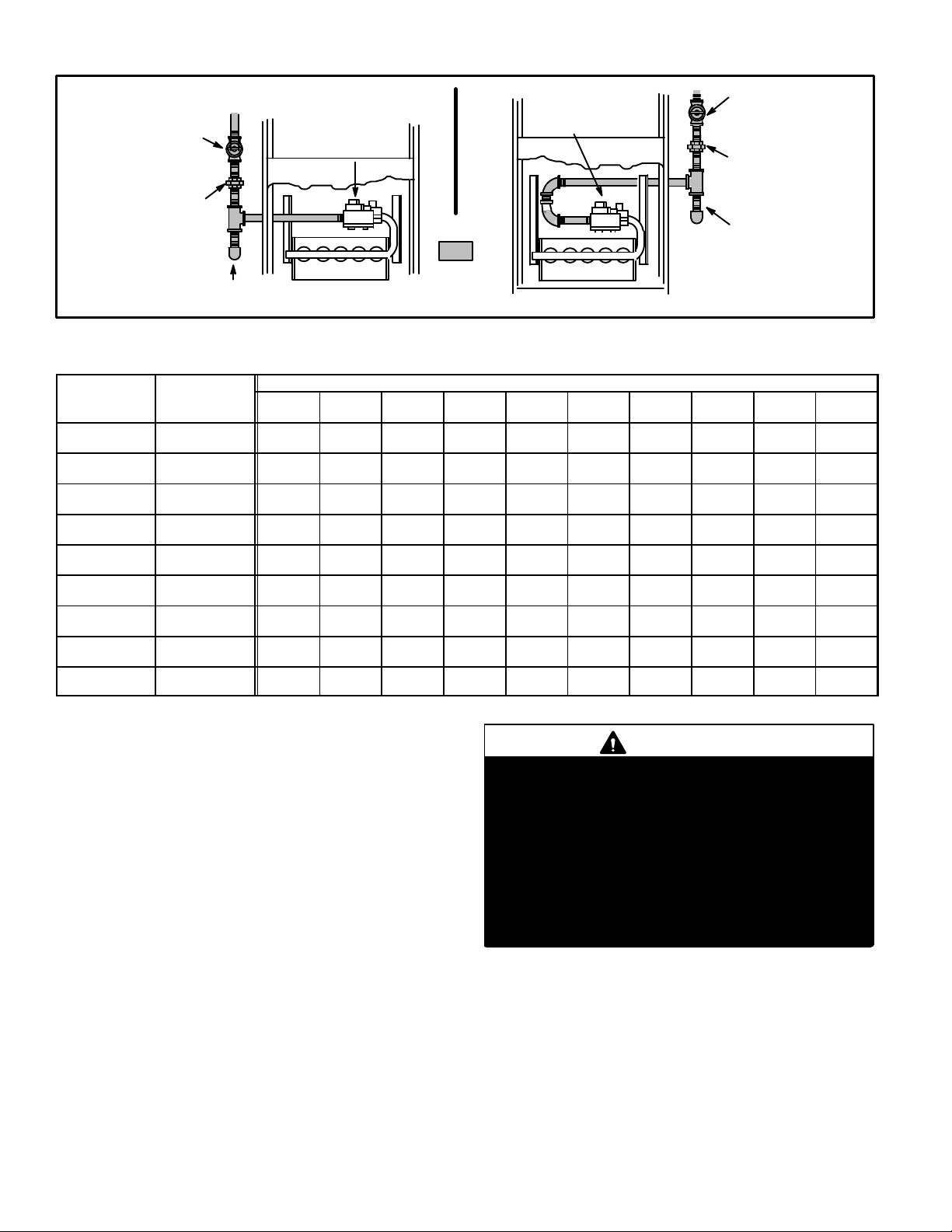
Gas Piping
CAUTION
If a flexible gas connector is required or allowed by
the authority that has jurisdiction, black iron pipe
shall be installed at the gas valve and extend outside
the furnace cabinet.
WARNING
Do not exceed 600 in−lbs (50 ft.−lbs) torque when attaching the gas piping to the gas valve.
1 − Gas piping may be routed into the unit through either
the left- or right-hand side. Supply piping enters into
the gas valve from the side of the valve as shown in
figure 37.
2 − When connecting gas supply, factors such as length of
run, number of fittings and furnace rating must be considered to avoid excessive pressure drop. Table 10
lists recommended pipe sizes for typical applications.
NOTE − Use two wrenches when connecting gas piping to avoid transferring torque to the manifold.
3 − Gas piping must not run in or through air ducts, clothes
chutes, chimneys or gas vents, dumb waiters or elevator shafts. Center gas line through piping hole. Gas
line should not touch side of unit. See figure 37.
MANUAL MAIN SHUT−OFF
VALVE WILL NOT HOLD
NORMAL TEST PRESSURE
1/8" N.P.T.
PLUGGED
TAP
CAP
FIGURE 36
Leak Check
After gas piping is completed, carefully check all piping
connections (factory− and field−installed) for gas leaks. Use
a leak detecting solution or other preferred means.
The furnace must be isolated from the gas supply system
by closing its individual manual shut-off valve during any
pressure testing of the gas supply system at pressures less
than or equal to 1/2 psig (3.48 kPa, 14 inches w.c.).
FURNACE
ISOLATE
GAS VALVE
IMPORTANT
When testing gas lines using pressures in excess of
1/2 psig (3.48 kPa), gas valve must be disconnected
and isolated. See figure 36. Gas valves can be damaged if subjected to pressures greater than 1/2 psig
(3.48 kPa).
WARNING
Failure to follow the safety warnings exactly could
result in serious injury, death, or property damage.
Never use an open flame to test for gas leaks. Check
all connections using a commercially available soap
solution made specifically for leak detection. Some
soaps used for leak detection are corrosive to certain
metals. Carefully rinse piping thoroughly after leak
test has been completed.
FIRE OR EXPLOSION HAZARD
Page 25
Page 26
MANUAL
MAIN SHUT−OFF
VALV E
(1/8 in. NPT
plugged tap shown)
GROUND
JOINT
UNION
Left Side Piping
(Standard)
AUTOMATIC
GAS VALVE
(with manual
shut−off valve)
AUTOMATIC
GAS VALVE
(with manual
shut−off valve)
MANUAL
MAIN SHUT−OFF
VALV E
(1/8 in. NPT
plugged tap
shown)
GROUND
JOINT
UNION
DRIP LEG
Right Side Piping
DRIP LEG
FIELD
PROVIDED
AND INSTALLED
NOTE − BLACK IRON PIPE ONLY TO BE ROUTED INSIDE OF CABINET
FIGURE 37
TABLE 10
GAS PIPE CAPACITY − FT3/HR (kL/HR)
Nominal
Iron Pipe Size
−Inches(mm)
1/2
(12.7)
3/4
(19.05)
1
(25.4)
1−1/4
(31.75)
1−1/2
(38.1)
2
(50.8)
2−1/2
(63.5)
3
(76.2)
4
(101.6)
Internal
Diameter
−Inches(mm)
.622
(17.799)
.824
(20.930)
1.049
(26.645)
1.380
(35.052)
1.610
(40.894)
2.067
(52.502)
2.469
(67.713)
3.068
(77.927)
4.026
(102.260)
10
(3.048)20(6.096)30(9.144)40(12.192)50(15.240)60(18.288)70(21.336)80(24.384)90(27.432)
175
(4.96)
360
(10.19)
680
(19.25)
1400
(39.64)
2100
(59.46)
3950
(111.85)
6300
(178.39)
11000
(311.48)
23000
(651.27)
120
(3.40)
250
(7.08)
465
(13.17)
950
(26.90)
460
(41.34)
2750
(77.87)
4350
(123.17)
7700
(218.03)
15800
(447.39)
97
(2.75)
200
(5.66)
375
(10.62)
770
(21.80)
1180
(33.41)
2200
(62.30)
3520
(99.67)
6250
(176.98)
12800
(362.44)
NOTE − Capacity given in cubic feet of gas per hour (kilo liters of gas per hour) and based on 0.60 specific gravity gas.
Length of Pipe−Feet(m)
82
(2.32)
170
(4.81)
320
(9.06)
660
(18.69)
990
(28.03)
1900
(53.80)
3000
(84.95)
5300
(150.07)
10900
(308.64)
73
(2.07)
151
(4.28)
285
(8.07)
580
(16.42)
900
(25.48)
1680
(47.57)
2650
(75.04)
4750
(134.50)
9700
(274.67)
66
(1.87)
138
(3.91)
260
(7.36)
530
(15.01)
810
(22.94)
1520
(43.04)
2400
(67.96)
4300
(121.76)
8800
(249.18)
61
(1.73)
125
(3.54)
240
(6.80)
490
(13.87)
750
(21.24)
1400
(39.64)
2250
(63.71)
3900
(110.43)
8100
(229.36)
Removal of the Furnace from Common Vent
WARNING
In the event that an existing furnace is removed from a
venting system commonly run with separate gas appliances, the venting system is likely to be too large to
properly vent the remaining attached appliances.
Conduct the following test while each appliance is operating and the other appliances (which are not operating) remain connected to the common venting system. If the
venting system has been installed improperly, you must
correct the system as indicated in the general venting requirements section.
CARBON MONOXIDE POISONING HAZARD
Failure to follow the steps outlined below for each
appliance connected to the venting system being
placed into operation could result in carbon monoxide poisoning or death.
The following steps shall be followed for each appliance connected to the venting system being
placed into operation, while all other appliances
connected to the venting system are not in
operation:
(Alternate)
57
(1.61)
118
(3.34)
220
(6.23)
460
(13.03)
690
(19.54)
1300
(36.81)
2050
(58.05)
3700
(104.77)
7500
(212.37)
53
(1.50)
110
(3.11)
205
(5.80)
430
(12.18)
650
(18.41)
1220
(34.55)
1950
(55.22)
3450
(97.69)
7200
(203.88)
100
(30.480)
50
(1.42)
103
(2.92)
195
(5.52)
400
(11.33)
620
(17.56)
1150
(32.56)
1850
(52.38)
3250
(92.03)
6700
(189.72)
Page 26
Page 27

1 − Seal any unused openings in the common venting sys-
tem.
2 − Inspect the venting system for proper size and horizontal
pitch. Determine that there is no blockage, restriction,
leakage, corrosion, or other deficiencies which could
cause an unsafe condition.
3 − Close all building doors and windows and all doors be-
tween the space in which the appliances remaining
connected to the common venting system are located
and other spaces of the building. Turn on clothes dryers and any appliances not connected to the common
venting system. Turn on any exhaust fans, such as
range hoods and bathroom exhausts, so they will operate at maximum speed. Do not operate a summer exhaust fan. Close fireplace dampers.
4 − Follow the lighting instructions. Turn on the appliance
that is being inspected. Adjust the thermostat so that
the appliance operates continuously.
5 − After the main burner has operated for 5 minutes, test
for leaks of flue gases at the draft hood relief opening.
Use the flame of a match or candle.
6 − After determining that each appliance connected to the
common venting system is venting properly, (step 3)
return all doors, widows, exhaust fans, fireplace dampers, and any other gas−burning appliances to their previous mode of operation.
7 − If a venting problem is found during any of the preced-
ing tests, the common venting system must be modified to correct the problem.
Resize the common venting system to the minimum
vent pipe size determined by using the appropriate
tables in Appendix G. (These are in the current standards of the National Fuel Gas Code ANSI Z223.1.
Electrical
ELECTROSTATIC DISCHARGE (ESD)
Precautions and Procedures
CAUTION
Electrostatic discharge can affect electronic components. Take precautions during furnace installation and service to protect the furnace’s electronic
controls. Precautions will help to avoid control exposure to electrostatic discharge by putting the furnace, the control and the technician at the same
electrostatic potential. Neutralize electrostatic
charge by touching hand and all tools on an unpainted unit surface, such as the gas valve or blower
deck, before performing any service procedure.
INTERIOR MAKE−UP BOX
(FACTORY− INSTALLED LEFT SIDE)
MAKE−UP
Left side
BOX INSIDE
CABINET
FIGURE 38
EXTERIOR MAKE−UP BOX
(FIELD PROVIDED RIGHT SIDE)
MAKE−UP
BOX
OUTSIDE
CABINET
Right Side
FIGURE 39
The unit is equipped with a make−up box on the left hand
side of the cabinet. A field−provided make−up box can be
installed on the exterior of the right side of the furnace to
facilitate installation. If the make−up box is moved to the
right side, clip the wire ties that bundle the wires together
and install on the outside of the cabinet. See figure 39. The
excess wire must be pulled into the blower compartment.
Secure the excess wire to the existing harness to protect it
from damage.
Refer to figure 40 for unit field wiring. See figures 41 and 42
for icomfort Touch thermostat wiring in communicating
applications. Table 14 shows DIP switch and on−board link
settings for non−communicating thermostat applications.
Typical wiring schematic is shown in figure 43.
Page 27
Page 28

1 − The power supply wiring must meet Class I restric-
tions. Protected by either a fuse or circuit breaker, select circuit protection and wire size according to unit
nameplate.
NOTE − Unit nameplate states maximum current draw. See
table for maximum over−current protection.
TABLE 11
SLP98DF Model
07036B, 09036C, 09048C 15
09060C, 11060C 20
Maximum Over−Current
Protection (Amps)
2 − Holes are on both sides of the furnace cabinet to facili-
tate wiring.
3 − Install a separate (properly sized) disconnect switch
near the furnace so that power can be turned off for
servicing.
4 − Before connecting the thermostat or the power wiring,
check to make sure the wires will be long enough for
servicing at a later date. Remove the blower access
panel to check the length of the wire.
5 − Complete the wiring connections to the equipment.
Use the provided unit wiring diagram and the field wiring diagram shown in figure 40 and table 14. Use
18−gauge wire or larger that is suitable for Class II rating for thermostat connections.
NOTE − Do NOT make a wire connection between
the room thermostat L terminal and the L terminal
of the SLP98DFV integrated control unless this is a
communicating thermostat installation with a non−
communicating outdoor unit.
6 − Electrically ground the unit according to local codes or,
in the absence of local codes, according to the current
National Electric Code (ANSI/NFPA No. 70) for the
USA and current Canadian Electric Code part 1 (CSA
standard C22.1) for Canada. A green ground wire is
provided in the field make−up box.
7 − One line voltage EAC" 1/4" spade terminal is provided
on the furnace integrated control. Any electronic air
cleaner rated up to one amp can be connected to this
terminal with the neutral leg of the circuit being connected to one of the provided neutral terminals. See
figure 44 for location of terminal. This terminal is energized when the indoor blower is operating.
8 − One line voltage HUM" 1/4" spade terminal is provided
on the furnace integrated control. Any humidifier rated
up to one amp can be connected to this terminal with
the neutral leg of the circuit being connected to one of
the provided neutral terminals. See figure 44 for location of terminal. This terminal is energized in the heating mode when the indoor blower is is operating.
9 − One 24V H" terminal is provided on the furnace inte-
grated control terminal block. Any humidifier rated up
to 0.5 amp can be connected to this terminal with the
ground leg of the circuit being connected to either
ground or the C" terminal. See figure 44 for location of
terminal.
10 −Install the room thermostat according to the instruc-
tions provided with the thermostat. See table 14 for
thermostat connections. If the furnace is being
matched with a heat pump, refer to the instruction
packaged with the dual fuel thermostat.
NOTE − The discharge air temperature sensor is intended
to be mounted downstream of the heat exchanger and air
conditioning coil. It must be placed in free airflow, where
other accessories (humidifiers, UV lights etc.) will not interfere with its accuracy. Wiring distance between the furnace
and discharge air sensor should not exceed 10 ft. when
wired with 18−gauge thermostat wire.
TABLE 12
Run Length Non Communicating
Wire Run Length AWG # Insulation/Core Types
Less than 100’ (30m) 18
More than 100’ (30m) 16
Color−coded, temperature
rating 95ºF (35ºC) minimum, solid core. (Class II
Rated Wiring)
TABLE 13
Run Length Communicating
Wire Run Length AWG # Insulation/Core Types
Maximum length of wiring
for all connections on the
RSBus is limited to 1500
feet (457 meters).
18
Color−coded, temperature
rating 95ºF (35ºC) minimum, solid core. (Class II
Rated Wiring)
Thermostat Selection
The SLP98DFV is designed to operate in a variable rate capacity mode using a two−stage thermostat. The SLP98DFV
will automatically adjust firing rate based upon thermostat
cycle times.
The icomfort Touch thermostat must be used in communicating applications. Refer to the instructions provided
with the thermostat for installation, set−up and operation.
For optimal performance in non−communicating applications, Lennox recommends use of a ComfortSense® 7000
high quality electronic digital thermostat or any other with
adjustable settings for 1st stage / 2nd stage on / off differentials and adjustable stage timers.
Lennox recommends the following two−stage thermostat
set−up for optimal variable rate capacity mode:
First heat stage differential set to 1/2 to 1 degree F; second
heat stage differential set to 1/2 or 1 degree F; second heat
stage upstage timer disabled, or set to maximum (1 hr minimum).
Indoor Blower Speeds
NOTE − When the SLP98DFV is used with icomfort
Toucht thermostat, proper indoor blower speed selections are made by the communicating thermostat.
Page 28
Page 29

1 − When the thermostat is set to FAN ON," the indoor
blower will run continuously at a percentage of the second−stage cooling speed when there is no cooling or
heating demand. The percentage is set using DIP
switches 6 and 7.
2 − When the SLP98DFV is running in the heating mode,
the integrated control will automatically adjust the
blower speed to match the furnace firing rate. This
speed can be adjusted up or down by 7.5% or 15% using DIP switches 14 through 16 for the low heat speed
and 17 through 19 for the high heat speed.
3 − When there is a cooling demand, the indoor blower will
run on the cooling speed designated by the positions
of DIP switches 8 through 11.
TYPICAL SLP98DFV FIELD WIRING DIAGRAM FOR STANDARD
NON−COMMUNICATING THERMOSTAT
USE COPPER CONDUCTORS ONLY.
FIELD INSTALLED CLASS II 24V
FIELD INSTALLED LINE VOLTAGE
Generator Use − Voltage Requirements
The following requirements must be kept in mind when
specifying a generator for use with this equipment:
The furnace requires 120 volts +
10% (Range: 108
volts to 132 volts).
The furnace operates at 60 Hz +
5% (Range: 57 Hz to
63 Hz).
The furnace integrated control requires both polarity
and proper ground. Both polarity and proper grounding
should be checked before attempting to operate the
furnace on either permanent or temporary power.
Generator should have a wave form distortion of less
than 5% THD (total harmonic distortion).
1 234 567
8
12
91011
13
14 151617
19
18
FIGURE 40
Page 29
Page 30

icomfort Touch Thermostat with SLP98DFV
and Non−Communicating Outdoor Unit
icomfort Touch Thermostat with SLP98DFV
and icomfort−ENABLED Outdoor Unit
icomfort Touch Thermostat
icomfort−Enabled SLP98DFV Indoor Furnace
Non−Communicating Outdoor Air Conditioner
icomfort−
ENABLED
SLP98DFV
OPTIONAL
DISCHARGE
AIR SENSOR
icomfort Touch
THERMOSTAT
CLIP Y1 TO Y2 FOR
TWO−STAGE OPERATION
FURNACE
OPTIONAL
OUTDOOR
AIR SENSOR
NON−COMMUNICATING
OUTDOOR AIR
CONDITIONING UNIT −
1 OR 2 STAGE
icomfort Touch Thermostat
icomfort−Enabled SLP98DFV Indoor Furnace
icomfort−Enabled Outdoor Air Conditioner or Heat Pump
icomfort−
ENABLED
SLP98DFV
FURNACE
OPTIONAL
DISCHARGE
AIR SENSOR
OPTIONAL
OUTDOOR
AIR SENSOR
icomfort TOUCH
THERMOSTAT
icomfort− ENABLED
OUTDOOR AIR CONDITIONING
OR HEAT PUMP UNIT
FIGURE 41
Page 30
Page 31

Optional Accessories for use with any icomfort Touch System
DISCHARGE AIR SENSOR
icomfort Touch
THERMOSTAT
NOTE: 24V UV LIGHT
APPLICATIONS
Furnace transformer will not have adequate va to power 24v UV light applications. An additional transformer
for UV light applications is required.
icomfort−
ENABLED
SLP98DFV
FURNACE
NOTE: icomfort THERMOSTAT SENSES HUMIDITY & CONTROLS
24V H" OUTPUT (& 120V H" OUTPUT) TO CYCLE HUMIDIFIER
BASED ON DEMAND. NO OTHER CONTROL OR HUMIDISTAT
REQUIRED.
OPTIONAL OUTDOOR AIR SENSOR FOR USE WITH HUMIDIFIER (IF NOT ALREADY IN THE SYSTEM FOR OTHER
FUNCTIONS. BUILT INTO ALL icomfort OUTDOOR UNITS).
icomfort−
ENABLED
SLP98DFV
FURNACE
icomfort−
ENABLED
SLP98DFV
FURNACE
HEPA BYPASS FILTER
X2680 HEPA
INTERLOCK KIT
LVCS VENTILATION
CONTROL SYSTEM
SEE LVCS VENTILATION
INSTRUCTIONS FOR
DAMPER & SENSOR WIRING
PASS INDOOR BLOWER
MOTOR COMMON WIRE
THROUGH CURRENT LOOP.
SEE HEPA INTERLOCK KIT
FOR INSTALLATION DETAILS
icomfort−
ENABLED
SLP98DFV
FURNACE
icomfort−
ENABLED
SLP98DFV
FURNACE
(C)
icomfort− ENABLED
OUTDOOR AIR
CONDITIONING OR
HEAT PUMP UNIT
NON−COMMUNICATING
1 OR 2 STAGE AC OR HP UNIT
(C)
(disables out-
door unit only)
FIGURE 42
Page 31
Page 32

Thermostat
1Heat / 1 Cool
NOTE − Use DIP
switch 3 to set
second−stage
heat ON delay.
OFF−7 minutes.
ON−12 minutes.
TABLE 14
Field Wiring Connections for Non−Communicating Thermostat Applications
DIP Switch Settings and On−Board Links (figure 44)
W914
DIP Switch 1
W915
(Y1 to Y2)
Two−Stage
Cooling
(DS to R)
Dehumidifi-
cation or
Harmony
W951
(O to R)
Heat Pumps
Wiring Connections
III
ON Intact Intact Intact
S1
T’STAT
CONTROL
TERM. STRIP
OUTDOOR
UNIT
*
1 Heat / 2 Cool
NOTE − Use DIP
switch 3 to set
second−stage
heat ON delay.
OFF−7 minutes.
ON−12 minutes.
1 Heat / 2 Cool
with t’stat with
dehumidification
mode
NOTE − Use DIP
switch 3 to set
second−stage
heat ON delay.
OFF−7 minutes.
ON−12 minutes.
ON Cut Intact Intact
ON Cut Cut Intact
S1
T’STAT
S1
T’STAT
CONTROL
TERM. STRIP
CONTROL
TERM. STRIP
OUTDOOR
UNIT
*
OUTDOOR
UNIT
*
* R" required on some units.
Page 32
Page 33

TABLE 14
Field Wiring for Non−Communicating Applications (Continued)
DIP Switch Settings and On−Board Links (figure 44)
W914
(DS to R)
Dehumidifi-
cation or
Harmony
W951
(O to R)
Heat Pumps
Thermostat
DIP Switch 1
W915
(Y1 to Y2)
Two−Stage
Cooling
III
2 Heat / 2 Cool OFF Cut Intact Intact
Wiring Connections
S1
T’STAT
CONTROL
TERM. STRIP
OUTDOOR
UNIT
*
2 Heat / 2 Cool
OFF Cut Cut Intact
with t’stat with
dehumidification mode
2 Heat / 1 Cool OFF Intact Intact Intact
S1
T’STAT
S1
T’STAT
CONTROL
TERM. STRIP
CONTROL
TERM. STRIP
OUTDOOR
UNIT
*
OUTDOOR
UNIT
*
* R" required on some units.
Page 33
Page 34

Thermostat
Dual Fuel
Single−Stage
Heat Pump
ComfortSense
7000 L7724U
thermostat w/
dual fuel capabilities
Capable of
2−stage gas
heat control
®
TABLE 14
Field Wiring for Non−Communicating Applications (Continued)
DIP Switch Settings and On−Board Links (figure 44)
W914
DIP Switch
W915
(Y1 to Y2)
Two−Stage
Cooling
(DS to R)
Dehumidifi-
cation or
Harmony
W951
(O to R)
Heat Pumps
III
DIP Switch 1
Intact Intact Cut
OFF
L7724U
T’STAT
H
L
Y2
D
B
Wiring Connections
CONTROL
TERM. STRIP
Y2
HEAT PUMP
67M41*
L
Y
T
T
Dual Fuel
Two−Stage
Heat Pump
ComfortSense
®
DIP Switch 1
OFF
Cut Intact Cut
L7724U
T’STAT
H
CONTROL TERM.
STRIP
67M41*
HEAT PUMP
7000 L7724U
thermostat w/
dual fuel capabilities
L
Capable of
2−stage gas
Y2
heat control
D
B
T
T
outdoor
sensor
* Connect W1 to W1 ONLY if using defrost tempering kit 67M41
NOTE − Do NOT make a wire connection between the room thermostat L terminal and the L terminal of the SLP98DFV
integrated control.
outdoor
sensor
L
Y2
out blue
Page 34
Page 35

TYPICAL SLP98DFV WIRING DIAGRAM
FIGURE 43
Page 35
Page 36

Integrated Control
COMBUSTION
AIR INDUCER
CONNECTOR
DIAGNOSTIC
PUSH BUTTON
DIP SWITCHES
OUTDOOR AIR
SENSOR
TERMINALS
DISCHARGE AIR
SENSOR
FACTORY TEST
HEADER PINS.
FACTORY USE ONLY.
TB83 OUTDOOR
TB84 INDOOR
TERMINALS
FLAME
SENSE
INTEGRATED CONTROL
+
7−SEGMENT
DIAGNOSTIC LED
HUM
EAC
W915
W951
W914
NEUTRAL
TERMINALS
IGNITOR
CONNECTOR
LINE VOLTAGE
TERMINALS
INDOOR
BLOWER
CONNECTOR
W915 Y1 TO Y2
W951 R TO O
W914 R TO DS
L − use only with
communicating T’stat and
non−communicating outdoor
unit.
RS−BUS LINK (TB82, future use)
I+ = DATA HIGH CONNECTION
I − = DATA LOW CONNECTION
RS−BUS OUTDOOR (TB83)
R = 24VAC
I + = DATA HIGH CONNECTION
I − = DATA LOW CONNECTION
C = 24VAXC COMMON
RS−BUS INDOOR (TB84)
R = 24VAC
I + = DATA HIGH CONNECTION
I − = DATA LOW CONNECTION
C = 24VAXC COMMON
1/4" QUICK CONNECT TERMINALS
HUM = 120 VAC OUTPUT TO HUMIDIFIER
XMFR = 120 VAC OUTPUT TO TRANSFORMER
LI = 120 VAC INPUT TO CONTROL
CIRC = 120 VAC OUTPUT TO CIRCULATING BLOWER
EAC = 120 VAC OUTPUT TO ELECTRICAL AIR CLEANER
NEUTRALS = 120 VAC NEUTRAL
THERMOSTAT CONNECTIONS (TB1)
DS = DEHUMIDIFICATION SIGNAL
W2 = HEAT DEMAND FROM 2ND STAGE T/STAT
W1 = HEAT DEMAND FROM 1ST STAGE T/STAT
R = CLASS 2 VOLTAGE TO THERMOSTAT
G = MANUAL FAN FROM T’STAT
C = THERMOSTAT SIGNAL GROUNCONNECTED TO
TRANSFORMER GRD (TR) & CHASIS GROUND (GRD)
Y1 = THERMOSTAT 1ST STAGE COOL SIGNAL
Y2 = THERMOSTAT 2ND STAGE COOL SIGNAL
O = THERMOSTAT SIGNAL TO HEAT PUMP
H = 24V HUMIDIFIER OUTPUT. DO NOT CONNECT
L = USE ONLY WITH A COMMUNICATING THERMOSTAT
DH = DEHUMIDIFICATION OUTPUT COMMUNICATING
REVERSING VALVE
®
TO COMFORTSENSE
THERMOSTAT
AND A NON−COMMUNICATING OUTDOOR UNIT
THERMOSTAT ONLY
FIGURE 44
Page 36
Page 37

Non−Communicating Thermostat Selection Switch Settings
TABLE 15
Operation Thermostat Switch 1 Switch 2 Switch 3
Variable Capacity Heat
Two−Stage Off On Off
(35% to 100%)
Three−Stage Heat
(35%, 70%, 100%)
Single−Stage On Off 2nd stage delay
OFF = 7 minutes
ON = 12 minutes
3rd stage delay
10 minutes fixed
Two−Stage Heat (W1 70%, W2 100%) Two−Stage Off Off Off
NOTE − When the SLP98DFV is used with an icomfort
Toucht communicating thermostat, all indoor blower
speed selections and DIP switch settings are made by the
communicating thermostat.
SLP98DFV units are equipped with an integrated control.
This control manages ignition timing, combustion air inducer speed, heating mode fan off delays and indoor blower
speeds based on selections made using the control DIP
switches and on−board links. The control includes an internal Watchguard feature which automatically resets the
ignition control when it has been locked out.
NOTE − All DIP switches are factory shipped in the
OFF" position.
Heating Operation DIP Switch Settings −− Figure 44
Switch 1 −− Thermostat Selection −− This unit may be used
with either a single−stage or two−stage thermostat. The
thermostat selection is made using a DIP switch which
must be properly positioned for the particular application.
The DIP switch is factory−positioned for use with a two−
stage thermostat. If a single−stage thermostat is to be used,
the DIP switch must be repositioned. See table 15.
Switch 2 −− Operating Mode with Two−Stage Thermostat −− If a two−stage thermostat is used, the furnace can
operate in either variable−capacity or conventional two−
stage mode. When variable−capacity mode is selected, the
firing rate of the unit is varied to maximize comfort. Conventional two−stage mode is the factory default setting. See
table 15.
Switch 3 −− Second−Stage Heat On Delay −− If a single−
stage thermostat is used, the integrated control can be
used to energize second−stage heat after either 7 minutes
or 12 minutes of first−stage heat operation. See table 15.
Switches 4 and 5 −− Blower−Off Delay −− The blower−on
delay of 45 seconds is not adjustable. The blower−off delay
(time that the blower operates after the heating demand
has been satisfied) can be adjusted by moving switches 4
and 5 on the integrated control. The unit is shipped from the
factory with a blower−off delay of 90 seconds. The blower
off delay affects comfort and is adjustable to satisfy individual applications. Adjust the blower off delay to achieve a
supply air temperature between 90° and 110°F at the exact
moment that the blower is de−energized. Longer off delay
settings provide lower supply air temperatures; shorter settings provide higher supply air temperatures. Table 16 provides the blower off timings that will result from different
switch settings.
TABLE 16
Blower Off Delay Switch Settings
Blower Off Delay
(Seconds)
Switch 4 Switch 5
60 Off On
90 (factory) Off Off
120 On Off
180 On On
Indoor Blower Operation DIP Switch Settings
Switches 6 and 7 −− Continuous Indoor Fan OperationBlower Speed −− The unit is shipped from the factory with
the DIP switches positioned for medium low (2) speed during continuous indoor blower operation. The table below
provides the continuous blower speeds that will result from
different switch settings. Refer to tables beginning on page
37 for corresponding cfm values.
TABLE 17
Continuous Indoor Blower Operation −− Blower Speeds
Speed Switch 6 Switch 7
1 − Low Off On
2 − Medium Low
(Factory)
Off Off
3 − Medium High On Off
4 − High On On
Page 37
Page 38

Switches 8 and 9 −− Cooling Mode Blower Speed −− The
unit is shipped from the factory with the DIP switches positioned for high speed (4) indoor blower motor operation
during the cooling mode. The table below provides the
cooling mode blower speeds that will result from different
switch settings. Refer to tables beginning on page 37 for
corresponding cfm values.
TABLE 18
Cooling Mode Blower Speeds
Speed Switch 8 Switch 9
1 − Low On On
2 − Medium Low Off On
3 − Medium High On Off
4 − High (Factory) Off Off
Cooling Mode Blower Speed Ramping
TABLE 20
Ramping Option Switch 12 Switch 13
A (Factory) Off Off
B On Off
C Off On
D On On
Ramping Option A (Factory Selection)
Motor runs at 50% for 30 seconds.
Motor then runs at 82% for approximately 7−1/2 minu-
tes.
If demand has not been satisfied after 7−1/2 minutes,
motor runs at 100% until demand is satisfied.
Once demand is met, motor runs at 50% for 30 sec-
onds then ramps down to stop.
Switches 10 and 11 −− Cooling Mode Blower Speed Adjustment −− The unit is shipped from the factory with the
DIP switches positioned for NORMAL (no) adjustment.
The DIP switches may be positioned to adjust the blower
speed by +10% or −10% to better suit the application. Table
19 provides blower speed adjustments that will result from
different switch settings. Refer to tables beginning on page
37 for corresponding cfm values.
With switches 10 and 11 set to ON, motor will bypass ramping profiles and all delays and will immediately run at selected COOLING speed upon a call for cool. LED will continue to operate as normal. This mode is used to check
motor operation.
TABLE 19
Cooling Mode Blower Speed Adjustment
Adjustment Switch 10 Switch 11
+10% (approx.) On Off
NORMAL (Factory) Off Off
−10% (approx.) Off On
MOTOR TEST On On
Switches 12 and 13 −− Cooling Mode Blower Speed
Ramping −− Blower speed ramping may be used to en-
hance dehumidification performance. The switches are
factory set at option A which has the greatest effect on
blower motor performance. Table 20 provides the cooling
mode blower speed ramping options that will result from
different switch settings. The cooling mode blower speed
ramping options are detailed below.
NOTE − The off portion of the selected ramp profile only applies during heat pump operation in dual fuel applications.
OFF
1/2 MIN
50% CFM
7 1/2 MIN
82% CFM
COOLING DEMAND
100%
CFM
1/2 MIN
50% CFM
OFF
Ramping Option B
Motor runs at 82% for approximately 7−1/2 minutes. If
demand has not been satisfied after 7−1/2 minutes,
motor runs at 100% until demand is satisfied.
Once demand is met, motor ramps down to stop.
OFF
7 1/2 MIN
82%CFM
COOLING DEMAND
100% CFM
OFF
Ramping Option C
Motor runs at 100% until demand is satisfied.
Once demand is met, motor runs at 100% for 45 sec-
onds then ramps down to stop.
OFF
100% CFM
COOLING DEMAND
100% CFM
45 SEC.
OFF
Ramping Option D
Motor runs at 100% until demand is satisfied.
Once demand is met, motor ramps down to stop.
100% CFM
COOLING
DEMAND
OFFOFF
Page 38
Page 39

Switches 14 through 19 −− Heating Mode Blower Speed
−− These switches are factory set at the OFF position which
provides 100 % of normal speed during HIGH HEAT demand, 70% of normal speed during MID−RANGE HEAT
demand and 35% of normal speed during LOW HEAT demand. Switches 14, 15 and 16 are used to adjust the LOW
HEAT blower motor speed. Switches 17, 18 and 19 are
used to adjust the HIGH HEAT blower motor speed. Table
21 provides the heating mode blower speeds that will result
from different switch settings. Refer to tables beginning on
page 37 for corresponding cfm values.
TABLE 21
Low Heat Blower Speeds
Thermostat
Demand
Low Heat
(R to W1)
Thermostat
Demand
High Heat
(R to
W1 & W2)
Blower
Speed
Adjust-
ments
+15% On Off On
+7.5% On Off Off
Normal Off Off Off
−7.5% On On Off
−15% On On On
TABLE 22
High Heat Blower Speeds
Blower
Speed
Adjust-
ments
+15% On Off On
+7.5% On Off Off
Normal
−7.5% On On Off
−15% On On On
DIP SWITCH SETTINGS
14 15 16
DIP SWITCH SETTINGS
17 18 19
Off Off Off
On−Board Links
On−Board links must be clipped (when applicable) before
unit is placed into operation with a non−communicating
thermostat.
On−Board Link W914 (DS to R) −− Figure 44
On−board link W914 is a clippable connection between terminals DS and R on the integrated control. W914 must be
cut when the furnace is installed with either the Harmony
III zone control or a thermostat which features humidity
control. If the link is left intact the PMW signal from the Harmony III control will be blocked and also lead to control
damage. Refer to table 24 for operation sequence in applications including SLP98DFV, a thermostat which features humidity control and a single−speed outdoor unit.
Table 25 gives the operation sequence in applications with
a two−speed outdoor unit.
On−Board Link W951 (R to O) −− Figure 44
On−board link W951 is a clippable connection between terminals R and O on the integrated control. W951 must be cut
when the furnace is installed in applications which include a
heat pump unit and a thermostat which features dual fuel
use. If the link is left intact, terminal O" will remain energized eliminating the HEAT MODE in the heat pump.
On−Board Link W915 (Y1 to Y2) −− Figure 44
On−board link W915 is a clippable connection between terminals Y1 and Y2 on the integrated control. W915 must be
cut if two−stage cooling will be used. If the link is not cut the
outdoor unit will operate in second−stage cooling only.
Diagnostic LED −− Figure 44
The seven−segment diagnostic LED displays operating
status, target airflow, error codes and other information.
The table on Page 53 lists diagnostic LED codes.
Diagnostic Push Button −− Figure 44
The diagnostic push button is located adjacent to the
seven−segment diagnostic LED. This button is used to enable the Error Code Recall mode and the Field Test mode.
Press the button and hold it to cycle through a menu of options. Every five seconds a new menu item will be displayed. When the button is released, the displayed item will
be selected. Once all items in the menu have been displayed, the menu resumes from the beginning until the button is released.
Error Code Recall Mode
Select "E" from the menu to access the most recent ten error codes. Select c" from the Error Code Recall menu to
clear all error codes. Button must be pressed a second time
while c" is flashing to confirm command to delete codes.
Press the button until a solid ≡" is displayed to exit the Error
Code Recall mode.
Field Test Mode
Use the diagnostic push button to scroll through the menu
as described above. Release the button when the LED
flashes −" to select the Field Test mode.
While in the Field Test mode the technician can:
Initiate furnace ignition and move to and hold low−fire
rate by applying a R to W1 jumper.
Initiate furnace ignition sequence and move to and
hold high−fire rate by applying a jumper from R to W1
and W2.
Initiate furnace ignition sequence and move to and
hold mid−fire rate by applying a jumper to R and W2.
Apply then remove the jumper from R to W1 and W2 to
change the firing rate from low fire to mid fire and high
fire.
A vent calibration sequence can be initiated even if a
thermostat signal is not present. Press and hold the
push button until a solid C" is displayed. Release the
button and calibration will begin. The furnace will perform the high−fire and low−fire pressure switch calibrations and display CAL". After calibration, the LED will
return to the flashing −" display.
During Field Test mode operation, all safety switches are
still in the circuit (they are not by−passed) and indoor blower
performance and timings will match DIP switch selections.
Current furnace firing rate, indoor blower CFM and flame
signal will be displayed. To exit the Field Test mode, press
and hold the button. The menu will resume from the beginning. Also, cycle the main power to exit the Field Test mode.
The integrated control will automatically exit the Field Test
mode after 45 minutes of operation.
Page 39
Page 40

BLOWER DATA
SLP98DF070V36B BLOWER PERFORMANCE (less lter)
HEATING BLOWER PERFORMANCE
Heating Adjust CFM Selections
35% 40% 50% 60% 70% 80% 90% 100%
Increase (+15%) Heat CFM 495 543 639 735 830 926 1022 1118
Increase (+7.5%) Heat CFM 473 516 604 691 778 866 953 1041
Default Heat CFM 450 489 568 647 726 805 884 963
Decrease (-7.5% ) Heat CFM 430 467 540 614 687 761 834 908
Decrease (-15% ) Heat CFM 410 444 512 580 649 717 785 853
COOLING BLOWER PERFORMANCE
Cooling Adjust CFM
Selections
First Stage Cool Speed - cfm Second Stage Cool Speed - cfm
Low Medium-
Low
Increase (+10%) Cool CFM 625 785 890 995 910 1075 1230 1365
Default Cool CFM 575 710 830 890 845 960 1125 1265
Decrease (-10%) Cool CFM 520 615 710 820 755 885 985 1150
Heating Input Range and Blower Volume - CFM
Blower Speed Selections
Medium
High
High
(Default)
Low Medium-
Low
Medium
High
High
(Default)
SLP98DF090V36C BLOWER PERFORMANCE (less lter)
HEATING BLOWER PERFORMANCE
Heating Adjust CFM Selections
35% 40% 50% 60% 70% 80% 90% 100%
Heating Input Range and Blower Volume - CFM
Increase (+15%) Heat CFM 710 756 848 940 1033 1125 1217 1309
Increase (+7.5%) Heat CFM 670 713 799 885 971 1057 1143 1230
Default Heat CFM 629 669 749 829 910 990 1070 1150
Decrease (-7.5% ) Heat CFM 559 599 681 763 845 927 1009 1091
Decrease (-15% ) Heat CFM 488 530 614 697 781 865 948 1032
COOLING BLOWER PERFORMANCE
Cooling Adjust CFM
Selections
First Stage Cool Speed - cfm Second Stage Cool Speed - cfm
Low Medium-
Low
Medium
High
Blower Speed Selections
High
Low Medium-
(Default)
Low
Medium
High
High
(Default)
Increase (+10%) Cool CFM 610 770 900 1035 920 1080 1215 1385
Default Cool CFM 545 690 805 920 835 1000 1135 1255
Decrease (-10%) Cool CFM 465 620 720 810 750 890 1025 1145
The effect of static pressure is included in air volumes shown.
The following control congurations are available. See Installation Instructions for details and DIP switch settings.
Heat Modes Available (Heating Blower Performance Table):
Single stage thermostat:
- 35%, 70%, 100% input (three-stage) with time delays in-between
Two-stage thermostat:
- Variable Rate Capacity Mode - furnace automatically adjusts ring rate based on rst- and second-stage cycle times
- W1 demand at 70% input, W2 demand at 100% input. No delay between stages
icomfort Touch™ Communicating Thermostat:
- Variable Rate Capacity Mode - furnace automatically adjusts ring rate based on rst- and second-stage cycle times
- 35%, 60%, 80%, 100% (four-stage) with time delays in-between
Cool Mode Available (Cooling Blower Performance table):
First stage COOL (two-stage air conditioning units only) is approximately 70% of the same second stage COOL speed position.
Continuous Fan speeds are approximately 28%, 38%, 70% and 100% (DIP switch selectable) of the same second-stage COOL speed position
minimum 300 cfm.
Lennox Harmony III™ Zoning System Applications - Minimum blower speed is 250 cfm.
Page 40
Page 41

BLOWER DATA
SLP98DF090V48C BLOWER PERFORMANCE (less lter)
HEATING BLOWER PERFORMANCE
Heating Adjust CFM Selections
35% 40% 50% 60% 70% 80% 90% 100%
Increase (+15%) Heat CFM 723 790 925 1060 1195 1329 1464 1599
Increase (+7.5%) Heat CFM 690 752 878 1004 1129 1255 1381 1507
Default Heat CFM 656 714 831 948 1064 1181 1297 1414
Decrease (-7.5% ) Heat CFM 601 654 761 867 974 1081 1188 1295
Decrease (-15% ) Heat CFM 545 593 690 787 884 981 1078 1175
COOLING BLOWER PERFORMANCE
Cooling Adjust CFM
Selections
First Stage Cool Speed - cfm Second Stage Cool Speed - cfm
Low Medium-
Low
Increase (+10%) Cool CFM 775 940 1100 1255 1120 1340 1535 1745
Default Cool CFM 690 875 975 1135 1000 1220 1425 1625
Decrease (-10%) Cool CFM 635 755 915 1025 920 1100 1270 1470
Heating Input Range and Blower Volume - CFM
Blower Speed Selections
Medium
High
High
(Default)
Low Medium-
Low
Medium
High
High
(Default)
SLP98DF090V60C BLOWER PERFORMANCE (less lter)
HEATING BLOWER PERFORMANCE
Heating Adjust CFM Selections
35% 40% 50% 60% 70% 80% 90% 100%
Heating Input Range and Blower Volume - CFM
Increase (+15%) Heat CFM 653 728 877 1027 1176 1326 1475 1625
Increase (+7.5%) Heat CFM 603 673 813 953 1092 1232 1372 1512
Default Heat CFM 553 618 748 878 1009 1139 1269 1399
Decrease (-7.5% ) Heat CFM 510 570 690 8 11 931 1051 1171 1292
Decrease (-15% ) Heat CFM 467 522 632 743 853 963 1074 1184
COOLING BLOWER PERFORMANCE
Cooling Adjust CFM
Selections
First Stage Cool Speed - cfm Second Stage Cool Speed - cfm
Low Medium-
Low
Medium
High
Blower Speed Selections
High
Low Medium-
(Default)
Low
Medium
High
High
(Default)
Increase (+10%) Cool CFM 1110 1265 1395 1600 1600 1750 1965 2130
Default Cool CFM 1000 1145 1275 1445 1445 1625 1805 1975
Decrease (-10%) Cool CFM 885 1060 1145 1265 1265 1445 1645 1805
The effect of static pressure is included in air volumes shown.
The following control congurations are available. See Installation Instructions for details and DIP switch settings.
Heat Modes Available (Heating Blower Performance Table):
Single stage thermostat:
- 35%, 70%, 100% input (three-stage) with time delays in-between
Two-stage thermostat:
- Variable Rate Capacity Mode - furnace automatically adjusts ring rate based on rst- and second-stage cycle times
- W1 demand at 70% input, W2 demand at 100% input. No delay between stages
icomfort Touch™ Communicating Thermostat:
- Variable Rate Capacity Mode - furnace automatically adjusts ring rate based on rst- and second-stage cycle times
- 35%, 60%, 80%, 100% (four-stage) with time delays in-between
Cool Mode Available (Cooling Blower Performance table):
First stage COOL (two-stage air conditioning units only) is approximately 70% of the same second stage COOL speed position.
Continuous Fan speeds are approximately 28%, 38%, 70% and 100% (DIP switch selectable) of the same second-stage COOL speed position
minimum 300 cfm.
Lennox Harmony III™ Zoning System Applications - Minimum blower speed is 380 cfm (SLP98DF090V48C) and 450 cfm (SLP98DF090V60C).
Page 41
Page 42
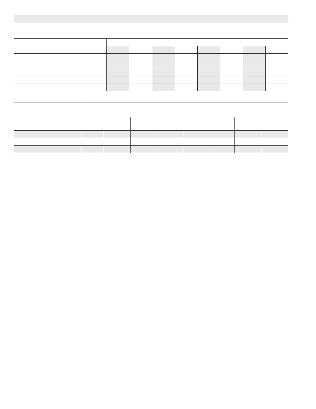
BLOWER DATA
SLP98DF110V60C BLOWER PERFORMANCE (less lter)
HEATING BLOWER PERFORMANCE
Heating Adjust CFM Selections
35% 40% 50% 60% 70% 80% 90% 100%
Increase (+15%) Heat CFM 8 11 906 1096 1286 1475 1665 1855 2045
Increase (+7.5%) Heat CFM 744 835 1017 1199 1380 1562 1744 1926
Default Heat CFM 677 764 938 1112 1285 1459 1633 1807
Decrease (-7.5% ) Heat CFM 626 707 869 1031 1193 1355 1517 1679
Decrease (-15% ) Heat CFM 575 650 800 950 1101 1251 1401 1551
COOLING BLOWER PERFORMANCE
Cooling Adjust CFM
Selections
First Stage Cool Speed - cfm Second Stage Cool Speed - cfm
Low Medium-
Low
Increase (+10%) Cool CFM 1090 1260 1395 1580 1580 1790 1990 2180
Default Cool CFM 965 1125 1285 1440 1440 1625 1845 2000
Decrease (-10%) Cool CFM 860 1030 1125 1270 1270 1470 1655 1845
The effect of static pressure is included in air volumes shown.
The following control congurations are available. See Installation Instructions for details and DIP switch settings.
Heat Modes Available (Heating Blower Performance Table):
Single stage thermostat:
- 35%, 70%, 100% input (three-stage) with time delays in-between
Two-stage thermostat:
- Variable Rate Capacity Mode - furnace automatically adjusts ring rate based on rst- and second-stage cycle times
- W1 demand at 70% input, W2 demand at 100% input. No delay between stages
icomfort Touch™ Communicating Thermostat:
- Variable Rate Capacity Mode - furnace automatically adjusts ring rate based on rst- and second-stage cycle times
- 35%, 60%, 80%, 100% (four-stage) with time delays in-between
Cool Mode Available (Cooling Blower Performance table):
First stage COOL (two-stage air conditioning units only) is approximately 70% of the same second stage COOL speed position.
Continuous Fan speeds are approximately 28%, 38%, 70% and 100% (DIP switch selectable) of the same second-stage COOL speed position
minimum 300 cfm.
Lennox Harmony III™ Zoning System Applications - Minimum blower speed is 450 cfm.
Heating Input Range and Blower Volume - CFM
Blower Speed Selections
Medium
High
High
(Default)
Low Medium-
Low
Medium
High
High
(Default)
Page 42
Page 43

TABLE 24
COOLING OPERATING SEQUENCE
SLP98DFV and Single−Stage Outdoor Unit
OPERATING
SEQUENCE
SYSTEM DEMAND SYSTEM RESPONSE
Demand Relative Humidity
System
Condition
Step
1st
stage
O G Status D*
NO CALL FOR DEHUMIDIFICATION
Normal Operation 1 On On On Acceptable
24
VAC
BASIC MODE (only active on a Y1 thermostat demand)
Normal Operation 1 On On On Acceptable
Dehumidification
Call
2 On On On Demand
24
VAC
0
VAC
PRECISION MODE (operates independent of a Y1 thermostat demand)
Normal Operation 1 On On On Acceptable
Dehumidification
call
Dehumidification
call ONLY
2 On On On Demand
1 On On On Demand
24
VAC
0
VAC
0
VAC
On−board links at indoor unit with a single−stage outdoor unit:
With Condensing unit − Cut W914 (R to DS) on SureLight
With Heat Pump − Cut W914 (R to DS) & W951 (R to O) on SureLight
control.
*ComfortSense
®
7000 thermostat ony
Compressor
High 100%
High 100%
High 70%
High 100%
High 70%
High 70%
®
control;
Blower
CFM
(COOL)
®
Comments
Compressor and indoor
blower follow thermostat
demand
Thermostat energizes Y1
and de−energizes D on a
call for de−humidification
Dehumidification mode
begins when humidity is
greater than set point
Thermostat will keep outdoor unit energized after
cooling temperature setpoint has been reached in
order to maintain room
humidity setpoint.
Page 43
Page 44

TABLE 25
COOLING OPERATING SEQUENCE
SLP98DFV and Two−Stage Outdoor Unit
OPERATING
SEQUENCE
SYSTEM DEMAND SYSTEM RESPONSE
Demand Relative Humidity
System
Condition
Step
1st
stage
2nd
stage
G
O
Status D*
NO CALL FOR DEHUMIDIFICATION
Normal Operation −
Y1
Normal Operation −
Y2
1 On On
2 On
On
On
On
On
Acceptable
Acceptable
24
VAC
24
VAC
ROOM THERMOSTAT CALLS FOR FIRST STAGE COOLING
BASIC MODE (only active on a Y1 thermostat demand)
Normal Operation 1 On On
Dehumidification
Call
2 On
On
On
On
On
Acceptable
Demand
24
VAC
0
VAC
PRECISION MODE (operates independent of a Y1 thermostat demand)
Normal Operation 1 On On
Dehumidification
call
Dehumidification
call ONLY
2 On
1 On
On
On
On
On
On
On
On
Acceptable
Demand
Demand
24
VAC
0
VAC
0
VAC
ROOM THERMOSTAT CALLS FOR FIRST AND SECOND STAGE COOLING
BASIC MODE (only active on a Y1 thermostat demand)
Normal Operation 1 On
Dehumidification
Call
2 On
On
On
On
On
On
On
Acceptable
Demand
24
VAC
0
VAC
PRECISION MODE (operates independent of a Y1 thermostat demand)
Normal Operation 1 On On
Dehumidification
call
2 On
On
On
On
On
Acceptable
Demand
24
VAC
0
VAC
Compressor
Low 70%
High 100%
Low 70%
High 70%
Low 70%
High 70%
High 70%
High 100%
High 70%
Low 70%
High 70%
Blower
CFM
(COOL)
Comments
Compressor and indoor
blower follow thermostat
demand
Thermostat energizes
2nd stage and de−energizes D on a call for de−
humidification
Dehumidification mode
begins when humidity is
greater than set point
Thermostat will keep outdoor unit energized after
cooling temperature setpoint has been reached
in order to maintain room
humidity setpoint.*
Thermostat energizes
2nd stage and de−energizes D on a call for de−
humidification
Dehumidification mode
begins when humidity is
greater than set point
Dehumidification
call ONLY
1 On
On
On
On
Demand
On−board links at indoor unit with a two−stage outdoor unit:
Cut factory link from Y1 to Y2 or cut W915 (Y1 to Y2) on SureLight
grated control.
With Condensing unit − Cut W914 (R to DS) on SureLight
0
VAC
High 70%
®
®
integrated control;
With Heat Pump − Cut W914 (R to DS) & W951 (R to O) on SureLight
integrated control.
*ComfortSense
®
7000 thermostat only
Page 44
inte-
®
Thermostat will keep outdoor unit energized after
cooling temperature setpoint has been reached
in order to maintain room
humidity setpoint.
Page 45

Unit Start−Up
FOR YOUR SAFETY READ BEFORE OPERATING
WARNING
Do not use this furnace if any part has been underwater. A flood−damaged furnace is extremely dangerous. Attempts to use the furnace can result in
fire or explosion. Immediately call a qualified service technician to inspect the furnace and to replace
all gas controls, control system parts, and electrical
parts that have been wet or to replace the furnace,
if deemed necessary.
WARNING
Danger of explosion. Can cause injury
or product or property damage. Should
the gas supply fail to shut off or if
overheating occurs, shut off the gas
valve to the furnace before shutting off
the electrical supply.
CAUTION
Before attempting to perform any service or maintenance, turn the electrical power to unit OFF at disconnect switch.
WARNING
During blower operation, the ECM motor emits energy that may interfere with pacemaker operation. Interference is reduced by both the sheet metal cabinet
and distance.
Priming Condensate Trap
The condensate trap should be primed with water prior to
start−up to ensure proper condensate drainage. Either
pour 10 fl. oz. (300 ml) of water into the trap, or follow
these steps to prime the trap:
1 − Follow the lighting instructions to place the unit into op-
eration.
2 − Set the thermostat to initiate a heating demand.
3 − Allow the burners to fire for approximately 3 minutes.
4 − Adjust the thermostat to deactivate the heating de-
mand.
5 − Wait for the combustion air inducer to stop. Set the
thermostat to initiate a heating demand and again allow the burners to fire for approximately 3 minutes.
6 − Adjust the thermostat to deactivate the heating de-
mand and again wait for the combustion air inducer to
stop. At this point, the trap should be primed with sufficient water to ensure proper condensate drain operation.
BEFORE BEFORE PLACING THE UNIT INTO OPERATION, smell all around the furnace area for gas. Be sure
to smell next to the floor because some gas is heavier
than air and will settle on the floor.
The gas valve on the SLP98DFV is equipped with a gas
control switch. Use only your hand to move the control
switch. Never use tools. If the switch will not move by
hand, do not try to repair it. Force or attempted repair may
result in a fire or explosion.
Placing the furnace into operation:
SLP98DFV units are equipped with an automatic ignition
system. Do not attempt to manually light burners on this
furnace. Each time the thermostat calls for heat, the
burners will automatically light. The ignitor does not get
hot when there is no call for heat on units with this ignition
system.
WARNING
If you do not follow these instructions exactly, a fire
or explosion may result causing property damage,
personal injury or death.
Gas Valve Operation (Figure 45)
1 − STOP! Read the safety information at the beginning of
this section.
2 − Set the thermostat to the lowest setting.
3 − Turn off all electrical power to the unit.
4 − This furnace is equipped with an ignition device which
automatically lights the burners. Do not try to light the
burners by hand.
5 − Remove the access panel.
6 − Move the gas valve switch to the OFF position. See
figure 45.
7 − Wait five minutes to clear out any gas. If you then smell
gas, STOP! Immediately call the gas supplier from a
neighbor’s phone. Follow the gas supplier’s instructions. If you do not smell gas go to next step.
8 − Move gas valve switch to the ON position. See figure
45. Do not force.
NEGATIVE AIR
PRESSURE PORT
INLET
SUPPLY
PRESSURE
TAP
GAS VALVE SHOWN IN THE ON POSITION
GAS VALVE
POSITIVE AIR
PRESSURE PORT
OUTLET
MANIFOLD
PRESSURE TAP
FIGURE 45
Page 45
Page 46

9 − Replace the access panel.
10− Turn on all electrical power to to the unit.
11− Set the thermostat to desired setting.
NOTE − When unit is initially started, steps 1 through 11
may need to be repeated to purge air from gas line.
12− If the appliance will not operate, follow the instructions
Turning Off Gas to Unit" and call the gas supplier.
Turning Off Gas to Unit
1 − Set the thermostat to the lowest setting.
2 − Turn off all electrical power to the unit if service is to be
performed.
3 − Remove the access panel.
4 − Move the gas valve switch to the OFF position.
5 − Replace the access panel.
Failure To Operate
If the unit fails to operate, check the following:
1 − Is the thermostat calling for heat?
2 − Are access panels securely in place?
3 − Is the main disconnect switch closed?
4 − Is there a blown fuse?
5 − Is the filter dirty or plugged? Dirty or plugged filters will
cause the limit control to shut the unit off.
6 − Is gas turned on at the meter?
7 − Is the manual main shut-off valve open?
8 − Is the gas valve turned on?
9 − Is the unit ignition system in lock out? If the unit locks out
again, inspect the unit for blockages.
10 − Is blower harness connected to ignition control? Fur-
nace will not operate unless harness is connected.
High Altitude Information
NOTE − In Canada, certification for installations at elevations over 4500 feet (1372 m) is the jurisdiction of local authorities.
TABLE 27
Conversion Kit Requirements and Manifold Test Pressures
SLP98DFV units require no manifold pressure adjustments for operation at altitudes up to 10,000 feet (3048 m)
above sea level. Units installed at altitude of 7,501 to
10,000 feet (2287 to 3048m) require a pressure switch
change per table 27. Table 27 lists conversion kit requirements and manifold pressures at all altitudes.
The combustion air pressure switch is factory−set and requires no adjustment.
NOTE − A natural to LP/propane gas changeover kit is necessary to convert this unit. Refer to the changeover kit
installation instruction for the conversion procedure.
Gas Pressure Measurement
Gas Flow (Approximate)
TABLE 26
GAS METER CLOCKING CHART
Seconds for One Revolution
SLP98
Unit
−070 55 110 136 272
−090 41 82 102 204
−110 33 66 82 164
−135 27 54 68 136
Natural−1000 btu/cu ft LP−2500 btu/cu ft
Furnace should operate at least 5 minutes before checking gas flow. Determine time in seconds for two revolu-
tions of gas through the meter. (Two revolutions assures a
more accurate time.) Divide by two and compare to time
in table 26 below. If manifold pressure matches table 27
and rate is incorrect, check gas orifices for proper size and
restriction. Remove temporary gas meter if installed.
NOTE − To obtain accurate reading, shut off all other gas
appliances connected to meter.
Supply Pressure Measurement
A threaded plug on the inlet side of the gas valve provides
access to the supply pressure tap. Remove the threaded
plug, install a field−provided barbed fitting and connect a
manometer to measure supply pressure. Replace the
threaded plug after measurements have been taken.
Natural LP
1 cu ft
Dial
2 cu ft
Dial
1 cu ft
Dial
2 cu ft
DIAL
LP/Propane
Model
Input
Size
−070
−090
−110
NOTE − The values given in table 27 are measurements only. The gas valve should not be adjusted.
Kit
0 − 10,000
(0 − 3048 m)
65W77 Not required 74W37 0.40 − 0.60 1.2 − 1.8 3.2 − 3.8 9.5 − 10.5 .0625 .034
High Altitude Pressure
Switch Kit
0 − 7,500
(0 − 2286 m)
7,501 − 10,000
(2287 −
3048m)
Manifold Pressure at All Altitudes (in. w.g.)
Low Fire
(35% rate)
Natural Gas LP/Propane Natural Gas LP/Propane Nat LP
Page 46
High Fire
(100% rate)
Gas Orifice Size
Page 47

Proper Combustion
Furnace should operate minimum 15 minutes with correct
manifold pressure and gas flow rate before checking combustion. Take combustion sample beyond the flue outlet
and compare to the tables below. The maximum carbon
monoxide reading should not exceed 50 ppm.
TABLE 28
High Fire
SLP98DFV Unit CO2%
For Nat
CO2%
For L.P.
070V36B
090V36C
090V60C
7.6 − 8.6 9,1 − 10.1
110V60C
TABLE 29
Low Fire
Unit CO2%
For Nat
CO2%
For L.P.
070V36B
090V36C
090V60C
5.3 − 6.3 6.8 − 7.8
110V60C
Manifold Pressure Measurement
To correctly measure manifold pressure, the differential
pressure between the positive gas manifold and the negative burner box must be considered. Use pressure test
adapter kit (available as Lennox part 10L34) to assist in
measurement.
1 − Remove the threaded plug from the outlet side of the
gas valve and install a field−provided barbed fitting.
Connect test gauge +" connection to barbed fitting to
measure manifold pressure.
2 − Tee into the gas valve regulator vent hose and connect
test gauge −" connection.
3 − Start unit on low heat (35% rate) and allow 5 minutes
for unit to reach steady state.
4 − While waiting for the unit to stabilize, notice the flame.
Flame should be stable and should not lift from burner.
Natural gas should burn blue.
5 − After allowing unit to stabilize for 5 minutes, record
manifold pressure and compare to value given in table
27.
6 − Repeat steps 3, 4 and 5 on high heat.
NOTE − Shut unit off and remove manometer as soon as an
accurate reading has been obtained. Take care to remove
barbed fitting and replace threaded plug.
CAUTION
Do not attempt to make adjustments to the gas valve.
Other Unit Adjustments
Primary Limit
The primary limit is located on the heating compartment
vestibule panel. This limit is factory set and require no adjustment.
Flame Rollout Switches (Two)
These manually reset switches are located on the burner
box.
Pressure Switches (Two)
The pressure switches are located in the heating compartment on the combustion air inducer. These switches check
for proper combustion air inducer operation before allowing ignition trial. The switches are factory−set and require
no adjustment. Pressure switch tubing installation is critical
for safe operation. See figure 46.
PRESSURE SWITCH TUBING INSTALLATION
4
High−Fire
Pressure
Switch
Cold End
Header Box
Low−Fire
Pressure
Switch
Gas Valve
1 − Black hose from front port on low−fire pressure switch to
positive port on the gas valve.
2 − Red hose from rear port on low−fire pressure switch to the
negative port on the gas valve.
3 − Red hose from front port on high−fire pressure switch to
negative port on cold end header box.
4 − Black hose from rear port on high−fire pressure switch to
positive port on cold end header box.
FIGURE 46
3
2
1
Page 47
Page 48

Temperature Rise
After the furnace has been started and supply and return air
temperatures have been allowed to stabilize, check the
temperature rise with the unit operating at 100 percent firing rate. If necessary, adjust the blower speed to maintain
the temperature rise within the range shown on the unit
nameplate. Increase the blower speed to decrease the
temperature. Decrease the blower speed to increase the
temperature rise. Failure to adjust the temperature rise
may cause erratic limit operation.
Thermostat Heat Anticipation
Set the heat anticipator setting (if adjustable) according to
the amp draw listed on the wiring diagram that is attached
to the unit.
Electrical
1 − Check all wiring for loose connections.
2 − Check for the correct voltage at the furnace (furnace
operating).Correct voltage is 120VAC + 10%.
3 − Check amp−draw on the blower motor with inner
blower panel in place.
Motor Nameplate__________Actual__________
Electronic Ignition
The integrated control has an added feature of an internal
Watchguard control. The feature serves as an automatic reset device for ignition control lockout caused by ignition failure. This type of lockout is usually due to low gas line pressure. After one hour of continuous thermostat demand for
heat, the Watchguard will break and remake thermostat demand to the furnace and automatically reset the control to
begin the ignition sequence.
Exhaust and Air Intake Pipe
1 − Check exhaust and air intake connections for tightness
and to make sure there is no blockage.
2 − Are pressure switches closed? Obstructed exhaust
pipe will cause unit to shut off at pressure switches.
Check termination for blockages.
3 − Reset manual flame rollout switches on burner box
cover.
Heating Sequence of Operation
The integrated control initiates a pressure switch calibration at the initial unit start−up on a call for heat. The ignition
control will also initiate a calibration any time main power is
turned off and back on and a heating demand is present .
Additional calibrations may be initiated by the service technician during field test sequence. The following heating sequence of operation assumes completion of a successful
calibration.
NOTE − The thermostat selection DIP switch on the integrated
control is factory−set in the TWO−STAGE" position.
Applications Using a Two−Stage Thermostat
A − Heating Sequence −− Control Thermostat Selection
DIP switch in Two−Stage" Position (Factory Setting)
1 − On a call for heat, thermostat first−stage contacts close
sending a signal to the integrated control. The integrated control runs a self-diagnostic program and
checks high temperature limit switches for normally
closed contacts and pressure switches for normally
open contacts. The combustion air inducer is energized at ignition speed, which is approximately the
same as the inducer speed at 70 percent firing rate.
2 − Once the control receives a signal that the low−fire
pressure switch has closed, the combustion air inducer begins a 15−second pre−purge in the ignition speed.
3 − After the pre−purge is complete, a 20−second initial ig-
nitor warm−up period begins. The combustion air inducer continues to operate at the ignition speed.
4 − After the 20−second warm−up period has ended, the gas
valve is energized and ignition occurs. At the same time,
the control module sends a signal to begin an indoor
blower 45−second ON delay. When the delay ends, the
indoor blower motor is energized at a speed that
matches the firing rate. After the 10−second ignition
stabilization delay expires, the inducer speed is adjusted to the appropriate target rate. The inducer will
remain at the 70 percent speed as long as the thermostat has a first−stage heating demand.
5 − If second−stage heat is required, the thermostat sec-
ond−stage heat contacts close and send a signal to the
integrated control. The integrated control initiates a
30−second second−stage recognition delay.
6 − At the end of the recognition delay and for all subse-
quent calls for second−stage heat, the integrated control energizes the combustion air inducer at high
speed. The control also checks the high−fire pressure
switch to make sure it is closed. As the inducer speed
is increased to high, the indoor blower motor is adjusted to a speed which is appropriate for second−
stage heat.
7 − When the demand for high−fire (second stage) heat is
satisfied, the gas valve is de−energized and the field−
selected indoor blower off delay begins. The combustion air inducer begins a 20−second post−purge period.
8 − When the combustion air post−purge period is com-
plete, the inducer is de−energized. The indoor blower
is de−energized at the end of the off delay.
Applications Using a Two−Stage Thermostat
B − Heating Sequence −− Control Thermostat Selection
DIP switch in Variable Capacity" Position
1 − On a call for heat, thermostat first−stage contacts close
sending a signal to the integrated control. The integrated control runs a self-diagnostic program and
checks high temperature limit switches for normally
Page 48
Page 49

closed contacts and pressure switches for normally
open contacts. The combustion air inducer is energized at ignition speed, which is approximately the
same as the inducer speed at 70 percent firing rate.
2 − Once the control receives a signal that the low−fire
pressure switch has closed, the combustion air inducer begins a 15−second pre−purge in low speed.
3 − After the pre−purge is complete, a 20−second initial ig-
nitor warm−up period begins. The combustion air inducer continues to operate at the ignition speed.
4 − After the 20−second warm−up period has ended, the gas
valve is energized and ignition occurs. At the same time,
the control module begins an indoor blower 45−second
ON delay. When the delay ends, the indoor blower motor is energized at a speed that matches the firing rate.
After the 10−second ignition stabilization delay expires, the inducer speed is adjusted to the appropriate
target rate. If the furnace is operating in the initial heating cycle after power−up, the initial firing rate will be
approximately 35 percent. The firing rate on subsequent cycles will be automatically adjusted by the integrated control based on thermostat cycles. The firing
rate will vary and will range from 35 percent to 90 percent. The furnace will continue this operation as long
as the thermostat has a first−stage heating demand.
5 − If second−stage heat is required, the thermostat sec-
ond−stage heat contacts close and send a signal to the
integrated control. The integrated control either increases the firing rate to 70 percent (if the current rate
is at or below 60 percent) or increases the firing rate
by 10 percent (if the current rate is above 60 percent).
If the call for heat continues 5 minutes beyond this initial upstage, the rate will be increased by 10 percent
every 5 minutes until the call for heat is satisfied or the
furnace reaches 100 percent rate. As the firing rate increases, the indoor blower motor is adjusted to a
speed which is appropriate for the target rate.
6 − If second−stage heat demand is satisfied, but first
stage is still present, the furnace will continue to operate at the present firing rate until the heat cycle ends.
7 − When the demand for first− and second−stage heat is
satisfied, the gas valve is de−energized and the field−
selected indoor blower off delay begins. The combustion air inducer begins a 20−second post−purge period.
8 − When the combustion air post−purge period is com-
plete, the inducer is de−energized. The indoor blower
is de−energized at the end of the off delay.
Applications Using A Single−Stage Thermostat
C − Heating Sequence −− Control Thermostat Selection
DIP switch in Single−Stage" Position
1 − On a call for heat, thermostat first−stage contacts close
sending a signal to the integrated control. The integrated control runs a self-diagnostic program and
checks high temperature limit switches for normally
closed contacts and pressure switches for normally
open contacts. The combustion air inducer is energized at the ignition speed, which is approximately the
same as the inducer speed at 70 percent firing rate.
2 − Once the control receives a signal that the low−fire
pressure switch has closed, the combustion air inducer begins a 15−second pre−purge at the ignition speed.
3 − After the pre−purge is complete, a 20−second initial ig-
nitor warm−up period begins. The combustion air inducer continues to operate at the ignition speed.
4 − After the 20−second warm−up period has ended, the gas
valve is energized and ignition occurs, which initiates a
10−second ignition stabilization delay. At the same time,
the control module sends a signal to begin an indoor
blower 45−second ON delay. When the delay ends, the
indoor blower motor is energized at a speed which is
appropriate for the firing rate. After the 10−second ignition stabilization delay expires, the inducer speed is
adjusted to 35 percent speed. The integrated control
also initiates a second−stage on delay (factory−set at
7 minutes; adjustable to 12 minutes).
5 − If the heating demand continues beyond the second−
stage on delay, the integrated control energizes the
combustion air inducer at 70 percent speed. The indoor blower motor is adjusted to a speed which
matches the target rate. A fixed, 10−minute third−stage
on delay is initiated.
6 − If the heating demand continues beyond the third−
stage on delay, the integrated control energizes the inducer at high speed. The indoor blower motor is adjusted to a speed which is appropriate for the target
rate.
7 − When the thermostat heating demand is satisfied, the
gas valve is de−energized and the combustion air inducer begins a 20−second post−purge. The field−selected indoor blower off delay begins.
8 − When the combustion air post−purge period is com-
plete, the inducer is de−energized. The indoor blower
is de−energized at the end of the off delay.
Page 49
Page 50

Service
WARNING
ELECTRICAL SHOCK, FIRE,
OR EXPLOSION HAZARD.
Failure to follow safety warnings exactly could result
in dangerous operation, serious injury, death or
property damage.
Improper servicing could result in dangerous operation, serious injury, death, or property damage.
Before servicing, disconnect all electrical power to
furnace.
When servicing controls, label all wires prior to disconnecting. Take care to reconnect wires correctly.
Verify proper operation after servicing.
At the beginning of each heating season, system should be
checked as follows by a qualified service technician:
Blower
Check the blower wheel for debris and clean if necessary.
The blower motors are prelubricated for extended bearing
life. No further lubrication is needed.
WARNING
The blower access panel must be securely in place
when the blower and burners are operating. Gas
fumes, which could contain carbon monoxide, can
be drawn into living space resulting in personal injury or death.
Filters
All SLP98DFV filters are installed external to the unit. Filters should be inspected monthly. Clean or replace the filters when necessary to ensure proper furnace operation.
Table 3 lists recommended filter sizes.
Exhaust and air intake pipes
Check the exhaust and air intake pipes and all connections
for tightness and to make sure there is no blockage.
NOTE − After any heavy snow, ice or frozen fog event the
furnace vent pipes may become restricted. Always check
the vent system and remove any snow or ice that may be
obstructing the plastic intake or exhaust pipes.
Electrical
1 − Check all wiring for loose connections.
2 − Check for the correct voltage at the furnace (furnace
operating).
3 − Check amp−draw on the blower motor.
Motor Nameplate__________Actual__________
Winterizing and Condensate Trap Care
1 − Turn off power to the unit.
2 − Have a shallow pan ready to empty condensate water.
3 − Remove the drain plug from the condensate trap and
empty water. Inspect the trap then reinstall the drain
plug and refill trap with water.
Cleaning Heat Exchanger
If cleaning the heat exchanger becomes necessary, follow
the below procedures and refer to figure 1 when disassembling unit. Use papers or protective covering in front of furnace while removing heat exchanger assembly.
1 − Turn off electrical and gas supplies to the furnace.
2 − Remove the furnace access panels.
3 − Disconnect the 2−pin plug from the gas valve.
4 − Remove gas supply line connected to gas valve. Re-
move the burner box cover and remove gas valve/
manifold assembly.
5 − Remove sensor wire from sensor. Disconnect 2-pin
plug from the ignitor.
6 − Disconnect wires from flame roll−out switches.
7 − Loosen clamps at vent elbow. Disconnect condensate
drain tubing from flue collar. and remove the vent el-
bow.
8 − Remove four burner box screws at the vestibule panel
and remove burner box. Set burner box assembly
aside.
NOTE − If necessary, clean burners at this time. Follow
procedures outlined in Burner Cleaning section.
9 − Mark and disconnect all combustion air pressure tub-
ing from cold end header collector box.
10 − Mark and remove wires from pressure switches. Re-
move pressure switches. Keep tubing attached to
pressure switches
11 − Disconnect the 4-pin plug from the combustion air in-
ducer. Remove two screws which secure combustion
air inducer to collector box. Remove combustion air in-
ducer assembly. Remove ground wire from vest pan-
el.
12 − Remove electrical junction box from the side of the fur-
nace.
13 − Remove cold end header box.
14 − Mark and disconnect any remaining wiring to heating
compartment components. Disengage strain relief
bushing and pull wiring and bushing through the hole in
the blower deck.
15 − Remove the primary limit from the vestibule panel.
16 − Remove two screws from the front cabinet flange at
the blower deck. Spread cabinet sides slightly to allow
clearance for removal of heat exchanger.
17 − Remove screws along vestibule sides which secure
vestibule panel and heat exchanger assembly to cabi-
net. Remove two screws from blower rail which secure
bottom heat exchanger flange. Remove heat ex-
changer from furnace cabinet.
18 − Back wash heat exchanger with soapy water solution
or steam. If steam is used it must be below 275°F
(135°C) .
Page 50
Page 51

19 − Thoroughly rinse and drain the heat exchanger. Soap
solutions can be corrosive. Take care to rinse entire
assembly.
20 − Reinstall heat exchanger into cabinet making sure that
the clamshells of the heat exchanger assembly are
resting on the support located at the rear of the cabinet. Remove the indoor blower to view this area
through the blower opening.
21 − Re-secure the supporting screws along the vestibule
sides and top to the cabinet.
22 − Reinstall cabinet screws on front flange at blower
deck.
23 − Reinstall the primary limit on the vestibule panel.
24 − Route heating component wiring through hole in blow-
er deck and reinsert strain relief bushing.
25 − Reinstall electrical junction box.
26 − Reinstall the cold end header box.
27 − Reinstall the combustion air inducer. Reconnect the
combustion air inducer to the wire harness.
28 − Reinstall pressure switches and reconnect pressure
switch wiring.
29 − Carefully connect combustion air pressure switch
hosing from pressure switches to proper stubs on
cold end header collector box.
30 − Reinstall condensate trap.
31 − Reinstall burner box assembly in vestibule area.
32 − Reconnect exhaust piping and exhaust drain tubing.
33 − Reconnect flame roll−out switch wires.
34 − Reconnect sensor wire and reconnect 2−pin plug from
ignitor.
35 − Secure burner box assembly to vestibule panel using
four existing screws. Make sure burners line up in
center of burner ports.
36 − Reinstall gas valve manifold assembly. Reconnect
gas supply line to gas valve.
37 − Reinstall burner box cover.
38 − Reconnect 2−pin plug to gas valve.
39 − Replace the blower compartment access panel.
40 − Refer to instruction on verifying gas and electrical con-
nections when re−establishing supplies.
41 − Follow lighting instructions to light and operate fur-
nace for 5 minutes to ensure that heat exchanger is
clean and dry and that furnace is operating properly.
42 − Replace heating compartment access panel.
Cleaning the Burner Assembly
1 − Turn off electrical and gas power supplies to furnace.
Remove upper and lower furnace access panels.
2 − Disconnect the 2−pin plug from the gas valve.
3 − Remove the burner box cover.
4 − Disconnect the gas supply line from the gas valve. Re-
move gas valve/manifold assembly.
5 − Mark and disconnect sensor wire from the sensor. Dis-
connect 2-pin plug from the ignitor at the burner box.
6 − Remove four screws which secure burner box assem-
bly to vest panel. Remove burner box from the unit.
7 − Use the soft brush attachment on a vacuum cleaner to
gently clean the face of the burners. Visually inspect
the inside of the burners and crossovers for any block-
age caused by foreign matter. Remove any blockage.
8 − Reconnect the sensor wire and reconnect the 2−pin
plug to the ignitor wiring harness.
9 − Reinstall the burner box assembly using the existing
four screws. Make sure that the burners line up in the
center of the burner ports.
10 − Reinstall the gas valve manifold assembly. Reconnect
the gas supply line to the gas valve. Reinstall the burn-
er box cover.
11 − Reconnect 2−pin plug to gas valve.
12 − Replace the blower compartment access panel.
13 − Refer to instruction on verifying gas and electrical con-
nections when re−establishing supplies.
14 − Follow lighting instructions to light and operate fur-
nace for 5 minutes to ensure that heat exchanger is
clean and dry and that furnace is operating properly.
15 − Replace heating compartment access panel.
Page 51
Page 52

Planned Service
A service technician should check the following items during an annual inspection. Power to the unit must be shut off
for the service technician’s safety.
Burners − Must be inspected for rust, dirt, or signs of water.
Return air duct − Must be properly attached and provide
an air seal to the unit.
Operating performance − Unit must be observed during
operation to monitor proper performance of the unit and the
vent system.
Vent pipe − Must be inspected for signs of water, cracked,
damaged or sagging pipe, or disconnected joints.
Unit appearance − Must be inspected for rust, dirt, signs
of water, burnt or damaged wires, or components.
Blower access door − Must be properly in place and provide a seal between the return air and the room where the
furnace is installed.
Combustion gases − Flue products must be analyzed and
compared to the unit specifications.
Problems detected during the inspection may make it necessary to temporarily shut down the furnace until the items
can be repaired or replaced.
Instruct the homeowners to pay attention to their
furnace. Situations can arise between annual furnace in-
spections that may result in unsafe operation.
Page 52
Page 53

Integrated Control Diagnostic Codes
Press the diagnostic push button and hold it to cycle through a menu of options. Every five seconds a new menu item will be displayed.
Release the button when the desired mode is displayed.
When a solid "P" is displayed, the furnace capacity/ size is programmed.
When the solid E" is displayed, the control enters the Error Code Recall mode. Error Code Recall mode menu options: No change (displaying error history) remains in Error Code Recall mode; solid b" exits Error Code Recall mode; and solid c" clears the error history. Must
press button while flashing c" is displayed to clear error codes.
When the solid −" is displayed, the control enters the Field Test mode. Field Test mode menu options: Solid C" starts pressure switch
calibration; blinking −" exits Field Test mode.
Code Diagnostic Codes/Status of Equipment Action Required to Clear and Recover
. Idle mode (Decimal blinks at 1 Hertz −− 0.5 second ON, 0.5 second OFF).
A
C
d
h
H
df
E 105
E 110
E 113
E 114
E 115
E 120
E 124
E 125
E 126
E 131
E 180
E 200
E 201
E 202
E 203
E 204
E 205
E 207
Cubic feet per minute (cfm) setting for indoor blower (1 second ON, 0.5 second
OFF) / cfm setting for current mode displayed.
Cooling stage (1 second ON, 0.5 second OFF) / 1 or 2 displayed / Pause / cfm
setting displayed / Pause / Repeat codes).
Dehumidification mode (1 second ON) / 1 second OFF) / cfm setting displayed /
Pause / Repeat Codes).
Variable Capacity Heat (1 second ON, 0.5 second OFF) / % of input rate displayed
/ Pause/ cfm setting / Pause/ Repeat codes.
Heat Stage (1 second ON, 0.5 second OFF) / 1 or 2 displayed / Pause / cfm setting displayed / Pause / Repeat codes.
Defrost mode.
Device communication problem − No other devices on BUS (Communication
system).
Low line voltage. Line Voltage low (Voltage lower than nameplate rating)
High line voltage. Line Voltage High (Voltage higher than nameplate rating)
Line voltage frequency out−of−range. No 60 hertz power (Check voltage and frequency).
Low 24V − Control will restart if the error recovers. 24 voltage low (Range is 18 to 30 volts) Check voltage.
Unresponsive device. Usually caused by delay in outdoor unit responding to
Active communicating thermostat signal missing for more than 3 minutes. Equipment lost communication with the thermostat. Check
Control failed self−check, internal error, failed hardware. Will restart if error
recovers. Integrated furnace control not communicating. Covers hardware errors
(flame sense circuit faults, pin shorts, etc.).
Failed internal control communication between microcontrollers. Hardware problem on the control board. Cycle power on
Corrupted control parameters (Verify configuration of system). Reconfigure the system. Replace board if service (heating
Outdoor air sensor failure − NO error if disconnected. Only shown if shorted or
out−of−range.
Hard lockout − Rollout circuit open or previously open. Correct unit cause of rollout trip or replace flame rollout
Indoor blower communication failure − Unable to communicate with blower motor. Indoor blower communication failure including power
Indoor blower motor mis−match − Indoor motor horsepower does not match unit
capacity.
Appliance capacity / size is NOT programmed. Invalid unit codes refer to
configuration flow chart in installation instructions.
Gas valve mis−wired. Check operation of gas valve.
Gas valve control relay contact shorted. Check operation of gas valve.
Hot surface ignitor sensed open − Refer to troubleshooting in installation
instruction.
Equipment is unable to communicate. Check for mis wire
and loose connections and check for a high voltage source
of noise close to the system. (welder etc.).
Check voltage.
Check voltage.
indoor unit poling recycle power, check wiring.
connections and cycle power on the thermostat.
Hardware problem on the control board. Cycle power on
control. Replace if problem prevents service and is
persistent.
control. Replace if problem prevents service and is
persistent.
/cooling) is unavailable.
Compare outdoor sensor resistance to temperature
resistance charts in installation instructions. Replace if
necessary.
switch and test furnace operation.
outage.
Incorrect furnace size code selected. Check unit size
codes on configuration guide or in installation instructions.
No furnace size code selected. Check unit size codes on
configuration guide or in installation instructions.
Measure resistance of Hot Surface Ignitor, replace if open
or not within specification.
Page 53
Page 54

Integrated Control Diagnostic Codes (continued)
Code Diagnostic Codes/Status of Equipment Action Required to Clear and Recover
E 223
E 224
E 225
E 226
E 227
E 228
E 240
E 241
E 250
E 252
E 270
E 271
E 272
E 273
E 274
E 275
E 276
E 290
E 291
E 292
E 294
Low pressure switch failed open − Refer to troubleshooting in installation
instruction.
Low pressure switch failed closed − Refer to troubleshooting in installation
instruction.
High pressure switch failed open − Refer to troubleshooting in installation
instruction.
High pressure switch failed closed − Refer to troubleshooting in installation
instruction.
Low pressure switch open during trial for ignition or run mode. Refer to troubleshooting in installation instruction.
Unable to perform successful pressure switch calibration. Retry after 300 seconds. Error counter cleared when exit-
Low flame current − Run mode − Refer to troubleshooting in
installation instruction.
Flame sensed out of sequence − Flame still present. Shut off gas, check for gas valve leak.
Limit switch circuit open − Refer to troubleshooting in installation instruction. Check why limit is tripping, overfired, low air flow.
Discharge air temperature too high (gas heat only). Check temperature rise, air flow and input rate.
Soft lockout − Exceeded maximum number of retries. No flame current sensed. Check for gas flow, ignitor lighting burner, flame sensor
Soft lockout − Exceeded maximum number of retries. Last retry failed due to
the pressure switch opening.
Soft lockout − Exceeded maximum number of recycles. Last recycle due to the
pressure switch opening.
Soft lockout − Exceeded maximum number of recycles. Last recycle due to
flame failure.
Soft lockout − Exceeded maximum number of recycles. Last recycle failed due
to the limit circuit opening or limit remained open longer than 3 minutes.
Soft lockout − Flame sensed out of sequence from code 241 fault. Flame signal
is gone.
Soft lockout − Exceeded maximum number of calibration retries. See E 228.
Ignitor circuit fault − Failed ignitor or triggering circuitry. See E 207.
Restricted air flow − Cubic feet per minute is lower than what is needed for
minimum firing rate.
Indoor blower motor unable to start − Seized bearings, stuck wheel, etc. Indoor blower motor unable to start (seized
Combustion air inducer motor amp draw is too high. Check combustion blower bearings, wiring , amperes,
Check inches of water column pressure during operation
of low pressure switch on heat call, measure inches of
water column of operating pressure, inspect vent and
combustion air inducer for correct operation and restriction.
Check low pressure switch for closed contacts, measure
inches of water column of operating pressure, inspect vent
and combustion air inducer for correct operation and restriction.
Check inches of water column pressure of high pressure
switch on heat call, measure inches of water column of
operating pressure, inspect vent and combustion air
inducer for correct operation and restriction.
Check high pressure switch for closed contacts, measure
inches of water column of operating pressure, inspect vent
and combustion air inducer for correct operation and
restriction.
Check inches of water column pressure during operation
of low pressure switch on heat call, measure inches of
water column of operating pressure, inspect vent and
combustion air inducer for correct operation and restriction.
ing lockout, unable to perform pressure switch calibration.
Check vent system and pressure switch wiring
connections.
Check micro amperes of flame sensor, clean or replace
sensor. Measure voltage of neutral to ground for good unit
ground.
current.
See E 223.
See E 223 and E 225.
See E 240.
See E 250.
See E 241.
Check for dirty filter, unit air flow restriction, blower
performance.
bearing, stuck wheel, etc), replace motor or wheel if
assembly does not operate or meet performance.
replace if it does not operate or meet performance.
Page 54
Page 55

Integrated Control Diagnostic Codes (continued)
Code Diagnostic Codes/Status of Equipment Action Required to Clear and Recover
E 295
E 310
E 311
E 312
E 313
E 331
E 347
E 348
E 349
E 401
E 402
E 403
E 404
E 405
E 406
E 407
E 408
E 409
Indoor blower motor temperature is too high. Indoor blower motor over temperature (motor
Discharge error sensor failure − No error if disconnected. Only shown if
shorted or out−of−range.
Heat rate reduced to match indoor blower air flow. Replace filter or repair
duct restriction.
Restricted air flow in cooling or continuous fan mode is lower than cfm
setting.
Indoor or outdoor unit capacity mismatch. Incorrect Indoor /outdoor capacity code selected.
Global network connection − Communication link problem. For Future Use.
No 24 Volt output on Y1 to C with non−communicating outdoor unit. Y1 relay / Stage 1 failed (Pilot relay contacts did not
No 24 Volt output on Y2 to C with non−communicating outdoor unit. Y2 relay / Stage 2 failed (Pilot relay contacts did not
No 24 Volts between R & O with non−communicating outdoor unit (Dual
fuel module required for heat pump application).
LSOM − Compressor ran more than 18 hours in air conditioning mode. Compressor protector is open. Check for high head
LSOM − Outdoor unit system pressure trip. Compressor ran over 18 hours in air conditioning
LSOM − Compressor short−cycling (Running less than 4 minutes). Outdoor unit pressure trip. Check dirty coil, fan mo-
LSOM − Compressor rotor locked. Compressor short cycling (Running less than 4 min-
LSOM − Compressor open circuit. Check capacitor, wiring, hard start kit , replace com-
LSOM − Compressor open start circuit. Check compressor for hot (cool down) , check pres-
LSOM − Compressor open run circuit.
LSOM − Compressor contactor is welded.
LSOM − Compressor low voltage. Replace contactor.
tripped on internal protector), Check motor bearings, amperes. Replace if necessary.
Discharge air temperature(DATS) out of range,
code is activated during "Field test mode".
Furnace blower in cutback mode due to restricted
airflow. Check filter and ductwork. To clear replace
filter if needed or repair/ add ductwork.
Restricted airflow − Indoor blower is running at a
reduced cubic feet per minute (Cutback Mode) −
The variable speed motor has pre−set speed and
torque limiters to protect the motor from damage
caused by operating out of its designed parameters
(0 to 0.8 inches water column total external static
pressure). Check filter and ductwork. To clear replace filter if needed or repair/ add ductwork.
Check for proper configuration in installation instructions. Alarm is just a warning. The system operation
is not impacted at all and alarm would clear when
Commissioning is exited.
close or the relay coil did not energize).
close or the relay coil did not energize).
Configuration link R to O needs to be cut on control
board.
pressure, check compressor supply voltage. Outdoor unit power disconnect is open , compressor
circuit breaker or fuse(s) is open, broken wire or
connector is not making contact. Low or high pressure switch open if present in the system. Compressor contactor has failed to close.
mode.
tor, refrigerant charge.
utes).
pressor.
sures, fan motor etc. Replace compressor if unable
to get circuit to close and compressor to operate.
Page 55
Page 56

Configuring Unit Size Code
Power−Up − Number displayed represents by integrated control unit size code (furnace model
and capacity). If three horizontal bars are displayed followed by continuous E203, furnace
control does not recognize unit size code. Configure per the following:
To enter Field Test
Mode: push and hold
button next to
7−segment LED display
until solid dash symbol
appears. Release
button.
If alarm is present,
furnace control will
display error code. If
alarm is not present solid
dash starts blinking on
7−segment LED display.
Yes
−
−
−
Furnace control in IDLE mode
No heating, cooling or indoor fan
operation)
No
_
Turn room thermostat to OFF
UNIT SIZE
_
CODE
FURNACE MODEL
H
SLP98DFV−070−36B
J
SLP98DFV−090−36C
L
SLP98DFV−090−48C
n
SLP98DFV−090−60C
o
SLP98DFV−110−60C
Push and hold button until the solid P
symbol is displayed on the 7−segment
LED. Release button. This mode allows
the user to select a unit size code number
that matches the furnace model size and
capacity.
IMPORTANT: Field replacement controls may
need to be manually configured to validate
furnace unit size code.
Solid P starts
blinking on
7−Segment LED
Push and hold button. Integrated control will
display unit size code number for each
furnace model for five seconds.
P
P
When the correct unit size code is displayed,
release button. Selected code will flash for
10−second period. During that period, hold push
button until code stops blinking (disappear for 2
seconds). Integrated control will store code in
memory and will automatically exit Field Test Mode
and reset. (If second period expires or push button
is held less than five seconds, control will
automatically exit Field Test Mode and go into
IDLE mode without storing unit size code. If this
happens, programming function must be repeated).
Verify that the selected unit size code is correct
and stored in non−volatile memory by cycling
the 24 volt power to the furnace control. (At 24
volt power−up of the furnace control, the
7−segment LED will display a unit size code. If
three horizontal bars display, board does not
recognize unit size code. Programming
function must be repeated)
−
−
−
FINISHED
Page 56
Page 57

Troubleshooting: Heating Sequence of Operation
L
I
G
H
T
O
F
F
C
A
L
L
Ignition Trial Begins
F
O
R
1
S
T
S
T
A
G
E
H
E
A
T
Safety
Check
Verify There
Is No Main Burner
Flame
Limit
Switch
Closed?
Rollout
Circuit
Closed?
Pressure
Switch
Open?
Combustion Air
Inducer ON at 70%
Rate Speed
Pressure Switch
Closed Within 150
Seconds?
YES
Pre−Purge
15 Seconds
Ignitor ON
20 Seconds
Gas Valve
Energized
(Ignitor ON)
Flame
Sensed Within
4 seconds?
Ignitor OFF
Wait For Ignition
Stabilization Delay
Set Target Firing Rate
Based on Thermostat
Signals Present
1
YES
YES
Low
YES
Low
Indoor Blower Delay
Timer Started
YES
IGNITION AND CALL FOR LOW FIRE WITH TWO−STAGE
THERMOSTAT
NO
NO
NO
NO
NO
De−Energize
Gas Valve
De−Energize
Gas Valve
Error Code Flashes
After 5 Seconds
Low Pressure
Switch Opens
Pressure Switch
Calibration
Gas Valve
De−energized
Ignitor OFF
Indoor blower OFF
Heat OFF Delay
(Low Heat Speed)
Combustion Air
Inducer On
(100% rate
speed)
Combustion
Air Inducer
On (100%
rate speed)
Indoor Blower
ON (70%)
High
Pressure
Switch
Open?
YES
YES
Calibration
Successful?
Wait
5 minutes
Interpurge
(15 Seconds)
1
2
NO
NO
5th
Unsuccessful
Trial?
SOFT LOCKOU T IS RESE T AUTOMATICALLY AFTER ONE HOUR WITH A CALL FOR HEAT ACTIVE,
OR BY CYCLING THE CAL L FOR HEAT, OR BY CYCLING POWER TO THE CONTROL.
HARD LOCKOU T IS RESET BY CYCLING POWER TO THE CONTROL.
Error Code
Flashes
Error Code
Flashes
Error Code Flashes
NO
Calibrations
Attempted?
YES
After
Indoor Blower
ON (100%)
NO
After 5 Seconds
High Pressure
Switch Opens
4
NO
Post−Purge
(20Seconds)
YES
Rollout
Circuit
Closes?
YES
Closes Within 3
YES
Combustion Air
Inducer OFF
After Post−Purge
Indoor Blower OFF After
Heat OFF Delay
Hard Lockout:
Error Code
Soft Lockout:
Error Code
Flashes
Combustion
Air Inducer
OFF
Limit
Minutes?
Flashes
flashes
NO
Indoor Blower OFF
After Heat OFF Delay
(High Heat Speed)
Soft Lockout:
Error Code
Flashes
2
2
Call
For
NO
Heat?
YES
Soft Lockout:
Error Code
Flashes
1
NO
Call For
Heat
Ends?
YES
Indoor
Blower
ON?
YES NO
Indoor blower OFF
After Heat OFF Delay
1
1
OR
Call For 2nd Stage Heat Call For Heat Satisfied
3A2
Page 57
Page 58

Troubleshooting: Heating Sequence of Operation (Continued)
CALL FOR HIGH FIRE WITH TWO−STAGE THERMOSTAT
1
2
2 Stage
Thermostat
1st Call
for High
Fire?
YES
2nd Stage
Recognition Delay
(30 Seconds)
Combustion Air Inducer ON
(100% Rate Speed)
High
Pressure Switch
Closes Within
10 Seconds?
YES
Adjust Indoor
Blower to
Appropiate speed
3A
NO
Wait for Call for Heat Satisfied
Increase Combustion
NO
Air Inducer Speed
if Not at 100%
Rate Speed
Error Code
Flashes
Wait 5
Minutes
1
System will always light at 70% even if 2nd stage call for heat is in place
2
If the high pressure switch does not close within 5 attempts, the system
will operate at low fire for the remainder of the call for heat at request
Page 58
Page 59

Troubleshooting: Heating Sequence of Operation (Continued)
CALL FOR HEAT SATISFIED
RUN MODE (TWO−STAGE THERMOSTAT)
FIRST OR SECOND−STAGE CALL FOR HEAT
ALL INPUTS MONITORED (LIMIT, PRESSURE,
CALL FOR HEAT/COOL, FLAME LEVEL).
2nd Stage Heat
Combustion Air Inducer
switched to 70% rate speed
Adjust Indoor Blower
to appropiate speed
1st Stage Heat
3A 3B
NO
2nd Stage
Call for Heat
satisfied?
YES
NO
RUN MODE (SINGLE−STAGE THERMOSTAT)
ALL INPUTS MONITORED (LIMIT, PRESSURE,
CALL FOR HEAT/COOL, FLAME LEVEL).
1st Stage
Call for Heat
satisfied?
YES
Gas valve
De−Energized
Combustion Air Inducer OFF
after 20−Second Post Purge
Indoor Blower OFF
after OFF Delay
1 4
Wait for Call
Two−Stage
Thermostat
OR
Wait for Call
Single−Stage
Thermostat
Page 59
Page 60

Troubleshooting: Heating Sequence of Operation (Continued)
IGNITION AND CALL FOR HEAT WITH SINGLE−STAGE THERMOSTAT
4
Safety
Check
VerifyThere
L
I
G
H
T
O
F
F
Is No Main Burner
Flame
Limit
Switch
Closed?
YES
Rollout
Circuit
Closed?
YES
Low
Pressure
Switch
Open?
YES
De−Energize
NO
NO
Error Code Flashes
NO
Gas Valve
De−Energize
Gas Valve
After 5 Seconds
Low Pressure
Switch Opens
Combustion Air
Combustion Air
Indoor Blow-
Indoor Blower OFF After
Heat OFF Delay
(Low Heat Speed)
Inducer ON
(100%)
Inducer ON
(100%)
er ON
(70%)
High
Pressure
Switch
Open?
YES
Error Code
Flashes
Error Code
Flashes
Error Code Flashes
NO
Indoor Blower
ON
(100% Speed)
NO
After 5 Seconds
High Pressure
Switch Opens
YES
Rollout
Circuit
Closes?
Combustion Air Inducer
OFF After Post−Purge
Indoor Blower OFF After
Limit
Closes Within 3
Minutes?
YES
Heat OFF Delay
Hard Lockout:
Error Code
Flashes
flashes
NO
Indoor Blower OFF
After Heat OFF Delay
(High Heat Speed)
Soft Lockout:
Error Code
Flashes
2
1
IgnitionTrial Begins
C
A
L
L
F
O
R
H
E
A
T
Combustion Air Inducer ON
at Ignition at 70% rate speed
Low
Pressure Switch
Closed Within 150
Seconds?
YES
Pre−Purge
15 Seconds
Ignitor ON
20 Seconds
Gas Valve
Energized
Ignitor ON
Sensed Within
Wait For Ignition
Stabilization Delay
Low Firing Rate
4 seconds?
Ignitor OFF
Delay Timer Started
Flame
YES
Set to
Pressure Switch
NO
Calibration
Indoor Blower On
De−energized
NO
Ignitor OFF
Gas Valve
YES
Calibration
Successful?
Wait
5 minutes
Interpurge
(15 Seconds)
Unsuccessful
Trial?
1
2
Call
For
NO
Heat?
4
Calibrations
NO
Attempted?
NO
NO
5th
SOFT LOCKOUT IS RESET AUTOMATICALLY AFTER ONE HOUR WITH A CALL FOR HEAT ACTIVE,
OR BY CYCLINGTHE CALL FOR HEAT, OR BY CYCLING POWER TO THE CONTROL.
HARD LOCKOUT IS RESET BY CYCLING POWER TO THE CONTROL.
YES
Post−Purge
(20 Seconds)
YES
Soft Lockout:
Error Code
Flashes
Combustion Air
Inducer OFF
YES
Soft Lockout:
Error Code
Flashes
NO
Call For
Heat
Ends?
YES
Indoor
Blower On?
YES NO
Indoor Blower OFF
After Heat OFF Delay
1
1
Move to Mid Firing Rate
and High Firing Rate after
2nd and 3rd Stage Delays
(based on DIP Switch selections)
Call For Heat Satisfied
3B
Page 60
Page 61

Troubleshooting: Cooling Sequence of Operation
CALL FOR COOLING
5
1st Stage Cooling
Request Received
Energize 1st Stage
Cooling Contactor
(Compressor & Fan)
Indoor Blower On
After 2−second delay
1
Energize Indoor Blower
(Per Ramping Profile)
1
YES
Energize 2nd Stage
Cooling Contactor
(Compressor & Fan)
Cooling Request
De−Energize 2nd
(Compressor & Fan)
Cooling Request
Still Active?
2nd Stage
Cooling
Request?
YES
Energize Indoor Blower
(High Cooling mode)
2nd Stage
Still Active?
NO
Stage Cooling
Contactor
1st Stage
2
Maintain Indoor Blower
YES
YES
(High Cooling mode)
Maintain Indoor Blower at
NO
2
Energize and
Low Cooling mode
YES
1st Stage
Cooling Request
Still Active?
NO
NO
De−Energize 1st
Stage Cooling
Contactor
(Compressor & Fan)
De−Energize Indoor Blower
Per Ramping Profile
2nd stage cooling operation requires a 2−stage thermostat, a 2−stage cooling system and
1
on−board link W915 must be be cut. The control will not respond to a 2nd stage cooling
request unless a 1st stage cooling request is active
Indoor blower cooling mode and high cooling mode have a specific ON, OFF and speed
2
ramping profiles. The specific profile is selected using the DIP switches on the control.
2
Page 61
Page 62

Troubleshooting: Continuous Fan Sequence of Operation
CONTINUOUS LOW SPEED INDOOR BLOWER SEQUENCE OF OPERATION
6
Call for
Continuous Blower
Indoor Blower On
(Speed Determined by
Dip Switch settings)
1
Indoor Blower Per
Ramping Profile
Request
for Cooling
Received?
NO
Request
for Heat
Received?
NO
Call for Fan
Removed?
YES
De−Energize
YES
YES
NO
Maintain Indoor
Blower at set speed
Maintain Indoor
Blower at set speed
Maintain Indoor
Blower at set speed
Indoor blower low cooling mode and high cooling mode, have specific ON − OFF and speed
1
ramping profiles. The specific profile is selected using the dip switches on the control.
Go to Call for Cooling
5
Go to Call for Heat −− Two−Stage Thermostat
1
OR
Go to Call for Heat −− Single−Stage Thermostat
4
Page 62
Page 63

Repair Parts List
The following repair parts are available through Lennox dealers. When ordering parts, include the complete furnace model
number listed on the nameplate −− Example: SLP98DF070V36B. All service must be performed by a licensed profes-
sional installer (or equivalent), service agency, or gas supplier.
Cabinet Parts
Outer access panel
Blower access panel
Top cap
Control Panel Parts
Transformer
Integrated control
Door interlock switch
Circuit breaker
Blower Parts
Blower wheel
Motor
Motor mounting frame
Blower housing cut−off plate
Heating Parts
Flame sensor
Heat exchanger assembly
Gas manifold
Combustion air inducer
Gas valve
Main burner cluster
Main burner orifices
Pressure switches
Ignitor
Primary limit control
Flame rollout switches
Page 63
Page 64

Requirements for Commonwealth of Massachusetts
Modifications to NFPA−54, Chapter 10
Revise NFPA−54 section 10.8.3 to add the following requirements:
For all side wall, horizontally vented, gas−fueled equipment
installed in every dwelling, building or structure used in
whole or in part for residential purposes, including those
owned or operated by the Commonwealth and where the
side wall exhaust vent termination is less than seven (7)
feet above the finished grade in the area of the venting, including but not limited to decks and porches, the following
requirements shall be satisfied:
1 − INSTALLATION OF CARBON MONOXIDE DETEC-
TORS. At the time of installation of the side wall, horizontally vented, gas−fueled equipment, the installing
plumber or gasfitter shall observe that a hard−wired
carbon monoxide detector with an alarm and battery
backup is installed on the floor level where the gas
equipment is to be installed. In addition, the installing
plumber or gasfitter shall observe that a battery−operated or hard−wired carbon monoxide detector with an
alarm is installed on each additional level of the dwelling, building or structure served by the side wall, horizontally vented, gas−fueled equipment. It shall be the
responsibility of the property owner to secure the services of qualified licensed professionals for the installation of hard−wired carbon monoxide detectors.
a − In the event that the side wall, horizontally vented,
gas−fueled equipment is installed in a crawl space
or an attic, the hard−wired carbon monoxide detector with alarm and battery back−up may be installed
on the next adjacent floor level.
b − In the event that the requirements of this subdivi-
sion cannot be met at the time of completion of
installation, the owner shall have a period of thirty
(30) days to comply with the above requirements;
provided, however, that during said thirty (30) day
period, a battery−operated carbon monoxide detector with an alarm shall be installed.
2 − APPROVED CARBON MONOXIDE DETECTORS.
Each carbon monoxide detector as required in accordance with the above provisions shall comply with
NFPA 720 and be ANSI/UL 2034 listed and IAS certified.
3 − SIGNAGE. A metal or plastic identification plate shall
be permanently mounted to the exterior of the building
at a minimum height of eight (8) feet above grade directly in line with the exhaust vent terminal for the horizontally vented, gas−fueled heating appliance or
equipment. The sign shall read, in print size no less
than one−half (1/2) inch in size, GAS VENT DIRECTLY BELOW. KEEP CLEAR OF ALL OBSTRUCTIONS."
4 − INSPECTION. The state or local gas inspector of the
side wall, horizontally vented, gas−fueled equipment
shall not approve the installation unless, upon inspection, the inspector observes carbon monoxide detectors and signage installed in accordance with the provisions of 248 CMR 5.08(2)(a) 1 through 4.
EXEMPTIONS: The following equipment is exempt
from 24 CMR 5.08(2)(a) 1 through 4:
1 − The equipment listed in Chapter 10 entitled Equip-
ment Not Required to Be Vented" in the most current
edition of NFPA 54 as adopted by the Board; and
2 − Product Approved side wall, horizontally vented, gas−
fueled equipment installed in a room or structure separate from the dwelling, building or structure used in
whole or in part for residential purposes.
MANUFACTURER REQUIREMENTS −
GAS EQUIPMENT VENTING SYSTEM PROVIDED.
When the manufacturer of Product Approved side wall,
horizontally vented, gas−fueled equipment provides a venting system design or venting system components with the
equipment, the instructions provided by the manufacturer
for installation of the equipment and the venting system
shall include:
1 − Detailed instructions for the installation of the venting
system design or the venting system components:
and
2 − A complete parts list for the venting system design or
venting system.
MANUFACTURER REQUIREMENTS −
GAS EQUIPMENT VENTING SYSTEM NOT PROVIDED.
When the manufacturer of Product Approved side wall,
horizontally vented, gas−fueled equipment does not provide the parts for venting the flue gases, but identifies special venting systems," the following requirements shall be
satisfied by the manufacturer:
1 − The referenced special venting system" instructions
shall be included with the appliance or equipment
installation instructions; and
2 The special venting systems" shall be Product Ap-
proved by the Board, and the instructions for that system shall include a parts list and detailed installation
instructions.
A copy of all installation instructions for all Product
Approved side wall, horizontally vented, gas−fueled
equipment, all venting instructions, all parts lists for
venting instructions, and/or all venting design instructions shall remain with the appliance or equipment at
the completion of the installation.
Page 64
 Loading...