

Page 1

Atom 180 portable flashgun
The Atom 180 forms part of the Atom portable flash system and is
used in conjunction with the AtomPower portable battery pack &
range of dedicated light shapers
Page 2
Instruction Manual
Thank you for purchasing the Atom 180 portable
flash.
These instructions relate ONLY to the Atom180,
please refer to the separate instructions for other
products in the Atom range
Page 3

High Power: up to 180W/S, GN 60 (m ISO 100, with standard reflector).
Approx. 28 mm flash coverage when operating with the standard reflector.
Bare bulb: providing even illumination, essential when using a softbox
Precise Output: adjustment from full power to 1/128th in 1/3 stop increments
Portability: compact size and lightweight body & accessories
Stable Colour Temp: 5600±200k over the entire power range
Advanced Functions.: incl. Multi flash, Focus-assist beam on/off & Hi-Speed
sync triggering
Wireless Commander: controlling flash functions and triggering
High power capacity: drawing from external power pack
(AtomPower: 11.1V/4500mAh)
Wide-Range of dedicated Accessories: incl. softbox, reflector, fold-up
umbrella, and beauty dish, etc
- 02 -- 01 -
01 Foreword
01 For Your Safety
03 Names of Parts
03 • Body
03 • Control Panel
04 • Included Accessories
04 • Separately Sold Accessories
04 Installing Reflector (Other Accessories)
05 Attaching Flash Tube
05 Connecting to a Power Pack
06 Connecting the Flash to a Camera
06 Using the Flash
06 • Power Management
06 • Flash Output
07 • M Mode
07 • S1 Mode
07 • S2 Mode
07 • RPT Mode
08 • Hi-Speed Sync Triggering
09 • MF-Assist Beam
09 • Buzz Function
09 • Wireless Control Function
09 • Sync Triggering
09 • PC Sync Triggering
10 Protection Function
10 Technical Data
11 Maintenance
Always keep this product away from rain or dampness to avoid fire or electric shock.
This product contains high-voltage electronic parts. Touching the high-voltage
circuit inside it may result in electric shock. Do not disassemble. Should repairs
become necessary, this product must be sent to the Lencarta repair centre
Stop using this product if beomes damaged.
Do not fire the flash directly into the eyes (especially those of babies) within short
distances. When taking pictures of babies, keep the flash unit at least 1 metre
(3.3 feet) away from them. Using bounce flash to reduce light intensity is also
recommended.
Do not use the flash unit in the presence of flammable gases, chemicals and
other similar materials. In certain circumstances, these materials may be
sensitive to the strong light emitting from this flash unit and fire or
electromagnetic interference may result.
Do not leave or store the flash unit if the ambient temperature reads over 50℃
(e.g. in a vehicle). Otherwise the electronic parts may be damaged.
Before using this product
Please read this user manual carefully in order to ensure your safety and the proper
operation of this product. Keep for future reference.
The ATOM 180 is a powerful and portable lighting system designed for
professional photographers and photography enthusiasts. It is compatible with
cameras from Canon, Nikon, Pentax, Olympus etc. The ATOM 180 offers:
FOREWARD
FOR YOUR SAFETY
CONTENTS
Page 4
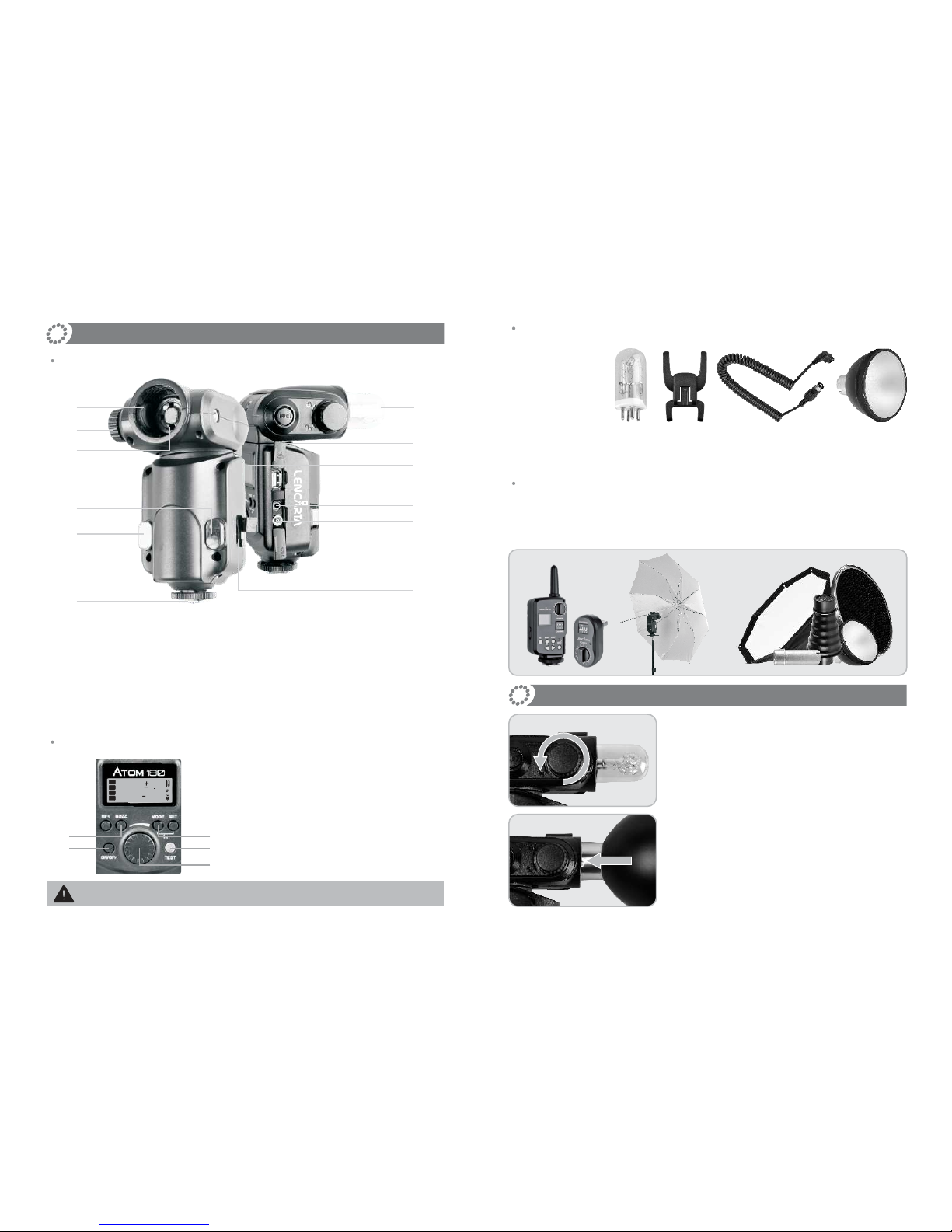
1. Flash tube*1
2. Protecting bag*1
3. Mini stand*1
4. Reflector*1
5. Power cable*1
6.
Reflector diffuserr*1
Name of Parts
01.
Reflector/Accessory Mount
08. Sync Cord Jack
02. Accessory Locking Ring09. PC Sync Socket
03. Flash Tube10. MF-Assist Beam
04. Tube Socket11.
Slave Sensor
05. Release Button12. Control Panel
06. Power Socket13. Hotshoe Stand
07. Wireless Control Port
14. LCD display
15. MF-Assist Beam Button
16.
Beep Button
17. MODE Selection Button
18. SET Button
19. ON/OFF Power Switch
20. Test Button/ Flash Ready Indicator
21. Select Dial
Body
Control Panel
The flash unit t draws its power from Lencarta AtomPower portable
battery pack (sold separately).
Included Accessories
Accessories available separately
The product can be used in combination with the following accessories:
Remote Control/radio trigger, dedicated Umbrella, Light Stand, Beauty Dish,
Snoot, Softbox, etc.
Fitting the Reflector
1. Rotate Accessory Locking Ring (2) counter-
clockwise until it is loose.
2. Insert the reflector into the Accessory Mount (1).
1
3
5
4
6
M
S
S
RPT
1
2
1
/
188 08
88
Times
88
Hz
21
20
17
18
14
19
16
15
- 03 -- 04 -
01
02
04
12
11
10
13
03
05
07
08
09
06
Page 5
- 05 -- 06 -
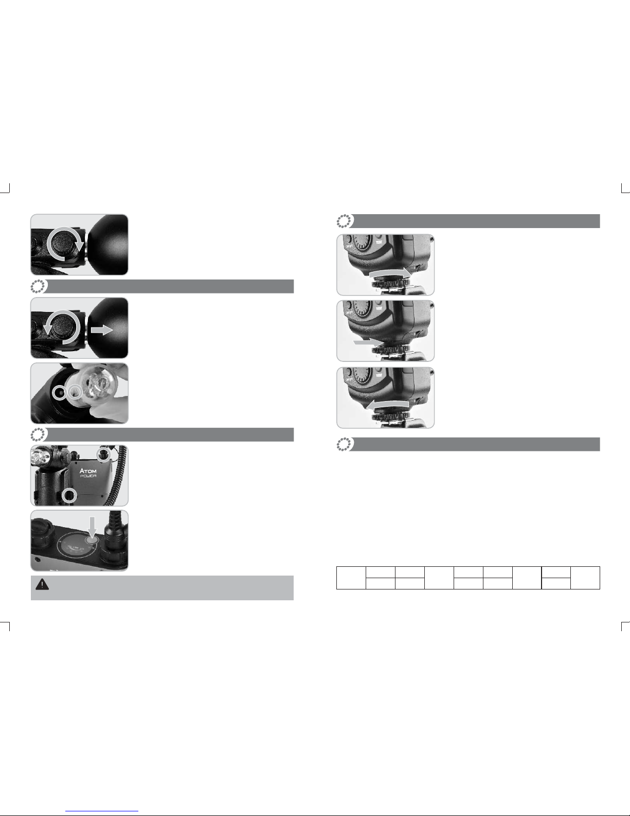
3. Rotate Accessory Locking Ring (2) clockwise to
lock it up. Do not over-tighten.
Attaching Flash Tube
1. Remove the reflector or other accessories from
the flash head.
2. Match the red dot on the base of the flash tube
with the red dot in the Tube Socket (4). Push the
flash tube in until it is securely seated into the
socket.
Connecting to an AtomPower Power Pack
1. Before connecting, make sure that the power
pack is turned off.
2. Plug one end of Power Cable into Power Socket
(6) of the flash unit, and insert the other end into
the output socket of the power pack.
3.
Turn on the power pack. The flash unit
will normally be fully charged and ready for use.
The flash unit is not powered by itself, but draws power from the Lencarta Atom
PowerPack (sold separately).
Connecting the Flash to a Camera
1. Loosen the screw on the mounting foot.
2. Slip the mounting foot of the flash unit into the
camera hotshoe.
3.
Secure the flash unit by locking up the screw, do
not overtighten it.
Using the Flash
1. Power Management
ON/OFF Power Switch (19) controls the on-and-off of the flash unit. Turn off the
power pack if the flash unit will not be used for an extended period.
1/1
1/1-0.31/1-0.7
1/2
1/2-0.31/2-0.7
1/4
…
OF
1/2+0.71/2+0.31/4+0.71/4+0.3
…
2. Flash Output
Flash output can be varied from 1/128th power to 1/1 full power in 1/3 stop
increments. To obtain a correct flash exposure, use a hand-held flash meter
to determine the required flash output, or refer to your camera histogram.
Adjust the power output by rotating Select Dial (21). The following table makes it
easier to see how the output changes in terms of f/stop when you increase or
decrease the flash output:
Figures displayed when reducing flash output level→
←Figures displayed when increasing flash output level
Page 6
- 07 -- 08 -
“OF” denotes OFF. When “OF” is shown on the LCD display, it means that there is
no flash output and flash firing is turned off.
3. M Mode: Manual Mode
Press MODE Selection Button (17) to enter M mode. In this mode, you can set the
flash unit onto either your camera hot shoe or your trigger hot shoe for firing.
Before shooting, adjust the power output of the ATOM 180. When the camera’s
shutter is pressed, the flash will fire. Slave triggering mode is not available in M
mode.
4. S1 Mode: S1 Slave Triggering Mode
Press Mode Selection Button (17) to enter S1 mode. In this mode, the flash unit can
function as a slave flash for creating multiple lighting effects.
In S1 mode, the flash unit will fire synchronously when the master flash fires, the
same effect as when fitted with a radio receiver.
5. S2 Mode: S2 Slave Triggering Mode
Press Mode Selection Button (17) to enter S2 mode. In this mode, the flash unit can
function as a slave flash for creating multiple lighting effects.
In S2 mode, the flash unit will ignore a single “preflash”from the master flash and will
only fire in response to the second, actual flash from the master.
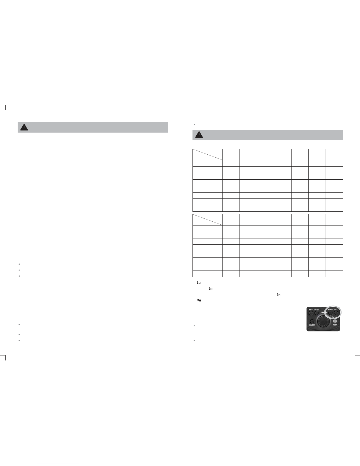
6. RPT Mode: Stroboscopic Flash
Press Mode Selection Button (17) to enter RPT mode (Multi/Stroboscopic flash).
With stroboscopic flash, a rapid series of flashes is fired. It can be used to capture
multiple images of a moving subject in a single photograph.
You can set the firing frequency (number of flashes per sec. expressed as Hz), the
number of flashes, and the flash output.
This is how it's done:
Press the Mode Selection Button (17) so that “RPT” is displayed.
Press Set Button (18) to select the item to be set. The item blinks when selected.
Rotate Select Dial (21) to set a desired number.
Calculating the Shutter Speed
During stroboscopic flash, the shutter remains open until the firing stops. Use the
following formula to calculate the shutter speed required to capture the full sequence
of flashes:
Number of flashes / Firing frequency = Shutter speed
For example, if the number of flashes is 10 and the firing frequency is 5 Hz, the
shutter speed should be at least 2 sec.
Note:
Stroboscopic flash is most effective with a light subject against a dark
background.
Using a tripod, a remote switch, and an external power source is recommended.
A flash output of 1/1 or 1/2 cannot be set for stroboscopic flash.
Stroboscopic flash can be used with “bulb”.
To avoid overheating and deteriorating the flash head, do not use stroboscopic flash
more than 10 times in succession.
Maximum Stroboscopic Flashes:
1/1
1/2
1/4
1/8
1/16
1/32
1/64
1/128
1
1
30
50
70
80
99
99
1
1
2
4
70
80
99
99
1
1
2
2
7
80
99
99
1
1
2
2
4
16
99
99
1
1
2
2
3
8
99
99
1
1
2
2
3
6
99
99
1
1
1
2
3
5
25
99
Flash Output
Hz
12
3
4
5
6
7
1/1
1/2
1/4
1/8
1/16
1/32
1/64
1/128
1
1
1
2
2
5
15
99
1
1
1
2
2
4
10
99
1
1
1
2
2
4
6
99
1
1
1
2
2
3
6
99
1
1
1
2
2
3
5
99
1
1
1
2
2
3
5
36
1
1
1
2
2
3
5
20
Flash Output
Hz
910-11
12-1313-15
15-1920-998
7. Hi-Speed Sync Triggering
To enter mode, press both Mode Selection Button (19) and Set Button (20).
Press Mode Selection Button (17) again to exit mode.
In hi-speed sync triggering mode, you can use a suitable hi-speed sync
trigger to have your flash unit synchronize with all shutter speeds available on
your camera.
This is convenient when you want to use aperture- priority for
fill-flash portraits.
Note:
Hi-speed sync triggering mode is effective only when the
flash unit is used together with a hi-speed sync trigger
Hi-speed sync triggering mode is not available when the flash unit is mounted
Page 7
- 09 -- 10 -
To avoid overheating or damaging the flash head, the over-temperature protection
function will be activated automatically after 10 continuous high-speed flashes in HSS
mode and the recycle time becomes 10s longer.
8. MF-Assist Beam
Under poorly-lit or low-contrast conditions, you can turn on the MF-assist beam
(15) in order to make it easier to autofocus. When the MF-assist beam is lit, is
shown on the LCD display.
9. Buzz Function
The beep function can be controlled by pressing BUZZ Button (16).
When the beep is turned on, is shown on the LCD display. The buzzer provides
an indication that the AD180 flash unit has fully recycled.
10. Wireless Control Function
The flash unit is built in with a Wireless Control Port (7) so that you can
wirelessly control the on-and-off of your flash, modelling lamp and beep, as well as
adjust the flash output level, etc.
To control the flash wirelessly, you need a you need a LENCARTA remote
control remote control set (on-camera and on-flash). Insert its receiver into the
Wireless Control Port (7) on the flash and insert the transmitter into the camera hot
shoe. Settings made on the hotshoe-mounted transceiver will be wirelessly
communicated to the flash. Then you can press the camera shutter-release button
to trigger the flash.
For full instructions on the use of LENCARTA remote control and flash trigger,
see its user manual.
When the flash unit receives wireless signals, is shown on the LCD display.
11.
Non-dedicated radio triggers
The Sync Cord Jack (8) is a standard Φ3.5mm plug. If required, a third party
radio receiver can be plugged into it to trigger the flash only,
12.
PC Sync cord Triggering
Insert one end of a PC sync cable into the PC Sync Socket (9) of the flash unit.
Overheat Protection Function
Over-Temperature Protection
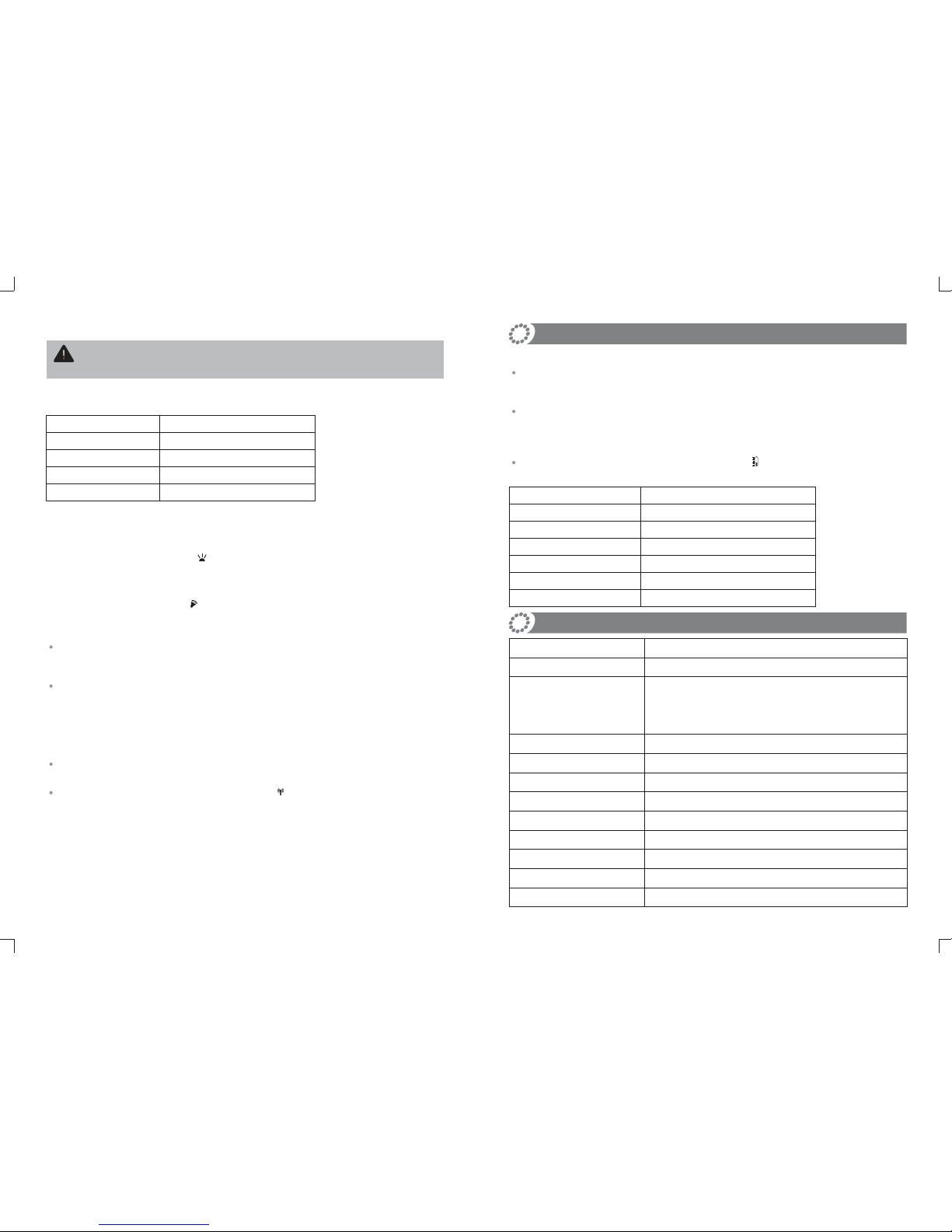
To avoid overheating and damaging the flash head, do not fire more than 75
continuous flashes in fast succession at full power. After 75 continuous flashes,
allow a rest time of at least 10 minutes.
After firing 75 continuous flashes at full power, the internal over-temperature
protection function may be activated and increase the recycling time to about 10 to
15 seconds. If this occurs, allow a rest time of about 10 minutes, and the flash unit
will then return to normal.
When the over-temperature protection is activated, this is shown on the LCD display.
Number of flashes that will activate over-temperature protection:
Power Output Level
1/1
1/2
1/4
1/8
1/16, 1/32
1/64, 1/128
Number of Flashes (Approx.)
75
100
200
300
400
500
Technical Data
Model
Max. Power
Guide No. (m ISO 100)
Vertical Rotation Angle
Horizontal Rotation Angle
Power Supply
Number of Flashes
Recycle Time
Colour Temperature
Flash Duration
Dimensions
Net Weight
ATOM 180
60 (m ISO 100, with standard reflector)
Approx. 28mm flash coverage when operating on a
camera with the standard reflector
-15°- 90°
0-270°
Power pack (ATOM POWER)
900 (With ATOM POWER power pack, at full power)
Approx. 0.05-2.6s (With ATOM POWER power pack)
5600±200k
1/800s - 1/10000s
205*90*70 mm (flash tube & reflector not included)
550g (flash tube & reflector not included)
180W/S
onto the camera hotshoe.
Power Output Level
1/1
1/2
1/4
1/8
Number of Flashes (Approx.)
10
15
20
30
Number of flashes that will activate over-temperature protection in high-speed sync
triggering mode:
Page 8

- 11 -
Maintenance
Shut down the device immediately should abnormal operation be detected.
Avoid sudden impacts.
It is normal for the flash tube to be warm when in use. Avoid continuous flashes
if possible.
Maintenance of the flash must be performed by our authorised maintenance
department which can provide original accessories. The flash-tube is user-
replaceable. Replacement tubes can be obtained from the manufacturer.
This product, except consumables e.g. flash tube, is supported with a 3 year
warranty.
Unauthorised service will void the warranty.
If the product has failed or become wet, do not use it until ithas been
inspected or repaired by our repair department.
Disconnect the power when cleaning the unit or when changing the flashtube.
Changes made to the specifications or designs may not be shown in this
manual.
 Loading...