


1
L-300 & L-400
OWNER'S MANUAL
IMPORTANT:
READ THIS MANUAL THOROUGHLY BEFORE OPERATING.
Sales and Service Centers across Canada.
VICTORIA • VANCOUVER • KELOWNA • CALGARY • EDMONTON • WINNIPEG • TORONTO • MONTRÉAL

2
INTRODUCTION
We appreciate your decision to purchase a LEMMER product. With proper maintenance (as
outlined in this manual) you will be assured years of excellent results. For prompt and courteous
service or advice, please contact any of our factory outlets which are listed on page 15.
SPRAY GUN OPERATION
LEMMER Electric Airless Spray Guns operate with a high pressure piston action pump, which
creates the pressure needed to finely atomize all sprayable materials. The piston movement is
obtained through the use of a 120 V, 60c/s oscillating motor. The resulting 120 piston strokes per
second are combined with a durable one-way valve to draw in paint, pressurize the paint, and
spray it out in a finely atomized mist. Since the mist is airless (no air used to convey the paint),
very little overspray is produced. The results are smooth finishes, minimal paint loss, and very easy
clean-up. Since many of today's paints have abrasive qualities, the LEMMER guns have been
specially designed to handle these tough paints. Extensive use of ceramics, and a specially
grooved tungsten carbide piston, make these airless spray guns extremely durable. Ceramics have
the advantage of being harder than tungsten carbide, as well as having very low friction values,
resulting in much less wear when compared to conventional materials.
Piston Control knob
Pump Cylinder
Spring
Valve
Nozzle
Suction Tube
TECHNICAL DATA
L-300 L-400
Power .....................................120 VAC/60HZ .............................. 120 VAC/60HZ...........................
Watts ...................................... 80 W .............................................. 90 W ..........................................
Amps ......................................2.0 A .............................................. 2.0 A ..........................................
Weight .................................... 3.3 lbs.(1.5 kg)............................... 3.5 lbs.(1.6 kg) ...........................
Maximum Volume ..................15 min./gal. .................................... 13 min./gal. ................................
Maximum Viscosity ................100 sec. ......................................... 110 sec. .....................................
Cylinder Material .................... Ceramic ......................................... Ceramic .....................................
Piston Material .......................Grooved tungsten carbide ............. Grooved tungsten carbide .........
Valve Cone ............................Self-centering ceramic ................... Self-centering ceramic ...............
Container ...............................37 oz (1.1Ltr) ................................. 37 oz (1.1Ltr) .............................

3
SAFETY PRECAUTIONS
Personal
1. Injection hazard: Airless Painting Equipment can cause serious injury if the
spray penetrates the skin. Do not point the gun at anyone or any part of the
body. The tip guard provides some protection against accidental injection
injuries, but is mostly a warning device. Never put your hand, fingers or body
over the spray tip. Gloves and clothing do not necessarily offer any protection
either. Always have the tip guard in place while spraying. In case of
penetration seek medical aid immediately! Note to physician: Injection
into skin is a serious traumatic injury. It is important to treat the injury
surgically as soon as possible. Do not delay treatment to research
toxicity. Toxicity is a concern with some exotic coatings injected into
the bloodstream. Consultation with a plastic surgeon or reconstructive
hand surgeon may be advisable. Be prepared to tell the doctor what
fluid was injected.
2. Do not spray paints or other inflammable fluids indoors which have a flash point below 21 degree C/70
degree F.
3. Keep spray area well ventilated. Before spraying, turn off all pilot lights and open flames.
4. Always unplug the spray gun before examining or leaving unattended.
5. Wear a respirator which is approved for the product being sprayed.
6. Extension cords - Use only a 3-wire extension cord that has a 3-blade grounding plug, and a 3-slot
receptacle that will accept the plug on the product. Make sure your extension cord is in good condition.
When using an extension cord, be sure to use one heavy enough to carry the current your product will draw.
An undersized cord will cause a drop in line voltage resulting in loss of power and overheating. Note: The
smaller the guage number, the heavier the cord is.
Maximum lengths and minimum guages are: 50 feet (15.24M) 16 guage
100 feet (30.48M) 14 guage
Equipment
1. Keep spray gun clean at all times.
2. All parts which are intended to contact paint will not be harmed by strong thinners.
3. Do not submerge the spray gun in any liquids.
4. Do not tilt the spray gun upwards while spraying. For jobs such as ceilings, use the flexible extension.
Failing this, paint could leak from the back of the pump.
5. Do not let the spray gun run without material in it. Material flowing through the pump acts as a cooling
agent.
Grounding Instructions
1. This product should be grounded. In the event of an electrical short circuit, grounding reduces the risk of
electric shock by providing an escape wire for the electric current. This product is equipped with a cord
having a grounding wire with an appropriate grounding plug. The plug must be plugged into an outlet that is
properly installed and grounded in accordance with all local codes and ordinances. DANGER - Improper use
of the grounding plug can result in a risk of electric shock.
2. If repair or replacement of the cord or plug is necessary, do not connect the grounding wire to either flat blade
terminal. The wire with insulation having an outer surface that is green with or without yellow stripes is the
grounding wire.
3. Check with a qualified electrician or serviceman if the
grounding instructions are not completely understood, or if in doubt as to whether the product is
properly grounded. Do not modify the plug provided;
if it will not fit the outlet, have the proper outlet
installed by a qualified electrician.
4. This product is for use on a nominal 120 volt circuit,
and has a grounding plug that looks like the plug
illustrated in sketch A. A temporary adapter, which
looks like the adapter illustrated in sketches B and C,
may be used to connect this plug to a 2-pole
receptacle as shown in sketch B if a properly
grounded outlet is not available. The temporary
adapter should be used only until a properly
grounded outlet (sketch A) can be installed by a
qualified electrician. The green colored rigid ear, lug,
or the like extending from the adapter must be
connected to a permanent ground such as a properly
grounded outlet box cover. Whenever the adapter is
used, it must be held in place by the screw.
HIGH PRESSURE!
INJECTION HAZARD!
GROUNDING METHODS
Grounded Outlet Adapter
Cover of Grounded
Outlet Box
(A) (B)
Grounding Pin
(C)
Grounding Means

4
OPERATING INSTRUCTIONS
Paint Preparation
1. Thin paint according to paint can instructions. Be certain to use a thinner which is compatible
with paint used. If no thinning instructions are given, a general rule of thumb is 5 to 15%
thinners. (fine finishes up to 35%)
2. Stir paint completely and strain if impurities are seen. The suction tube screen will strain out any
remaining impurities.
3. Use the viscosity cup to measure paint as follows:
Choosing the Correct Nozzle
1. Nozzle size is very important for achieving perfect paint atomization and maintaining a smooth
operating spray gun.
2. First prepare the paint, and then measure the paint’s viscosity as follows:
a) Submerge the Lemmer Viscosity cup in the paint.
b) Lift the cup out of the paint and begin timing.
c) Stop timing when the steady paint stream is first broken.
d) The time recorded is the paint’s viscosity. Should this viscosity
exceed 100 seconds, thin further until 80 - 100 seconds is reached.
3. Now read the nozzle chart and choose the “general use” nozzle which lists the viscosity range
your material falls into. Choice of a round spray or flat spray nozzle is dependent on your
preference. The other round spray nozzles listed are used for more specific spray applications
where “fine tuning” is necessary. Note: The smaller the nozzle size; the smaller the spray
pattern is, the less the volume is, and the thinner the paint must be.
Example: A latex paint was thinned and its viscosity came to 90 seconds. The chart suggests
either an .8mm round spray nozzle or a BLACK flat spray nozzle for this application.
4. This nozzle chart has been made as accurately as possible. Not all paints will exactly comply
due to paint ingredient variations. However, it is an excellent starting point for learning the
basics of airless spray painting
Round Spray Nozzle Flat Spray Nozzle
NOZZLE CHART
ROUND SPRAY
NOZZLE
.4mm
.5mm
.6mm
.7mm
.8mm
1.0mm
PAINT TO BE SPRAYED
THIN PAINTS - lacquer, varnish,
urethane, stains, automotive paints,
industrial enamel & primer, oil paints,
dye, ink and other thin liquids.
general use nozzle for thin paints
THICK PAINTS - latex, oil paint, stains,
(and glue - round nozzle only).
general use nozzle for thick paints
FLAT SPRAY
NOZZLE
BLUE
BLUE
BLUE
BLACK
BLACK
BLACK
CORRECT
VISCOSITY
10 - 15 sec.
10 - 20 sec.
10 - 35 sec.
35 - 45 sec.
35 - 100 sec.
65 - 100 sec.

5
OPERATING INSTRUCTIONS
5. The following diagrams show actual spray pattern results of different round nozzle sizes.
Remember - the thinner the paint is, the smaller the nozzle should be. These spray patterns
are achieved by spraying in one spot for only a fraction of a second.
Poor spray pattern Normal spray pattern Perfect spray pattern
(try a larger nozzle or (sometimes a smaller nozzle (correct nozzle and
thin the paint more) will "tighten-up" the pattern) paint viscosity)
Operation
1. Consult your paint dealer for information on surface preparation and material to be used for
spraying.
2. Prepare your paint and choose correct nozzle.
3. Practice on scrap material before proceeding to spray.
4. Turn control knob counter-clockwise and press trigger to start. CAUTION - when spraying, high
pressure is developed at the nozzle - never put any part of the body near the nozzle.
5. Adjust the control knob so the gun has an even purr, this signifies the best pressure setting for
that particular nozzle and material. If improperly adjusted, the following will result:
Too far counterclockwise - stuttering;
Too far clockwise - even, loud sound and less paint.
6. Any areas which are not to be painted should be masked off or
shielded. This diagram illustrates the best way of spraying a flat
surface with a round spray nozzle. Make smooth passes from side to
side and then up and down.
7. Start and stop your spraying from outside the area to be sprayed and try to avoid any break in
spraying. Move your gun with a steady motion to avoid spots, runs, and irregular finishes.
Keep the gun a constant distance from work surface and make sure it is perpendicular, as
shown below.
8. To prevent paint sags and running, first apply a light-to-medium coat. When this is tacky, apply
another medium coat.
9. When painting outdoors, avoid spraying on windy days. Wind could deposit debris onto your
freshly painted surface, and can also carry paint mist to areas which you do not want to paint;
such as windows, lawn furniture, cars, etc. It is also a good idea when spraying fences to have
a cardboard shield behind to prevent spraying paint directly into the air.
10.Note: It may be necessary to clean the nozzle guard periodically. Be sure to unplug the spray
gun’s electrical cord before doing this.

6
ACCESSORY INSTRUCTIONS
Suction Hose
Installation
1. Remove the paint container and the suction tube.
2. Insert the suction and return fittings firmly.
3. Press the clamp onto the lower end of the hoses.
4. Attach the clamp to the container and adjust the suction hose so
the screen is at the bottom. (Read on before using paint.)
5. Make sure the paint is properly prepared so that the screen is not
sitting in settled solids.
6. The return hose does not have to be below paint level, it’s only
function is to return possible pump by-pass paint.
Priming
1. Prime with thinners which are compatible with your paint, and then
place hoses into the paint.
2. To prime, hold the spray gun beside the container and as low as
possible. Turn the control knob counterclockwise and press the
trigger to start.
3. Priming time is generally between 20 and 40 seconds.
4. When primed, spraying may begin. Do not tilt the gun back while
spraying. Important: when using the suction hose the duty cycle is: half an hour on, and
15 minutes off to cool.
Flexible Extension
Installation
1. Remove spray nozzle.
2. Leave the valve in the pump cylinder.
3. Tighten flexible extension onto the spray
gun using the tabs nearest the gun.
Tightening from the far end will damage
the extension.
4. Remove the protective cap at the front.
5. Leave the swirl head in the flexible
extension and screw the nozzle on.
Tighten the nozzle while holding the front
tabs.
6. To bend the extension, use 2 thumbs in
the center and pull the end of the extension around your thumbs. To prevent
kinking or breaking, do not bend the
extension without using your thumbs.
Note: The suction hose and flexible exten-
sion may be used separately or together, but
keep in mind that some paints may spray
better with only one attachment in use at a
time.
Large
hose
goes
forward.
Make a large
bend to prevent
kinking.

7
MAINTENANCE
Cleaning
1. Only use thinners which are compatible with the paint to clean the gun.
2. Empty excess paint from the gun container and pour in one cup of thinners. Shake the gun
back and forth to flush the container, then spray for 5 seconds to flush pump parts. Properly
discard used thinners. Repeat if necessary.
3. Disassemble pump and clean all parts individually. Be sure the vent hole is clean and free.
CAUTION:
The piston is made of tungsten carbide which is long wearing, but also brittle -
Do
Not drop it or force it in any way.
Disassembly Procedure
STEP 1
1. Disconnect Power Supply.
2. Remove Nozzle.
3. Remove Valve.
4. Remove Container.
5. Remove Suction Tube.
6. Remove locking screw.
STEP 2
1. Push Pump Housing in.
2. Push Pump Housing down (1/4") slightly.
CAUTION - Do not force in any manner, if stuck, clean
first or try penetrating oil.
3. Pull Pump Housing straight out.
STEP 3
1. Pull Piston out. If it is stuck, do not pry or
hammer. See “Freeing a seized piston” on
page 8.
2. Remove Piston Spring. If piston spring
remained on piston, remove it by butting the
steel end of piston on a soft object and then
push the spring off with your fingers.
Pump Cylinder
Spring
Nozzle
Vent Hole
Piston
Valve
Suction tube
Strainer

8
MAINTENANCE
Cleaning
4. Reassemble in reverse order. Turning the control knob counterclockwise will reduce spring
tension for easy pump installation. Note that the guide tabs at the back of the pump must line
up with the gun housing. Firmly tighten the pump locking screw to insure it does not loosen
during operation. Check for correct pump positioning as shown.
Correct Incorrect
5. Dip suction tube into varsol or oil and spray for two seconds.
Then hold the gun with the suction tube out of the varsol (or
oil) and spray until empty. Another method is to remove the
suction tube, turn the gun upside down and pour a little oil
(or penetrating oil) into the forward pump hole. Hold your
finger lightly over the
suction hole
and spray until empty.
This will ensure that the spray gun is properly lubricated for
it’s next use.
Warning: NEVER put your fingers over the
spray nozzle.
6. Using a brush or rag dipped in thinners, clean the outside of
the spray gun. Do not submerge the spray gun in any liquids.
7. Wiping the gun with an oily rag will restore the gun’s new look and make it easier to clean the
next time.
8. Remember - A clean gun will always reward you with trouble free spraying.
Freeing a Seized Piston
This condition is usually caused by incomplete cleaning. Use the following procedure to rectify:
a) Remove nozzle, paint container, suction tube, and locking screw. If the valve is not
stuck, remove it too.
b) Remove pump assembly from gun and clean off all fresh paint with compatible thinners.
c) Place pump assembly into container of lacquer thinner for 1/2 an hour (longer if neces-
sary).
Caution
- read the warnings on lacquer thinner label before using.
d) GENTLY pull piston out of pump cylinder. If the valve was stuck, gently pull it out or use
the piston to push it out. Thoroughly clean all parts. The inside of the pump cylinder is
best cleaned with a 3/8” brush as shown on page 10.
e) Reassemble the spray gun.
suction hole
Loosen locking screw and push
pump in and up to position properly.
Pump sits level and
shows no gaps.
Gap.

9
MAINTENANCE
Parts That Wear
The round spray nozzle and the valve are common wear parts. Their life span depends on how
abrasive the paint is. A basic life expectancy with the use of various paints is:
Lacquer, enamel and clear stain 15 - 30 gallons
Alkyde, and oil stain 10 - 20 gallons
Latex and water base stain 5 - 10 gallons
These parts are easily replaceable and should be replaced when worn to maintain excellent
performance. Visual inspection for wear is as follows: (Operating sprayer with worn parts will
cause abnormal drive line wear).
1. Round spray nozzle - hole size of a new nozzle is shown actual size. Using a wire or
equivalent will help make a comparison between your nozzle and the dot.
New Nozzle Worn Nozzle
New nozzle
actual hole size:
.6mm =
.8mm =
Replace nozzle when hole
becomes larger than:
.6mm =
.8mm =
Round Orifice Large and usually oval orifice
2. Valve - A new valve will allow the gun to prime in approximately two seconds. If it takes eight
seconds or longer, replace the valve.
New Valve Worn Valve
Round and long Formed channels Angled and short Large “pit”
Servicing
If you have any problems with the electrical system, the spray gun should be returned to your
nearest Lemmer Authorized Service Centre.

10
POWER CONVERTER
Just plug into your vehicles lighter
socket to operate any Lemmer cup gun.
A standard car battery will run a cup gun
for about 4 hours and still have lots of
engine starting power.
Cup gun power inverter.........................
................................. Order # L075-165
VALVE KIT
This is a wearing part and having
spares will prevent possible down time.
Each kit contains 2 valves.
................................. Order # L075-103
CONTAINER WITH LID
For storing liquids and paint, or assisting
in quick color changes and thinning.
................................. Order # L075-111
SUCTION HOSE
For spraying out of the original paint
container. It makes the gun lighter and
more maneuverable. Approximately 6
feet long. .................. Order # L075-105
LINE-PRO
For painting 1" to 8" parking lot lines.
The resulting lines are the same as
those produced with large professional
units.
Line-Pro without spray gun (for the
L-400 only) ............... Order # L075-140
FLEXIBLE NOZZLE EXTENSION
To angle or extend the nozzle. For
spraying ceilings, floors, or hard to
reach areas (spray nozzle not included,
use any LEMMER optional nozzle, or
the one on the spray gun).
................................. Order # L075-104
ROUND SPRAY NOZZLES
For general purpose spraying. They
produce a finely atomized conical mist.
The .6mm and .8mm are general sizes
for thin and thick materials respectively.
.4mm for thin materials such as dye &
fluids......................... Order # L075-500
.5mm for fine enamel, etc. ....................
................................. Order # L075-501
.6mm for lacq., enamel, stain, some
latex, etc................... Order # L075-502
.7mm for latex, oil base, etc..................
................................. Order # L075-503
.8mm for latex, oil base, thick stains,
etc. ........................... Order # L075-504
1.0mm for thicker materials. .................
................................. Order # L075-505
FLAT SPRAY NOZZLES
For accurate spraying with less
overspray. Long wearing ceramic orifice
is designed for superior atomization.
Blue nozzle for lacquer, enamel, stain,
etc. ........................... Order # L075-112
Black nozzle for latex, oil base, thick
stains, etc. ................ Order # L075-113
REPAIR KIT
Complete pump assembly. Kit includes
pump cylinder, piston, piston spring, and
2 valves.
Repair kit .................. Order # L075-142
CLEANING BRUSHES
To assist in cleaning the spray gun
(these brushes are not affected by
strong paint thinners).
3/8" dia. for pump cylinder ....................
................................. Order # L075-109
5/8" dia. for general cleaning ................
................................. Order # L075-110
VISCOSITY CUP
An essential item for correct thinning of
paint and for proper nozzle selection.
................................. Order # L075-106
TIP BROACHES
For cleaning out plugged nozzles and
high pressure jets. Unique square
design quickly "reams" out foreign
obstructions.
(Package of 12) ....... Order # L033-021
ACCESSORIES

11
ELECTRIC CUP GUNS PNEUMATIC PISTON ELECTRIC DIAPHRAGM
LINEMARKERS
GAS DIAPHRAGM AIRLESS ACCESSORIES PAINTING SUNDRIES
AIR GUNS & PRESSURE POTS ELECTROSTATIC UNITS HVLP TURBINE & VENTURI UNITS
LEMMER'S full line of equipment comes with FIRST CLASS SERVICE in
numerous locations across CANADA, and a FULL ONE YEAR WARRANTY.
For information on choosing the right sprayer for your job, please
contact your nearest LEMMER outlet.
OTHER LEMMER EQUIPMENT
AUTOMATIC GUNS ELECTRIC PISTON PUMPS

12
PROBLEM:
Motor does not work
Motor hums quietly and
does not pump
Motor works but does not
pump
Sprays but spits occasionally
Poor spray pattern, or
sprays with irregular
clattering noise
Poor spray pattern with
flexible extension
Paint drips from nozzle
Excessive fogging
SOLUTION:
- Check plug connections and
power source
- Dismantle pump and clean
- Use only 120V A.C. Current
- Use only government
approved ext. cords
- Turn counterclockwise to
start
- Insert suction tube in front
hole
- Replace
- Thin accordingly
- Clean
- Replace
- Clean
- Clean (strain paint)
- Fill container
- Replace, see nozzle chart
- Replace
- Thin accordingly
- Adjust to an even hum. This
signifies perfect pressure
- Replace
- Replace
- Replace
- Hand tighten
- Hold sprayer closer
- Replace. See “Nozzle chart”
page 4
- Re-adjust control knob
CAUSE:
- Loose connection at plug or
no power in socket
- Seized piston
- Incorrect power supply
- Incorrect control knob
adjustment
- Sucking air
- Worn or missing valve
- Paint far too thick
- Plugged Nozzle, Valve or
Suction Screen
- Worn pump and/or piston
- Vent hole plugged
- Clogged suction filter
- Sucking air
- Incorrect or worn nozzle
- Worn valve
- Paint is wrong viscosity
- Incorrect control knob
adjustment
- Worn pump and/or piston
- Worn or missing swirl head
- Worn valve
- Loose nozzle
- Holding sprayer too far from
surface
- Incorrect or worn nozzle
- Control knob set too high
TROUBLE SHOOTING GUIDE
NOTE: Always unplug before examining. For further information contact a LEMMER Service Center.
13
1
3
4
5
6
33
34
32
35
7
8
9
11
11
10
31
2
6
13
12
14
15
16
17
18
19
20
21
22
23
21
24
25
26
27
25
30
28
24
24
29
36
37
34
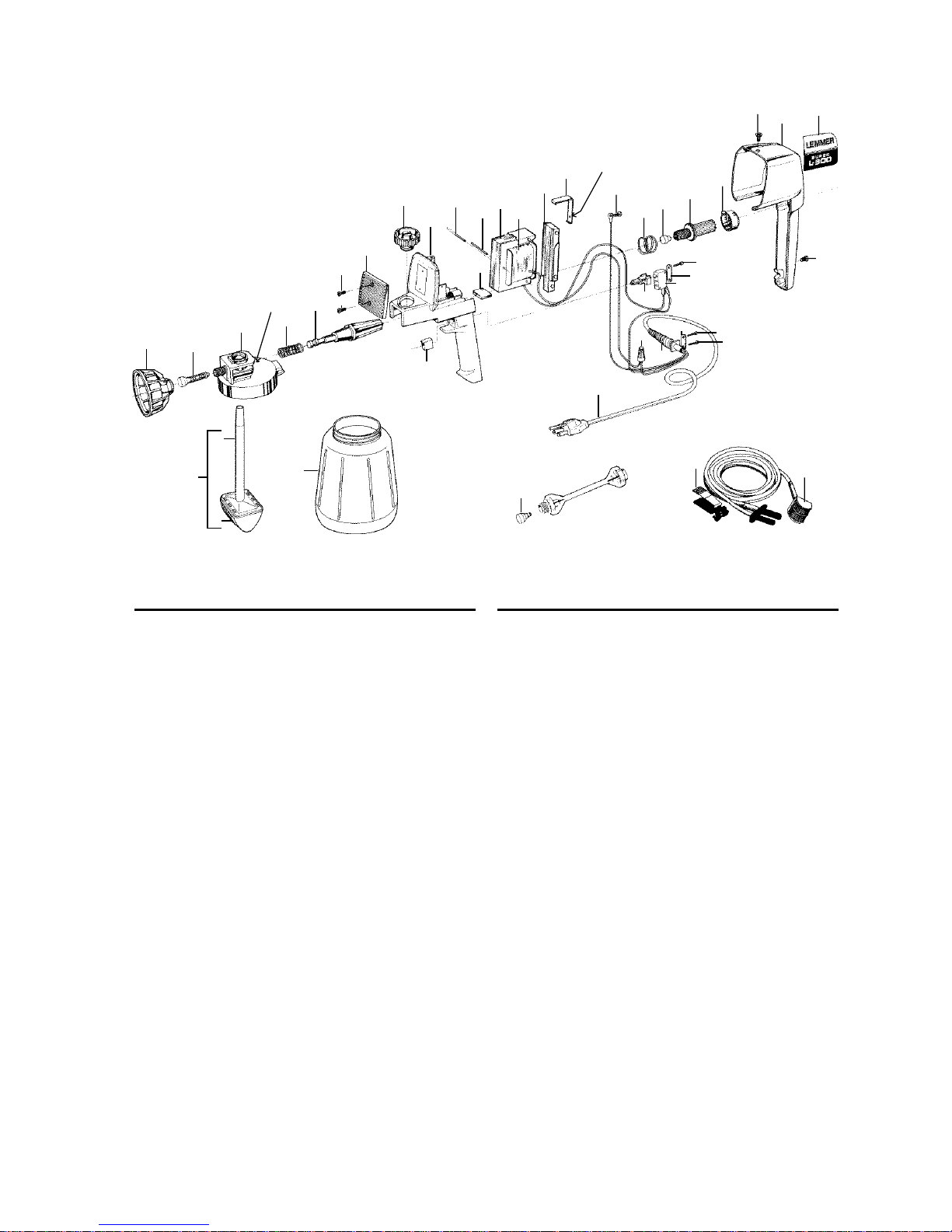
Pos. Part nos. Description Qty.
1 L075-500 .4mm Round spray nozzle
L075-501 .5mm Round spray nozzle
L075-502 .6mm Round spray nozzle
L075-503 .7mm Round spray nozzle
L075-504 .8mm Round spray nozzle 1
L075-505 1.0mm Round spray nozzle
2 L075-506 Valve 1
3 L075-700 Pump cylinder 1
4 L075-508 Piston spring 1
5 L075-701 Piston 1
6 L075-702 Screw 2
7 L075-703 Grill 1
8 L075-513 Locking screw 1
9 L075-704 Drive housing 1
10 L075-517 Damper 1
11 L075-512 Split pin 2
12 L075-705 Stator 1
13 L075-706 Coil 1
14 L075-707 Armature 1
15 L075-522 V-Spring 1
16 L075-708 Screw 1
Pos. Part nos. Description Qty.
17 L075-611 Spring 1
18 L075-523 Rubber bumper 1
19 L075-709 Control knob 1
20 L075-710 Limitor clip 1
21 L075-527 Screw 2
22 L075-711 Housing cover 1
23 L075-712 Name plate set 1
24 L075-713 Screw 4
25 L075-536 Cable clamp 2
26 L075-714 Switch 1
27 L075-715 Switch shaft 1
28 L075-530 Cable grommet 1
29 L075-531 Cable c/w grommet 1
30 L075-534 Wire connector 1
31 L075-716 Switch button 1
32 L075-540 Suction tube with filter 1
33 L075-538 Suction tube 1
34 L075-539 Suction filter 1
35 L075-537 Paint container 1
36 L075-124 Swirl head 1
37 L075-127 Clamp 1
N/S L075-142 Repair kit (pos.3,4,5,2) 1
N/S L075-262 Operators manual 1
Optional accessories.
This vent hole
must be kept
open.
Hole aims towards
back of gun.
L-300 PARTS LIST

14
33
34
32
35
20
1
3
4
2
5
6
7
9
8
9
10
11
12
13
31
14
15
16
16
17
18
19
24
25
26
27
30
25
24
24
29
28
21
21
22
23
34
37
36
L-400 PARTS LIST
Optional accessories.
This vent hole
must be kept
open.
Hole aims towards
back of gun.
Pos. Part nos. Description Qty. Pos. Part nos. Description Qty.
1 L075-500 .4mm Round spray nozzle
L075-501 .5mm Round spray nozzle
L075-502 .6mm Round spray nozzle
L075-503 .7mm Round spray nozzle
L075-504 .8mm Round spray nozzle 1
L075-505 1.0mm Round spray nozzle
2 L075-506 Valve 1
3 L075-700 Pump cylinder 1
4 L075-508 Piston spring 1
5 L075-701 Piston 1
6 L075-513 Locking screw 1
7 L075-719 Drive housing 1
8 L075-605 Damper 1
9 L075-512 Split pin 2
10 L075-705 Stator 1
11 L075-720 Coil 1
12 L075-707 Armature 1
13 L075-522 V-Spring 1
14 L075-721 Handle 1
15 L075-708 Screw 1
16 L075-722 Screw 2
17 L075-611 Spring 1
18 L075-523 Rubber bumper 1
19 L075-709 Control knob 1
20 L075-710 Limitor clip 1
21 L075-527 Screw 2
22 L075-717 Housing cover 1
23 L075-723 Name plate set 1
24 L075-713 Screw 4
25 L075-536 Cable clamp 2
26 L075-714 Switch 1
27 L075-715 Switch shaft 1
28 L075-530 Cable grommet 1
29 L075-531 Cable c/w grommet 1
30 L075-534 Wire connector 1
31 L075-716 Switch button 1
32 L075-540 Suction tube with filter 1
33 L075-538 Suction tube 1
34 L075-539 Suction filter 1
35 L075-537 Paint container 1
36 L075-124 Swirl head 1
37 L075-127 Clamp 1
N/S L075-142 Repair kit (pos.3,4,5,2) 1
N/S L075-262 Operators manual 1

15
SALES AND SERVICE CENTERS ACROSS CANADA.
If you should require any information, assistance, service, or parts, please contact the store from
which the spray gun was purchased, or contact the Lemmer outlet nearest you.
Printed in Canada, #L075-262 manual for L-300/L-400. Aug-98
LEMMER PAINT SPRAYING EQUIPMENT LIMITED WARRANTY
LEMMER Spray Systems Ltd. extends to the original purchaser of its paint spray equipment
a limited one year warranty from the date of purchase against defects in material or
workmanship provided that the equipment is installed and operated in accordance with the
recommendations and instructions written in the owners manual. LEMMER Spray Systems Ltd.
will repair or replace, at its option, defective parts without charge if such parts are returned (still
intact in the original equipment) with transportation charges prepaid to the nearest LEMMER
Spray Systems Ltd. outlet. An original proof of purchase must be attached.
THIS WARRANTY DOES NOT COVER:
Normal wear and/or defects caused by or related to abrasion, corrosion, abuse, negligence,
accident, faulty installation or tampering in a manner which impairs normal operation.
Transportation costs and other incidental, direct, special, or consequential damages or loss.
MONTRÉAL
Lemmer (Qué.) Inc.
2851 Boul. le Corbusier
Chomedey, Laval, Québec H7L 4J5
TEL: (450) 681-8220
FAX: (450) 681-4914
TORONTO
Lemmer Spray Systems (Ont.) Ltd.
7585 Torbram Road, Unit 7-8
Mississauga, Ontario L4T 1H2
TEL: (905) 673-1555
FAX: (905) 673-3201
WINNIPEG
Lemmer Spray Systems (Man.) Ltd.
1198 Sherwin Road
Winnipeg, Manitoba R3H 0V2
TEL: (204) 633-3117
FAX: (204) 694-4763
VICTORIA
Lemmer Spray Systems (B.C.)Ltd.
#102 - 2740 Bridge Street
Victoria, B.C. V8T 5C5
TEL: (250) 383-4464
FAX: (250) 383-5154
VANCOUVER
Lemmer Spray Systems (B.C.) Ltd.
4141 Grandview Highway
Burnaby, B.C. V5C 4J1
TEL: (604) 430-3216
FAX: (604) 430-8017
KELOWNA
(Lemmer agent)
R. Kitchin Paint Spray Equipment Inc.
#3 - 2300 Hunter Road
Kelowna, B.C. V1X6C1
TEL: (250) 717-0223
FAX: (250) 860-3038
CALGARY
Lemmer Spray Systems Ltd.
4624 - 12th Street N.E.
Calgary, Alberta T2E 4R4
TEL: (403) 250-7735
FAX: (403) 291-9095
(head office)
EDMONTON
Lemmer Spray Systems Ltd.
17506 - 105th Avenue
Edmonton, Alberta T5S 1G4
TEL: (403) 486-3674
FAX: (403) 444-2498

16
NOTES
 Loading...