

Page 1

CODE: 277.328
AMP SERIESAMP SERIES
HEAVY DUTY POWER AMPLIFIERHEAVY DUTY POWER AMPLIFIER
Page 2
IMPORTANT SAFETY INSTRUCTIONS
INSTRUCTIONS PERTAINING TO A RISK OF FIRE, ELECTRIC SHOCK OR INJURY TO PERSONS
WARNING - When using electric products, basic precautions should always be followed,
including the following:
1. Read all the SAFETY INSTRUCTIONS before using the product.
2. This product must be earthed. If it should malfunction or break down, grounding provides a path of
least resistance for electric current to reduce risk of electric shock.
This product is equipped with a cord having an equipment-grounding conductor and a grounding plug.
The plug must be plugged into an appropriate outlet that is properly installed and earthed in accordance
with all local codes and ordinance.
DANGER
- Improper connection of the equipment-grounding connector can result in a risk of
electric shock. Check with a qualified electrician or serviceman if you are in doubt as to whether the
product is properly grounded. Do not modify the plug provided with the product - if it will not fit the outlet,
have a proper outlet installed by a qualified electrician.
3. To reduce the risk of injury, close supervision is necessary when the product is used near children.
4. Do not use this product near water - for example, near a bathtub, washbowl, kitchen sink, in a wet
basement or near a swimming poor or the like.
5. This product may be capable of producing sound levels that could cause permanent hearing loss.
Do not operate for a long period of time at high volume level or at a level that is uncomfortable. If you
experience any hearing loss or ringing in the ears, you should consult an audiologist.
6. This product should be located so that its location or position does not interfere with its proper
ventilation.
7. This product should be located away from heat sources such as radiators, heat registers or other
products that produce heat.
8. The product should be connected to a power supply only of the type described on the operating
instructions or as marked on the product.
9. This product may be equipped with a polarized line plug (one blade wider than the other). This is a
safety feature. If you are unable to insert the plug into the outlet, contact an electrician to replace your
obsolete outlet. Do not defeat the safety purpose of the plug.
10. The power-supply cord of the product should be unplugged from the outlet when left unused for a
long period of time. When unplugging the power-supply cord, do not pull on the cord, but grasp it by
the plug.
11. Care should be taken so that object do not fall and liquid are not spilled into the enclosure through
openings.
12. The product should be serviced by qualified service personnel when:
A. The power-supply cord or the plug has been damaged; or
B. Objects have fallen, or liquid has been spilled into the product; or
C. The product has been exposed to rain; or
D. The product does not appear to operate normally or exhibits a marked change in performance; or
E. The product has been dropped or the enclosure damaged.
13. Do not attempt to service the product beyond that described in the user-maintenance instructions.
All other servicing should be referred to qualified service personnel.
14.
WARNING - Do not place objects on the product's power cord or place it in a position where
anyone could trip over, walk on or roll anything over it. Do not allow the product to rest on or to be installed
over power cords of any type. Improper installations of this type create the possibility of fire hazard and/
or personal injury.
SAVE THESE INSTRUCTIONS
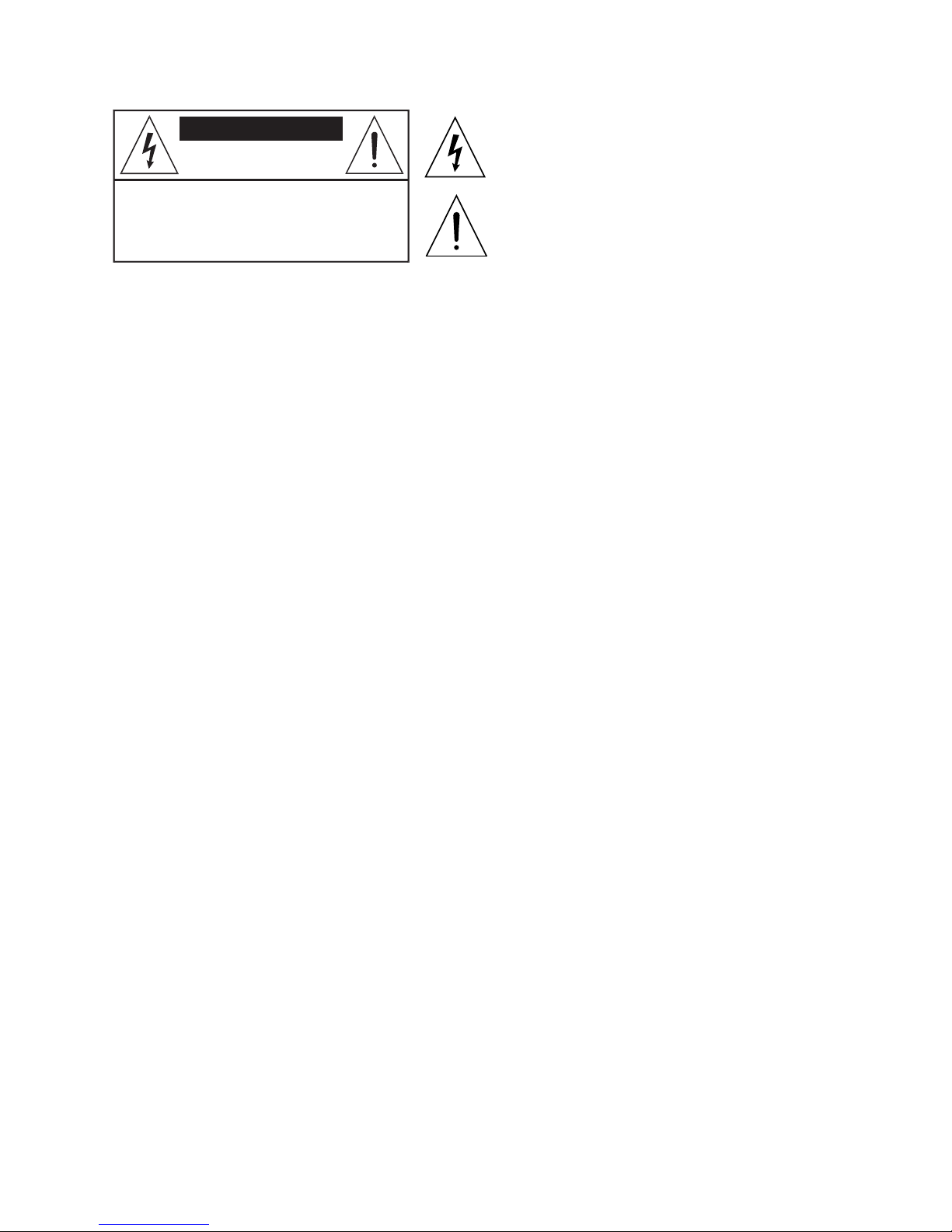
CAUTION
RISK OF ELETRIC SHOCK
DO NOT OPEN
CAUTION: TO REDUCE THE RISK OF ELETRIC
SHOCK DO NOT REMOVE COVER (OR BACK)
NO USER-SERVICEABLE PARTS INSIDE
REFER SERVICING TO QUALIFIED PERSONNEL
The lightning flash with arrowhead symbol within an
equilateral triangle is intended to alert the user to the
presence of uninsulated "dangerous voltage" within the
product's enclosure, that may be of sufficient
magnitude to constitute a risk of electric shock to
persons.
The exclamation point within an equilateral triangle is
intended to alert the user to the presence of important
operating and maintenance (servicing) instructions in
the literature accompanying the appliance.
Page 3

1
AMP SERIE
S
Indice
Presentazione . . . . . . . . . . . . . . . . . . . . . . . . . . . . . . . . . . . . . . . 2
Norme di installazione ed uso . . . . . . . . . . . . . . . . . . . . . . . . . . 3
Funzioni & controlli . . . . . . . . . . . . . . . . . . . . . . . . . . . . . . . . . . 5
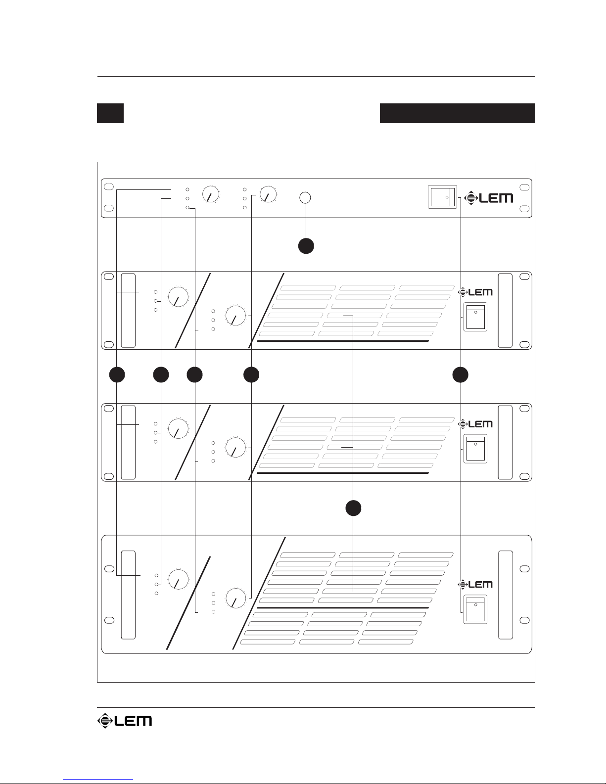
PROTECT LEDs . . . . . . . . . . . . . . . . . . . . . . . . . . . . . . . . . . . . . . . . . . . . . 7
LIMIT LEDs . . . . . . . . . . . . . . . . . . . . . . . . . . . . . . . . . . . . . . . . . . . . . . . . 7
SIGNAL LEDs . . . . . . . . . . . . . . . . . . . . . . . . . . . . . . . . . . . . . . . . . . . . . . 7
LEVEL . . . . . . . . . . . . . . . . . . . . . . . . . . . . . . . . . . . . . . . . . . . . . . . . . . . . 8
PHONES . . . . . . . . . . . . . . . . . . . . . . . . . . . . . . . . . . . . . . . . . . . . . . . . . . 8
PRESE d'ARIA . . . . . . . . . . . . . . . . . . . . . . . . . . . . . . . . . . . . . . . . . . . . . . 8
POWER ON. . . . . . . . . . . . . . . . . . . . . . . . . . . . . . . . . . . . . . . . . . . . . . . . 8
OUTPUTS . . . . . . . . . . . . . . . . . . . . . . . . . . . . . . . . . . . . . . . . . . . . . . . . . 8
GND . . . . . . . . . . . . . . . . . . . . . . . . . . . . . . . . . . . . . . . . . . . . . . . . . . . . . 9
GROUND ON / FLOATING . . . . . . . . . . . . . . . . . . . . . . . . . . . . . . . . . . . . 9
LIMITER ON/OFF . . . . . . . . . . . . . . . . . . . . . . . . . . . . . . . . . . . . . . . . . . . 9
Selettore PARALLEL/STEREO/BRIDGE . . . . . . . . . . . . . . . . . . . . . . . . . . . . 9
INPUTS . . . . . . . . . . . . . . . . . . . . . . . . . . . . . . . . . . . . . . . . . . . . . . . . . . 11
Cavi di collegamento . . . . . . . . . . . . . . . . . . . . . . . . . . . . . . . . 13
Specifiche tecniche . . . . . . . . . . . . . . . . . . . . . . . . . . . . . . . . . . 14
Indice
Page 4

2
AMP SERIE
S
Congratulazioni per l'acquisto di un amplificatore di potenza AMP SERIES!
Gli AMP SERIES sono amplificatori compatti di elevata potenza, progettati per soddisfare le
esigenze più diverse nel campo dellamplificazione sonora.
Gli amplificatori AMP SERIES sono stati realizzati con una concezione strutturale che si basa
sui seguenti presupposti:
a) aumento dei rendimenti con diminuzione delle potenze dissipate;
b) efficace sistema di protezioni, in grado di tenere costantemente sotto controllo i principali
parametri di funzionamento dellamplificatore, per garantire la massima affidabilità ed un
utilizzo in condizioni di sicurezza;
c) maggiore compattezza della struttura a favore di un migliore rapporto prezzo/prestazioni.
Questa particolare struttura ha reso possibile il raggiungimento di prestazioni decisamente
notevoli, quali potenza elevata in dimensioni e pesi contenuti, grande capacità dinamica,
ottima qualità timbrica ed assoluta affidabilità in qualunque condizione di utilizzo.
Gli amplificatori della serie AMP sono disponibili in quattro diversi modelli:
AMP 1
2
ê 600+600 Watts / 4W BRIDGE 1300 Watts / 8W
AMP
8
ê 400+400 Watts / 4W BRIDGE 850 Watts / 8W
AMP
4
ê 200+200 Watts / 4W BRIDGE 420 Watts / 8W
AMP 2.
4
ê 120+120 Watts / 8W
Le connessioni di qualità (connettori SPEAKON in uscita, tranne AMP 2.4), le manopole,
gli interruttori ed il robusto contenitore metallico fornito di maniglie sono realizzati per
consentire un uso intenso senza problemi.
Il comodo display a LEDs consente una chiara visione dello status degli amplificatori in
qualsiasi condizione di illuminazione.
Gli AMP SERIES sono adatti a tutti i tipi di utilizzo in cui si richiedano amplificatori potenti,
versatili ed affidabili, con dimensioni compatte ed un ottimo rapporto prezzo/prestazioni:
dai sistemi di amplificazione da trasporto alle installazioni fisse, dai sistemi di multiamplificazione ai setups casalinghi.
Presentazione
Presentazione
Page 5
3
AMP SERIE
S
Norme di installazione ed uso
Norme di installazione ed uso
PCollegamento alla rete.
Prima di collegare lamplificatore alla presa di corrente, accertatevi che la tensione di rete
corrisponda a quella indicata sul retro dellapparato (è accettata una tolleranza fino a
±10%).
Prima di collegare il cavo di alimentazione alla presa di rete, accertatevi sempre che questo
non sia danneggiato o addirittura con fili scoperti. Collegate il cavo di alimentazione alla
presa di rete sempre
prima di accendere lamplificatore e rimuovete il cavo sempre dopo averlo spento.
PAccensione e spegnimento.
Ricordate di effettuare o rimuovere i collegamenti con altri apparati sempre
ad amplificatore spento e di
accendere sempre
prima il mixer e poi lamplificatore: eviterete, così, picchi di segnale fastidiosi e talvolta
pericolosi specialmente per i diffusori. E normale che allaccensione, i LED di segnalazione rimangano
illuminati per alcuni istanti.
PIl trattamento.
Non forzate connettori e manopole: sono studiati per rispondere ad una leggera pressione e potrebbero
essere danneggiati se manipolati con forza eccessiva.
PCollegamenti e prevenzione di possibili disturbi.
Evitate di installare la vostra attrezzatura in stretta prossimità di apparecchi TV, radio, etc., in quanto
potrebbero causare interferenze rumorose. Collegando gli apparati del vostro impianto audio, ponete molta
attenzione ai cosiddetti loop di massa che potrebbero causare ronzii: in caso di disturbi, provate ad agire
sullo switch GROUND ON/FLOATING posto sul pannello controlli dellamplificatore.
PI cavi di collegamento.
Per il collegamento dellamplificatore al mixer accertatevi di utilizzare
sempre e solo cavi di segnale
(cavi schermati, costituiti da due fili più una calza che funge da schermo) e
non cavi di potenza (cavi
colonna costituiti solo da due fili, in genere di sezione maggiore): lutilizzo di cavi non schermati, infatti,
potrebbe facilmente determinare linsorgere di fastidiosi ronzii e rumori di fondo. Per il collegamento
dellamplificatore alle casse, invece, utilizzate
sempre e solo cavi di potenza e non cavi di segnale:
in questultimo caso, infatti, la potenza erogata dagli amplificatori andrebbe in parte dispersa a causa della
ridotta sezione del cavo. Abbiate cura dei cavi di collegamento, afferrandoli sempre per i connettori, evitando
di tirarli lungo il cordone ed avvolgendoli sempre evitando nodi e forti torsioni: ne allungherete la vita e
laffidabilità, a vostro assoluto vantaggio.
PLa circolazione dellaria per il raffreddamento.
Il giusto raffreddamento degli amplificatori è assicurato da una ventola interna, controllata in velocità da
un apposito sensore (la velocità è proporzionale alla potenza erogata e quindi alla temperatura generata):
ricordatevi di non ostruire in alcun modo le prese daria poste sui lati degli amplificatori (tranne AMP 2.4),
attraverso le quali avviene il passaggio dell'aria necessaria per il raffreddamento. Durante luso, se tenete
gli amplificatori in contenitori tipo flight-cases, accertatevi che essi presentino delle aperture sufficienti in
corrispondenza di entrambe le prese daria. Evitate collocazioni troppo anguste che non consentano una
corretta circolazione daria.
Page 6

4
AMP SERIE
S
PLa protezione e la manutenzione.
E buona norma, per non compromettere il corretto funzionamento delamplificatore, evitare di posizionarlo
per tempi troppo prolungati in luoghi esposti allazione di agenti atmosferici (umidità, temperature molto
elevate, ecc.), allaccumulo di polvere e a vibrazioni troppo intense.
In caso di avaria non aprite lamplificatore, ma rivolgetevi al più vicino Centro di Assistenza
GENERALMUSIC.
PLa conservazione della documentazione e dellimballaggio.
Conservate questo manuale duso per eventuali future consultazioni. Conservate, inoltre, tutti i materiali di
imballaggio per future spedizioni. Ricordate a questo proposito che sul mercato dellusato un prodotto ottiene
sempre una migliore valutazione se, oltre ad essere ben conservato, è corredato della documentazione e
dellimballaggio originali.
Norme di installazione ed uso
Page 7
5
AMP SERIE
S
Funzioni & controlli
Funzioni & controlli
POWER
AMP 4
16
16
-0
-0
0
0
18
18
32
32
56
56
40
40
22
22
26
26
0
0
12
12
2
2
10
10
6
6
4
4
8
8
14
14
PROTECT
PROTECT
LIMIT
LIMIT
SIGNAL
SIGNAL
CH 1
CH 2
HEAVY DUTY POWER AMPLIFIER
PROTECT
CLIP
SIGNAL
CHANNEL 1
PROTECT
CLIP
SIGNAL
CHANNEL 2
POWER
AMP 2.4
PHONES
16
-0
0
18
32
56
40
22
26
0
12
2
10
6
4
8
14
16
-0
0
18
32
56
40
22
26
0
12
2
10
6
4
8
14
HEAVY DUTY POWER AMPLIFIER
POWER
AMP 8
16
16
-0
-0
0
0
18
18
32
32
56
56
40
40
22
22
26
26
0
0
12
12
2
2
10
10
6
6
4
4
8
8
14
14
PROTECT
PROTECT
LIMIT
LIMIT
SIGNAL
SIGNAL
CH 1
CH 2
HEAVY DUTY POWER AMPLIFIER
POWER
AMP 12
HEAVY DUTY POWER AMPLIFIER
16
16
-0
-0
0
0
18
18
32
32
56
56
40
40
22
22
26
26
0
0
12
12
2
2
10
10
6
6
4
4
8
8
14
14
PROTECT
PROTECT
LIMIT
LIMIT
SIGNAL
SIGNAL
CH 1
CH 2
1
2
3
4
5
6
7
Page 8
6
AMP SERIE
S
Funzioni & controlli
100V50/60Hz
120V50/60Hz
230V50/60Hz
240V50/60Hz
AMPLIFIER OUTPUTS AMPLIFIER INPUTS
CH 2 CH 2
GROUND PARALLELFLOATING
STEREO
ON
CH 1
MIN.LOAD
8Ohm
CH 1
AC
~
AVIS:
RISQUEDE CHOC ELECTRIQUE-NE PAS OUVRIR
RISKOF ELECTRIC SHOCK
DONOT OPEN
CAUTION
"WARNING"
TOREDUCE THE RISK OF
FIREOR ELECTRIC SHOCK DONOT EXPOSE
THISPRODUCT TO RAIN OR MOISTURE.
AMP 2.4
HEAVYDUTY POWER AMPLIFIER
BY
GENERALMUSICs.p.a.
MADEIN CHINA
100V50/60Hz
120V50/60Hz
230V50/60Hz
240V50/60Hz
AMPLIFIER OUTPUTS
AMPLIFIER INPUTS
CH 2 CH 1
MIN4 Ohm MIN4 Ohm
CH 2
CH 2
GND
CH 1
GROUND PARALLELONFLOATING
BRIDGEOFF
STEREOLIMITER
ON
BRIDGED
+
++
_
__
8Ohm
CH 1
GND
AC
~
AVIS:
RISQUEDE CHOC ELECTRIQUE-NE PAS OUVRIR
RISKOF ELECTRIC SHOCK
DONOT OPEN
CAUTION
"WARNING"
TOREDUCE THE RISK OF
FIREOR ELECTRIC SHOCK DONOT EXPOSE
THISPRODUCT TO RAIN OR MOISTURE.
BY
GENERALMUSICs.p.a.
MADEIN CHINA
AMP 12
HEAVYDUTY POWER AMPLIFIER
100V50/60Hz
120V50/60Hz
230V50/60Hz
240V50/60Hz
AMPLIFIER OUTPUTS
CH 2 CH 1
MIN4 Ohm MIN4 Ohm
GND
GROUND PARALLELONFLOATING
BRIDGEOFF
STEREOLIMITER
ON
BRIDGED
+
_
8Ohm
AC
~
BY
GENERALMUSICs.p.a.
AVIS:
RISQUEDE CHOC ELECTRIQUE-NE PAS OUVRIR
RISKOF ELECTRIC SHOCK
DONOT OPEN
CAUTION
"WARNING"
TOREDUCE THE RISK OF
FIREOR ELECTRIC SHOCK DONOT EXPOSE
THISPRODUCT TO RAIN OR MOISTURE.
MADEIN CHINA
AMP 4
HEAVYDUTY POWER AMPLIFIER
AMPLIFIER INPUTS
CH 2
CH 2 CH 1
++
__
CH 1
GND
100V50/60Hz
120V50/60Hz
230V50/60Hz
240V50/60Hz
AMPLIFIER OUTPUTS
CH 2 CH 1
MIN4 Ohm MIN4 Ohm
GND
GROUND PARALLELONFLOATING
BRIDGEOFF
STEREOLIMITER
ON
BRIDGED
+
_
8Ohm
AC
~
BY
GENERALMUSICs.p.a.
AVIS:
RISQUEDE CHOC ELECTRIQUE-NE PAS OUVRIR
RISKOF ELECTRIC SHOCK
DONOT OPEN
CAUTION
"WARNING"
TOREDUCE THE RISK OF
FIREOR ELECTRIC SHOCK DONOT EXPOSE
THISPRODUCT TO RAIN OR MOISTURE.
MADEIN CHINA
AMP 8
HEAVYDUTY POWER AMPLIFIER
AMPLIFIER INPUTS
CH 2
CH 2 CH 1
++
__
CH 1
GND
8
9
10
6
Page 9

7
AMP SERIE
S
1
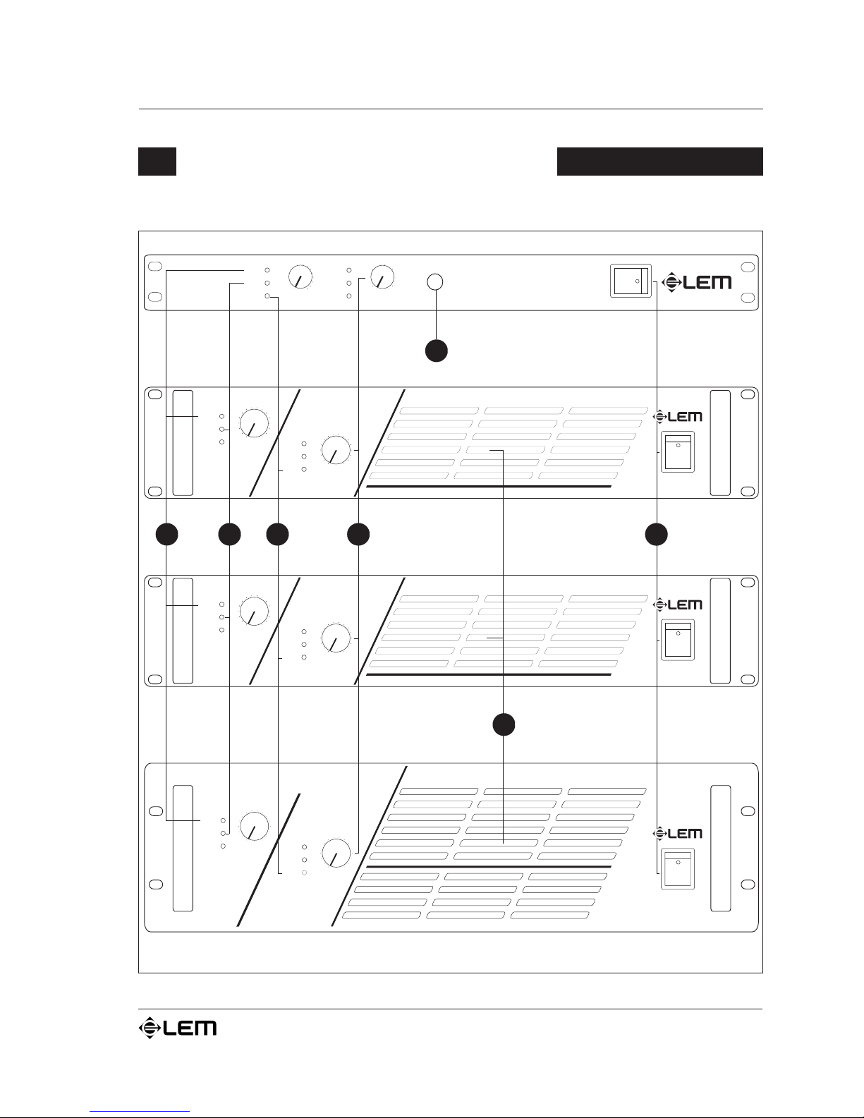
PROTECT LEDs
Indicatori di intervento delle protezioni.
Leventuale accensione di questi LEDs segnala lattivazione di una
delle protezioni che salvaguardano le diverse sezioni
dellamplificatore (ed eventualmente anche i diffusori) in caso
di condizione anomala di funzionamento. In questi casi,
lerogazione della potenza viene normalmente sospesa fino al
ripristino delle corrette condizioni di funzionamento.
Le protezioni installate sugli amplificatori della serie AMP sono
le seguenti:
1) PROTEZIONE SUI DIFFUSORI: in caso di malfunzionamento,
un rilevatore posto sulle uscite di potenza è in grado di
interrompere il circuito evitando che picchi di corrente
raggiungano i diffusori e li danneggino.
2) PROTEZIONE TERMICA SUL DISSIPATORE: questa
protezione interviene ogni volta che si verifica un innalzamento
eccessivo della temperatura a livello del dissipatore interno.
3) PROTEZIONE DAL CORTO CIRCUITO: questa protezione
agisce in caso di corto circuito o sovraccarico, limitando la
corrente in uscita.
Alcune situazioni di protezione possono richiedere che lamplificatore
venga spento e poi riacceso per il ripristino delle normali condizioni di
funzionamento.
2
LIMIT LEDs
Indicatori di status dellamplificatore: si tratta di LEDs in
grado di indicare, per i rispettivi canali A&B, lintervento del
limiter interno, quando inserito, o la saturazione
dellamplificatore.
Questi 2 LEDs sono POSTLEVEL: in altre parole visualizzano
lo status del segnale già regolato dai controlli di livello in
ingresso.
3
SIGNAL LEDs
Indicatori di status del segnale: si tratta di LEDs in grado
di indicare, per i rispettivi canali A&B, la presenza di un segnale
in ingresso allamplificatore.
Funzioni & controlli
Page 10

8
AMP SERIE
S
4
LEVEL
Controllo di livello dingresso del segnale esterno: agisce con
valori continui che vanno da
tutto chiuso (posizione ¥: il
segnale
non viene inviato alle sezioni dellamplificatore) a tutto
aperto (posizione 0dB: il segnale viene inviato alle sezioni
dellamplificatore con lo stesso livello con cui giunge in
ingresso). In altre parole, questo controllo agisce come un
attenuatore del segnale esterno verso lamplificatore.
5
PHONES
Uscita di cuffia stereo: il modello AMP 2.4 è provvisto di una
uscita alle quale è possibile collegare una cuffia STEREO con
impedenza minima di 200W. Collegando la cuffia a questa uscita
vengono automaticamente disattivate le uscite principali
dellamplificatore e, di conseguenza, i controlli di livello del
segnale di ingresso possono essere utilizzati come controlli di
volume per la cuffia stessa.
6
PRESE d'ARIA (AMP 4,8 & 12)
Prese d'aria del sistema di raffreddamento dell'amplificatore.
La ventola del sistema di raffreddamento degli amplificatori
AMP SERIES crea un flusso d'aria con scorrimento in direzione
davanti/dietro: ciò significa che l'aria viene prelevata
dall'apertura posta sul fronte e, dopo aver raffreddato i
dissipatori ed il trasformatore di rete, viene espulsa attraverso
l'apertura posta sul retro. Fate attenzione a non ostruire mai
queste aperture e ricordate di non tener mai l'amplificatore in
collocazioni che non consentano una sufficiente circolazione
dell'aria.
7
POWER ON
Interruttore di accensione/spegnimento con LED di
segnalazione.
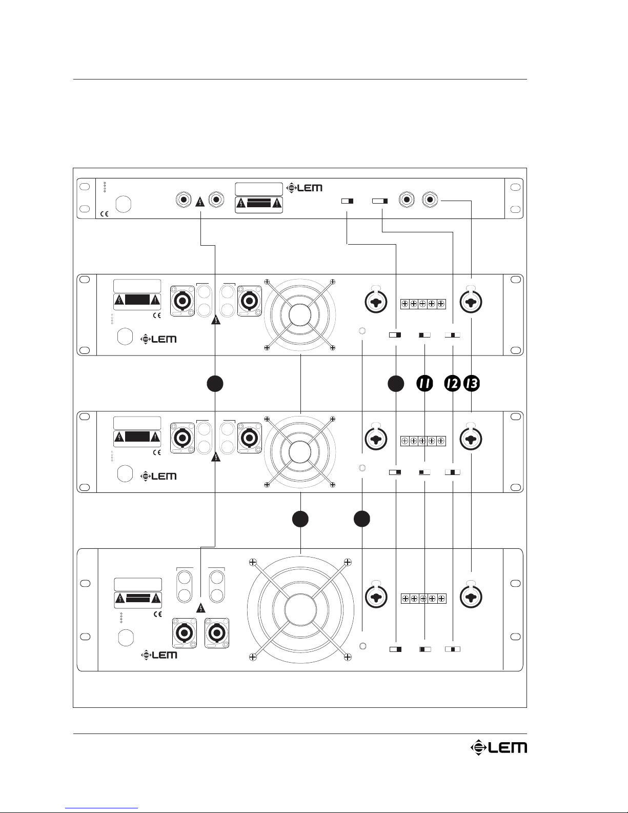
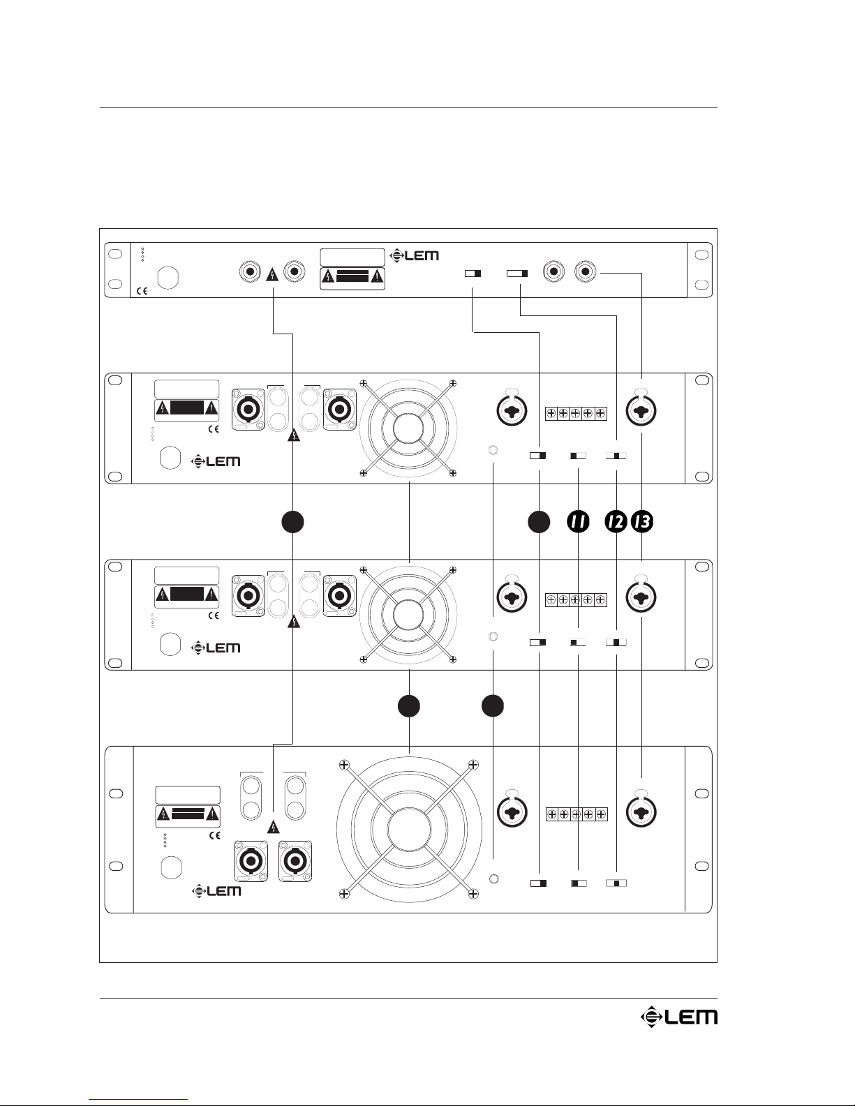
8
OUTPUTS
Uscite di potenza: uscite da collegare ai diffusori.
Le uscite A&B degli amplificatori AMP SERIES dispongono
ciascuna di un connettore SPEAKON a 4 vie e BINDING-
POST nei modelli AMP 4,8 & 12, JACK nel modello AMP 2.4.
Funzioni & controlli
Page 11
9
AMP SERIE
S
Funzioni & controlli
Collegate alle uscite dell'amplificatore solo diffusori (o
sistemi di diffusori) che rientrino nei limiti di carico di
potenza e di impedenza dichiarati per lamplificatore stesso
(vedi ê Specifiche tecniche). Usate
solo cavi per diffusori
(cavi o piattine a 2 fili, solitamente 1 rosso e 1 nero):
non usate
mai cavi schermati o cavi segnale (cavi solitamente utilizzati per
microfoni, strumenti e apparecchiature audio in genere).
9
GND
Connettore ausiliario per la messa a terra dellamplificatore.
10
GROUND ON / FLOATING
Controllo di separazione della massa elettrica dalla massa
del telaio.
Agendo su questo selettore, vi sarà spesso possibile interrompere
i loop (ricicli) di massa che si possono verificare nei
collegamenti tra più apparati, spesso causa di ronzii od altre
interferenze rumorose.
LIMITER ON/OFF
Selettore per lesclusione del limiter.
Selettore PARALLEL/STEREO/BRIDGE
Selettore delle 3 predisposizioni di funzionamento
dellamplificatore: permette di determinare come utilizzare
lamplificatore nel sistema, semplificandone notevolmente i
collegamenti con altri apparati (crossover, altri amplificatori,
casse acustiche).
Agite su questo comando
solo quando lamplificatore è
spento: agendo diversamente potreste danneggiare i
componenti delle casse acustiche.
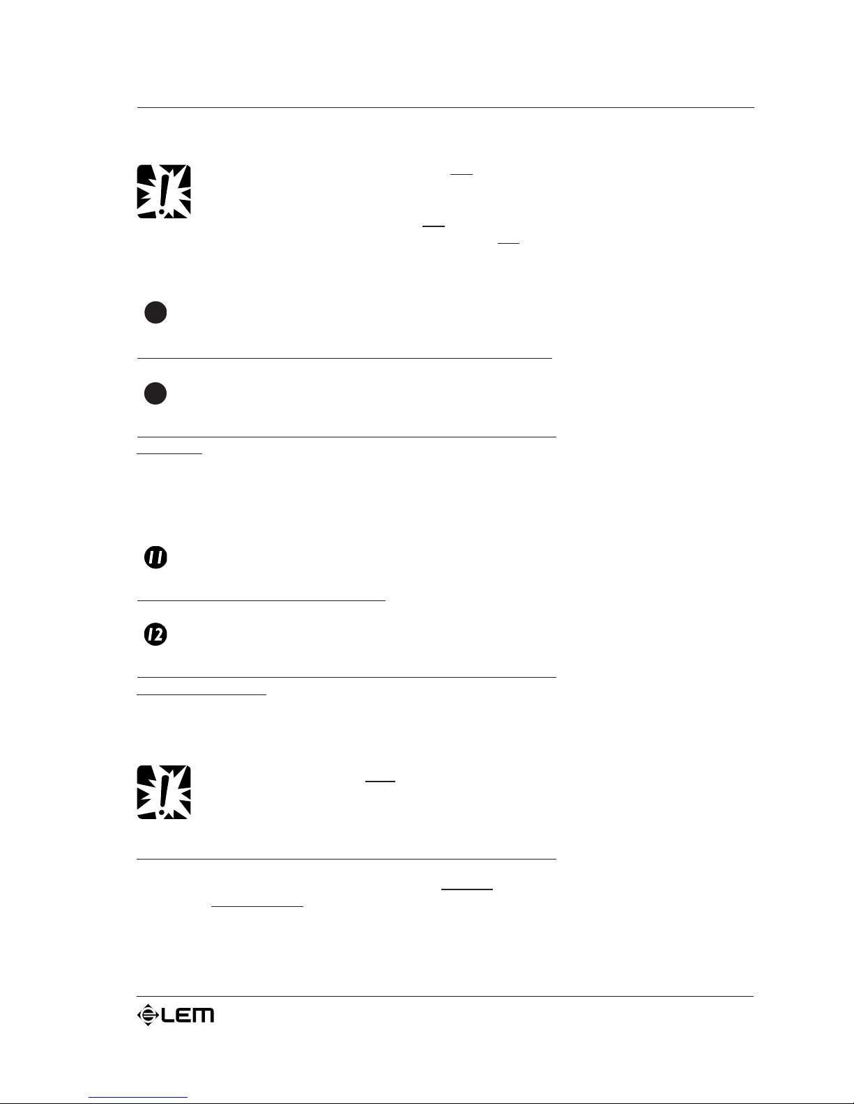
A) STEREO
Con la predisposizione STEREO, 2 segnali separati vengono
amplificati
separatamente dai canali A e B dellamplificatore.
In altre parole, un segnale collegato allingresso A viene
amplificato solo dal canale A e inviato alla sola uscita A;
Page 12
10
AMP SERIE
S
viceversa, un segnale collegato allingresso B viene amplificato solo
dal canale B e inviato alla sola uscita B.
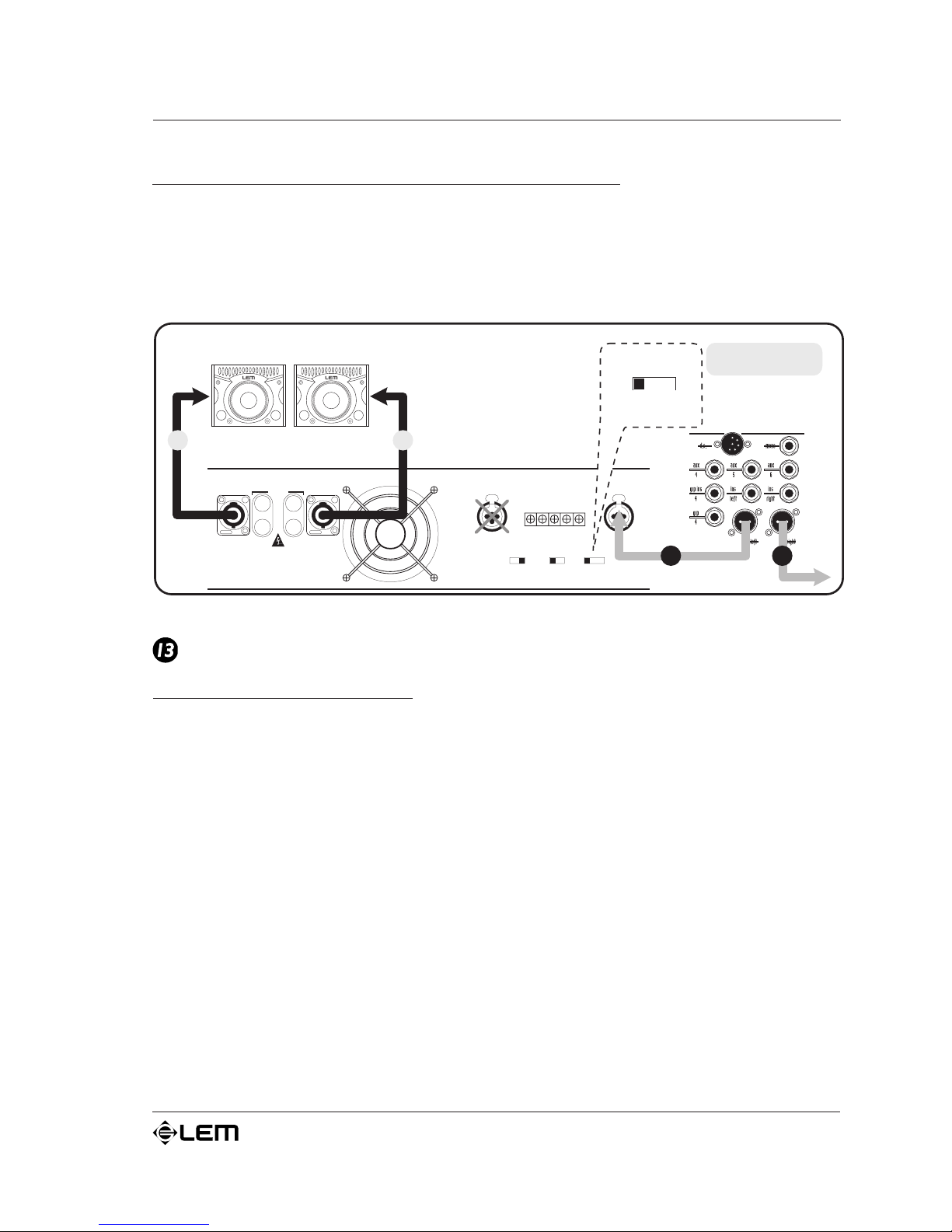
B) BRIDGE (tranne AMP 2.4)
Con la predisposizione BRIDGE (ponte) il segnale viene
amplificato dalle due sezioni A e B dellamplificatore
sommate tra
loro. In altre parole il segnale collegato all ingresso A viene:
1) amplificato da entrambe le sezioni di amplificazione
sommate
tra loro;
2) inviato ad ununica uscita (BRIDGE).
La caratteristica di questa predisposizione consiste nel fatto che
in uscita si ha un segnale con potenza e impedenza nominale
raddoppiate (vedi é SPECIFICHE TECNICHE).
Funzioni & controlli
AMPLIFIER OUTPUTS
CH 2 CH 1
MIN 4 Ohm MIN 4 Ohm
GROUND PARALLELONFLOATING
BRIDGEOFF
STEREOLIMITER
ON
BRIDGED
+
_
8 Ohm
AMPLIFIER INPUTS
CH 2
CH 2 CH 1
++
__
CH 1
GND
MIXER
SPEAKER
R
BRIDGE
PARALLEL
BRIDGE
STEREO
L
AMPLIFIER OUTPUTS
CH 2 CH 1
MIN 4 Ohm MIN 4 Ohm
GROUND PARALLELONFLOATING
BRIDGEOFF
STEREOLIMITER
ON
BRIDGED
+
_
8 Ohm
AMPLIFIER INPUTS
CH 2
CH 2 CH 1
++
__
CH 1
GND
MIXER
SPEAKERS
STEREO
R
L
L
R
PARALLEL
BRIDGE
STEREO
Page 13
11
AMP SERIE
S
Funzioni & controlli
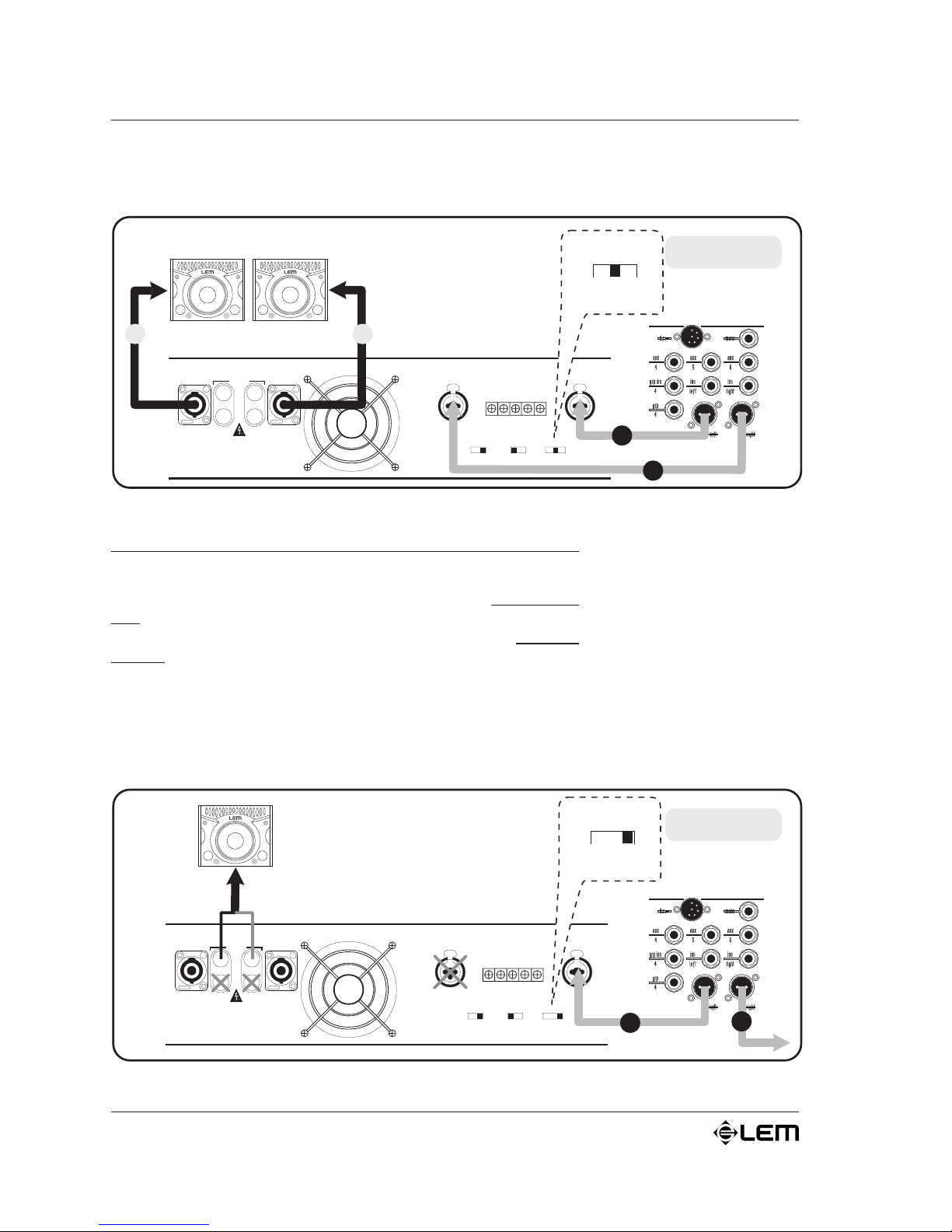
C) PARALLEL
Con la predisposizione PARALLEL un solo segnale viene
amplificato da entrambi i canali A e B dellamplificatore. In altre
parole, un segnale collegato allingresso A viene inviato sia
alluscita A che alluscita B.
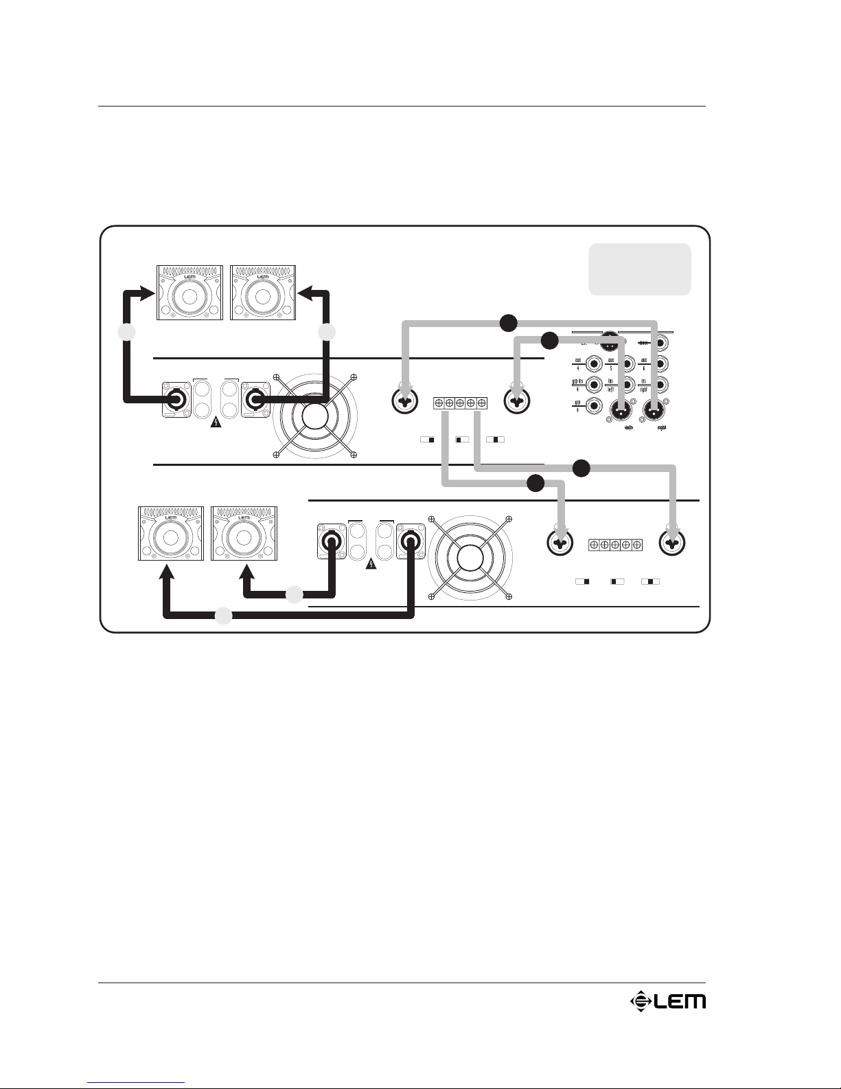
INPUTS
Ingressi bilanciati (0 dB / 30 kW): nei modelli AMP 4,8 & 12,
per ciascuno dei due canali A&B dell'amplificatore è presente
un doppio ingresso bilanciato con un connettore COMBO ed un
connettore BARRIER STRIP collegati in parallelo tra loro. In
questo modo, il segnale in ingresso nell'amplificatore può essere
collegato indifferentemente ad un connettore o allaltro e può
essere, se necessario, rilanciato verso l'ingresso di un altro
amplificatore o verso altri apparati (vedi é illustrazione).
Nel modello AMP 2.4 è presente un singolo ingresso bilanciato con
connettore JACK per ciascuno dei due canali A&B.
AMPLIFIER OUTPUTS
CH 2 CH 1
MIN 4 Ohm MIN 4 Ohm
GROUND PARALLELONFLOATING
BRIDGEOFF
STEREOLIMITER
ON
BRIDGED
+
_
8 Ohm
AMPLIFIER INPUTS
CH 2
CH 2 CH 1
++
__
CH 1
GND
PARALLEL
MIXER
R
SPEAKERS
B A
PARALLEL
BRIDGE
STEREO
L
Page 14
12
AMP SERIE
S
Funzioni & controlli
AMPLIFIER OUTPUTS
CH 2 CH 1
MIN 4 Ohm MIN 4 Ohm
GROUND PARALLELONFLOATING
BRIDGEOFF
STEREOLIMITER
ON
BRIDGED
+
_
8 Ohm
AMPLIFIER INPUTS
CH 2
CH 2 CH 1
++
__
CH 1
GND
AMPLIFIER OUTPUTS
CH 2 CH 1
MIN 4 Ohm MIN 4 Ohm
GROUND PARALLELONFLOATING
BRIDGEOFF
STEREOLIMITER
ON
BRIDGED
+
_
8 Ohm
AMPLIFIER INPUTS
CH 2
CH 2 CH 1
++
__
CH 1
GND
MIXER
SPEAKERS
L
SIGNAL
LINK
SPEAKERS
R
R
L
R
L
L
R
Page 15
13
AMP SERIE
S
Cavi di collegamento
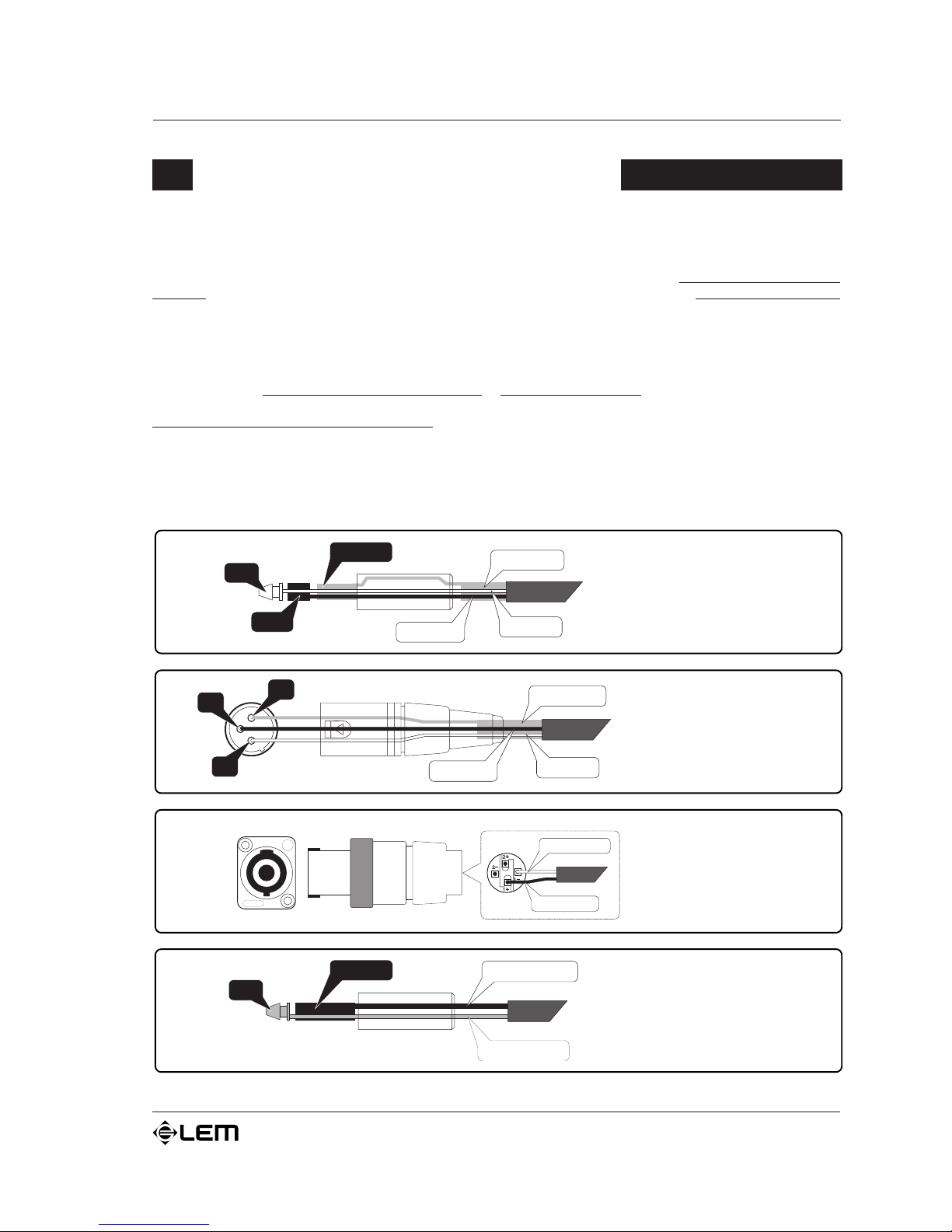
Di seguito sono riportati gli schemi di connessione dei connettori utilizzabili con gli amplificatori AMP
SERIES. Per il collegamento dellamplificatore al mixer accertatevi di utilizzare
sempre e solo cavi di
segnale (cavi schermati, costituiti da due fili più una calza che funge da schermo) e non cavi di potenza
(cavi colonna costituiti solo da due fili, in genere di sezione maggiore): lutilizzo di cavi non schermati, infatti,
potrebbe facilmente determinare linsorgere di fastidiosi ronzii e rumori di fondo. Gli ingressi degli amplificatori
AMP SERIES sono bilanciati e, pertanto, sono realizzati in modo tale che i disturbi eventualmente presenti
sulla linea vengano eliminati od almeno ridotti in larga misura. Vi consigliamo, quindi, di utilizzare, quando
possibile, per le connessioni al mixer sempre cavi bilanciati. Per il collegamento dellamplificatore alle casse,
invece, utilizzate
sempre e solo cavi di potenza e non cavi di segnale: in questultimo caso, infatti, la
potenza erogata dagli amplificatori andrebbe in parte dispersa a causa della ridotta sezione del cavo.
Abbiate cura dei cavi di collegamento, afferrandoli sempre per i connettori, evitando di tirarli lungo il
cordone ed avvolgendoli senza nodi o forti torsioni: ne allungherete la vita e laffidabilità, a vostro assoluto
vantaggio. Verificate periodicamente che i cavi che impiegate siano in buono stato, con le connessioni
realizzate nel modo corretto e con tutti i contatti in perfetta efficienza: spesso, infatti, molti problemi ed
inconvenienti (falsi contatti, rumori di massa, scariche, ecc.) sono dovuti unicamente allutilizzo di cavi inadatti
o avariati.
Cavi di collegamento
/ NEGATIVE
+
/ POSITIVE
TIP
SLEEVE
+
POSITIVE
NEGATIVE
Connettore
di potenza JACK
3
GROUND
HOT (+
)
COLD
()
1
2
Connettore
XLR-M bilanciato
TIP
RING
GROUND
HOT (+
)
SLEEVE
COLD
()
Connettore
JACK bilanciato
Connettore
di potenza
SPEAKON
Page 16
14
AMP SERIE
S
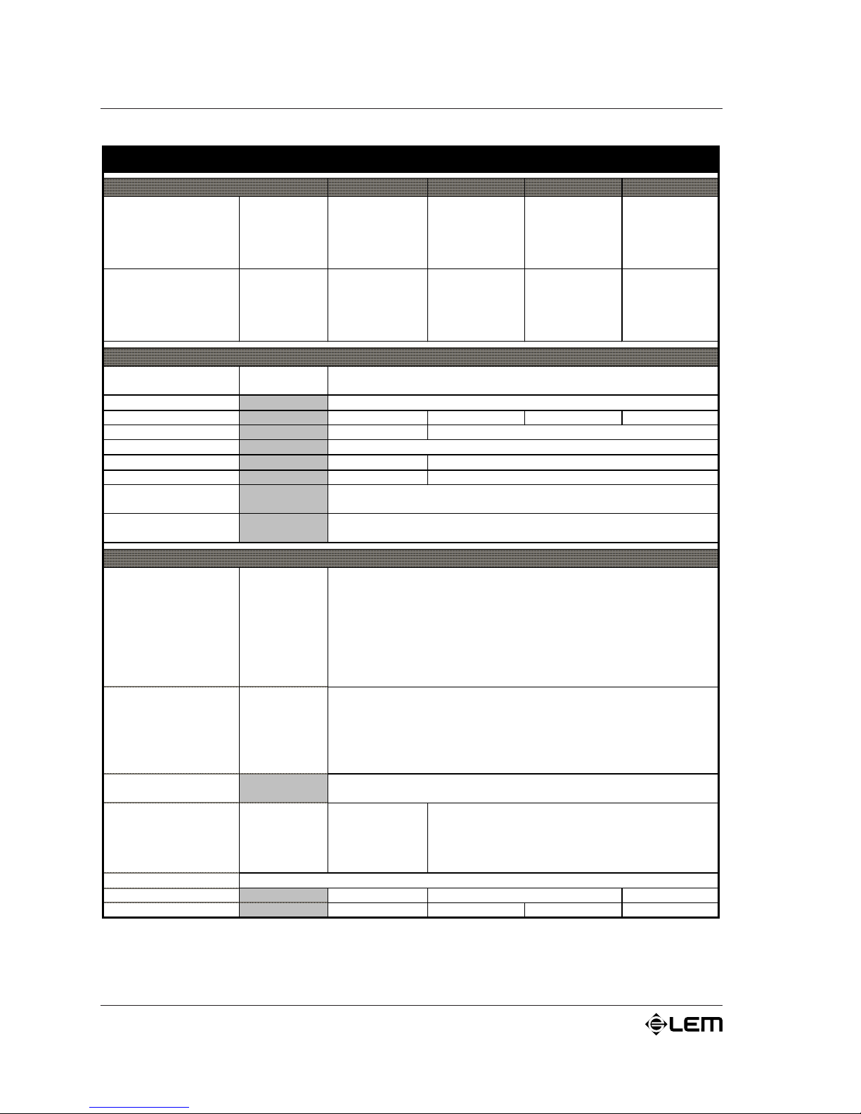
Specifiche tecniche
AMP SERIES SPECIFICHE TECNICHE
SPECIFICHE DI POTENZA AMP 2.4 AMP 4 AMP 8 AMP 12
Potenza di uscita EIA
1kHz
THD massima 1%
Entrambi i canali
2 Ohms
4Ohms
8 Ohms
4 Ohms bridged
8 Ohms brid
g
ed
---
---
120 W
---
---
300 W
230 W
150 W
540 W
420 W
550 W
425 W
270 W
1100 W
850 W
1000 W
650 W
400 W
2000 W
1300 W
Potenza di uscita FTC
20HZ-20KHz
THD massima 0,1%
Entrambi i canali
4Ohms
8 Ohms
8 Ohms bridged
---
100 W
---
200 W
400 W
400 W
800 W
600 W
1200 W
SPECIFICHE ELETTRONICHE
Ingresso
Sensibilità
Im
p
edenza
0 dB (0,775 Vrms)
20 kOhms (bilanciato) 10 kOhms (sbilanciato
)
Risposta in frequenza 20÷20000 Hz (+0, -1dB)
Guada
g
no in voltaggio 26dB 28dB 31dB 34dB
Slew rate -27 V/µs 20 V/µs
Damping factor > 200:1 (@ 1 kHz / 8Ohms)
Diafonia -100dB @ 1 kHz -90dB @ 1 kHz
Ra
pp
orto S/N > 100 dB > 105 dB
Distorsione armonica
(
THD+N
)
0.1% @1 kHz
Distorsione di
inte rmodulazione
(
IMD
)
0.1% 8 ohms, 1 kHz @ 1 W
SPECIFICHE GENERALI
PROTEZIONI
Alimentatore
Amplificatore
Diffusori
Protezione termica sul trasformatore
Protezione termica sul dissipatore
Protezione dal corto circuito
Rilevatore di corrente in uscita
Limiter
CONTROLLI
Pannello
frontale
Pannello
posteriore
Interrutore di accensione
Controllo di livello per ciascun canale
Selettore PARALLEL/STEREO/BRIDGE (AMP 2.4 STEREO/PARALLEL)
Separatore di massa Ground ON/Floating
Interrutore Limiter ON/OFF
(
eccetto AMP 2.4
)
INDICATORI
ON: 1 LED verde
PROTECT/LIMIT/SIGNAL: barra a 3 LED
p
er ogni canale
CONNETTORI
Ingresso
Uscita
1 JA CK per ciascun canale
1 JACK STEREO per cuffia
1 JA CK per ciascun canale
1 COMBO + Barrier strip in parallelo per ogni canale
1 SPEAKON 4-vie + 2 Binding-Post per ogni canale
ALIMENTAZIONE vedi targhetta informativa sull'apparato
DIMENSIONI
(
LxAxP
)
483x44x310 mm 483x88x442 mm 483x132x442 mm
PESO 8 kg 12,5 kg 15 kg 18,5 kg
Page 17

1
AMP SERIE
S
Contents
Introduction . . . . . . . . . . . . . . . . . . . . . . . . . . . . . . . . . . . . . . . . 2
Installation & operating instructions . . . . . . . . . . . . . . . . . . . . . 3
Functions & controls . . . . . . . . . . . . . . . . . . . . . . . . . . . . . . . . . . 5
PROTECT LEDs . . . . . . . . . . . . . . . . . . . . . . . . . . . . . . . . . . . . . . . . . . . . . 7
LIMIT LEDs . . . . . . . . . . . . . . . . . . . . . . . . . . . . . . . . . . . . . . . . . . . . . . . . 7
SIGNAL LEDs . . . . . . . . . . . . . . . . . . . . . . . . . . . . . . . . . . . . . . . . . . . . . . 7
LEVEL . . . . . . . . . . . . . . . . . . . . . . . . . . . . . . . . . . . . . . . . . . . . . . . . . . . . 8
PHONES . . . . . . . . . . . . . . . . . . . . . . . . . . . . . . . . . . . . . . . . . . . . . . . . . . 8
AIR VENTS . . . . . . . . . . . . . . . . . . . . . . . . . . . . . . . . . . . . . . . . . . . . . . . . 8
POWER ON. . . . . . . . . . . . . . . . . . . . . . . . . . . . . . . . . . . . . . . . . . . . . . . . 8
OUTPUTS . . . . . . . . . . . . . . . . . . . . . . . . . . . . . . . . . . . . . . . . . . . . . . . . . 8
GND . . . . . . . . . . . . . . . . . . . . . . . . . . . . . . . . . . . . . . . . . . . . . . . . . . . . . 9
GROUND ON / FLOATING . . . . . . . . . . . . . . . . . . . . . . . . . . . . . . . . . . . . 9
LIMITER ON/OFF . . . . . . . . . . . . . . . . . . . . . . . . . . . . . . . . . . . . . . . . . . . 9
PARALLEL/STEREO/BRIDGE selector . . . . . . . . . . . . . . . . . . . . . . . . . . . . . 9
INPUTS . . . . . . . . . . . . . . . . . . . . . . . . . . . . . . . . . . . . . . . . . . . . . . . . . . 11
Connector cables . . . . . . . . . . . . . . . . . . . . . . . . . . . . . . . . . . . 12
Technical specifications . . . . . . . . . . . . . . . . . . . . . . . . . . . . . . 13
Contents
Page 18

2
AMP SERIE
S
Congratulations for having chosen a AMP SERIES power amplifier!
AMP SERIES are compact, high-powered amplifiers designed to meet the most various
requirements in the sound amplification field.
AMP SERIES amplifiers have been designed using a structural concept based on the following
premises:
a) rise in efficiency, thus drop in wasted power.
b) an efficient protection system able to effectively protect the amplifier itself and the loudspeakers
connected to it, enabling it to stand up to rough treatment in conditions of complete safety.
c) greater reduction in structure size, favoring better price/performance ratio.
This particular structure has enabled considerable results to be achieved, such as high power
from compact, lightweight units and great dynamic capacity combined with tone quality and
absolute reliability.
The AMP SERIES amplifiers are available in four different models:
AMP 1
2
ê 600+600 Watts / 4W BRIDGE 1300 Watts / 8W
AMP
8
ê 400+400 Watts / 4W BRIDGE 850 Watts / 8W
AMP
4
ê 200+200 Watts / 4W BRIDGE 420 Watts / 8W
AMP 2.
4
ê 120+120 Watts / 8W
Quality connectors (SPEAKON for power output, except for AMP 2.4), knobs, switches and
the strong metal frame fitted with handles have been designed to withstand heavy use without
any problem.
The LEDs display gives precise information on the current status of the signal in any lighting
condition.
The AMP SERIES is suitable to all the kinds of use in which powerful, versatile and reliable
amplifiers are required, with compact dimensions and an better price/performance ratio:
from the systems of movable amplification to the fixed installations, from the systems of multiamplification to the homes setups.
Itroduction
Introduction
Page 19

3
AMP SERIE
S
Installation & operating instructions
Installation & operating instructions
PMains Power Connection.
Before connecting the amplifier to the mains power socket, make certain that the voltage
corresponds with that indicated on the rear of the unit (an allowance of ±10% is
acceptable).
Before connecting the power cable to the mains, always make certain that it is not damaged
and that there are no bare wires. Always connect the power cable to the amplifier
before
switching it on and only remove the cable
after switching it off.
PSwitching on and off.
In an audio system, its always better to switch power amplifiers
on last and off first.
Remember to
switch off the amplifier before connecting it to or disconnecting it from other units and to
switch always on
first the mixer and then the amplifier: in this manner, peaks which are annoying and
sometimes dangerous particularly for the loudspeakers enclosures are avoided.
It is normal for the LEDs to light up for a few moments when switching on.
P Handling.
Do not force knobs and connectors, as they could be damaged if treated with excessive force.
PConnections and prevention of possible interference.
Avoid installing your equipment near radios, televisions, etc., since they could cause noisy disturbance. When
connecting the other units in your sound system, watch out for to so-called earth-loops, which can cause
hum: in the event of interference, try using the EARTH switch on the amplifiers rear panel
PConnector cables.
To connect the amplifier to the mixer, always make certain to use
only signal cables (screened cables
made up of two wires plus a braid screen),
not power cables (speaker cables, normally made up of two
wires, usually with a greater cross-section): to connect the amplifier to the loudspeaker enclosures,
always
use power cables, not signal cables, as in the latter case in fact, the power from the amplifiers would
be partially dispersed because of the cables smaller cross-section.
Take care of the connector cables. Always hold them by the connectors, avoiding pulling the wire and avoid
knots and twists when coiling them: this gives the advantage of increasing their life and reliability.
PAir circulation for cooling.
Amplifiers correct cooling is ensured by an internal fan, the speed of which is controlled by a special sensor
(the speed is proportional to the output power and therefore the temperature generated): remember never
to block the air vents located on the units sides in any way: the air necessary for cooling passes through
these.
If the amplifier is kept in a flight-case during use, make certain that it has sufficient openings at both the
amplifiers air vents. Avoid locating it in very small spaces which dont allow correct air circulation.
Page 20

4
AMP SERIE
S
PProtection and maintenance.
Avoid exposing the amplifier to direct sun, strong heat, intense vibrations, very dusty or damp surroundings,
or even worse, rain: this will avoid eventual malfunction, deterioration or even electric shocks and fires.
In the event of a breakdown, do not open the amplifier contact the nearest GENERALMUSIC Service
Centre.
PConservation of documents and packing.
Keep this manual for future consultation. On this subject, remember that equipment always gets a better
price on the secondhand market if it has all its original documentation and packing as well as being wellkept.
Installation & operating instructions
Page 21
5
AMP SERIE
S
Functions & controls
Functions & controls
POWER
AMP 4
16
16
-0
-0
0
0
18
18
32
32
56
56
40
40
22
22
26
26
0
0
12
12
2
2
10
10
6
6
4
4
8
8
14
14
PROTECT
PROTECT
LIMIT
LIMIT
SIGNAL
SIGNAL
CH 1
CH 2
HEAVY DUTY POWER AMPLIFIER
PROTECT
CLIP
SIGNAL
CHANNEL 1
PROTECT
CLIP
SIGNAL
CHANNEL 2
POWER
AMP 2.4
PHONES
16
-0
0
18
32
56
40
22
26
0
12
2
10
6
4
8
14
16
-0
0
18
32
56
40
22
26
0
12
2
10
6
4
8
14
HEAVY DUTY POWER AMPLIFIER
POWER
AMP 8
16
16
-0
-0
0
0
18
18
32
32
56
56
40
40
22
22
26
26
0
0
12
12
2
2
10
10
6
6
4
4
8
8
14
14
PROTECT
PROTECT
LIMIT
LIMIT
SIGNAL
SIGNAL
CH 1
CH 2
HEAVY DUTY POWER AMPLIFIER
POWER
AMP 12
HEAVY DUTY POWER AMPLIFIER
16
16
-0
-0
0
0
18
18
32
32
56
56
40
40
22
22
26
26
0
0
12
12
2
2
10
10
6
6
4
4
8
8
14
14
PROTECT
PROTECT
LIMIT
LIMIT
SIGNAL
SIGNAL
CH 1
CH 2
1
2
3
4
5
6
7
Page 22
6
AMP SERIE
S
Functions & controls
100V50/60Hz
120V50/60Hz
230V50/60Hz
240V50/60Hz
AMPLIFIER OUTPUTS AMPLIFIERINPUTS
CH 2 CH2
GROUND PARALLELFLOATING
STEREO
ON
CH 1
MIN.LOAD
8Ohm
CH 1
AC
~
AVIS:
RISQUEDE CHOC ELECTRIQUE-NE PAS OUVRIR
RISKOF ELECTRIC SHOCK
DONOT OPEN
CAUTION
"WARNING"
TOREDUCE THE RISK OF
FIREOR ELECTRIC SHOCK DONOT EXPOSE
THISPRODUCT TO RAIN OR MOISTURE.
AMP 2.4
HEAVYDUTY POWER AMPLIFIER
BY
GENERALMUSICs.p.a.
MADEIN CHINA
100V50/60Hz
120V50/60Hz
230V50/60Hz
240V50/60Hz
AMPLIFIER OUTPUTS
AMPLIFIER INPUTS
CH 2 CH 1
MIN4 Ohm MIN4 Ohm
CH 2
CH 2
GND
CH 1
GROUND PARALLELONFLOATING
BRIDGEOFF
STEREOLIMITER
ON
BRIDGED
+
++
_
__
8Ohm
CH 1
GND
AC
~
AVIS:
RISQUEDE CHOC ELECTRIQUE-NE PAS OUVRIR
RISKOF ELECTRIC SHOCK
DONOT OPEN
CAUTION
"WARNING"
TOREDUCE THE RISK OF
FIREOR ELECTRIC SHOCK DONOT EXPOSE
THISPRODUCT TO RAIN OR MOISTURE.
BY
GENERALMUSICs.p.a.
MADEIN CHINA
AMP 12
HEAVYDUTY POWER AMPLIFIER
100V50/60Hz
120V50/60Hz
230V50/60Hz
240V50/60Hz
AMPLIFIER OUTPUTS
CH 2 CH 1
MIN4 Ohm MIN4 Ohm
GND
GROUND PARALLELONFLOATING
BRIDGEOFF
STEREOLIMITER
ON
BRIDGED
+
_
8Ohm
AC
~
BY
GENERALMUSICs.p.a.
AVIS:
RISQUEDE CHOC ELECTRIQUE-NE PAS OUVRIR
RISKOF ELECTRIC SHOCK
DONOT OPEN
CAUTION
"WARNING"
TOREDUCE THE RISK OF
FIREOR ELECTRIC SHOCK DONOT EXPOSE
THISPRODUCT TO RAIN OR MOISTURE.
MADEIN CHINA
AMP 4
HEAVYDUTY POWER AMPLIFIER
AMPLIFIER INPUTS
CH 2
CH 2 CH 1
++
__
CH 1
GND
100V50/60Hz
120V50/60Hz
230V50/60Hz
240V50/60Hz
AMPLIFIER OUTPUTS
CH 2 CH 1
MIN4 Ohm MIN4 Ohm
GND
GROUND PARALLELONFLOATING
BRIDGEOFF
STEREOLIMITER
ON
BRIDGED
+
_
8Ohm
AC
~
BY
GENERALMUSICs.p.a.
AVIS:
RISQUEDE CHOC ELECTRIQUE-NE PAS OUVRIR
RISKOF ELECTRIC SHOCK
DONOT OPEN
CAUTION
"WARNING"
TOREDUCE THE RISK OF
FIREOR ELECTRIC SHOCK DONOT EXPOSE
THISPRODUCT TO RAIN OR MOISTURE.
MADEIN CHINA
AMP 8
HEAVYDUTY POWER AMPLIFIER
AMPLIFIER INPUTS
CH 2
CH 2 CH 1
++
__
CH 1
GND
8
9
10
6
Page 23

7
AMP SERIE
S
1
PROTECT LEDs
Protection pilot lights.
If these LEDs light up, this indicates that one of the various
protections safeguarding the different sections of the amplifier and
the loudspeaker enclosures has tripped due to an operating fault.
In these cases, the power output is normally switched off until
normal operating conditions are restored.
The following is a description of all the P SERIES protections:
1) LOUDSPEAKER PROTECTION: in the event of malfunction,
a sensor located on the power outputs is able to break the circuit
avoiding that current peaks reach the speakers and damage them
2) THERMAL PROTECTION ON THE HEATSINK: this
protection intervene whenever there is an excessive rise in
temperature of the internal heatsink.
3) SHORT CIRCUIT PROTECTION: trips in the event of a short-
circuit or overload, limiting the output current.
Some protection situations require the amplifier to be switched off and
then back on for normal operating conditions to be restored.
2
LIMIT LEDs
Amplifier status indicators: these are LEDs able to indicate,
for channels A and B, the operation of the internal limiter, when
inserted, or the clipping of the amplifier.:
These 2 LEDs are POST-LEVEL: in other words they display the
status of the signal when it has already been regulated by the input
level controls.
3
SIGNAL LEDs
Signal status indicators: these are LEDs able to indicate, for
channels A and B, a signal presence in the inputs of the amplifier.
4
LEVEL
Control of the input level of the external signal: operates with
continual values which vary from
fully closed (position ¥ -
Functions & controls
Page 24

8
AMP SERIE
S
the signal is not fed to the amplifier sections) to fully open
(position 0dB - the signal is sent to the amplifier sections at the
same level as that with which it arrives at the input). In other
words, this control operates as an attenuator of the signal fed to
the amplifier.
5
PHONES
STEREO headphone output: the AMP 2.4 has an output to
which STEREO headphones with a minimum impedance of 200W can
be connected. When the headphones are connected to this output,
the amplifiers main outputs are automatically disabled, so the input level
controls can be used as headphone volume controls.
6
AIR VENTS (AMP 4,8 & 12)
Amplifier cooling system air vents.
The fan of the AMP SERIES cooling system create a flow of air
with front-to-back direction: this means that the air is taken from
the opening on the front and, after having cooled the heat sinks
and mains transformer, is expelled through the opening on the back
side. Care must always be taken to avoid blocking these openings
and to never place the amplifier in a position which does not allow
sufficient air circulation.
7
POWER ON
ON/OFF switch with indication LED.
8
OUTPUTS
Power out: outputs to be connected to the loudspeaker enclosures.
AMP SERIES amplifiers A&B outputs both have a 4-way
SPEAKON and a BINDING-POST connectors in AMP 4,8 &
12 models and a JACK in the AMP 2.4.
Only loudspeaker enclosures (or loudspeaker enclosure systems)
within the amplifiers declared power and impedance load range
should be connected to the amplifiers outputs (see ê Technical
specifications).
Use
only speaker cables (two-core cables, normally with a red and a black
wire): do
not use screened or signal cables (cables normally used for
microphones, instruments and audio equipment in general).
Functions & controls
Page 25
9
AMP SERIE
S
Functions & controls
9
GND
Auxiliary connector for the earth of the amplifier.
10
GROUND ON / FLOATING
Controls the separation of the electrical earth from that of the
chassis. Using this selector, it is often possible to break earth
loops which can form when several units are connected together
and which can cause hum or other noises
LIMITER ON/OFF
Limiter ON/OFF selector.
PARALLEL/STEREO/BRIDGE selector
Selector for the amplifiers 3 operating settings: allows to
decide how to use the amplifier in the audio setup, considerably
simplifying the connections with other units (crossovers, other
amplifiers, loudspeaker enclosures).
This control should
only be used when the amplifier is off,
otherwise the loudspeakers components could be damaged.
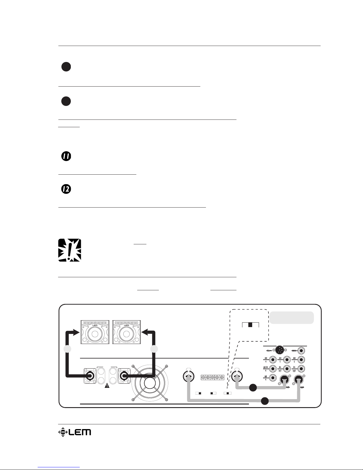
A) STEREO
With the STEREO setting, 2 separate signals are treated separately
by channels A and B of the amplifier.
AMPLIFIER OUTPUTS
CH 2 CH 1
MIN 4 Ohm MIN 4 Ohm
GROUND PARALLELONFLOATING
BRIDGEOFF
STEREOLIMITER
ON
BRIDGED
+
_
8 Ohm
AMPLIFIER INPUTS
CH 2
CH 2 CH 1
++
__
CH 1
GND
MIXER
SPEAKERS
STEREO
R L
L
R
PARALLEL
BRIDGE
STEREO
Page 26
10
AMP SERIE
S
In other words, a signal connected to input A is only treated by
channel A of the amplifier and only fed to output A and a signal
connected to input B is only treated by channel B of the amplifier and
only fed to output B.
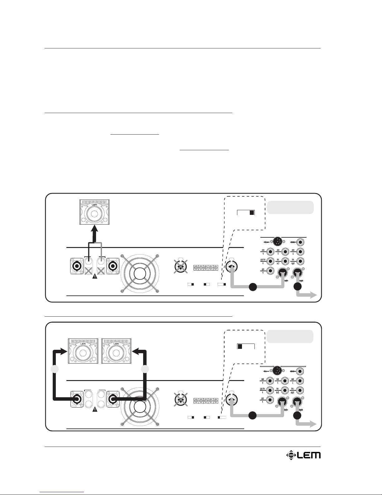
B) BRIDGE (except AMP 2.4)
With the BRIDGE setting signal is amplified by the two sections
(A&B) of the amplifier
summed together. In other words the signal
connected to input A is:
1) amplified by both the amplification sections summed together;
2) fed to a single output (BRIDGE).
The characteristic of this setting consists in the fact that there is
a signal fed out with double the power and rated impedance (see
é TECHNICAL SPECIFICATIONS).
C) PARALLEL
Functions & controls
AMPLIFIER OUTPUTS
CH 2 CH 1
MIN 4 Ohm MIN 4 Ohm
GROUND PARALLELONFLOATING
BRIDGEOFF
STEREOLIMITER
ON
BRIDGED
+
_
8 Ohm
AMPLIFIER INPUTS
CH 2
CH 2 CH 1
++
__
CH 1
GND
MIXER
SPEAKER
R
BRIDGE
PARALLEL
BRIDGE
STEREO
L
AMPLIFIER OUTPUTS
CH 2 CH 1
MIN 4 Ohm MIN 4 Ohm
GROUND PARALLELONFLOATING
BRIDGEOFF
STEREOLIMITER
ON
BRIDGED
+
_
8 Ohm
AMPLIFIER INPUTS
CH 2
CH 2 CH 1
++
__
CH 1
GND
PARALLEL
MIXER
R
SPEAKERS
B A
PARALLEL
BRIDGE
STEREO
L
Page 27
11
AMP SERIE
S
Functions & controls
With the PARALLEL setting, one signal is treated by both channel
A and B of the amplifier. In other words a signal connected to
input A is sent to both output A and output B.
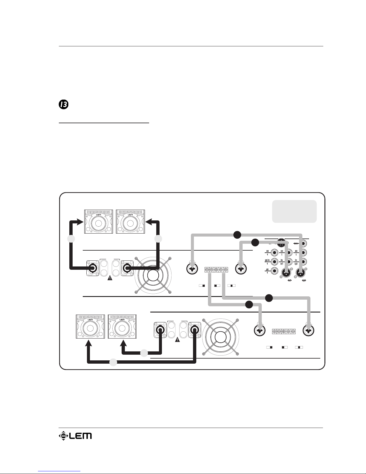
INPUTS
Balanced inputs (0 dB/30 kW): in AMP 4,8 & 12 models both
channel A&B of the amplifier have a double balanced input with
an COMBO connector and a BARRIER STRIP connector connected
in parallel. In this manner, the amplifiers input signal can be
connected to either of these connectors (greatly facilitating
connections) and if necessary, can be passed on to the input of
another amplifier or other units (see é illustrations).
On the AMP 2.4, there is a single balanced input with a JACK
connector for each of the A&B channels.
AMPLIFIER OUTPUTS
CH 2 CH 1
MIN 4 Ohm MIN 4 Ohm
GROUND PARALLELONFLOATING
BRIDGEOFF
STEREOLIMITER
ON
BRIDGED
+
_
8 Ohm
AMPLIFIER INPUTS
CH 2
CH 2 CH 1
++
__
CH 1
GND
AMPLIFIER OUTPUTS
CH 2 CH 1
MIN 4 Ohm MIN 4 Ohm
GROUND PARALLELONFLOATING
BRIDGEOFF
STEREOLIMITER
ON
BRIDGED
+
_
8 Ohm
AMPLIFIER INPUTS
CH 2
CH 2 CH 1
++
__
CH 1
GND
MIXER
SPEAKERS
L
SIGNAL
LINK
SPEAKERS
R
R
L
R
L
L
R
Page 28
12
AMP SERIE
S
Connector cables
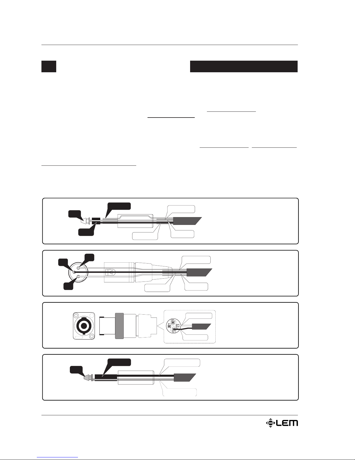
The following diagrams illustrate the wiring of the various types of sockets that can be used with the AMP
SERIES power amplifiers.
To connect the amplifier to the mixer, always make certain to use
only signal cables (screened cables
made up of two wires plus a braid screen),
not power cables (speaker cables, normally made up of two
wires, usually with a greater cross-section): the use of unscreened cables could in fact cause annoying buzzes
and background noise. The P SERIES amplifiers inputs are in fact balanced and therefore designed in
such a way that any interference on the line is eliminated or at least greatly reduced. We therefore always
suggest the use of balanced cables for microphones and line units whenever possible.
To connect the amplifier to the loudspeaker enclosures, always use
only power cables, not signal cables,
as in the latter case in fact, the power from the amplifiers would be partially dispersed because of the
cables smaller cross-section.
Take care of the connector cables. Always hold them by the connectors, avoiding pulling the wire and
avoid knots and twists when coiling them: this gives the advantage of increasing their life and reliability.
Check your cables periodically, making certain that they are in good condition, that the connectors are
correctly wired and contacts perfectly efficient: in fact, many problems and setbacks (faulty contacts, ground
hum, disturbance, etc.) are due to the use of unsuitable of faulty cables.
Connector cables
/ NEGATIVE
+
/ POSITIVE
TIP
SLEEVE
+
POSITIVE
NEGATIVE
JACK
power connector
3
GROUND
HOT (+
)
COLD
()
1
2
Balanced
XLR-M connector
TIP
RING
GROUND
HOT (+
)
SLEEVE
COLD
()
Balanced
JACK connector
SPEAKON
power
connector
Page 29
13
AMP SERIE
S
Technical specifications
AMP SERIES TECHNICAL SPECIFICATIONS
POWER SPECIFICATIONS AMP 2.4 AMP 4 AMP 8 AMP 12
EIA output power
1kHz
Max THD 1%
Both channels driven.
2 Ohms
4Ohms
8 Ohms
4 Ohms bridged
8 Ohms bridged
---
---
120 W
---
---
300 W
230 W
150 W
540 W
420 W
550 W
425 W
270 W
1100 W
850 W
1000 W
650 W
400 W
2000 W
1300 W
FTC output powe r
20Hz20kHz
Max THD 0.1%
Both channels driven.
4Ohms
8 Ohms
8 Ohms bridged
---
100 W
---
200 W
400 W
400 W
800 W
600 W
1200 W
ELECTRICAL SPECIFICATIONS
Inputs
Sensitivity
Im
p
edance
0 dB (0,775 Vrms)
20 kOhms (balanced) 10 kOhms (unbalanced
)
Frequency response 20÷20000 Hz (+0, -1dB)
Volta
ge g
ain 26dB 28dB 31dB 34dB
Slew rate -27 V/µs 20 V/µs
Damping factor > 200:1 (@ 1 kHz / 8Ohms)
Crosstalk -100dB @ 1 kHz -90dB @ 1 kHz
Hum & Noise > 100 dB > 105 dB
Total harmonic dist ort ion
(
THD+N
)
0.1% @1 kHz
Inter-modulation distortion
(
IMD
)
0.1% 8 ohms, 1 kHz @ 1 W
GENERAL SPECIFICATIONS
PROTECTIONS
Power Supply
Amplifier
Speakers
Power transformer thermal protection
Heat sink thermal protection
Short circuit protection
Sensor for current on outputs
Limiter
CONTROLS
Front panel
Back panel
ON/OFF switch
Signal level control for each channel
PARALLEL/STEREO/BRIDGE selector (AMP 2.4 STEREO/PARALLEL)
Ground ON/Floating
Limiter ON/OFF switch
(
except AMP2.4
)
INDICATORS
ON: 1 green LED
PROTECT/LIMIT/SIGNAL: 3 LED bar for each channel
CONNECTORS
Input
Output
1 JA CK for each channel
1 headphones STE REO J ACK
1 JA CK for each channel
1 COMBO + Barrier strip in parallel for each channel
1 SPEAKON 4-way + 2 Binding-Post for each channel
POWER SUPPLY see label on the apparatus
DIMENSIONS
(
WxHxD
)
483x44x310 mm 483x88x442 mm 483x132x442 mm
WEIG HT 8 kg 12,5 kg 15 kg 18,5 kg
Page 30

Le informazioni contenute in questo documento sono state attentamente redatte e controllate.
Tuttavia non è assunta alcuna responsabilità per eventuali inesattezze.
Tutti i diritti sono riservati e questo documento non può essere copiato, fotocopiato, riprodotto
per intero o in parte senza previo consenso scritto della GENERALMUSIC S.p.A.
GENERALMUSIC si riserva il diritto di apportare senza preavviso cambiamenti e modifiche
estetiche, funzionali o di design a ciascun proprio prodotto.
GENERALMUSIC non assume alcuna responsabilità sulluso o sullapplicazione dei prodotti o
dei circuiti qui descritti.
STAMPATO IN ITALIA
The information contained in this publication has been carefully prepared and checked. However no
responsibility will be taken for any errors.
All rights are reserved and this document cannot be copied, photocopied or reproduced in part or
completely without written consent being obtained in advance from GENERALMUSIC S.p.A.
GENERALMUSIC reserves the right to make any aesthetic, functional or design modification to any
of its products without any prior notice.
GENERALMUSIC assumes no responsibility for the use or application of the products or circuits
described herein.
PRINTED IN ITALY
FEDERAL COMMUNICATIONS COMMISSION
NOTE: This equipment has been tested and found to comply with the limits for a Class A
digital device, pursuant to Part 15 of FCC Rules. These limits are designed to provide
reasonable protection against harmful interference when the equipment is operated in a
commercial environment. This equipment generates, uses and can radiate radio frequency
energy and, if not installed and used in accordance with the instruction manual, may cause
harmful interference to radio communications. Operations of this equipment in a residential
area is likely to cause harmful interference in which case the user will be required to correct
the interference at his own expense.
CAUTION: Changes or modifications to this product not expressly approved by the
manufacturer could void the user's authority to operate this product.
Page 31

 Loading...