

LELY Tigo 35 S Classic, Tigo 35 ST Classic, Tigo 40 S, Tigo 50 ST, Tigo 35 S Operator's Manual
...Page 1

Lely Tigo
S
L-H007-1104EN
Operator Manual
Page 2

TRADEMARKS, COPYRIGHT AND
DISCLAIMER
Lely, Astronaut, Astri, Atlantis, Attis, AWS, C4C, Calm, Commodus,
Compedes,
Hubble, Juno, L4C, Lely Center, Lelywash, Lotus, Luna, Nautilus, Orbiter,
Qwes, SAE, Shuttle, Splendimo, Storm, T4C, Tigo, Viseo, Voyager, Walkway
and Welger are registered trademarks of the Lely Group. The right of exclusive
use belongs to the companies of the Lely Group. All rights reserved. The
information given in this publication is provided for information purposes only
and does not constitute an offer for sale. Certain products may not be available
in individual countries and products supplied may differ from those illustrated.
No part of this publication may be copied or published by means of printing,
photocopying, microfilm or any other process whatsoever without prior
permission in writing by Lely Holding S.à r.l. Although the contents of this
publication have been compiled with the greatest possible care, Lely cannot
accept liability for any damage that might arise from errors or omissions in this
publication.
The English language manual is the original manual. Translations into other
languages use the English language manual as the source document. Lely
accepts no liability for discrepancies between the original English language
manual and versions in other languages. If there is a conflict over the content
and accuracy of any translated manual, the English language manual is the
authority document.
Cosmix, Discovery, F4C, Fertiliner, Gravitor, Grazeway, Hibiscus,
Manual Contents
Copyright © 2010 Lely Industries NV
All rights reserved
Lely Industries NV
Weverskade 110
3147 PA Maassluis
The Netherlands
Phone: +31 (0)10 59 96 333
Fax: +31 (0)10 59 96 444
Website: www.lely.com
PREFACE
This manual contains the information necessary to operate the Lely Tigo. It
also includes maintenance information that can be done by an operator.
Study and understand this information thoroughly before you operate the Lely
Tigo. Failure to do so could result in personal injury or damage to equipment.
Please consult your local Lely service provider if you do not understand the
information in this manual, or if you need additional information.
All information in this manual has been compiled with care. Lely shall not be
liable for errors or faults in this manual. The recommendations are meant to
serve as guidelines. All instructions, pictures and specifications in this manual
ii
Page 3

Warranty Conditions
Registration
are based on the latest information that was available at the time of publication.
Your Lely Tigo may comprise improvements, features or options that are not
covered in this manual.
For those parts that fail under normal operating conditions, the factory will
make replacement parts available, free of charge, for a period of 12 (twelve)
months from the date of purchase.
warranty shall not apply if the instructions mentioned in this manual have
The
not been followed, or if they have not been followed completely or correctly.
Nor will the warranty apply if you or third parties modify the machine without
our foreknowledge and/or authorisation.
The Serial Number Plate is on the right front of the main frame.The serial
number is also stamped on the front of the main frame.
Always include the serial numbers of your product when you contact your local
Lely service provider or order spare parts.
Serial Number Plate
We suggest you complete the table below with the model type, serial number
and tyre size of your product. This makes sure you can easily find the
information.
Model
Serial number
Tyre size
iii
Page 4

iv
Page 5

Table of Contents
1.
Introduction.........................................................................................................................................1-1
1.1 Introduction..............................................................................................................................1-1
1.2 Drawbar....................................................................................................................................1-3
1.3 Pick-up Unit..............................................................................................................................1-4
1.4 Cutting Unit..............................................................................................................................1-5
1.5 Carriage...................................................................................................................................1-7
1.5.1 Superstructure.........................................................................................................................1-7
1.5.2 Floor Conveyor...................................................................................................................... 1-10
1.5.3 Tailgate..................................................................................................................................1-12
1.5.4 Under-carriage.......................................................................................................................1-14
1.6 Hydraulic System...................................................................................................................1-16
1.7 Drive System..........................................................................................................................1-17
1.8 Control Panel......................................................................................................................... 1-19
1.8.1 Hydraulic Control Panel.........................................................................................................1-19
1.8.2 Comfort System.....................................................................................................................1-21
1.9 Optional Extras.......................................................................................................................1-23
1.9.1 Lely Grinder........................................................................................................................... 1-23
2. Safety...................................................................................................................................................2-1
L-H007-1104EN
2.1 Signal Words............................................................................................................................2-1
2.2 Safety Instructions....................................................................................................................2-1
2.3 Explanation of the Safety Decals.............................................................................................2-3
3. First Use..............................................................................................................................................3-1
3.1 Finish the Superstructure.........................................................................................................3-1
3.2 Adjust the Length of the PTO Shaft.........................................................................................3-2
3.3 Install the PTO Shaft with the Overload Protection..................................................................3-3
3.4 Adjust the Height of the Drawbar.............................................................................................3-4
3.4.1 Drawbar with Spindle...............................................................................................................3-5
3.4.2 Drawbar with Hydraulic Ram...................................................................................................3-6
3.5 Adapt the Electric Power Connection.......................................................................................3-7
3.6 Connect the Electric Cables.....................................................................................................3-8
3.7 Adjust the Load Sense Adjustment Screw...............................................................................3-9
3.8 Examine the Lever Setting of the ALB...................................................................................3-10
4. Before Operation................................................................................................................................4-1
4.1 At First......................................................................................................................................4-1
Table of Contents v
Page 6

4.2 Connect the Cables and Hoses to the Tractor.........................................................................4-2
4.3
Connect the Tigo to the Tractor...............................................................................................4-4
4.4 Adjust the Working Depth of the Pick-up.................................................................................4-6
4.5 Adjust the Height of the Wind Guard........................................................................................4-7
4.6 Fold Up the Open Superstructure............................................................................................4-8
4.7 Select the Number of Knives..................................................................................................4-11
4.8 Drain the Air Container...........................................................................................................4-14
5. Operation.............................................................................................................................................5-1
5.1 Load the Fodder Crop..............................................................................................................5-1
5.2 Remove a Blockage by Moving the Knives Out and In............................................................5-2
5.3 Unload the Tigo........................................................................................................................5-5
6. After Operation...................................................................................................................................6-1
6.1 Disconnect the Tigo from the Tractor.......................................................................................6-1
7. Test and Adjustment..........................................................................................................................7-1
7.1 Remove and Install the Knife Assembly...................................................................................7-1
7.1.1 Remove the Knife Assembly....................................................................................................7-1
7.1.2 Install the Knife Assembly........................................................................................................7-2
7.2 Remove and Install a Single Knife...........................................................................................7-4
7.2.1 Remove a Single Knife............................................................................................................7-4
7.2.2 Install a Single Knife................................................................................................................7-4
7.3 Adjust the Clearance Between the Knives and the Rotor........................................................7-6
7.4 Disengage the Pneumatic Brake when the Tigo is not Connected..........................................7-8
7.5 Test the Overrun Brake............................................................................................................7-9
8. Maintenance........................................................................................................................................8-1
8.1 Scheduled Maintenance...........................................................................................................8-1
8.1.1 Maintenance Before Every Use...............................................................................................8-1
8.1.2 Maintenance After First Operation...........................................................................................8-1
8.1.3 Maintenance After the First 30 Working Hours........................................................................8-1
8.1.4 Maintenance Every 10 Working Hours....................................................................................8-1
8.1.5 Maintenance Every 25 Working Hours....................................................................................8-1
8.1.6 Maintenance Every 100 Working Hours..................................................................................8-2
8.1.7 Maintenance Every 200 Working Hours..................................................................................8-2
8.1.8 Maintenance Every 500 Working Hours..................................................................................8-2
8.1.9 Maintenance Every 3 Months..................................................................................................8-2
8.1.10 Maintenance Every 6 Months..................................................................................................8-2
8.1.11 Maintenance Every 12 Months................................................................................................8-2
8.1.12 Maintenance Every 6 Year.......................................................................................................8-2
8.1.13 Maintenance Before Prolonged Storage..................................................................................8-3
8.1.14 Maintenance After Prolonged Storage.....................................................................................8-3
L-H007-1104EN
vi Table of Contents
Page 7

8.2 Preventive Maintenance on the Tigo........................................................................................8-
8.3 Preventive Maintenance on the Under Carriage....................................................................8-25
L-H007-1104EN
5
8.2.1 Clean the Tigo..........................................................................................................................8-5
8.2.2 Replace the Main Gearbox Oil.................................................................................................8-6
8.2.3 Replace the Floor Conveyor Gearbox Oil................................................................................8-7
8.2.4 Grease the PTO Shaft.............................................................................................................8-8
8.2.5 Grease the Pick-up Guide Wheels...........................................................................................8-9
8.2.6 Grease the Dog Clutch..........................................................................................................8-10
8.2.7 Grease the Bearing of the Lateral Shaft................................................................................8-11
8.2.8 Grease the Cutting Unit.........................................................................................................8-12
8.2.9 Grease the Bearing of the Pick-up Drive Sprocket................................................................8-14
8.2.10 Lubricate the Drive Chains of the Pick-up..............................................................................8-15
8.2.11 Grease the Freewheel Clutch of the Pick-up.........................................................................8-16
8.2.12 Lubricate the Running Wheels of the Floor Conveyor...........................................................8-17
8.2.13 Grease the Bearings of the Floor Conveyor Drive Shaft........................................................8-18
8.2.14 Clean the Filter of the Air Brake System................................................................................8-19
8.2.15 Replace the Hydraulic Filter...................................................................................................8-20
8.2.16 Tighten the Drive Chains.......................................................................................................8-21
8.2.17 Check the Critical Bolts for Tightness....................................................................................8-22
8.3.1 Grease the Pivot Points of the Leaf Spring Suspensions......................................................8-25
8.3.2 Grease the Bearings of the Wheel Brake Cam Shafts...........................................................8-26
8.3.3 Adjust the Taper Roller Bearing.............................................................................................8-27
8.3.4 Measure the Brake Linings....................................................................................................8-28
8.3.5 Adjust the Overrun Brake.......................................................................................................8-29
8.3.6 Adjust the Wheel Brake.........................................................................................................8-30
8.3.7 Torque Tighten the Axle Assembly........................................................................................8-31
8.3.8 Tighten the Floor Conveyor Chains.......................................................................................8-32
8.4 Corrective Maintenance.........................................................................................................8-33
8.4.1 Sharpen the Knives................................................................................................................8-33
9. Diagrams and Tables.........................................................................................................................9-1
9.1 Hydraulic Diagrams..................................................................................................................9-1
9.2 Electric Diagrams.....................................................................................................................9-3
9.3 Bolt and Nut Torque Table.......................................................................................................9-5
9.4 Wheel Nut Torque Table..........................................................................................................9-6
9.5 Tyre Pressure Table.................................................................................................................9-7
9.6 Summary of Grease and Lubrication Points............................................................................9-8
10. Troubleshooting...............................................................................................................................10-1
11. Specifications...................................................................................................................................11-1
Table of Contents vii
Page 8

L-H007-1104EN
viii Table of Contents
Page 9

1.1 Introduction
1. INTRODUCTION
Note:
L-H007-1104EN
This manual covers the Lely Tigo 35S(T) Classic, the Lely Tigo 35S(T),
the Lely Tigo 40S(T) and the Lely Tigo 50S(T) in all variants and with all
options
to your specific model.
The Lely Tigo S is a loader wagon to pick up, cut and collect mown fodder
crops from a swath. It has the following main components:
• a drawbar that can be adjusted in height to match the tractor coupling
• a pick-up unit that picks up the fodder crop and passes it to the cutting unit
• a cutting unit that chops the fodder crop and thrusts it into the carriage
• a carriage with:
• an under-carriage with a single axle or tandem axle
The pick-up unit and the cutting unit are driven by the Power Take-Off (PTO)
of the tractor.
The floor conveyor and hydraulic rams are driven by the hydraulic power
provided by the tractor. The hydraulic control valves are operated either
manually or electrically via a control panel in the tractor cabin.
available. Therefore, parts of this manual may be not applicable
system and optionally to tilt the wagon
• a superstructure to contain the fodder crop
• a floor conveyor to aid loading and unloading
• a tailgate to unload the carriage
Electrical power for the lights and the (optional) electric control system and
signals for braking lights and direction indicators are also provided by the
tractor.
Introduction 1-1
Page 10

1. Superstructure - 2. Tailgate - 3. Carriage - 4. Cutting unit - 5. Pick-up unit - 6. Drawbar
Figure 1. Overview of a Tigo S Series Model
L-H007-1104EN
1-2 Introduction
Page 11

1.2 Drawbar
The drawbar can be either:
straight with a rigid coupling eye
•
• low with a coupling eye that can swivel
The drawbar can be adjusted in height either:
• manually by turning an adjustment spindle (height adjustment range
approximately 30 cm to match the height of the tractor coupling system)
or
• hydraulically (to tilt the wagon to facilitate unloading on a silage clamp. The
maximum clearance between the ground and the pick-up is approximately
70 cm).
The overrun brake (if present) and the parking brake (safety brake) are
integrated with the drawbar. In the case of an overrun brake, the wheels are
provided with a mechanism to allow reverse driving. The parking brake lever
has a nylon break-way rope that shall be attached to the tractor to engage the
parking brake in the event that the coupling fails during riding.
Furthermore, there is a parking jack installed on the main frame. The height of
the parking jack can be adjusted by a telescopic bottom part and turning a
crank.
L-H007-1104EN
1. Hose holders - 2. Parking brake (position A = brake disengaged, position B = brake
engaged) - 3. Break-away rope - 4. Spindle to adjust drawbar height - 5. Optional hydraulic
ram for moving the drawbar - 6. Parking jack - 7. Coupling eye
Figure 2. Overview of the (Low) Drawbar
Introduction 1-3
Page 12

1.3 Pick-up Unit
The pick-up unit picks up the fodder crop from the swath and conveys it to the
cutting unit. The pick-up unit has 5 bars with tines at 54 mm clearance for
optimal pick-up behaviour.
The guide wheels at the sides of the pick-up unit can be adjusted in height to
the pick-up unit follow the terrain contour at the optimal elevation. The guide
let
wheels can be either:
• fixed
or
• swiveled
The wind guard in front of the pick-up unit minimises fodder crop losses due
to air turbulences. It can be adjusted in height to cope with the swath thickness
and the properties of the fodder crop. Optionally, there is a wind guard available
with a roller for short crops.
Two hydraulic rams (one at each side) allow to raise the pick-up unit when
making turns or when travelling over the public road.
The pick-up unit has a built-in protective freewheel clutch that allows the rotor
with the tines to rotate freely in the event that the tines touch the ground when
driving reverse.
1. Wind guard - 2. Pick-up tines - 3. Guide wheel - 4. Hydraulic ram to move the pick-up unit
- 5. Optional swivelled guide wheel
Figure 3. Overview of the Pick-up Unit
L-H007-1104EN
1-4 Introduction
Page 13

1.4 Cutting Unit
The rotor of the cutting unit has 3 or 5 cylindrical bars in bearings with tines
thrust the fodder crop from the pick-up unit through an assembly of knives
that
into the carriage. There are 2 tines per knife (one at each side of the knife).
Each tine bar has a lever with a roller. The roller follows a flattened circular
track (cam track) so that the tines make a swinging movement upon each cycle
of the rotor. As a result, the tines maintain a horizontal attitude from a point
somewhere between the knives up to the point where they are withdrawn from
the conveyor channel. This causes the cut fodder to be pushed upwards into
the carriage.
The knife assembly can have two groups of knives. The upper group is always
present and is divided into two sub-groups. It can have 17 knives at maximum.
The lower group is optional and can have 16 knives at maximum. Using the
Lely Tigo Tool, each group or one of both sub-groups can be moved in and
out. This allows to have 5, 17, 21 or 33 knives in, thus different cut sizes down
to 38 mm. Because small cut sizes are normally used for silage forage, the
optional lower knife group is also called the 'silage knife group'.
With two optional hydraulic rams (one at each side), it is possible to move out
all knives at once, for example to solve a blockage problem.
The knives are kept in place by buckle springs that let them deflect when
foreign objects pass the cutting unit.This Trimatic™ release system prevents
damage to the cutting unit.
L-H007-1104EN
The knife assembly can be easily detached and rolled out on (optional)
transport wheels. Knives can be taken out by hand individually for sharpening
or replacement.
1. Pick-up tine - 2. Cylindrical bar with tines - 3. Lever with roller- 4. Rotational path of the
swinging tine bars - 5. Cam track - 6. Conveyor channel - 7 Knife - 8. Buckle spring
Figure 4. Working Principle of the Pick-up Unit and Cutting Unit
Introduction 1-5
Page 14

1. Rotor - 2. Lely Tigo Tool installed on the cam of the sub-group - 3. Upper knife group
Figure 5. Overview of the Cutting Unit
1. Sub-group that is in - 2. Sub-group that is out - 3. Lower knife group
Figure 6. Cutting Unit with Lower Knife Group (Sub-group of Upper Knife Group
Moved Out)
L-H007-1104EN
1-6 Introduction
Page 15

1.5 Carriage
1.5.1 Superstructure
Usually the carriage will be enlarged with a superstructure. This can be either:
an open superstructure consisting of 4 posts, a bow and lattice side walls,
•
a semi-closed front wall, a rear tarpaulin, 14 rigging ropes at the top and 2
rigging ropes at the sides. Optionally there can be a front-top tarpaulin
(recommended for loading short cut fodder crop).
or
• a (relatively) closed superstructure with closed metal plate side walls, a
semi-closed front wall, a rear tarpaulin and 14 rigging ropes at the top
The open superstructure can be folded down to park the wagon in a barn or
hangar. Folding up and down can be done either:
• manually using a rocker lever
or
• hydraulically
L-H007-1104EN
1. Optional front-top tarpaulin - 2. Rear tarpaulin - 3. Side rigging rope - 4. Top rigging rope -
5. Front wall - 6. Lattice side wall
Figure 7. Open Superstructure
Introduction 1-7
Page 16

1. Semi-closed front wall - 2. Closed metal plate side wall - 3. Rear tarpaulin - 4. Top rigging
rope
Figure 8. Closed Superstructure
L-H007-1104EN
1-8 Introduction
Page 17

L-H007-1104EN
Top: standard version with brace arm - Bottom: optional hydraulic version
Figure 9. Open Superstructure Folding Mechanism
Introduction 1-9
Page 18

1.5.2 Floor Conveyor
Upon harvesting, a pile of fodder builds up above and behind the conveyor
channel of the cutting unit. Periodically, the floor conveyor must be activated
shift the pile towards the (closed) tailgate to keep the conveyor channel open
to
and to compress the fodder crop. The floor conveyor is also used to unload
the carriage.
The floor conveyor consists of a wooden floor with two parallel metal gutters
and equidistant metal slats. The slats are dragged over the floor by closed loop
chains in the gutters. The chains are driven by an hydraulic motor that can be
operated:
• from a control valve near the motor
and
• from a second control valve that is either:
• part of the tractor hydraulic system
or
• electrically controlled from the operator panel in the tractor cabin
1. Wooden floor - 2. Gutter - 3. Closed loop chain - 4. Slat
Figure 10. Floor Conveyor
L-H007-1104EN
1-10 Introduction
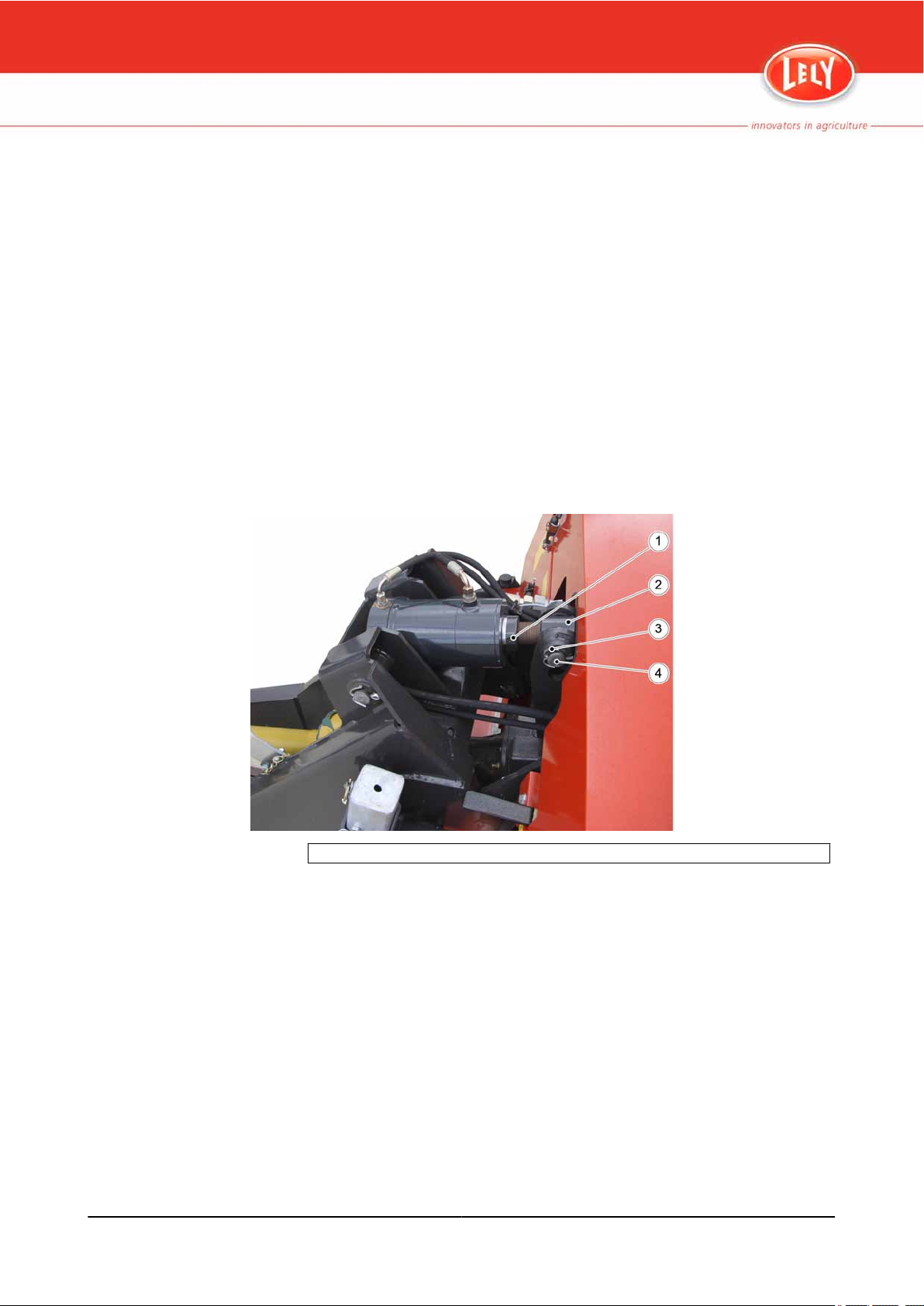
Page 19

L-H007-1104EN
1. Control valve - 2. Rod for control from the position next to the tailgate (position A = conveyor
off, position B = conveyor on) - 3. Hydraulic motor
Figure 11. Hydraulic Motor of the Floor Conveyor
Introduction 1-11
Page 20

1.5.3 Tailgate
The tailgate hangs from the tailgate boom bar with 3 hinges and is locked at
the bottom-left and bottom-right side. The locks can be unlocked with a lever
at the rear left-bottom side of the carriage.
There are also latches at the top-left and top-right side of the tailgate. These
are operated with a lever at the rear side of the tailgate. When locked, the
tailgate can be lifted to a wide open position using the left and right hydraulic
lifting arms. Lifting and lowering is done from the control panel in the tractor
cabin.The locks at the bottom-left and bottom-right side of the tailgate open/
close automatically in this case.
Whether the tailgate must be just unlocked or wide open depends on the
overhead space available at the unloading site. Use wide open whenever
possible.
The button on the wire mesh on the inside of the carriage serves as a sensor
to detect the carriage full status.
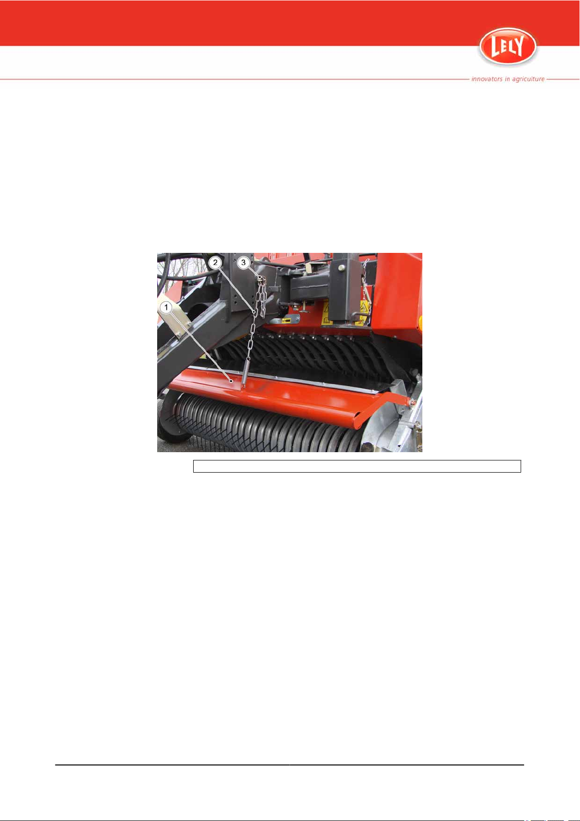
1. Hydraulic lifting arm - 2. Latch - 3. Latch lever (position A = latch locked to enable tailgate
lifting, position B = latch unlocked) - 4. Tailgate - 5. Rear lights and indicators - 6. Lock lever
(push in the direction of the arrow to unlock the tailgate) - 7. Lock - 8. Hydraulic ram for
automatic unlocking
Figure 12. Tailgate
L-H007-1104EN
1-12 Introduction
Page 21

L-H007-1104EN
Figure 13. Tailgate Just Open (left) and Wide Open (right)
Introduction 1-13
Page 22

1.5.4 Under-carriage
In case of a single wheel axle, the axle is fixed to the under-carriage without
springs. For the tandem axle version, both wheel axles are suspended from
packages of leaf springs. The wheels are fixed (i.e. not steered). Various tyre
types are available.
All wheels are provided with a brake that can be activated:
mechanically by the parking brake
•
and
• mechanically by an (optional) overrun mechanism that is activated when
the tractor slows down or when riding downwards from a slope (however,
a freewheel mechanism in the wheels allows reverse driving)
or
• hydraulically by a hydraulic brake signal provided by the tractor
or
• pneumatically by a pneumatic brake signal and pneumatic power
(compressed air) provided by the tractor
In the case of a pneumatic brake ram, the brake force can be adapted to the
load in the carriage. This can be done either:
• manually via a lever (4 settings)
or
• automatically (Automatic Load-sensitive Brake system, ALB). For this
system, the lever that controls the brake force valve is connected to the leaf
spring package. The further the leaf springs deflect, thus the more load, the
higher the brake force.
If there are two wheel axles and hydraulic or pneumatic brake rams, the parking
brake is only connected to the front wheel brakes.
Optionally, mudguards can be mounted above the wheels.
1. Leaf spring suspension (only for tandem axle version) - 2. Brake ram - 3. Brake cam shaft
- 4. Parking brake connection
L-H007-1104EN
Figure 14. A Brake Configuration
1-14 Introduction
Page 23

L-H007-1104EN
Left: version for manual setting (position A = air brake disabled, position B = carriage empty,
position C = carriage half full, position D = carriage full) - Right: ALB version
Figure 15. Pneumatic Break Force Valve
Introduction 1-15
Page 24

1.6 Hydraulic System
The hydraulic system can be used in combination with three different types of
tractor hydraulic systems:
conventional fixed displacement pump (the pump runs continuously and a
•
valve recycles the over-pressure)
• load sensing system (the pump capacity is controlled to deliver pressure
and flow on demand)
• closed centre system (the pump runs continuously but there is no recycle
flow if no valve is operated)
Most of the control valves are either:
• in a control panel in the tractor cabin (manually controlled valves)
or
• electrically controlled by an electric control panel in the tractor cabin
(Comfort system). In this case, the control valves are mounted under a
cover at the front-right side of the carriage.
1. Pin latch to hold the cover open - 2. Cover - 3. Label with valve assignments - 4. Hole in
cover (push a screwdriver through the hole to unlock the cover) - 5. Hydraulic hoses from/to
tractor - 6. Control panel connection - 7. Filter - 8. Valve block with control valves
Figure 16. Hydraulic Control Valves (Comfort System)
L-H007-1104EN
1-16 Introduction
Page 25

1.7 Drive System
The pick-up unit and the cutting unit are driven by the PTO connection of the
tractor. The transmission is as follows:
L-H007-1104EN
1. The
2. The PTO shaft drives the (angular) gear box via an overload protection.
3. The gear box is connected to the dog clutch that allows to engage/
4. The lateral shaft drives the rotor of the cutting unit via 3 gearwheels.
5. The middle gearwheel drives the pick-up unit via:
6. The pick-up unit shaft with the sprocket wheel drives the rotor with the
PTO of the tractor drives the telescopic PTO shaft of the Tigo. This
PTO shaft can be either:
• wide angle (max. 70°) at the tractor side and normal angle (max. 35°)
at the Tigo side
or
• wide angle at both sides (recommended in case of a movable
hydraulic drawbar)
disengage the lateral shaft. The lever for manual operation of the clutch
is at the front side of the Tigo. If the pick-up unit is lifted, an override
mechanism disengages the clutch, independent of the clutch lever
position.
• a sprocket wheel/chain transmission to a double sprocket wheel on
a mount on the main frame
• a sprocket wheel/chain transmission from the double sprocket wheel
to the sprocket wheel on the shaft of the pick-up unit
This configuration of two sprocket wheel/chain transmissions allows
the pick-up unit to be lifted/lowered.
tines via a freewheel clutch.
The overload protection on the PTO shaft is dedicated to the Tigo and prevents
damage to the cutting unit when it is jammed by a foreign object. If the shaft
torque exceeds 1400 Nm, the overload protection cuts off the transmission.
The overload protection can be reset by disengaging the dog clutch at low
rotational PTO speed (remove the blockage before engaging the clutch again).
The freewheel clutch of the pick-up unit allows the tines to rotate freely and,
therefore, protects the tines when the pick-up unit is not driven and the tines
touch objects on the ground during reverse driving.
Note:
Introduction 1-17
For details of the PTO shaft, see the manual of the PTO shaft.
Page 26

1. Safety cover of the overload protection - 2. Cover above the cutting unit (to open, release
the rubber hand grip at the front and use the strut in the lower right corner to hold the cover
open) - 3. Dog clutch lever (position A = clutch engaged, position B with lock = clutch
disengaged)
Figure 17. Dog Clutch Lever
1. End of lateral shaft (can be turned manually using the Lely Tigo Tool) - 2. Sprocket wheel
- 3. Chain - 4. Chain tensioner - 5. Lely Tigo Tool (stowed away) - 6. Mechanism to override
the dog clutch lever when the pick-up unit is lifted
L-H007-1104EN
Figure 18. External Parts of the Drive System
1-18 Introduction
Page 27

1.8 Control Panel
Most functions can be operated from a control panel that can be installed in
the tractor cabin. The control panel can be either hydraulic or electric.
1.8.1 Hydraulic Control Panel
The hydraulic control panel is connected to the tractor and the Tigo with
hydraulic hoses and has a mount that allows to install/uninstall the panel by
hand. The valves in the hydraulic control panel are to select a device, not to
extend/retract the corresponding ram. This is done via a control valve of the
tractor.
Lever 1: To lift and lower the pick-up unit
Set the lever to "Open" (the other levers should be set to "Closed").
1.
2. Lift/lower the pick-up unit using the general control valve of the tractor.
3. Set the lever back to "Closed".
Note:
WARNING
CAUTION
L-H007-1104EN
Note:
Leave the lever in the position "Open" and the general control valve in
the position for lowering during fodder crop loading.
Lever 2: To lift and lower the tailgate
Make sure that no persons are behind the tailgate.
Make sure that the tailgate latches are locked.
1. Set the lever to "Open" (the other levers should be set to "Closed").
2. Lift/lower the tailgate lifting arm using the general control valve of the
tractor.
3. Set the lever back to "Closed".
The tailgate will be unlocked/locked automatically.
Lever 3: To lift and lower the drawbar (if a hydraulic drawbar is present)
1. Set the lever to "Open" (the other levers should be set to "Closed").
2. Lift/lower the drawbar using the general control valve of the tractor.
3. Set the lever back to "Closed".
Lever 4: To fold the open superstructure up and down (if an open
superstructure with hydraulic ram is present)
1. Set the lever to "Open" (the other levers should be set to "Closed").
2. Fold up/down the open superstructure using the general control valve
of the tractor.
3. Set the lever back to "Closed".
To move the floor conveyor:
Introduction 1-19
Page 28

• The
hydraulic motor of the floor conveyor is directly connected to a second
general control valve of the tractor, so there is no lever to select it. The
control valve located near the hydraulic motor should be open to allow
control from the tractor cabin. The speed varies with the speed of the tractor
engine.
1. Select rams to lift/lower the pick-up unit - 2. Select rams to lift/lower the tailgate - 3. Select
ram to move the drawbar (optional) - 4. Select ram to fold the open superstructure (optional)
- 5. Panel mount - position A = closed, position B = open (select)
Figure 19. Hydraulic Control Panel
L-H007-1104EN
1-20 Introduction
Page 29

1.8.2 Comfort System
The Comfort system provides an electric control panel that is connected to the
Tigo with a cable and a connector and has a mount that allows to install/
uninstall the panel by hand.
S1: To lift and lower the pick-up unit
Hold in top position to lift the pick-up unit.
1.
2. Set to bottom position to lower the pick-up unit and to keep it low during
fodder loading.
3. Set to centre position to stop lifting/lowering, possibly leaving the pickup in an intermediate position.
S2: To lift and lower the drawbar (if a hydraulic drawbar is present)
1. Hold in top position to lift the drawbar.
2. Hold in bottom position to lower the drawbar.
3. Release to centre position to stop lifting/lowering the drawbar or when
the drawbar is at the upper/lower position.
S3: To move the knife assembly in and out (if hydraulic rams are present)
1. Hold in top position to move the knives in (the number of knives that
move in should be set in advance using the Lely Tigo Tool).
2. Hold in bottom position to move the knives out.
3. Release to centre position to stop moving out/in or when the knives are
fully out or in.
L-H007-1104EN
Note:
WARNING
CAUTION
Note:
S4: To move the floor conveyor
1. Make sure that the control valve located at the hydraulic motor is open
to allow control from the tractor cabin.
2. Set to bottom position to move the floor conveyor.
3. Set to centre position to stop the floor conveyor.
The top position has no function.
S5: To lift and lower the tailgate
Make sure that no persons are behind the tailgate.
Make sure that the tailgate latches are locked.
1. Hold in top position to lift the tailgate.
2. Hold in bottom position to lower the tailgate.
3. Release to centre position to stop lifting/lowering the tailgate or when
the tailgate is at the wide open/closed position.
The tailgate will be unlocked/locked automatically.
S6: To fold the open superstructure up and down (if an open superstructure
with hydraulic ram is present)
• Hold in top position to fold up the open superstructure.
Introduction 1-21
Page 30

• Hold in bottom position to fold down the open superstructure (only if the
carriage is empty).
• Release
to centre position to stop folding the open superstructure up/down
or when the open superstructure is fully folded up/down.
H1: Buzzer (optional)
• Sounds when both the floor conveyor is activated and the carriage is full
(sensor on the tailgate activated). Releasing switch S4 will end the sound.
S1 Lift/lower the pick-up unit - S2 Lift/lower the drawbar (optional) - S3 Move the knives in/out
(optional) - S4 Move the floor conveyor - S5 Lift/lower the tailgate - S6 Fold the open
superstructure up/down (optional) - H1 Buzzer for carriage full alert (optional) - H Plug to
connect the control panel to the Tigo - Bottom: control panel in mount
Figure 20. Electric Control Panel (Comfort System)
L-H007-1104EN
1-22 Introduction
Page 31

1.9 Optional Extras
1.9.1 Lely Grinder
The Lely grinder quickly and correctly sharpens the knives of the Lely Tigo. A
blunt
is moved at the correct angle across the blade of the knife.
knife is installed in a supporting frame. To sharpen the knife, the grinder
L-H007-1104EN
Figure 21. Lely Grinder
Introduction 1-23
Page 32

L-H007-1104EN
1-24 Introduction
Page 33

2.1 Signal Words
2. SAFETY
This chapter contains safety instructions you must obey when you use or do
maintenance on your Lely Tigo. It also explains the safety decals on the Lely
Tigo.
Note the use of the signal words DANGER, WARNING and CAUTION. The
signal word for each message uses the following guidelines:
DANGER
WARNING
CAUTION
Note:
2.2 Safety Instructions
L-H007-1104EN
Danger: Indicates an imminently hazardous situation that, if
not avoided, will result in death or serious injury.
Warning: Indicates a potentially hazardous situation that, if not avoided,
could result in death, serious injury or product damage, and includes
hazards that are exposed when guards are removed.
Caution: Indicates a potentially hazardous situation that, if not avoided, may
result in minor or moderate injury or damage to the product or property.
Note: This shows extra information that may help the reader.
General safety instructions:
• Read this manual completely before operating the Tigo. If anything is not
clear, please contact your local dealer.
• Use the Tigo only for the purpose for which it was designed.
• Follow all safety regulations, including those in this manual and instructions
or warnings indicated on the machine.
• Always be alert on hazards and unusual signs (such as leakage and noise).
Observe all safety precautions.
• Let the Tigo be operated, driven and maintained by authorised persons
only.
• Use protective clothing, gloves, safety glasses and ear protectors, if
necessary.
• Keep people and objects away from moving parts.
• Always use a tractor with a cab.
• Clean the safety decals regularly so that they can be read at all times.
Replace the safety decals if necessary.
Safety instructions for preparing operation:
• Always connect the Tigo to the tractor as described in this manual. Only
connect the Tigo to a tractor trailer hitch that complies with your local
regulations.
Safety 2-1
Page 34

• Make sure the front axle weight of the tractor is sufficient and that you do
not exceed the rear axle weight.
• Never
connect the Tigo to the tractor when the tractor engine is still running.
• Depressurize the hydraulic system before you connect hydraulic hoses.
• If the Tigo has a hydraulic or pneumatic brake, connect the brake hose(s)
to the tractor.
• Make sure all safety guards and protection devices are installed and
function correctly.
• Always test the brakes before operation. Never drive the Tigo with damaged
brakes.
• Make sure all the lights on the Tigo operate correctly. Make sure the lights
are not covered by dirt.
• Before traveling:
• make sure the (hydraulic) drawbar is in the transport position
• make sure the parking jack is lifted and locked
• make sure the pick-up unit is lifted
• make sure the tailgate is closed and locked
• make sure that all other movable parts (such as the foldable
superstructure and covers) are locked
Safety instructions for driving on public roads:
• Always obey your local road traffic regulations.
• Use flashing lights or other safety signs, when necessary.
• Be alert on the maximum height when approaching bridges, tunnels,
electrical lines etc.
• Do not allow passengers unless there is an extra seat in the tractor. Persons
shall never be transported in or on the Tigo.
• Do not operate the hydraulics when driving on the public road.
Safety instructions for operation:
• Operate the Tigo in a safe manner.
• Make sure no people are in the danger zone when the Tigo is in operation.
This is especially important when you work near or on areas that are
accessible to the public.
• Make sure there are no objects in the field that could be thrown up by the
Tigo.
• Do not stand in or on the Tigo.
• Do not make sudden curves when driving uphill or downhill.
• Always reduce your driving speed when driving downhill.
• Do not disconnect the clutch or change gears on a slope.
• Do not exceed the maximum load or maximum axle loads.
Safety instructions for ending operation:
L-H007-1104EN
• Depressurize the hydraulic system before you disconnect hydraulic hoses.
• Always park the Tigo on a flat stable ground.
2-2 Safety
Page 35

• Before disconnecting the Tigo from the tractor:
make sure the parking jack is on the ground
•
• make sure the parking brake is engaged
• make sure the wheel wedges are placed
Safety instructions for maintenance and troubleshooting:
• Stop the tractor engine, the Power Take-Off (PTO) and all moving parts
before doing maintenance or troubleshooting. Never reach into moving
parts or parts that may come life.
• Install the wheel wedges to prevent the Tigo from moving before doing
maintenance.
• Make sure the covers are well locked if they are open.
• Obey the maintenance schema in this manual.
• Do not modify the Tigo.
• Only use genuine Lely parts.
2.3 Explanation of the Safety Decals
L-H007-1104EN
Read the manual and the safety instructions before operating the
machine.
Stay away from the tailgate as long as the tractor may drive
backwards or the tailgate may be operated.
Keep hands away from (external) machine parts as long as they
may come live.
Safety 2-3
Page 36

Keep hands away from internal machine parts as long as the
machine is not completely stationary or may come live.
Do not step on the floor conveyor as long as its hydraulic motor is
moving or may come live.
Stop the tractor engine and remove the key from the tractor ignition
lock before doing troubleshooting or maintenance.
L-H007-1104EN
Release the pressure of the hydraulic and/or pneumatic system
before doing troubleshooting or maintenance.
Stay away from the pick-up unit as long as the PTO shaft is
connected and the tractor engine is running.
2-4 Safety
Page 37

L-H007-1104EN
Regularly check the wheel nuts for tight
fit.
Do not exceed the maximum PTO speed of 540 rpm.
Do not exceed the maximum driving speed of 25 km/h.
Safety 2-5
Page 38

L-H007-1104EN
2-6 Safety
Page 39

3. FIRST USE
3.1 Finish the Superstructure
L-H007-1104EN
1. Hook
2. Fasten the rear tarpaulin between the bow and the tailgate boom using
3. Fasten the (optional) front-top tarpaulin to the front wall using the
the top rigging ropes between the hooks on the front wall and the
hooks on the bow, thereby leading the ropes through the lugs on the
middle crossbar (if applicable). In case of the open superstructure, also
attach the side rigging ropes by looping them through the lugs on the
bow corners and hooking the springs at the ends of the ropes to the lugs
on the front wall corners.
the mounting rod at the bow side. Secure the mounting rod with a linch
clip at both sides.
mounting rod. Secure the mounting rod with a linch clip at both sides.
Tighten the other side of the tarpaulin to the lugs on the side walls using
the expander ropes (one at each side).
1. Mounting rod - 2. Optional front-top tarpaulin - 3. Expander rope - 4. Bow - 5. Mounting rod
for rear tarpaulin - 6. Side rigging rope - 7. Top rigging rope - 8. Front wall
Figure 22. Finish the Open Superstructure
First Use 3-1
Page 40

3.2 Adjust the Length of the PTO Shaft
CAUTION
The first time you connect the Tigo to each tractor, refer to the instructions
supplied with the PTO shaft and make sure the minimum and maximum
overlap of the two parts of the PTO shaft is correct.
Disconnect the two halves of the telescopic PTO shaft.
1.
2. Hold the two PTO shaft halves next to each other in the shortest
operating position.
3. Mark the shortest operating position on the outer safety guard tube.
4. Substract 40 mm from the first mark and mark it with a second mark.
5. Remove the safety guard tubes from the PTO shaft halves.
6. Shorten the outer safety guard tube of the PTO shaft at the second mark.
7. Shorten the inner safety guard tube by the same distance.
8. Shorten the inner and outer PTO shaft halves by the same distance.
9. Deburr and clean the safety guard tubes and the PTO shaft halves.
10. Install the safety guard tubes on the PTO shaft halves.
11. Connect the two PTO shaft halves.
Figure 23. Shorten the Inner Safety Guard Tube and the PTO-shaft halves
Figure 24. Mark the Outer Safety Guard Tube of the PTO shaft
L-H007-1104EN
3-2 First Use
Page 41

3.3 Install the PTO Shaft with the Overload Protection
1. Clean and grease the profile of the main drive shaft of the Tigo.
Loosen and turn out the clamping cone of the overload protection.
2.
3. Open the maintenance hole in the guard cone. Slide the overload
protection (with the connected PTO shaft) onto the drive shaft so that
the location hole points towards the maintenance hole.
4. Position the location hole for the clamping cone above the ring groove
of the shaft.
5. Turn the clamping cone into the location hole and tighten firmly
(approximately 70 Nm) while moving the hub slightly to and fro in
longitudinal direction.
6. Check if the seat of hub of the overload protection is tight and firm by
compression and tensioning movements.
7. Close the maintenance hole in the guard cone.
L-H007-1104EN
1. Clamping cone - 2. Location hole - 3. Ring groove of the main drive shaft
Figure 25. Install the PTO Shaft with the Overload Protection
First Use 3-3
Page 42

3.4 Adjust the Height of the Drawbar
The height of the drawbar should be adjusted so that, when the Tigo is
connected to the tractor in travelling position, the upper edge of the front
crossbeam
is important for the optimal performance of the pick-up unit. The way to adjust
the height depends on the type of drawbar. In both cases the tractor and the
Tigo should be on a flat ground, with the Tigo connected to the tractor and the
parking jack slightly above the ground.
of the main frame is approximately 118 cm above the ground. This
Figure 26. Optimal Drawbar Height
L-H007-1104EN
3-4 First Use
Page 43

3.4.1 Drawbar with Spindle
Note:
Note that the threads at the left and the right side of the spindle are
opposite.
Release both counter nuts of the spindle.
1.
2. Adjust the spindle as necessary.
3. Tighten both counter nuts.
L-H007-1104EN
1. Spindle - 2. Counter nuts
Figure 27. Adjust the Height of a Drawbar with a Spindle
First Use 3-5
Page 44
3.4.2 Drawbar with Hydraulic Ram
1. Release the pressure of the hydraulic ram.
Remove the split pin of the pin of the piston rod end eye. Do not yet
2.
remove the pin.
3. Loosen the hexagon locking bolt of the piston rod.
4. Lower the parking jack until it rests on the ground.
5. Remove the pin of the eye of the piston rod end.
6. Screw the piston rod end in or out as necessary.
7. Re-insert the pin through the eye of the piston rod end.
8. Lift the parking jack slightly above the ground by turning its crank.
9. Verify if the drawbar height is correct. If this is not the case, repeat the
steps 4 - 9.
10. Tighten the hexagon locking bolt of the piston rod.
11. Re-install the split pin to secure the pin of the piston rod end eye.
1. Hexagon locking bolt - 2. Piston rod end - 3. Split pin - 4. Pin
Figure 28. Adjust the Height of a Drawbar with Hydraulic Ram
L-H007-1104EN
3-6 First Use
Page 45

3.5 Adapt the Electric Power Connection
In case of the Comfort system, the electric cable to be connected to the tractor
does not only transfer the light signals, but also the electric power for the
hydraulic control valve system. For this, the tractor shall provide continuous
power on the 54g terminal (+) and the 31 terminal (-) of the 7-pole socket on
the tractor side. It is best to have these terminals wired directly to the tractor
battery with 2.5 mm2 wire and a fuse of 16 A for the anode (+).
Figure 29. Direct Continuous Power Wire for the Comfort System
L-H007-1104EN
First Use 3-7
Page 46

3.6 Connect the Electric Cables
1. Connect
the cable of the lighting system to the 7 pole socket at the right
front of the Tigo.
2. If the Tigo has a Comfort System, connect the cable of the control panel
to the socket near the hydraulic valves under the cover at the front right
side.
1. Socket for lighting system cable (including power for the Comfort system) - 2. Socket for
control panel (Comfort system)
Figure 30. Connect the Electric Cables
L-H007-1104EN
3-8 First Use
Page 47

3.7 Adjust the Load Sense Adjustment Screw
In case of the Comfort system, there is a Load Sense adjustment screw that
needs adjustment depending on the hydraulic system of the tractor.
CAUTION
L-H007-1104EN
Only make adjustments when there is no pressure on the hydraulic system
(preferably switch off the tractor).
for a conventional fixed displacement pump system: screw out to the end
•
point
• for a load sensing system: screw in to the end point
• for a closed centre system: screw in to the end point
Figure 31. Adjust the Load Sense Adjustment Screw
First Use 3-9
Page 48

3.8 Examine the Lever Setting of the ALB
If the Tigo has an Automatic Load-sensitive Brake system:
Make sure that the length of the lever of the automatic load responsive
•
regulating valve is the same as the length described on the Wabco or
Haldex performance label.
Figure 32. Examine the Lever Setting of the ALB Valve
L-H007-1104EN
3-10 First Use
Page 49

4.1 At First
4. BEFORE OPERATION
When the Tigo is not connected to the tractor, it shall rest on its parking jack,
the parking brake shall be engaged and the wheel wedges shall be placed.
maintenance (greasing, replacement of lubricating oil, cleaning of filters
• All
etc.) should have been done according to the maintenance schema. The
knives of the cutting unit should be sharp and well adjusted.
• Make sure that the tyres are at the right air pressure (page 9-7).
• Make sure that the wheel nuts are tight (page 9-6).
• Make sure that all safety covers are in a good condition and closed.
• Make sure that all hoses and cables are in good condition.
• Make sure that hinged assembly parts (tailgate, foldaway open
superstructure, covers etc.) are locked.
L-H007-1104EN
Before Operation 4-1
Page 50

4.2 Connect the Cables and Hoses to the Tractor
WARNING
WARNING
Make sure there are no persons near the Tigo when you connect it to the
tractor.
When connecting hydraulic hoses, take care not to swap the pressure
side and the return side by mistake.
Reverse the tractor to the drawbar and make sure the tractor and the
1.
Tigo are aligned.
2. If the Tigo does not have a Comfort system:
• Connect the red-marked hydraulic hose of the hydraulic control panel
to a single acting control port of the tractor.
• Connect the red-marked hydraulic hose of the hydraulic motor of the
floor conveyor to another single acting control port of the tractor.
• Connect the blue-marked common return hydraulic hose to a
pressure-free return port of the tractor.
3. If the Tigo has a Comfort system:
• Connect the red-marked hydraulic hose to a single acting control port
of the tractor.
• Connect the blue-marked hydraulic hose to a pressure-free return
port of the tractor.
4. If the Tigo has a load sensing hose:
• Connect the red-marked hydraulic hose to a hydraulic power outlet
of the tractor.
• Connect the red-marked load sensing hose (hose with smallest
diameter) to the load sensing port of the tractor.
• Connect the blue-marked hydraulic hose to a pressure-free return
port of the tractor.
5. If the Tigo has a hydraulic brake system:
1. Connect the hydraulic brake hose to the tractor trailer brake
socket.
2. Make sure that the brakes operate correctly.
6. If the Tigo has a pneumatic brake system:
1. Make sure that the sealing rings in the brake coupling heads are
clean and in good condition.
2. Connect the red-marked air hose to a red marked air socket on
the tractor.
3. Connect the yellow-marked hose to a yellow marked air socket
on the tractor.
4. Make sure that the brakes operate correctly and that there is no
air leaking through the coupling head seals.
7. Connect the plug of the electric cable to the 7-pole socket of the tractor.
8. Make sure all the lights on the Tigo operate correctly.
L-H007-1104EN
4-2 Before Operation
Page 51

9. Install
the control panel (either hydraulic or electric) on the mount in the
tractor cabin.
1. Red-marked hydraulic hose - 2. Blue-marked hydraulic hose - 3. Red-marked load sensing
hose - 4. Red-marked air hose - 5. Yellow-marked air hose - 6. Red-marked hydraulic brake
system hose
Figure 33. Hydraulic and Pneumatic Hoses
L-H007-1104EN
Before Operation 4-3
Page 52

4.3 Connect the Tigo to the Tractor
WARNING
WARNING
CAUTION
Make sure there are no persons near the Tigo when you connect it to the
tractor.
Always switch off the tractor engine and remove the ignition key before
you leave the tractor cab.
Do not move the Tigo with the parking jack in its lowest position.
1.
Make sure that the tractor coupling system is aligned with the drawbar
of the Tigo. Align the drawbar in height by turning the crank of the parking
jack.
2. Connect the Tigo to the tractor:
1. Bring the drawbar coupling eye into the coupling fork of the
tractor.
2. Install the pin.
3. Secure the pin with the pin lock.
3. If the Tigo has a parking brake lever with a nylon break-away rope,
attach the rope end to the tractor.
4. Retract the parking jack:
1. Turn the crank of the parking jack clockwise to release the parking
jack foot from the ground. Turn until the telescopic part of the
stand is fully upwards (otherwise, the pin can not be inserted in
step 4).
2. Remove the pin that locks the stand.
3. Lift the telescopic part of the stand by the hand grip on the foot
plate.
4. Re-install the pin.
5. Pull down the hinge locking pin and swivel the hinge towards the
front crossbar.
6. Release the hinge locking pin.
L-H007-1104EN
5. If the Tigo has a hydraulic drawbar, lower the drawbar to the transport
position.
WARNING
4-4 Before Operation
Make sure the tractor PTO is disengaged before you connect the PTO
shaft to the tractor PTO.
6. Connect the PTO shaft to the tractor PTO.
7. Secure the PTO guard against rotating by fixing its chain to a rigid part
of the tractor.
8. Remove the wheel wedges and store them in the mounts under the
carriage, behind the (rear) wheels.
9. Disengage the parking brake by pulling the lever a bit forward, then fully
backward.
Page 53

L-H007-1104EN
1. Crank - 2. Pin - 3. Hinge - 4. Hinge locking pin - 5. Stand - 6. Telescopic bottom part of the
stand with foot plate
Figure 34. Move the Parking Jack to the Top Position
Figure 35. Connect to the Tractor
Before Operation 4-5
Page 54

4.4 Adjust the Working Depth of the Pick-up
The pick-up tines should be slightly above the ground during loading fodder
crop. They should never scratch along the ground. Stony ground requires a
higher setting. Adjust the working depth as follows:
Lift the pick-up unit.
1.
2. On both sides of the pick-up:
1. Remove the linch clip from the slotted bar.
2. Adjust the guide wheel to the applicable position and re-install the
linch clip into the corresponding slot of the slotted bar.
3. Make sure that the position of the guide wheels is the same at both sides.
4. Lower the pick-up unit to the ground and make sure that the working
depth is correct.
1. Linch clip - 2. Slotted bar
Figure 36. Adjust the Working Depth of the Pick-up Unit
L-H007-1104EN
4-6 Before Operation
Page 55
4.5 Adjust the Height of the Wind Guard
The optimal height of the wind guard depends on the type of fodder crop. Fine
fodder crop requires a somewhat lower setting than coarse fodder crop. As a
starting
Set the wind guard height as follows:
1. Remove the linch clip from the lug on the drawbar from which the wind
2. Suspend the wind guard chain from the lug at the appropriate link.
3. Re-install the linch clip.
point, adjust the height so that the wind guard just touches the swath.
guard chain is suspended.
L-H007-1104EN
1. Wind Guard - 2. Chain - 3. Lug with linch clip
Figure 37. Adjust the Height of the Wind Guard
Before Operation 4-7
Page 56

4.6 Fold Up the Open Superstructure
In case of an open superstructure without a hydraulic ram:
Take the rocker lever that is stowed on the axle support cross beam.
1.
2. Install the rocker lever by sticking its fork on the stud on the rung, then
swiveling the rocker lever on the pin. Secure the rocker lever using the
linch clip.
3. Remove the R-clip from the pin that holds the brace arm.
4. Release the brace arm by pulling its hand grip.
5. Pull the rocker lever downwards to fold up the superstructure.
6. Re-install the brace arm on the pin and secure it with the R-clip.
7. Remove the linch clip that secures the rocker lever and remove the
rocker lever from the pin and the stud.
8. Stow the rocker lever on the axle support cross beam.
Folding down is done in the same way, but then pushing the rocker lever
upwards in step 5.
In case of an open superstructure with a hydraulic ram, just operate the ram.
CAUTION
Always mind the available overhead space when driving through doors,
tunnels etc.
L-H007-1104EN
4-8 Before Operation
Page 57

L-H007-1104EN
1. Rocker lever - 2. Stud - 3. Pin for rocker lever - 4. Linch clip - 5. Brace arm - 6. Pin for brace
arm - 7. R-clip
Figure 38. Fold the Open Superstructure - Mount Rocker Lever, Release Brace
Arm and Fold
Before Operation 4-9
Page 58

Figure 39. Fold the Open Superstructure - Secure Brace Arm and Remove
Rocker Lever
L-H007-1104EN
4-10 Before Operation
Page 59

4.7 Select the Number of Knives
Using the Lely Tigo Tool, select the appropriate number of knives by moving
movable upper sub-group and/or the (optional) lower knife group in or out.
the
Note:
L-H007-1104EN
The (optional) lower knife group does not have a sub-group dat can be
moved in or out. It is only possible to move the whole lower knife group
in or out.
To move the (sub-)group out:
1. Place the Lely Tigo Tool on the cam of the (sub-)group (right side of the
Tigo).
2. In case of the upper sub-group:
1. Pull the Lely Tigo Tool slightly counterclockwise and hold it to
release the tension from the safety link.
2. Release the safety link from the pin.
3. Pull the Lely Tigo Tool clockwise to move the (sub-)group out.
To move the (sub-)group in:
1. Place the Lely Tigo Tool on the cam of the (sub-)group (right side of the
Tigo).
2. Pull the Lely Tigo Tool counterclockwise to move the (sub-)group in.
3. In case of the upper sub-group:
1. Hold the Lely Tigo Tool pulled counterclockwise.
2. Attach the safety link to the pin.
4. Remove the Lely Tigo Tool.
Before Operation 4-11
Page 60

1. Cam - 2. Safety link - 3. Pin - 4. Knife - 5. Lely Tigo Tool - Upper figure: 17 knives in, lower
figure: 5 knives in
Figure 40. Select the Number of Knives of the Upper Knife Group
L-H007-1104EN
4-12 Before Operation
Page 61

L-H007-1104EN
1. Cam - Position A = in, position B = out
Figure 41. Select the Knives of the (Optional) Lower Knife Group
Before Operation 4-13
Page 62

4.8 Drain the Air Container
If the Tigo has a pneumatic brake:
Use a wire to pull the pin of the drain valve to drain the water from the air
•
container of the brake system (located under the carriage, behind the (rear)
wheel). If the drainage valve is clogged, screw it out, clean it and screw it
in again.
WARNING
Make sure the pressure of the pneumatic brake system is not less than
5 bar before you start driving (read the pressure gauge of the tractor
pneumatic system).
Figure 42. Drain the Water From the Air Container of the Brake System
L-H007-1104EN
4-14 Before Operation
Page 63

5. OPERATION
5.1 Load the Fodder Crop
WARNING
WARNING
CAUTION
WARNING
WARNING
WARNING
WARNING
L-H007-1104EN
Make sure no persons are near the Tigo when you engage the PTO.
Make sure no persons are within a 25 meter radius of the Tigo during
operation.
Do not exceed the maximum PTO speed of 540 rpm.
Always switch off the tractor engine before you leave the tractor cab.
Do not operate the Tigo without safety guards or covers, or if the safety
guards or covers are damaged.
Always operate the Tigo with the safety guards or covers down and
engaged in the clamping blocks.
Always keep the tailgate closed when you drive on public roads.
1.
Position the tractor at the beginning of the swath.
2. Carefully engage the PTO at the lowest possible engine speed.
3. Slowly increase the speed of the PTO to the maximum of 540 rpm.
4. Lower the pick-up unit to the ground.
5. Drive the tractor over the swath. The pick-up performance is best at
higher speeds.
6. Before making a (sharp) turn:
• Lift the pick-up unit.
• Disengage the PTO.
7. Regularly activate the floor conveyor to move the collected fodder crop
to the rear. When the (optional) buzzer sounds upon activating the floor
conveyor, the Tigo is full. In that case stop loading:
1. Lift the pick-up to the top position.
2. Disengage the PTO.
3. Return to the unloading site.
Operation 5-1
Page 64

5.2 Remove a Blockage by Moving the Knives Out and In
WARNING
Never reach into the pick-up unit, the cutting unit or the conveyor
channel, when the tractor engine is still running.
Disengage the PTO.
1.
2. Move the knives out:
• If the cutting unit has no hydraulic rams for moving the knives in and
out:
1. Place the Lely Tigo Tool on the cam of the turnbuckle.
2. Push the Lely Tigo Tool clockwise and remove the locking plate
that locks the turnbuckle fork.
3. Pull the Lely Tigo Tool counterclockwise.
• If the cutting unit has hydraulic rams for moving the knives in and out:
use the control panel.
3. Engage the PTO at the lowest possible speed.
4. If the overload protection is reset (so that the Tigo is driven again), move
the knives in:
• If the cutting unit has no hydraulic rams for moving the knives in and
out:
1. Pull the Lely Tigo Tool on the cam of the turnbuckle clockwise.
2. Lock the turnbuckle fork with the locking plate.
3. Remove the Lely Tigo Tool from the cam.
• If the cutting unit has hydraulic rams for moving the knives in and out:
use the control panel.
L-H007-1104EN
WARNING
5. If the blockage has been resolved, the procedure ends here. Otherwise,
proceed with the next steps.
6. Disengage the PTO.
7. Move the knives out (see step 2).
8. Stop the tractor engine.
9. Disengage the dog clutch.
10. Rotate the gear in reverse using the Lely Tigo Tool as a crank on the
end of the lateral shaft.
11. Remove the blocking object(s).
Remove the Lely Tigo Tool from the lateral shaft before engaging the dog
clutch.
12. Engage in the dog clutch.
13. Start the tractor engine.
14. Engage the PTO.
15. Move the knives in (see step 4).
5-2 Operation
Page 65

L-H007-1104EN
Figure 43. Rotate the Gear Manually
Operation 5-3
Page 66

1. Lely Tigo Tool (installed on the cam of the turnbuckle) - 2. Lip to be locked by the locking
plate - 3. Locking plate on turnbuckle fork
Figure 44. Move All Knives Out (Top) and In (Bottom)
L-H007-1104EN
5-4 Operation
Page 67

5.3 Unload the Tigo
WARNING
WARNING
WARNING
Make sure that no persons are behind the tailgate.
Make sure no persons are in the carriage when the floor conveyor is
activated.
Make sure no persons are near the Tigo when the hydraulic drawbar is
raised or lowered.
1.
Position the rear of the Tigo to the appropriate location.
2. If the overhead space allows lifting of the tailgate:
1. Make sure that the tailgate is locked in the tailgate latches.
2. Lift the tailgate.
3. If the overhead space does not allow lifting of the tailgate:
1. Unlock the tailgate latches.
2. Unlock the tailgate.
4. If the Tigo has a hydraulic drawbar and will be unloaded on a silage
clamp:
• Tilt the Tigo by lowering the drawbar. The increased clearance
between the pick-up unit and the ground decreases the risk of
damaging the pick-up unit.
L-H007-1104EN
5. Activate the floor conveyor (either from the tractor cabin or from the
control valve next to the tailgate).
6. If the Tigo is empty, stop the floor conveyor.
7. If the Tigo was tilted, bring the drawbar back to the transport position.
8. If the tailgate was lifted, lower the lifting arms until the tailgate is locked.
9. If the tailgate was not lifted:
1. Drive the Tigo to a place where the overhead space allows lifting
of the tailgate.
2. Lift the tailgate.
3. Lower the lifting arms until the tailgate is locked.
Figure 45. Tilt the Tigo by Lowering the (Optional) Hydraulic Drawbar
Operation 5-5
Page 68

L-H007-1104EN
5-6 Operation
Page 69

6. AFTER OPERATION
6.1 Disconnect the Tigo from the Tractor
WARNING
WARNING
WARNING
WARNING
WARNING
L-H007-1104EN
Unload the Tigo before you disconnect it from the tractor.
Always position the tractor on solid ground before you disconnect the
Tigo from the tractor.
Make sure there are no persons near the Tigo when you disconnect it
from the tractor.
Always switch off the tractor engine before you leave the tractor cab.
Always engage the parking brake and install wheel wedges before you
disconnect the Tigo from the tractor.
1.
Lower the parking jack:
1. Pull down the hinge locking pin and swivel the parking jack
forward.
2. Remove the pin that locks the stand (hold the telescopic part of
the stand by the hand grip on the foot plate).
3. Lower the telescopic part of the stand.
4. Re-install the pin of the stand.
5. Turn the crank of the parking jack counterclockwise until the foot
plate rests on the ground.
WARNING
2. Turn the parking jack crank further until the coupling eye of the drawbar
does not longer rest on the coupling fork of the tractor.
3. If the Tigo has a parking brake lever with a nylon break-away rope,
loosen the rope from the tractor.
4. Engage the parking brake by pulling the lever forward beyond the slack
point.
5. Place the wheel wedges (these are stowed under the carriage, behind
the (rear) wheels).
6. If the Tigo is hydraulically or pneumatically braked from the tractor:
• Disconnect the brake hoses and put the hose ends in the hose
holders on the drawbar.
7. Disconnect the hydraulic hoses from the tractor and put the hose ends
in the hose holders on the drawbar.
8. Unplug the electric cable from the tractor.
9. Unmount the (hydraulic or electric) control panel and remove it from the
tractor cabin.
Make sure the tractor PTO is disengaged before you disconnect the PTO
shaft from the tractor PTO.
10. Loosen the safety chain of the PTO guard at the tractor side.
After Operation 6-1
Page 70

11. Disconnect
the PTO shaft from the tractor PTO. At the side of the Tigo,
the PTO shaft may stay connected with the overload protection on the
main drive shaft.
12. Disconnect the Tigo from the tractor:
1. Remove the pin lock.
2. Remove the pin.
3. Drive the tractor away from the Tigo.
13. Do the 10 hours maintenance.
L-H007-1104EN
6-2 After Operation
Page 71

7. TEST AND ADJUSTMENT
7.1 Remove and Install the Knife Assembly
7.1.1 Remove the Knife Assembly
1. Move the knives out.
Loosen the turnbuckle forks at the left and the right side of the knife
2.
assembly:
1. Remove the R-clip of the pin.
2. Remove the pin.
3. If the cutting unit has hydraulic rams:
1. Remove the washer and linch clip from the stud of the ram.
2. Remove the ram from the stud.
4. Install the (optional) transport wheels:
• Side wheels:
1. Insert the side wheel in the mount.
2. Screw the height adjustment screw out until the wheel touches
the ground.
3. Tighten the butterfly nut of the mount.
L-H007-1104EN
• Steerable centre wheel:
1. Stick the wheel mount onto the crossbar of the knife assembly (in
the middle of the crossbar).
2. Insert the locking plate.
5. At the left and the right side of the knife assembly, release the safety
struts:
1. Remove the R-clip and the washer.
2. Release the strut from the pin.
3. If no transport wheels are installed: swivel the knife assembly to
the ground.
6. Remove the locking pins at the left and right side of the knife assembly:
1. Remove the linch clip from the locking pin.
2. Turn the flag of the locking pin downwards.
3. Remove the locking pin.
Test and Adjustment 7-1
Page 72

1. Turnbuckle fork - 2. Pin - 3. R-clip - 4. Safety strut - 5. Washer and R-clip - 6. Linch clip -
7. Locking pin of knife assembly
Figure 46. Remove the Knife Assembly - Without the Optional Wheels
1. Locking plate - 2. Centre wheel mount - 3. Side wheel mount with butterfly nut - 4. Height
adjustment screw - 5. Side transport wheel
L-H007-1104EN
Figure 47. Remove the Knife Assembly - With the Optional Wheels
7.1.2 Install the Knife Assembly
1. Bring the knife assembly in place under the rotor.
2.
Install the locking pins at the left and right side of the knife assembly:
1. Insert the locking pin.
2. Rotate the flag of the locking pin horizontal.
3. Secure the locking pin with the linch clip.
3. Install the safety struts at the left and right side of the knife assembly:
1. Install the strut on the pin.
2. Secure the strut with the washer and R-clip.
7-2 Test and Adjustment
Page 73

4. Remove the (optional) transport wheels:
Loosen the butterly nuts of the side wheel mounts, screw in the
1.
height adjustment screws and remove the side wheels.
2. Remove the locking plate of the steerable centre wheel mount
and remove the centre wheel assembly.
5. If the cutting unit has hydraulic rams:
1. Install the hydraulic ram on the stud.
2. Secure the hydraulic ram with the washer and the linch clip.
6. Install the turnbuckle forks at the left and the right side of the knife
assembly:
1. Install the turnbuckle fork.
2. Insert the pin.
3. Secure the pin with the R-clip.
7. Move the knives in.
L-H007-1104EN
Test and Adjustment 7-3
Page 74

7.2 Remove and Install a Single Knife
7.2.1 Remove a Single Knife
1. Move the knives out.
Loosen the turnbuckle forks at the left and the right side of the knife
2.
assembly:
1. Remove the R-clip of the pin.
2. Remove the pin.
3. If the cutting unit has hydraulic rams:
1. Remove the washer and linch clip from the stud of the ram.
2. Remove the ram from the stud.
4. At the left and the right side of the knife assembly, release the safety
struts:
1. Remove the R-clip and the washer.
2. Release the strut from the pin.
3. Swivel the knife assembly to the ground.
5. Remove the selected knives:
1. Push the locking bolt on the buckling spring (just push, do not
remove the locking bolt from the buckling spring).
2. Release the buckling spring from the knife.
3. Swivel the knife forward (towards the rotor).
4. Lift the knife from the knife shaft.
L-H007-1104EN
1. Buckle spring - 2. Knife - 3. Locking bolt
Figure 48. Remove a Single Knife
7.2.2 Install a Single Knife
1. Hold the knife with an inclined attitude above the knife shaft and lower
it onto the shaft.
2.
Swivel the knife backwards so that it locks on the knife shaft.
3. Push the locking bolt on the buckling spring and slide it into the slot of
the knife.
4. Release the locking bolt and make sure that it is locked.
7-4 Test and Adjustment
Page 75

5. Repeat the steps 1 - 4 for the other knifes (if applicable).
Swivel the knife assembly upwards.
6.
7. Install the safety struts at the left and right side of the knife assembly:
1. Install the strut on the pin.
2. Secure the strut with the washer and R-clip.
8. If the cutting unit has hydraulic rams:
1. Install the hydraulic ram on the stud.
2. Secure the hydraulic ram with the washer and the linch clip.
9. Install the turnbuckle forks at the left and the right side of the knife
assembly:
1. Install the turnbuckle fork.
2. Insert the pin.
3. Secure the pin with the R-clip.
10. Move the knives in.
L-H007-1104EN
Test and Adjustment 7-5
Page 76

7.3 Adjust the Clearance Between the Knives and the Rotor
Upper knife group:
Open the cover above the cutting unit.
1.
2. Observe the clearance of all knives by looking from above. The
clearance is the distance between knife tip and the tine bar when the
rotor is in such position that the tine bar is closest to the knife tip. In
principle all knives should have the same clearance. However, due to
wear there may be differences. In that case the knife with the smallest
clearance is critical. The clearance should be approximately 3 mm
(estimated by eye). Proceed this procedure if the clearance must be
adjusted.
At both sides of the knife assembly:
3. Loosen the counter nut on the axle of the turnbuckle fork.
4. Release the turnbuckle fork from the upper hinge point:
1. Remove the R-clip of the pin.
2. Remove the pin.
3. Release the turnbuckle fork axle from the hinge.
5. Adjust the turnbuckle fork axle length:
• Screw the axle in to decrease the clearance.
• Screw the axle out to increase the clearance.
6. Re-install the turnbuckle fork axle on its hinge point. Only insert the pin,
not the R-clip.
7. Observe the clearance again. Repeat the steps 4 - 5 until the clearance
is approximately 3 mm at both sides of the cutting unit.
8. If the clearance is good, secure the pin of the upper hinge point with the
R-clip.
9. Fasten the counter nut on the axle of the turnbuckle fork.
Lower knife group (if present):
1. Move out the upper knife group to have sight on the lower knife group.
2. Observe the clearance of all knives by looking from above. The
clearance is the distance between knife tip and the curved metal strip
that forms the wall of the conveyor channel. The clearance should be
approximately 0 - 3 mm (estimated by eye). Proceed this procedure if
the clearance must be adjusted.
At both sides of the knife assembly:
3. Loosen the counter nut on the axle of the adjustable link.
4. Release the adjustable link from its upper hinge point.
5. Adjust the link axle length:
• Screw the axle in to decrease the clearance.
• Screw the axle out to increase the clearance.
L-H007-1104EN
6. Re-install the adjustable link. Do not yet install the R-clip.
7. Observe the clearance again. Repeat the steps 4 - 6 until the clearance
is approximately 3 mm at both sides of the cutting unit.
8. If the clearance is good, install the R-clip of the adjustable link hinge.
7-6 Test and Adjustment
Page 77

9. Fasten the counter nut on the link axle.
1. Upper hinge point of turnbuckle fork - 2. Axle and counter nut of turnbuckle fork - 3. Upper
hinge point of adjustable link - 4. Axle and counter nut of adjustable link
Figure 49. Adjust the Clearance between the Knives and the Rotor
L-H007-1104EN
Test and Adjustment 7-7
Page 78

7.4 Disengage the Pneumatic Brake when the Tigo is not Connected
If the Tigo has a pneumatic brake ram, the brakes will remain engaged when
the brake hose is disconnected and the air container is still pressurised. To
move the Tigo under these circumstances, the air pressure on the brake ram
can be released manually:
case of a pneumatic brake system without ALB: set the break force valve
• In
(located at the left side under the carriage in front of the (fore) wheel) to the
release position.
• In case of a pneumatic brake system with ALB: press the button on the
manual air release valve (located at the left side under the carriage in front
of the (fore) wheel). As long as there is sufficient pressure in the air
container, the brake can be engaged again by pulling the button out.
Left: Release position of break force valve (no ALB) - Right: Air release button (ALB)
Figure 50. Disengage the Pneumatic Brake by Hand
L-H007-1104EN
7-8 Test and Adjustment
Page 79

7.5 Test the Overrun Brake
If the Tigo has an overrun brake, it can be tested as follows:
Pull the coupling end of the drawbar.
1.
2. Engage the handbrake.
3. Push the coupling end of the drawbar. Check if the handbrake cable is
automatically tensioned with the help of the gas spring.
4. Check if a slight retraction occurs when pulling the drawbar again.
1. Coupling end - 2. Gas spring - 3. Hand brake
Figure 51. Test the Overrun Brake
L-H007-1104EN
Test and Adjustment 7-9
Page 80

L-H007-1104EN
7-10 Test and Adjustment
Page 81

8. MAINTENANCE
8.1 Scheduled Maintenance
8.1.1 Maintenance Before Every Use
• Grease the PTO shaft (page 8-8) and verify if it functions well.
8.1.2 Maintenance After First Operation
• Check all critical bolts and nuts for tightness (page 8-22) and tighten if
necessary.
Check the wheel nuts for tightness (page 9-6) and torque-tighten if
•
necessary.
• Check the play of the taper roller bearings of the wheels (page 8-27) and
adjust if necessary.
• Adjust the overrun brake (page 8-29) (if present).
• Torque-tighten the axle assembly (page 8-31) (in case of a tandem axle).
8.1.3 Maintenance After the First 30 Working Hours
• Replace the oil of the gearbox of the main drive (page 8-6).
•
Replace the oil of the gearbox of the hydraulic motor of the floor conveyor
(page 8-7).
L-H007-1104EN
Note:
The gearbox oil should also be replaced after 30 working hours after the
replacement of a gearbox.
8.1.4 Maintenance Every 10 Working Hours
• Make sure that the PTO shaft telescopes smoothly.
•
Grease the bearings of the floor conveyor drive shaft (page 8-18).
• Grease the cutting unit (page 8-12):
• the bearings of the rotor shaft
• the bearings of the swinging tine bars
• the rollers on the tine bar levers
• the gear wheel
• Grease the bearing of the double sprocket wheel (page 8-14) on the main
frame mount.
• Grease the bearing of the lateral shaft (page 8-11).
8.1.5 Maintenance Every 25 Working Hours
• Grease the pivot points of the leaf spring suspensions (page 8-25) (in
case of a tandem axle).
• Grease the hinge points of the pick-up guide wheels (page 8-9).
• Grease the dog clutch (page 8-10).
Maintenance 8-1
Page 82

• Grease the freewheel clutch of the pick-up unit (page 8-16).
Lubricate the drive chains of the pick-up unit (page 8-15).
•
• Lubricate the running wheels in the chain tensioners of the floor conveyor
(page 8-17).
8.1.6 Maintenance Every 100 Working Hours
• Check the play of the taper roller bearings of the wheels (page 8-27) and
adjust if necessary.
Check the wheel brake (page 8-30) and adjust if necessary.
•
• Grease the bearings of the wheel brake cam shafts (page 8-26), next to
the levers on the cam shafts.
8.1.7 Maintenance Every 200 Working Hours
• Check the brake linings (page 8-28). Let them be replaced by the local
dealer if they are worn.
8.1.8 Maintenance Every 500 Working Hours
• Examine the axle suspension.
• Torque-tighten the axle assembly (page 8-31) (in case of a tandem axle).
• Torque-tighten the wheel nuts (page 9-6).
8.1.9 Maintenance Every 3 Months
• Clean the filters of the pneumatic brake system (page 8-19) (if present).
8.1.10 Maintenance Every 6 Months
• Torque-tighten the axle assembly (page 8-31) (in case of a tandem axle).
•
Examine the axle suspension.
8.1.11 Maintenance Every 12 Months
• Clean the Tigo (page 8-5).
• Replace the oil of the main drive gearbox (page 8-6).
• Replace the oil of the floor conveyor gearbox (page 8-7).
• Replace the hydraulic filter (page 8-20).
• Grease the freewheel clutch of the pick-up unit (page 8-16).
• Check all critical bolts and nuts for tightness (page 8-22) and tighten if
necessary.
• Let the wheel bearings be checked and re-greased by the local dealer.
8.1.12 Maintenance Every 6 Year
• Replace all hydraulic hoses six years after their production date. Refer to
the text on the hoses for their production date.
L-H007-1104EN
8-2 Maintenance
Page 83

8.1.13 Maintenance Before Prolonged Storage
• Clean the Tigo (page 8-5).
Apply anti-corrosion agent to the rods of the hydraulic rams.
•
• Grease the PTO (page 8-8) shaft and make sure that it telescopes
smoothly.
• Grease the hinge points of the pick-up guide wheels (page 8-9).
• Grease the bearings of the floor conveyor drive shaft (page 8-18).
• Lubricate the running wheels in the chain tensioners of the floor conveyor
(page 8-17).
• Grease the cutting unit (page 8-12):
• the bearings of the rotor shaft
• the bearings of the swinging tine bars
• the rollers on the tine bar levers
• the gear wheel
• Grease the bearing of the double sprocket wheel (page 8-14) on the main
frame mount.
• Lubricate the drive chains of the pick-up unit (page 8-15).
• Grease the freewheel clutch of the pick-up unit (page 8-16).
• Grease the bearing of the lateral shaft (page 8-11).
• Grease the dog clutch (page 8-10).
• Check the play of the taper roller bearings of the wheels (page 8-27) and
re-adjust if necessary.
• Check the brake linings (page 8-28). Let them be replaced by the local
L-H007-1104EN
dealer if they are worn.
• Examine the axle suspension.
• Torque-tighten the axle assembly (page 8-31) (in case of a tandem axle).
• Torque-tighten the wheel nuts (page 9-6).
• Grease the pivot point of the leaf spring suspension (page 8-25) (in case
of a tandem axle).
• Grease the bearings of the wheel brake cam shafts (page 8-26), next to
the levers on the cam shafts.
• Replace the hydraulic filter (page 8-20).
• Clean the filters of the pneumatic brake system (page 8-19) (if present).
• Make sure all the safety decals are not damaged. Replace if necessary.
• Make sure the Tigo operates correctly.
8.1.14 Maintenance After Prolonged Storage
• Clean the Tigo (page 8-5) if necessary.
• Remove the anti-corrosion agent from piston rods.
• Grease the PTO shaft (page 8-8) and make sure that it telescopes
smoothly.
• Grease the hinge points of the pick-up guide wheels (page 8-9).
• Grease the bearings of the floor conveyor drive shaft (page 8-17).
Maintenance 8-3
Page 84

• Lubricate the running wheels in the chain tensioners of the floor conveyor
(page 8-
17).
• Grease the cutting unit (page 8-12):
• the bearings of the rotor shaft
• the bearings of the swinging tine bars
• the rollers on the tine bar levers
• the gear wheel
• Grease the bearing of the double sprocket wheel (page 8-14) on the main
frame mount.
• Lubricate the drive chains of the pick-up unit (page 8-15).
• Grease the freewheel clutch of the pick-up unit (page 8-16).
• Grease the bearing of the lateral shaft (page 8-11).
• Grease the dog clutch (page 8-10).
• Grease the pivot point of the leaf spring suspension (page 8-25) (in case
of a tandem axle).
• Grease the bearings of the wheel brake cam shafts (page 8-26), next to
the levers on the cam shafts.
• Make sure all the safety decals are not damaged. Replace if necessary.
• Make sure the Tigo operates correctly.
L-H007-1104EN
8-4 Maintenance
Page 85

8.2 Preventive Maintenance on the Tigo
8.2.1 Clean the Tigo
• Requirements:
High-pressure steam cleaner
•
CAUTION
CAUTION
CAUTION
CAUTION
CAUTION
CAUTION
L-H007-1104EN
Do not use a high pressure steam cleaner to clean the Tigo during the first
three months of operation.
Do not use cleaning agents.
Do not use water with a temperature of more than 50º C.
Do not use a steam pressure of more than 100 bar.
Keep the nozzle of the high pressure steam cleaner at least 20 cm from the
surface of the Tigo. A smaller distance can cause damage to the painted
surfaces of the Tigo.
Do not spray water directly onto the hydraulic system, electric system or
bearings. This causes damage to the hydraulic system, electric system and
bearings.
1. Use a high pressure steam cleaner to clean the Tigo.
2. Grease all bearings to remove any water from the bearings.
Maintenance 8-5
Page 86

8.2.2 Replace the Main Gearbox Oil
• Requirements:
Collection container (minimum capacity: 1.5 litres)
•
• GX85-W140 transmission oil or equivalent
CAUTION
An incorrect quantity of oil will cause overheating and permanent damage to
the gearbox.
1. Clean the area around the drain and fill plugs.
2. Put the collection container underneath the gearbox.
3. Remove the fill plug from the gearbox.
4. Remove the drain plug from the gearbox and allow the oil to flow into
the collection container.
5. When all the oil is out of the gearbox, install the drain plug in the gearbox.
6. Fill the gearbox with approximately 1.0 l of GX85-W140 transmission oil
or equivalent.
7. Install the fill plug on the gearbox.
8. Remove the collection container from the area and dispose of the
drained oil as specified by local regulations.
L-H007-1104EN
1. Fill plug - 2. Drain plug
Figure 52. Replace the Main Gearbox Oil
8-6 Maintenance
Page 87

8.2.3 Replace the Floor Conveyor Gearbox Oil
• Requirements:
Collection container (minimum capacity: 1.5 litres)
•
• GX85-W140 transmission oil or equivalent
CAUTION
L-H007-1104EN
An incorrect quantity of oil will cause overheating and permanent damage to
the gearbox.
1. Clean the area around the drain and fill plugs.
2. Put the collection container underneath the gearbox of the floor
conveyor motor.
3. Remove the fill plug from the gearbox.
4. Remove the drain plug from the gearbox and allow the oil to flow into
the collection container.
5. When all the oil is out of the gearbox, install the drain plug.
6. Fill the gearbox of the floor conveyor motor with 1.0 l of GX85-W140
transmission oil or equivalent.
7. Install the fill plug.
8. Remove the collection container from the area and dispose of the
drained oil as specified by local regulations.
1. Fill plug - 2. Drain plug
Figure 53. Replace the Floor Conveyor Gearbox Oil
Maintenance 8-7
Page 88

8.2.4 Grease the PTO Shaft
• Requirements:
•
• Biodegradable grease (Total Biomultis SEP2 or equivalent)
1. Use the grease pump to grease the PTO shaft.
2. Grease the profiled tubes of the PTO shaft.
Figure 54. Grease Points of a Wide-angle/Normal-angle PTO Shaft (Single
Wide-angle)
Grease pump
Figure 55. Grease Points of a Wide-angle/Wide-angle PTO Shaft (Double
Wide-angle)
L-H007-1104EN
8-8 Maintenance
Page 89
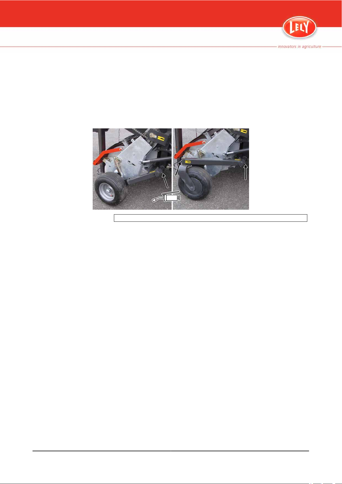
8.2.5 Grease the Pick-up Guide Wheels
• Requirements:
Grease pump
•
• Biodegradable grease (Total Biomultis SEP2 or equivalent)
1. Use the grease pump to grease the bearings of the pick-up guide
wheels.
Left: standard pick-up guide wheels - Right: swivelled pick-up guide wheels
Figure 56. Grease the Pick-up Guide Wheels
L-H007-1104EN
Maintenance 8-9
Page 90

8.2.6 Grease the Dog Clutch
• Requirements:
•
• Biodegradable grease (Total Biomultis SEP2 or equivalent)
1. Swivel away the cover of the grease point/inspection hole.
2. Use the grease pump to grease the dog clutch.
3. Swivel the cover back.
Grease pump
Figure 57. Grease the Dog Clutch
L-H007-1104EN
8-10 Maintenance
Page 91

8.2.7 Grease the Bearing of the Lateral Shaft
• Requirements:
Grease pump
•
• Biodegradable grease (Total Biomultis SEP2 or equivalent)
1. Open the cover of the external drive parts.
2. Use the grease pump to grease the bearing of the lateral shaft.
L-H007-1104EN
Figure 58. Grease the Bearing of the Lateral Shaft
Maintenance 8-11
Page 92

8.2.8 Grease the Cutting Unit
• Requirements:
Grease pump
•
• Biodegradable grease (Total Biomultis SEP2 or equivalent)
1. Open the cover of the cutting unit and the cover of the drive.
2. Use the grease pump to grease:
• the bearings of the rotor shaft
• the bearings of the swinging tine bars (optionally these grease points
• the rollers on the tine bar levers
• the gear wheel
are brought together by two grease nipple blocks on one of the tine
bars)
Left: internal greasing point - Right: external greasing point
Figure 59. Grease the Bearings of the Rotor Shaft
L-H007-1104EN
8-12 Maintenance
Page 93
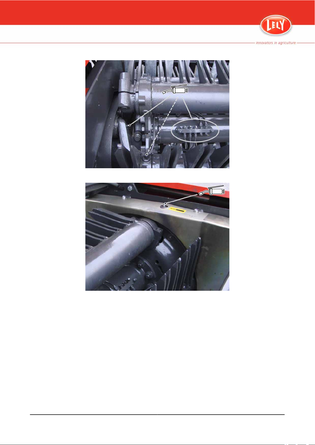
L-H007-1104EN
Figure 60. Grease the Bearings and Rollers of the Tine Bars
Figure 61. Grease the Gear Wheel of the Cutting Unit
Maintenance 8-13
Page 94

8.2.9 Grease the Bearing of the Pick-up Drive Sprocket
• Requirements:
Grease pump
•
• Biodegradable grease (Total Biomultis SEP2 or equivalent)
1. Use the grease pump to grease the bearing of the pick-up drive sprocket.
Figure 62. Grease the Bearing of the Pick-up Drive Sprocket
L-H007-1104EN
8-14 Maintenance
Page 95

8.2.10 Lubricate the Drive Chains of the Pick-up
• Requirements:
Oil can
•
• Lubricating oil
1. Use the oil can to lubricate the drive chain of the pick-up.
2. Make sure the drive chains runs smoothly.
L-H007-1104EN
Figure 63. Lubricate the Drive Chains of the Pick-up Unit
Maintenance 8-15
Page 96

8.2.11 Grease the Freewheel Clutch of the Pick-up
• Requirements:
Grease pump
•
• Biodegradable grease (Total Biomultis SEP2 or equivalent)
1. Lift the pick-up to the transport position.
2. Remove the plastic cover from the inspection hole.
3. Manually turn the pick-up until you can access the grease nipple through
the inspection hole.
4. Use the grease pump to grease the freewheel clutch.
5. Install the plastic cover on the inspection hole.
Figure 64. Grease the Freewheel Clutch of the Pick-up
L-H007-1104EN
8-16 Maintenance
Page 97

8.2.12 Lubricate the Running Wheels of the Floor Conveyor
• Requirements:
Oil can
•
• Lubricating oil
1. Use the oil can to lubricate the running wheels of the floor conveyor.
2. Make sure the running wheels run smoothly.
L-H007-1104EN
Figure 65. Lubricate the Running Wheels of the Floor Conveyor
Maintenance 8-17
Page 98

8.2.13 Grease the Bearings of the Floor Conveyor Drive Shaft
• Requirements:
Grease pump
•
• Biodegradable grease (Total Biomultis SEP2 or equivalent)
1. Use the grease pump to grease the bearings of the floor conveyor drive.
Figure 66. Grease the Bearings of the Floor Conveyor Drive Shaft
L-H007-1104EN
8-18 Maintenance
Page 99

8.2.14 Clean the Filter of the Air Brake System
If air brake system is available.
Requirements:
•
• Nitro cleaning agent
1. Push the locking tappet on both brackets and remove the slider.
2. Remove the locking tappet, O-ring, spring and filter cardridge.
3. If necessary, replace the damaged filter.
4. Use a Nitro cleaning agent to clean the filter.
5. Use compressed air to blow the filter clean.
6. Install the filter cardridge, spring, O-ring, slider and locking tappet.
7. Make sure the O-ring does not jam the slots of the slider.
L-H007-1104EN
Figure 67. Clean the Filters of the Air Break System
Maintenance 8-19
Page 100

8.2.15 Replace the Hydraulic Filter
• Requirements:
Collection container (minimum capacity: 3 litres)
•
• Hydraulic filter
1. Put the collection container underneath the hydraulic control block.
2. Remove the filter housing and clean the inside of the filter housing.
3. Replace the hydraulic filter.
4. Install the filter housing.
5. Remove the collection container from the area and dispose of the
drained oil as specified by local regulations.
Figure 68. Replace the Hydraulic Filter
L-H007-1104EN
8-20 Maintenance
 Loading...