

Page 1
Page 2

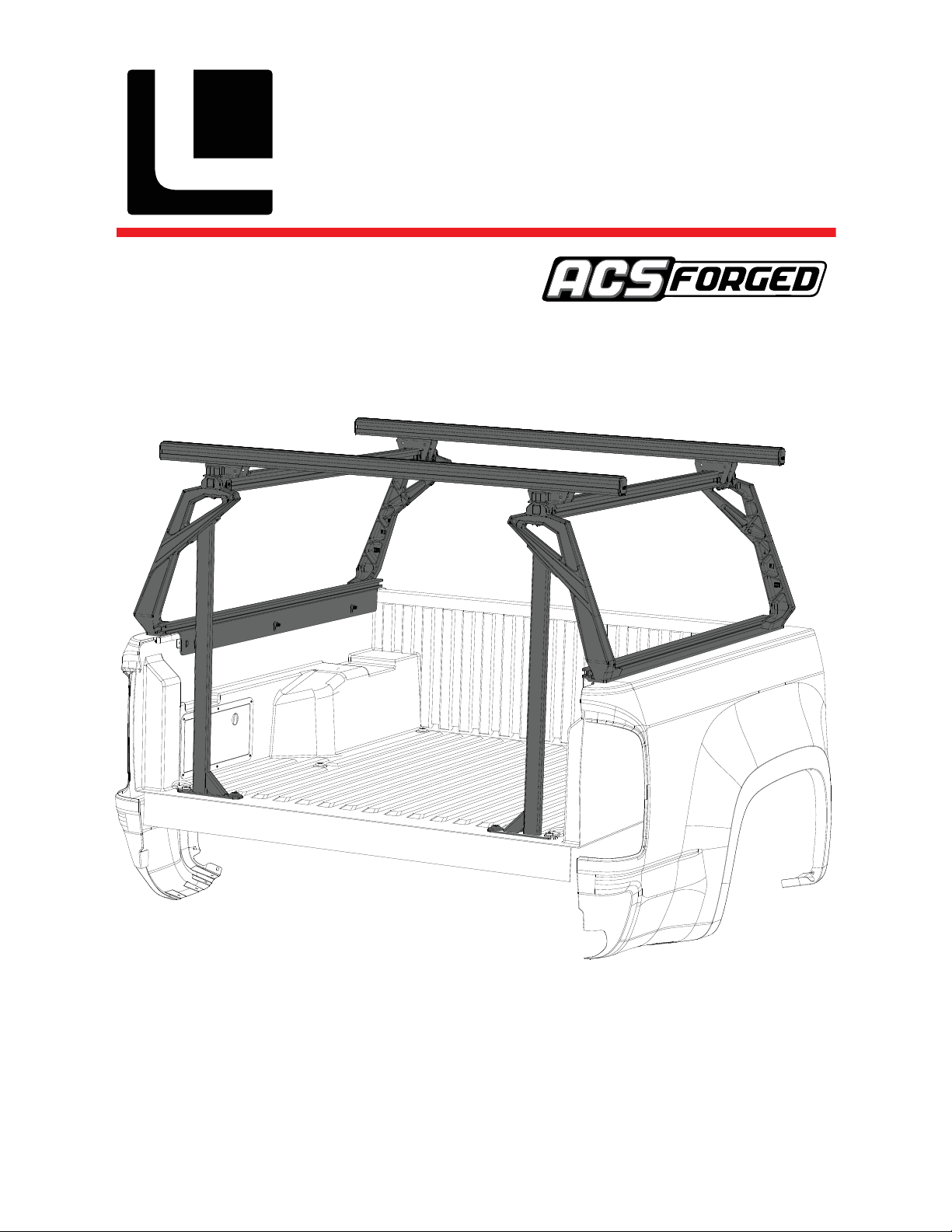
ASSEMBLY / INSTALLATION INSTRUCTIONS:
ACTIVE CARGO SYSTEM PART NUMBERS:
04-60-FA-1307 (2005-2015 Toyota Tacoma Short Bed]
04-73-FA-1328 (2005-2015 Toyota Tacoma Long Bed]
04-60-FA-1311 (2016-2020 Toyota Tacoma Short Bed]
04-73-FA-1329 (2016-2020 Toyota Tacoma Long Bed]
TOOLS REQUIRED
• Torque wrench
• 4mm HEX BIT socket
• 5mm HEX BIT socket
• 6mm HEX BIT socket
• 13MM WRENCH
TOOLS Included
• t40 torx
• t55 torx
INSTALLATION TIME
2-3 Hours
Basic knowledge of hand tools required
SKILL LEVEL
1
2 4
3= intermediate
INSTALLATION INSTRUCTIONS
3
LEITNERDESIGNS.COM | [email protected] | 949-395-3049
V1 | Page 2
Page 3
▼ READ BEFORE INSTALLING ACTIVE CARGO SYSTEM ▼
load BAR 60”
1. there are 2 different uprights clearly marked A & B. The A bracket is used on the passenger
side by the cab and on the drivers side by the tailgate. the B upright is used by the drivers
side cab and passengers side tailgate. Keep this in mind when assembling the ACS.
2. Don’t over-tighten bolts. All 10mm bolts = (40lb-ft) All 8mm bolts = (16ft-lb) All 6mm bolts = 10ft-lb) Rail clamp bolts {10ft-lb}
3. Note: drop in plastic bed liners will need to be removed before installing Active cargo system.
4. Lay down a large area of carpet or blankets as a work area to avoid scratching parts during assembly.
5. Two extra rivet nuts are included in case you make a mistake during assembly.
6. Take your time to do it right, measure twice, drill once.
`
7. Although the Active Cargo System is light having a friend to help is recommended.
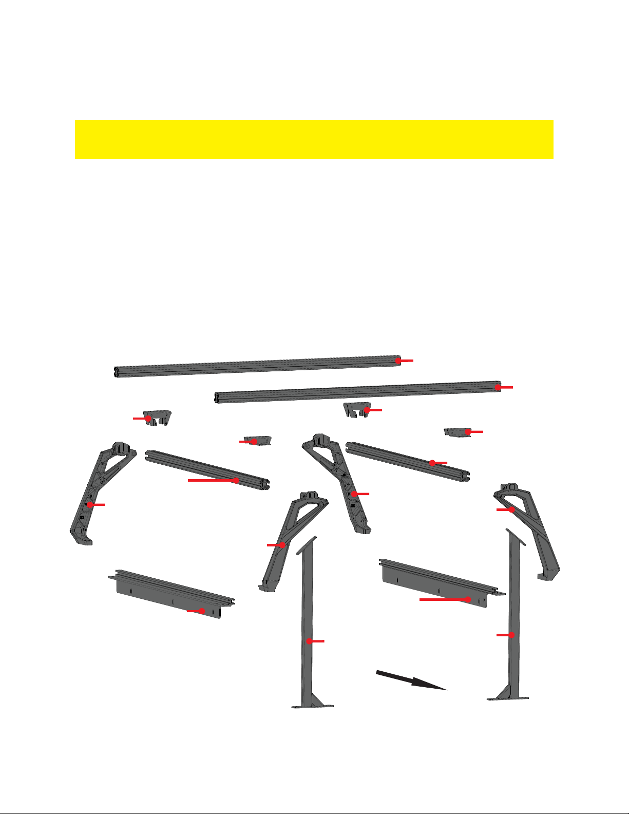
▼ ASSEMBLY OVERVIEW ▼
load BAR 60”
STATIONARY load
BAR BRACKET
“B” UPRIGHT
drivers side rail
TOP BAR
SLIDING load
BAR BRACKET
“A” UPRIGHT
“A” UPRIGHT
passenger side rail
tacoma down tube
STATIONARY load BAR BRACKET
SLIDING load
BAR BRACKET
TOP BAR
“B” UPRIGHT
tacoma down tube
TAILGATE
LEITNERDESIGNS.COM | [email protected] | 949-395-3049
V1 | Page 3
Page 4
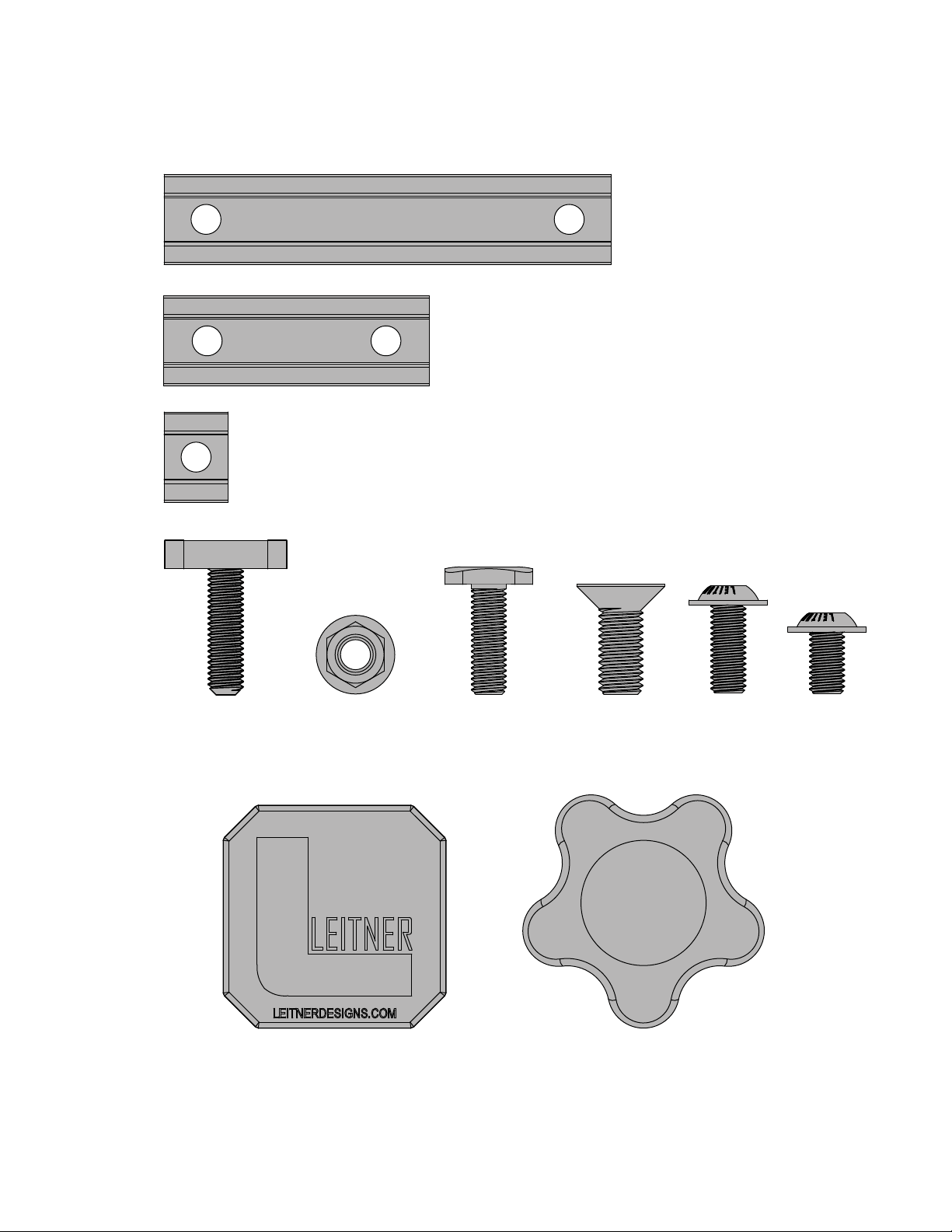
long t-nut
(x8)
short t-nut
(x4)
single t-nut
(x4)
▼ ACTIVE CARGO SYSTEM hardware ▼
rail bolt
(x6)
m8 nut
endcap
(x4)
(x6)
m8 t-bolt
(x4)
m10 x 25
(x8)
m8 x 20
(x12)
m8 x 14
(x16)
knob
(x4)
V1 | Page 4
Page 5
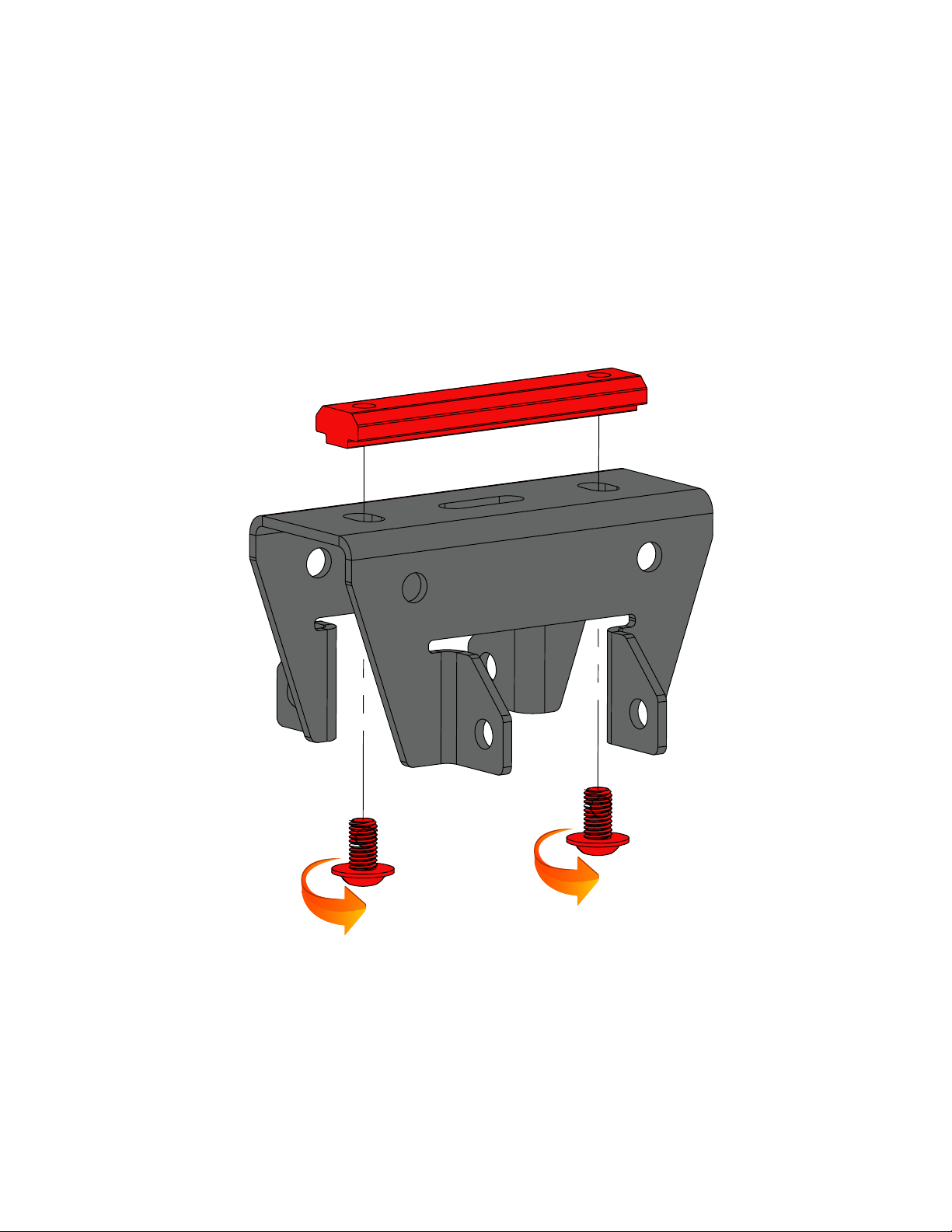
PREP: STATIONARY load BAR BRACKET
• Install 2 M8 x 14 bolts through bracket and thread into long T-nut. do not tighten at this time.
• Repeat steps below for second bracket.
• set aside for use in a later step.
long T-Nut
m8 x 14
V1 | Page 5
Page 6
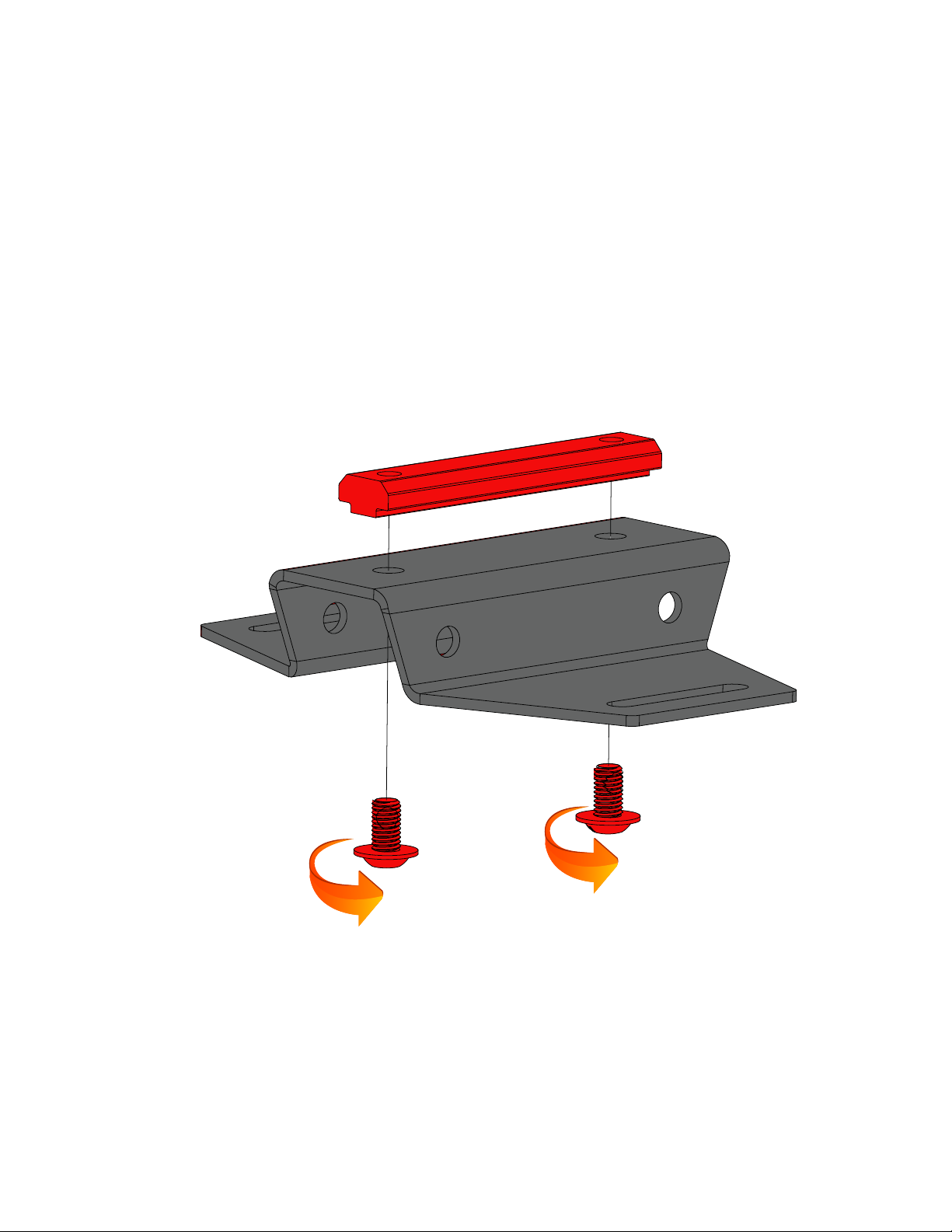
PREP: SLIDING load BAR BRACKETS
• Install 2 M8 x 14 bolts through bracket and thread into long T-nut. do not tighten at this time.
• Repeat steps below for second bracket.
• set aside for use in a later step.
long T-Nut
m8 x 14
V1 | Page 6
Page 7
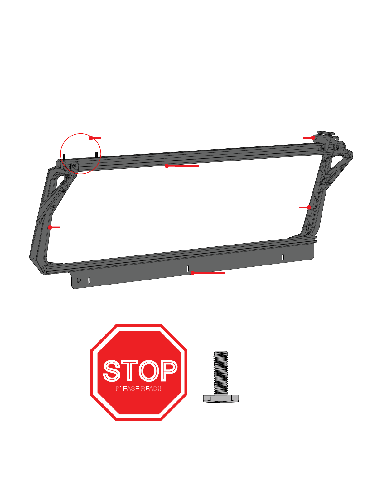
ASSEMBLE driver side: overview
• in the next few steps you will assemble the drivers side portion of the active cargo system.
• The illustration bellow shows what the part will look like when fully assembled. You can refer back to this
illustration at any time to clarify part location.
“A” UPRIGHT
M8 T-BOLTS
STATIONARY CROSS BAR BRACKET
TOP BAR
“B” UPRIGHT
DRIVER RAIL
STOP
PLEASE READ!!
m8 t-bolt
TWO (2) M8 T-BOLTS NEED TO BE SLIDE INTO THE UPPER MOST T-TRACK BEFORE ASSEMBLING THE UPRIGHTS.
IF YOU FORGET THIS STEP YOU WILL NOT BE ABLE TO INSTALL THE SLIDING LOAD BAR BRACKETS ON PAGE 22!!
WE WILL REMIND YOU TO DO THIS AGAIN SO DONT MESS THIS UP!!
V1 | Page 7
Page 8
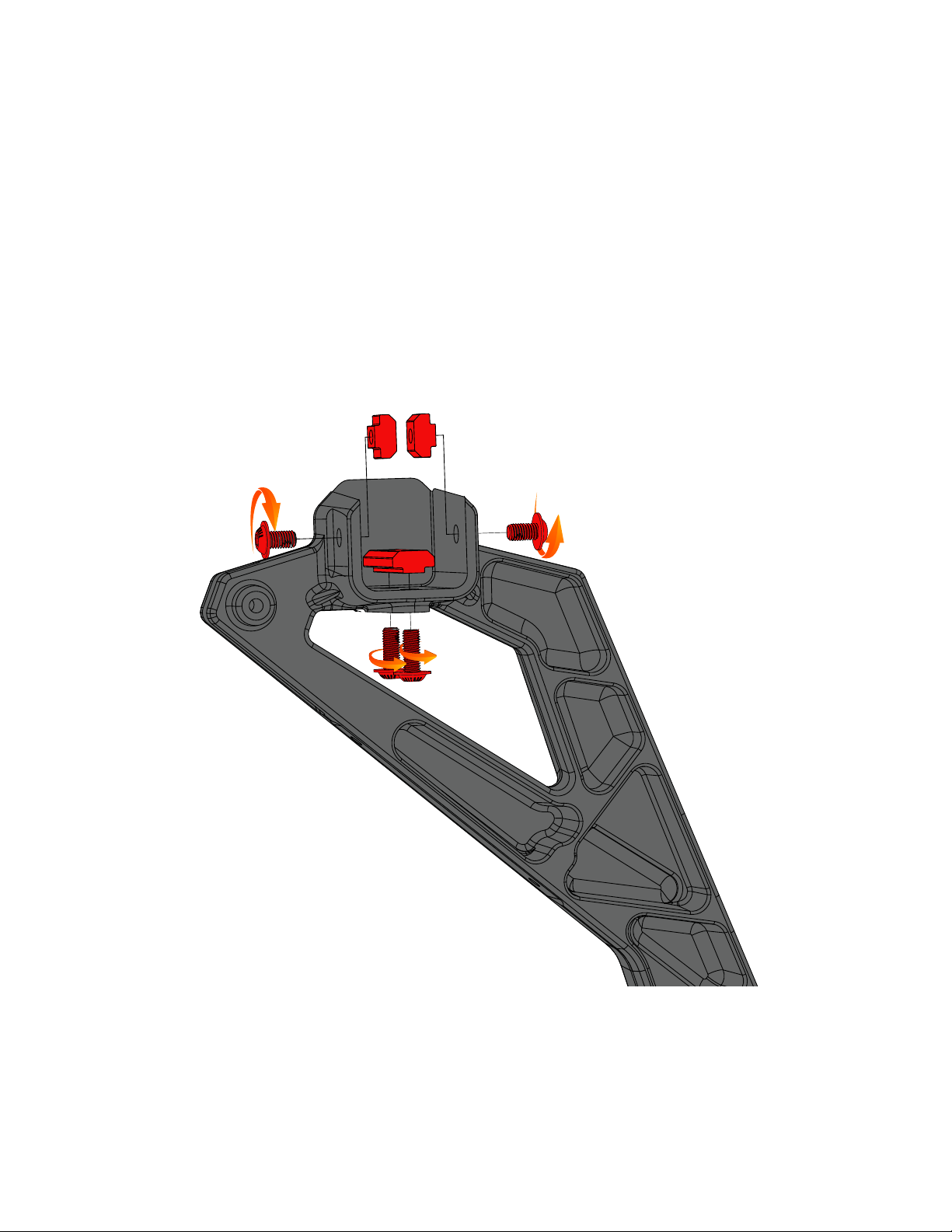
ASSEMBLE driver side: upright “A”
• Assemble upright marked “A” as shown in the following diagram.
•THREAD TWO M8 X 20 BOLTS INTO THE SHORT T-NUT. DO NOT TIGHTEN AT THIS TIME.
•THREAD ONE M8 X 16 BOLTS INTO EACH ONE OF THE SINGLE T-NUTS. DO NOT TIGHTEN AT THIS TIME.
• set aside for use in a later step.
{2x} SINGLE t-NUT
M8 X 14
M8 X 14
SHORT t-NUT
{2x} M8 X 20
V1 | Page 8
Page 9
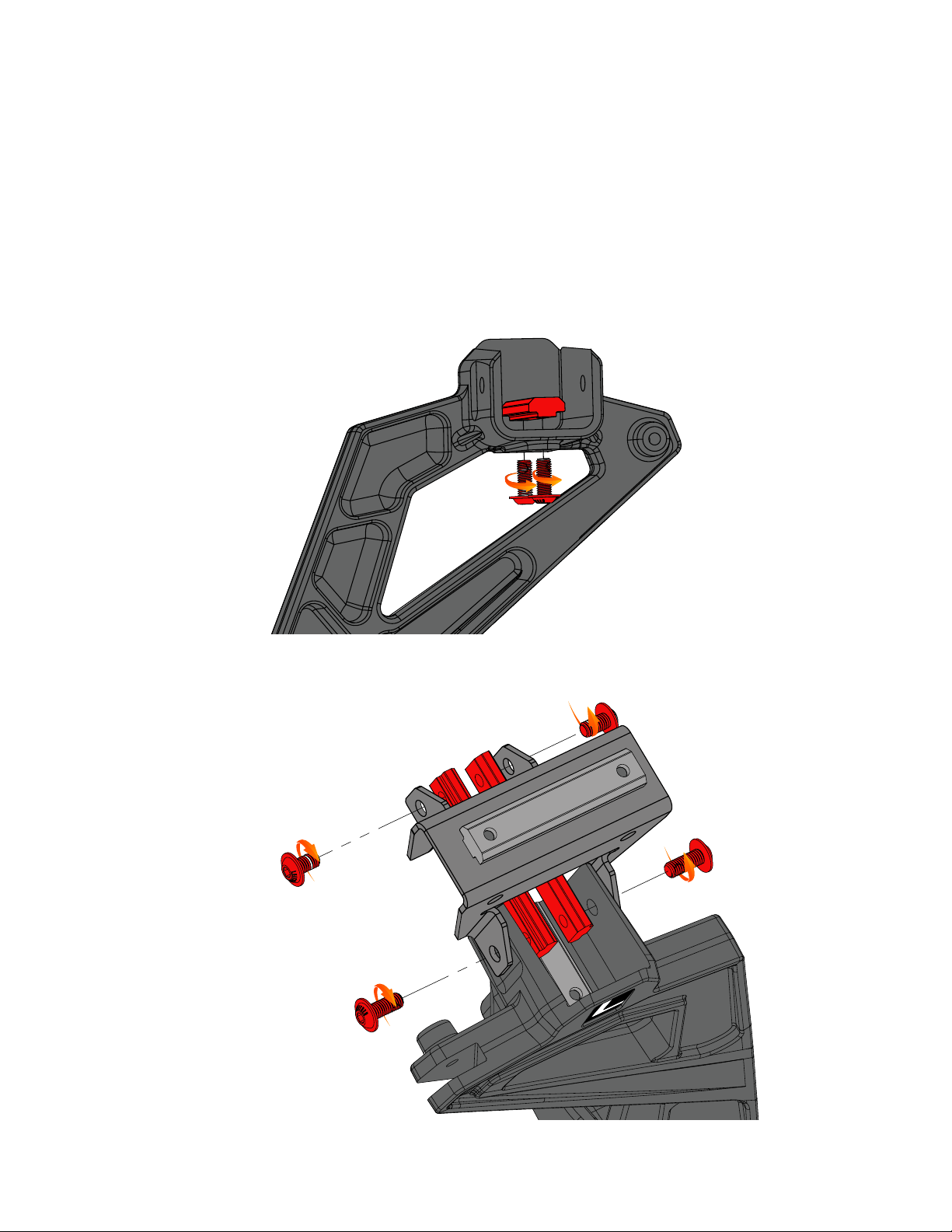
ASSEMBLE driver side: upright “B”
• Assemble upright marked “B” as shown in the folLOwing diagram.
•THREAD TWO M8 X 20 BOLTS INTO THE SHORT T-NUT. {FIG-A} DO NOT TIGHTEN AT THIS TIME.
•THREAD TWO M8X 20 BOLTS THROUGH CROSS BAR BRACKET AND UPRIGHT INTO LONG T-NUT {FIG-B} DO NOT TIGHTEN AT THIS TIME.
• THREAD TWO M8X 16 BOLTS THROUGH CROSS BAR BRACKET INTO LONG T-NUT {FIG-B} DO NOT TIGHTEN AT THIS TIME.
SHORT T-NUT
{2x} M8 X 20
M8 X 14
FIG-A
M8 X 14
{2X} long t-nut
M8 X 20
M8 X 20
FIG-B
V1 | Page 9
Page 10
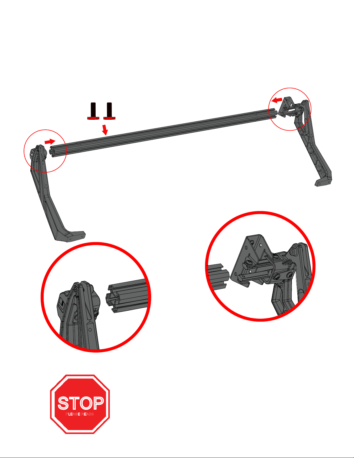
ASSEMBLE driver side: top bar
• attach a & B upright assembles to top bar as shown in illustration below. Do not tighten bolts at this time.
•NOTE: MAKE SURE YOU Slide THE TWO (2) T-BOLTS INTO THE UPPER MOST T-TRACK
1
2
DETAIL-1
STOP
PLEASE READ!!
DETAIL-2
TWO (2) M8 T-BOLTS NEED TO BE SLIDE INTO THE UPPER MOST T-TRACK
BEFORE ASSEMBLING THE UPRIGHTS. IF YOU FORGET THIS STEP YOU WILL
NOT BE ABLE TO INSTALL THE SLIDING LOAD BAR Brackets!
V1 | Page 10
Page 11
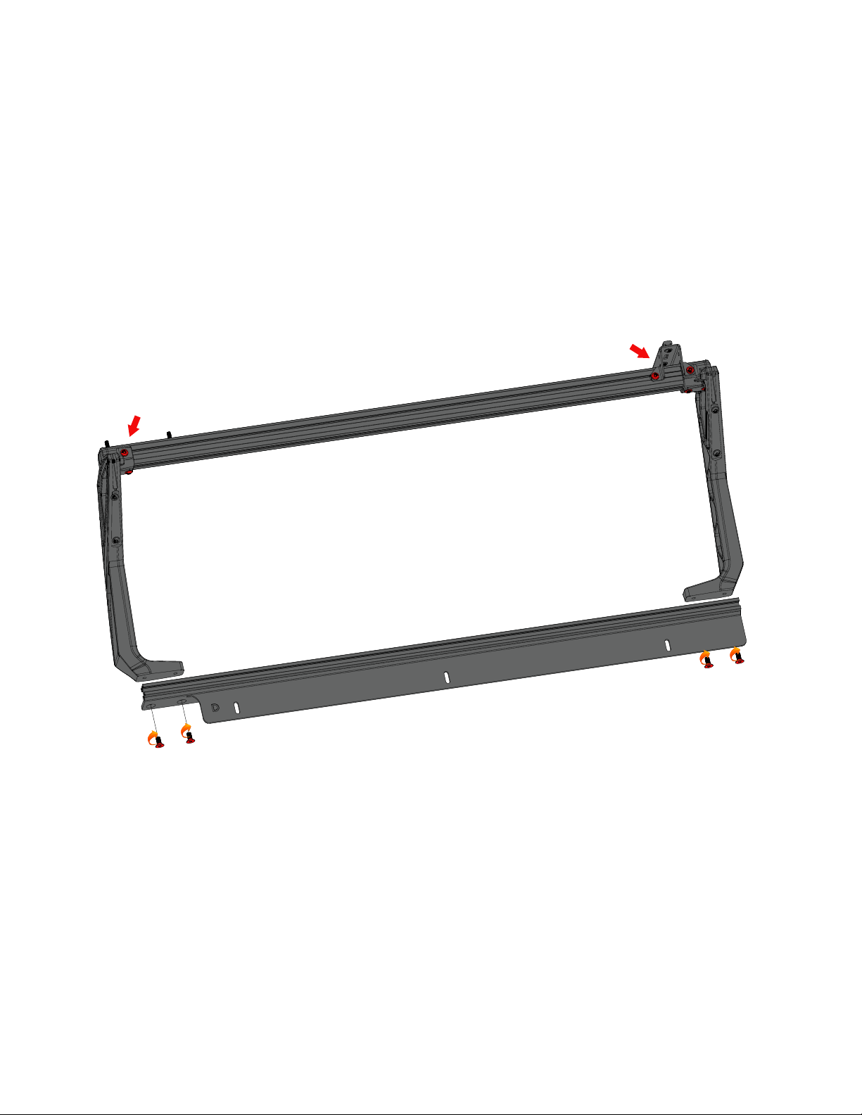
ASSEMBLE driver side: RAIL
• attach rail to uprights using four M10 X 25 screws. Torque to 40 Ft-lb using a 6mm allen wrench.
• Torque all M8 bolts installed in previous step to 18 ft-lb using a 5mm allen wrench.
• Important: Tighten M10x25 rail bolts first then torque the m8 bolts.
Tighten all M8 bolts to 16 ft-lb
m10 x 25
m10 x 25
Page 12
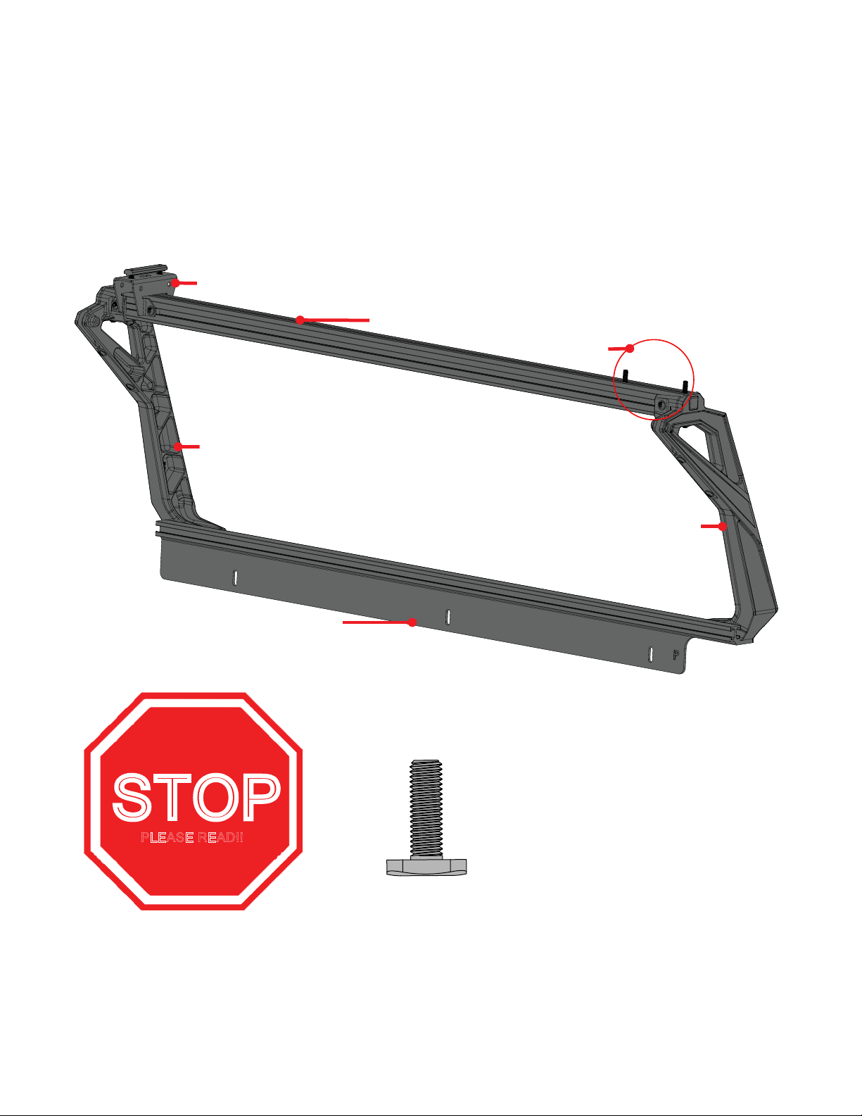
ASSEMBLE passenger side: overview
RAIL
• in the next few steps you will assemble the passenger side portion of the active cargo system.
• The illustration bellow shows what the part will look like when fully assembled. You can refer back to this
illustration at any time to clarify part location.
STATIONARY CROSS BAR BRACKET
TOP BAR
M8 T-BOLTS
“A” UPRIGHT
“B” UPRIGHT
STOP
PLEASE READ!!
m8 t-bolt
THE TWO (2) M8 T-BOLTS NEED TO BE SLIDE INTO THE UPPER MOST T-TRACK BEFORE ASSEMBLING THE
UPRIGHTS. IF YOU FORGET THIS STEP YOU WILL NOT BE ABLE TO INSTALL THE SLIDING LOAD BAR BRACKETS
ON PAGE 22!! WE WILL REMIND YOU TO DO THIS AGAIN SO DONT MESS THIS UP.
V1 | Page 12
Page 13
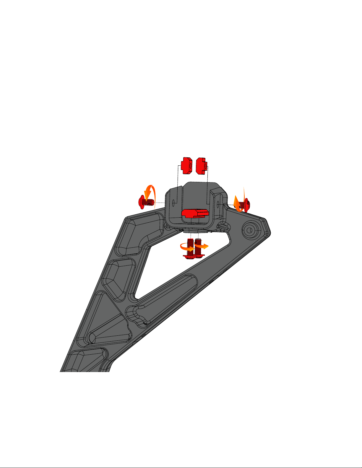
ASSEMBLE passenger side: upright “b”
• Assemble upright marked “b” as shown in the following diagram.
•THREAD TWO M8 X 20 BOLTS INTO THE SHORT T-NUT. DO NOT TIGHTEN AT THIS TIME.
•THREAD ONE M8 X 16 BOLTS INTO EACH ONE OF THE SINGLE T-NUTS. DO NOT TIGHTEN AT THIS TIME.
• set aside for use in a later step.
{2x} SINGLE t-NUT
M8 X 14
M8 X 14
SHORT t-NUT
{2x} M8 X 20
V1 | Page 13
Page 14
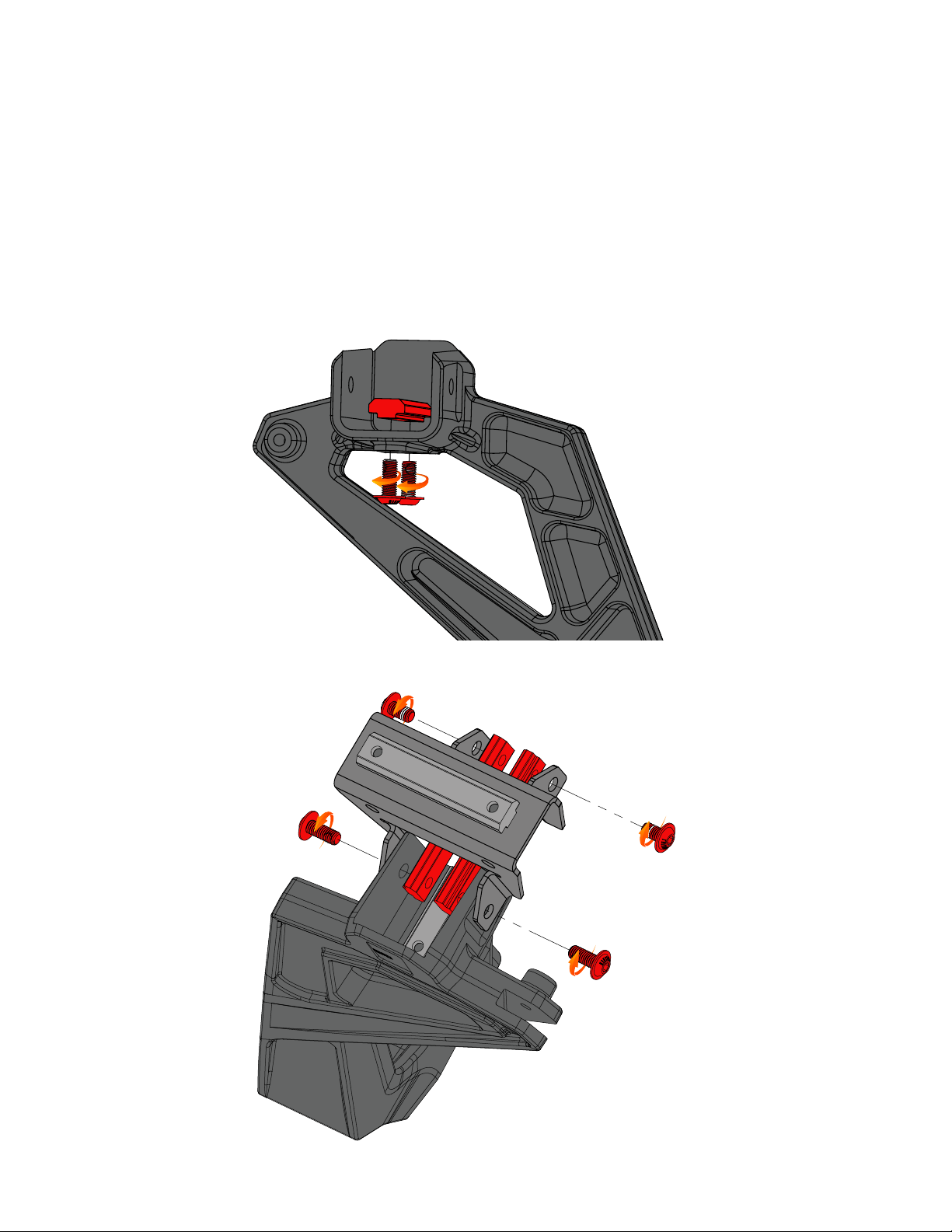
ASSEMBLE passenger side: upright “A”
• Assemble upright marked “A” as shown in the folLOwing diagram.
•THREAD TWO M8 X 20 BOLTS INTO THE SHORT T-NUT. {FIG-A} DO NOT TIGHTEN AT THIS TIME.
•THREAD TWO M8X 20 BOLTS THROUGH CROSS BAR BRACKET AND UPRIGHT INTO LONG T-NUT {FIG-B} DO NOT TIGHTEN AT THIS TIME.
• THREAD TWO M8X 16 BOLTS THROUGH CROSS BAR BRACKET INTO LONG T-NUT {FIG-B} DO NOT TIGHTEN AT THIS TIME.
SHORT T-NUT
{2x} M8 X 20
M8 X 20
FIG-A
M8 X 14
{2X} long t-nut
M8 X 14
M8 X 20
FIG-B
V1 | Page 14
Page 15
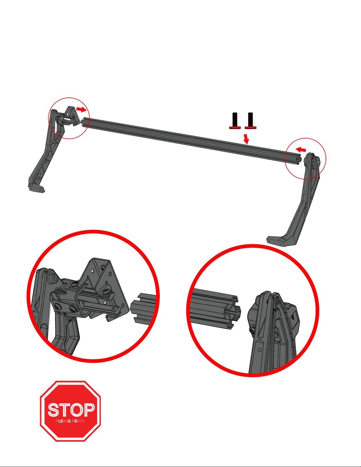
ASSEMBLE passenger side: top bar
• attach a & B upright assembles to top bar as shoWN in illustration below. Do not tighten bolts at this time.
•NOTE: MAKE SURE YOU SLide THE TWO (2) T-BOLTS INTO THE UPPER MOST T-TRACK
2
1
DETAIL-2
STOP
PLEASE READ!!
DETAIL-1
TWO (2) M8 T-BOLTS NEED TO BE SLIDE INTO THE UPPER MOST T-TRACK
BEFORE ASSEMBLING THE UPRIGHTS. IF YOU FORGET THIS STEP YOU WILL
NOT BE ABLE TO INSTALL THE SLIDING LOAD BAR Brackets!
V1 | Page 15
Page 16
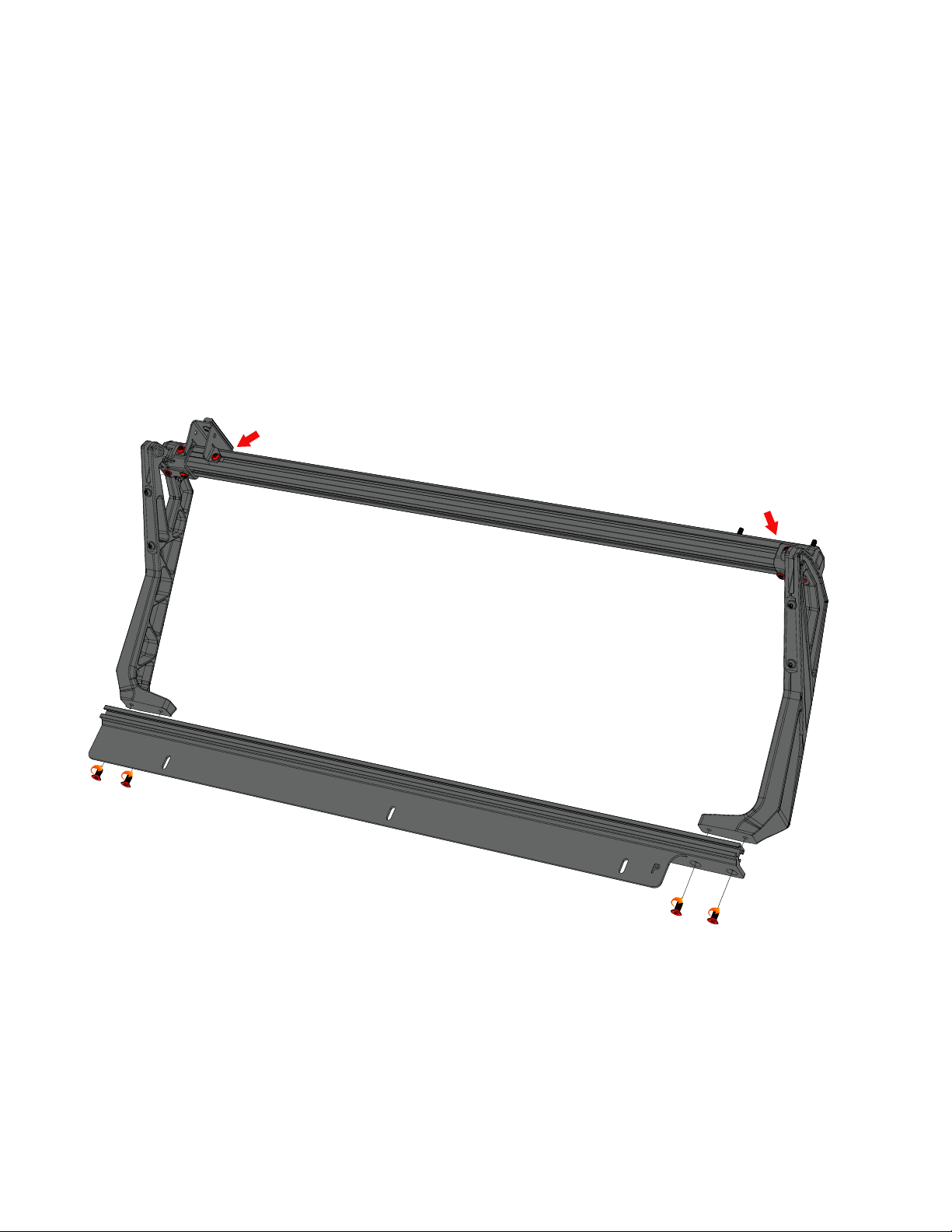
ASSEMBLE passenger side: RAIL
• attach rail to uprights using four M10 X 25 screws. Torque to 40 Ft-lb using a 6mm allen wrench.
• Torque all M8 bolts installed in previous step to 16 ft-lb using a 5mm allen wrench.
•
Important: Tighten M10x25 rail bolts first then torque the m8 bolts.
Tighten all M8 bolts to 16 ft-lb
m10 x 25
m10 x 25
V1 | Page 16
Page 17
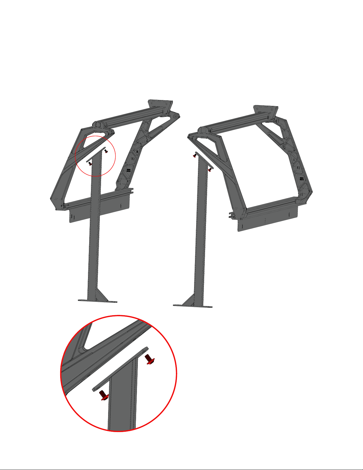
ASSEMBLE: Tacoma down tubes
• Remove two M8x14 screws from the upright. Using these screws attach the Tacoma down tubes as shown.
V1 | Page 17
Page 18
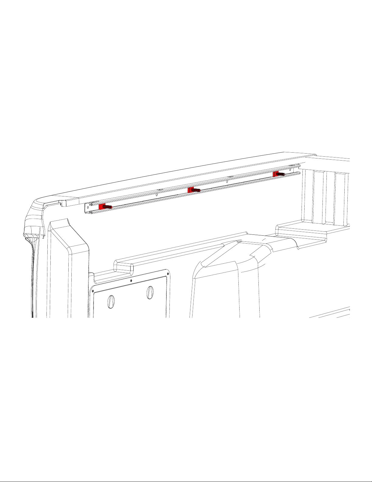
prep: TACOMA BED
• Install three rail bolts into both the passenger and drivers side trail rails.
• note: you will need to remove the factory tie downs first.
V1 | Page 18
Page 19
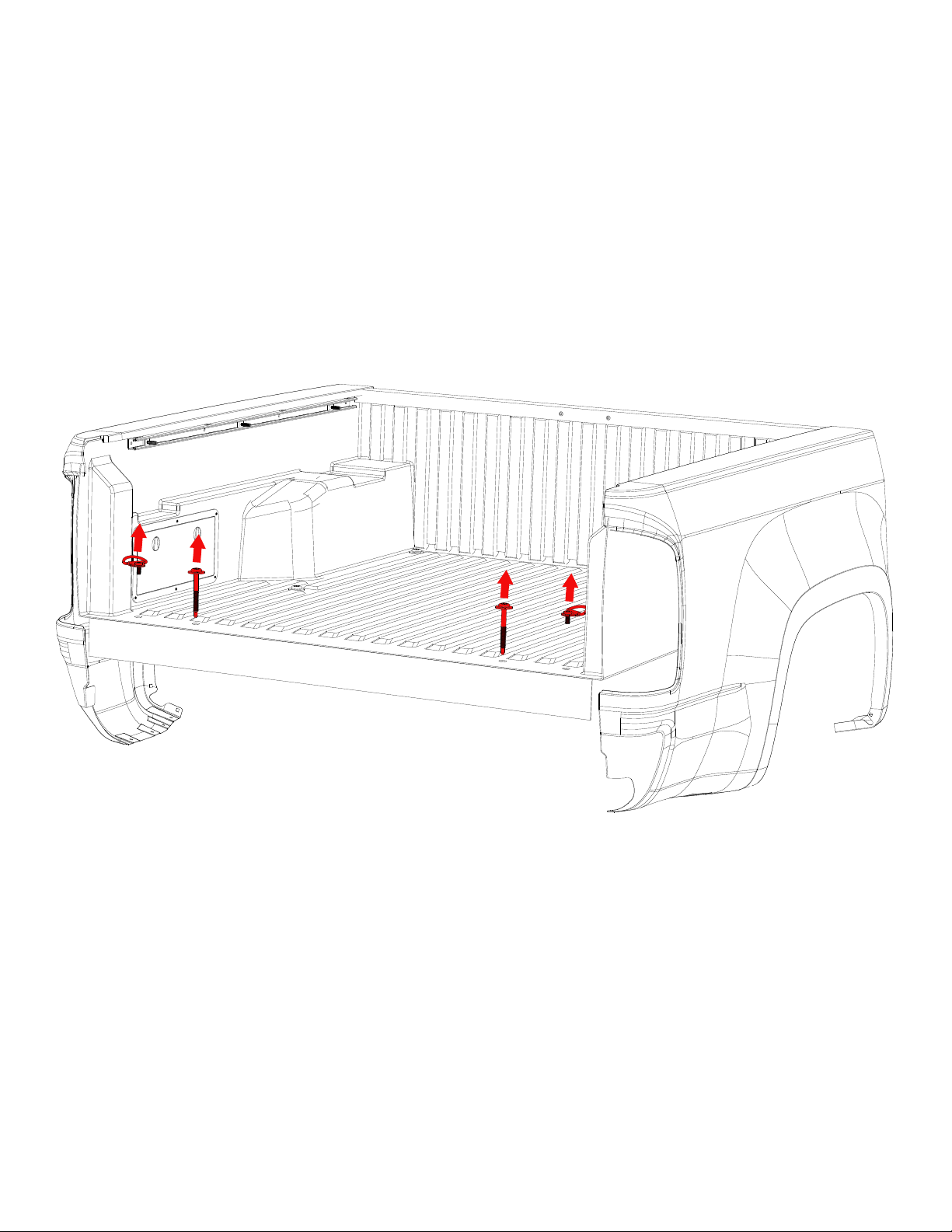
prep: TACOMA BED
•REMOVE THE 2 REAR BED BOLTS USING A T55 TORX WRENCH. SET ASIDE FOR USE LATER.
• REMOVE THE TWO REAR TIE DOWN RINGS USING A T40 TORX WRENCH. SET ASIDE FOR USE LATER
V1 | Page 19
Page 20
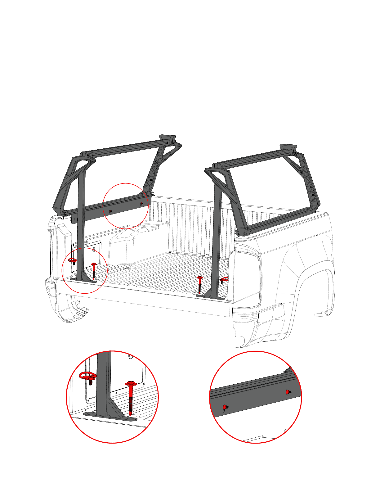
INSTALL: RACK TO TRUCK
• Place the drivers side assembly onto the bed rail of the truck. The “D” will be toward the tailgate.
• Align the holes in the Upright supports with the holes in the floor of the trucked, Replace bolts. [Detail - A]
• Using three M8 nut attach the assembly to the truck. [detail - B]
• Repeat steps for passenger side.
B
A
DETAIL - A
DETAIL - A
DETAIL - b
V1 | Page 20
Page 21
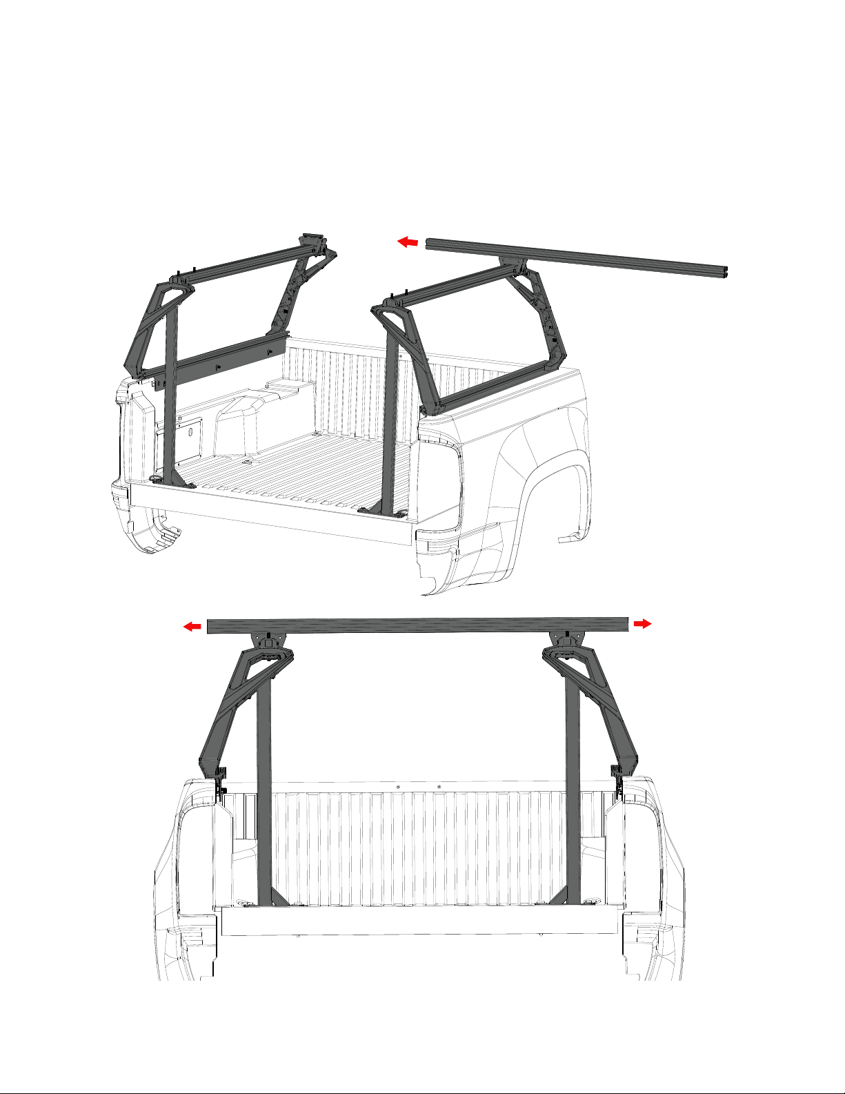
ASSEMBLE: front load BAR TO BRACKETS
• SLIDE THE 60” long load BARS ONTO THE T-nuts IN THE stationary load BAR BRACKETS and center them on the rack.
• Tighten the four M8 screws on the underside of the bracket using a 5mm allen wrench.
V1 | Page 21
Page 22
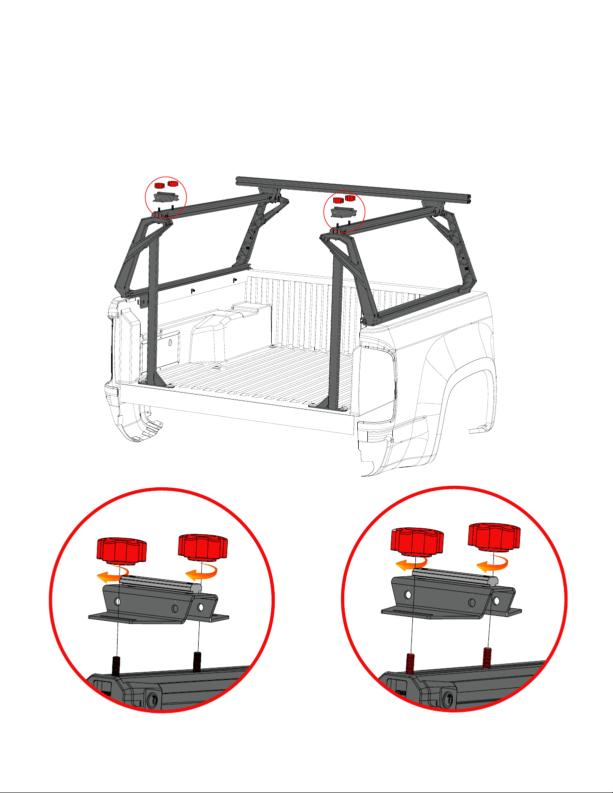
ASSEMBLE: SLIDING LOAD BAR BRACKETS
• USING 2 rubber knobs per side, SECURE THE rear CROSS BAR BRACKET AS FAR rearward AS POSSIBLE. [Detail A - b]
A
b
DETAIL-A
DETAIL-b
V1 | Page 22
Page 23
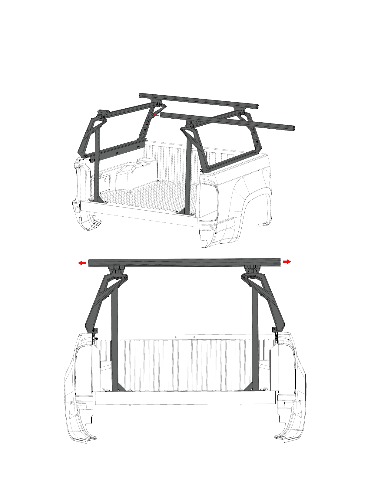
ASSEMBLE: REAR LOAD BAR TO BRACKETS
• SLIDE THE 60” long LOAD BARS ONTO THE T-nuts IN THE REAR LOAD BAR BRACKETS and center them on the rack.
V1 | Page 23
Page 24
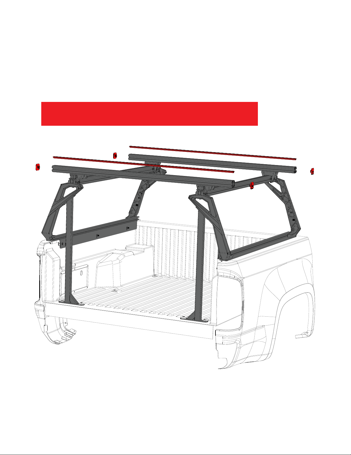
finish: install end caps and rubber tread strip
• Install the rubber tread strip into the upper cross bar channel by pushing it into the t-slot with the palm of your hand. Note:
some trimming of the rubber tread strip might be necessary.
• Install the four end caps into the ends of the cross bars.
check all fasteners installed in previous
steps to ensure they are properly tightened
V1 | Page 24
Page 25

use guidelines
When using Leitner Designs carriers and accessories, the user must understand the precautions.
The points listed below will assist you in using the rack system and will encourage safety.
•For quality fits and safety, use only the recommended rack or accessories. Do not assume a rack
will fit, always check the current Fit Guide when obtaining a new vehicle.
•The maximum load is not to be exceeded. (250# off road – 500# on road). However, this limit is
always subordinate to the maximum load recommended by the manufacturer of the vehicle itself.
It is always the lower maximum recommended load that applies. Max truck load = load carrier
weight + any fitted carrier accessories + the weight of the load itself.
•high speed off road driving even with a light load can cause damage to the rack, accessories
and vehicle body. Damage caused by high speed driving and abuse is not covered under
warranty.
•Make sure all knobs, bolts, screws, straps, and locks are firmly attached, tightened and locked
before every trip. Knobs, bolts, screws, straps and locks must be periodically inspected for signs
of wear, corrosion, and fatigue. Check your load at stops during the trip to ensure continued
fastening security.
•Check local and state laws governing projection of objects beyond the perimeter of a vehicle.
Be aware of the width and height of your cargo since low clearance branches, bridges, and
parking garages can affect the load. All cargo will affect the vehicle’s driving behavior. Never
drive with any lock, knob or rack in an open or unlocked position. All long loads such as, but
not limited to, sailboards, surfboards, kayaks, canoes, and lumber must be tied down front and
rear to the bumpers or tow hooks of the vehicle.
•All locks must be turned and moved periodically to ensure smooth operation. Use graphite or
dry lubricant to help this. Leitner designs locks are designed to deter vandalism and theft but
should not be considered theft proof. Remove valuable gear if your vehicle is unattended for an
extended period. Place at least one key in the glove compartment.
•For safety to your vehicle and rack system, obey all posted speed limits and traffic cautions.
Adapt your speed to the conditions of the road and the load being carried.
•Do not use Leitner Designs load carriers and accessories for purposes other than those
for which they were designed. Do not exceed their carrying capacity. Failure to follow these
guidelines or the product’s instructions will void the warranty.
V1 | Page 25
Page 26

Warranty
Leitner Designs warrants product to be free from defects in material and workmanship, for
terms specified below, provided there has been normal use and proper maintenance. All remedies
under this warranty are limited to the repair or replacement of any item found by the factory to
be defective within the time period specified. If you have a warranty claim, first you must call our
factory at the number below for instructions. You must retain proof of purchase and submit
a copy with any items returned for warranty work. Upon completion of warranty work, if any,
we will return the repaired or replaced item or items to you freight prepaid. Damage to our
products caused by accidents, Fire, vandalism, negligence, mis-installation, misuse, Acts of God,
or by defective parts not manufactured by us, is not covered under this warranty.
THE WARRANTY TIME PERIOD IS AS FOLLOWS: (2) TWO YEARS FROM DATE OF PURCHASE.
high speed off road driving even with a light load can cause damage to the rack, accessories
and vehicle body. Damage caused by high speed off road driving and abuse is not covered
under warranty.
ANY IMPLIED WARRANTIES OF MERCHANTABILITY AND/OR FITNESS FOR A PARTICULAR PURPOSE CREATED
HEREBY ARE LIMITED IN DURATION TO THE SAME DURATION AND SCOPE AS THE EXPRESS WRITTEN WARRANTY.
OUR COMPANY SHALL NOT BE LIABLE FOR ANY INCIDENTAL OR CONSEQUENTIAL DAMAGE.
Some states do not allow limitations on how long an implied warranty lasts, or the exclusion or
limitation of incidental or consequential damages, so the above limitations or exclusions may not
apply to you. This warranty gives you specific legal rights, and you may also have other rights
that vary from state to state.
FOR WARRANTY ISSUES WITH THIS PRODUCT PLEASE CALL LEITNER DESIGNS CUSTOMER SERVICE 949-395-
3049 or email us at [email protected]
V1 | Page 26
 Loading...