

Page 1

Page 2

Trademarks and Copyright
ADAC, ADCOE, BOS, Broadcast Operating system, CCS, DigiBus, DigiPeek,
Digital Glue, DigiWorks, DTV Glue, Engineering The Big Picture,
EventWORKS, EZ HD, Focused on the Future, Genesis, HDTV Glue,
HEDCO, Innovision, ISIS, JUNO, LeFont, Leitch, Leitch Network Systems,
LNS, LogoMAX, LogoMotion, MediaFile, MediaPort, MIX BOX, Monarch,
Motion File, OPUS, PanelMAPPER, Pilot, Portal, PROM-Slide,
RouterWORKS, StillFile, Still Net, Te k n i c h e , Unilock, VIA, ViewGuard,
Whiplash2, Xplus, and Leitch XPRESS are trademarks and/or registered
trademarks of Leitch Te c h n o l o g y Corporation in the United States, Canada,
and/or other countries.
All other trademarks are the property of their respective owners.
Copyright 2002, Leitch Incorporated. All rights reserved. This publication
supersedes all previous releases. Printed in Canada.
Page 3

DEC-6001
Digital Comb-Filter
Decoder
User Manual
Edition B
January 2002
Page 4

Page 5

Purpose
Audience
Writing Conventions
Preface
This manual details the features, installation procedures, operational
procedures, and specifications of the Digital Comb-Filter Decoder.
This manual is written for technicians and operators responsible for
installation, setup, and/or operation of Digital Comb-Filter Decoder.
To enhance your understanding, the authors of this manual have
adhered to the following text conventions:
Bold Indicates dialog box, property sheet, field, button, checkbox,
listbox, combo box, menu, submenu, window, list, and
selection names.
DEC-6001 User Manual iii
Italics Indicates email addresses, names of books and publications,
and first instances of new terms and specialized words that
need emphasis.
CAPS Indicates a specific key on the keyboard, such as ENTER,
TAB, CTRL, ALT, DELETE.
Code
> Indicates direction of navigation through a hierarchy of
hyperlink
Indicates variables or command-line entries, i.e., a DOS entry,
something you type into a field, etc.
menus and windows.
Indicates a jump to another location in the document or
elsewhere (such as a website).
Page 6

Revision History
Edition Date Revision History
Issue 1 November 1997 Previous release
B January 2002 Formatting changes
iv DEC-6001 User Manual
Page 7

Unpacking/Shipping Information
This product has been carefully inspected, tested and calibrated before
shipment to ensure years of stable and troublefree service. Please check
the equipment for any visible damage which may have occurred during
transit.
Please confirm that all items listed on the packing list have been
received. If any item on the packing list is missing, please contact your
Leitch dealer. If any item is damaged please contact the carrier. Ensure
that all packaging material is removed from the product and its
associated components before installing the unit.
It is suggested that you keep at least one set of original Leitch packaging,
in the event that a product needs to be returned for service. If the
original packaging is not available, you can purchase replacement
packaging from Leitch at a modest cost or supply your own packaging as
long as it meets the following criteria:
• Packaging must be able to withstand the product weight.
• Product must be held rigid within the packaging.
• There must be at least two inches of space between the product
and the container.
• The corners of the product must be protected.
Products that are being returned to Leitch for servicing should be
shipped pre-paid in the original packaging material if possible. If the
product is still within the warranty period, the product will be returned
by pre-paid shipment after servicing.
Installation Information
If this product is rack mountable, it should be mounted in an
appropriate rack using the rack mounting positions and rear support
guides provided. It is recommended that each frame be connected to a
separate electrical circuit for protection against circuit overloading. If
this product relies on forced air cooling, it is recommended that all
obstructions to the air flow be removed prior to installing the frame in
the rack.
If this product has a provision for external earth grounding, it is
recommended that the frame be grounded to earth via the protective
earth ground on the rear panel.
DEC-6001 User Manual v
Page 8

Important Safety Instructions
Review the following safety precautions to avoid injury and prevent
damage to this product or any products connected to it. Read these
instructions. Keep these instructions. Heed all warnings. Follow all
instructions.
Servicing
Only qualified personnel should perform service procedures. Refer all
servicing to qualified service personnel. Servicing is required when the
apparatus has been damaged in any way, such as power-supply cord or
plug is damaged, liquid has been spilled or objects have fallen into the
apparatus, the apparatus has been exposed to rain or moisture, does not
operate normally, or has been dropped.
Safety Terms and Symbols
Terms and Symbols in This Manual
WARNING:
Statements identifying conditions or practices that can result in
personal injury or loss of life: High voltage is present. Uninsulated
dangerous voltage within the product’s enclosure may be sufficient
to constitute a risk of electric shock to persons.
CAUTION:
Statements identifying conditions or practices that can result in
damage to the equipment or other property: Important operating
and maintenance (servicing) instructions in the literature
accompanying the product.
Terms and Symbols on the Product
DANGER:
High voltage and indicates a personal injury hazard immediately
vi DEC-6001 User Manual
accessible as one reads the marking.
WARNING:
Indicates a personal injury hazard not immediately accessible as
one reads the marking.
CAUTION:
Indicates a hazard to property including the product or to take
attention and refer to the manual.
Page 9

Injury Precautions
Protective ground (earth) terminal.
Fuse:
Replace with same type and rating of fuse.
Observe precautions for handling electrostatic-sensitive devices.
WARNING!
To reduce the risk of electric shock, do not expose this apparatus to
rain or moisture.
CAUTION
RISK OF ELECTRIC SHOCK
DO NOT OPEN
WARNING!
Potentially lethal voltages are present within this product’s frame
during normal operation. The AC power cord must be
disconnected from the frame before the top panel is removed. (In
frames with multiple power supplies, remove ALL power cords.)
Power should not be applied to the frame while the top is open,
unless properly trained personnel are servicing the unit.
[PL Poland] Przod zdjeciem pokrywy wyciagnac wtyczke z gniazda
sieciowego.
[French] AVIS: RISQUE DE CHOC ELECTRIQUE - NE PAS
OUVRIR. INSTALLER SUR SUPPORT DE MONTAGE
SEULEMENT.
DEC-6001 User Manual vii
Page 10

viii DEC-6001 User Manual
AVIS - Risque de choc electrique. Ne pas
ouvrir.
Page 11

Use Proper Power Cord
To avoid fire hazard, use only the power cord specified for this
product.
Ground the Product
Do not defeat the safety purpose of the polarized or grounding-type
plug. A polarized plug has two blades with one wider than the other.
A grounding type plug has two blades and a third grounding prong.
The wide blade or the third prong are provided for your safety.
When the provided plug does not fit into your outlet, consult an
electrician for replacement of the obsolete outlet.
[United Kingdom] WARNING: THIS APPLIANCE MUST BE
EARTHED.
[Sweden] APPARATEN SKALL ANSLUTAS TILL JORDAT
UTTAG NÄR DEN ANSLUTS TILL ETT NÄTVERK.
Do Not Operate Without Covers
To avoid electrical shock or fire hazard, do not operate this product
with covers or panels removed.
Use Proper Fuse
To avoid fire hazard, use only the fuse type and rating specified for
this product.
Do Not Operate in Wet/Damp Conditions
To reduce the risk of fire or electric shock, do not expose this
apparatus to rain or moisture
Do Not Operate in an Explosive Atmosphere
To avoid injury or fire hazard, do not operate this product in an
explosive atmosphere.
Avoid Exposed Circuitry
To avoid injury, remove jewelry such as rings, watches, and other
metallic objects. Do not touch exposed connections and
components when power is present.
DEC-6001 User Manual ix
Page 12
Product Damage Precautions
Use Proper Power Source
Do not operate this product from a power source that supplies
more than the specified voltage.
Use Proper Voltage Setting
Before applying power, ensure that the line selector is in the proper
position for the power source being used.
Provide Proper Ventilation
To prevent product overheating, provide proper ventilation.
Do Not Block Any Ventilation Openings
Do not block any of the ventilation openings. Install in accordance
with the manufacturer’s instructions.
Only Use Attachments/Accessories Specified by the Manufacturer
Do Not Operate With Suspected Failures
Refer all servicing to qualified service personnel. Servicing is
required when the apparatus has been damaged in any way, such as
power-supply cord or plug is damaged, liquid has been spilled or
objects have fallen into the apparatus, the apparatus has been
exposed to rain or moisture, does not operate normally, or has been
dropped.
For Products with Multiple Power Cords:
CAUTION: This unit can have more than one power supply cord.
To de-energize the internal circuitry, disconnect all power cords
before servicing.
[Norwegian] ADVARSEL: Utstyret kan ha mere ennn en
tilførselsledning. For å gjore interne deler spennigsløse må alle
tilførselsledningene trekkes ut.
[Sweden] VARNING: Denna apparat har mer än en nätanslutning.
Samtliga nätkablar måste bortkopplas för att göra de interna
kretsarna spänningsfria.
Do not use this apparatus near water
Do not expose this apparatus to dripping or splashing water.
Ensure that no objects filled with liquid, such as vases or cups, are
placed on the apparatus.
x DEC-6001 User Manual
Page 13
Clean only with a dry cloth
Keep Product Away from Heat Sources
Do not install near any heat sources such as radiators, heat registers,
stoves, or other apparatus (including amplifiers) that produce heat.
Install Near Socket Outlet
The equipment shall be installed near the socket outlet, and a
disconnect device shall be easily accessible.
Protect the Power Cord
Protect the power cord from being walked on or pinched
particularly at plugs, convenience receptacles, and the point where
they exit from the apparatus.
Unplug this Apparatus During Lightning Storms
Unplug this apparatus during lightning storms or when unused for
long periods of time. Note: A UPS or power surge suppressor could
be used as an alternative.
Attention:
Observe precautions for handling electrostatic-sensitive devices.See
“Preventing Electrostatic Discharge” below for details.
Fuse Replacement:
CAUTION: FOR CONTINUED PROTECTION AGAINST RISK
OF FIRE, REPLACE ONLY WITH THE SAME TYPE OF FUSE.
[French]ATTENTION: REMPLACER UNIQUEMENT PAR UN
FUSIBLE DE MEME TYPE.
DEC-6001 User Manual xi
Page 14
Battery Use Warnings
CAUTION:
DANGER OF EXPLOSION IF BATTERY IS INCORRECTLY
PLACED. REPLACE ONLY WITH THE SAME OR
EQUIVALENT TYPE RECOMMENDED BY THE
MANUFACTURER. DISCARD USED BATTERIES ACCORDING
TO THE MANUFACTURER’S INSTRUCTIONS.
[FI Finland] VAROITUS: Paristo voi rajahtaa, jos se on
virheellisesti asennettu. Vaihda paristo ainoastaan valmistajan
suosittelemaan tyyppun. Havita kaytetty paristo valmistajan
ohjeiden mukaisesti.
[SE Sweden] VARNING: Explosionsfara vid felaktigt batteribyte.
Anvand samma batterityp eller en eller en ekvivalent typ som
rekommenderas av tillverkaren. Kassera anvant batteri enligt
fabrikantens instruktion.
[D Denmark]
Advarsel! Lithiumbatteri. Eksplosionsfare ved fejlagtig handtering.
Udskiftning ma kun ske med batteri af samme fabrikat oq type.
Lever det brugte batteri tilbage till leverandoren.
[KO Korean]
xii DEC-6001 User Manual
Page 15

Preventing Electrostatic Discharge
CAUTION: Electrostatic discharge (ESD) can damage components
in the product. To prevent ESD, observe these precautions when
directed to do so:
Use a Ground Strap. Wear a grounded antistatic wrist strap to
discharge the static voltage from your body while installing or
removing sensitive components.
Use a Safe Work Area. Do not use any devices capable of generating
or holding a static charge in the work area where you install or
remove sensitive components. Avoid handling sensitive
components in areas that have a floor or benchtop surface capable
of generating a static charge.
Handle Components Carefully. Do not slide sensitive components
over any surface. Do not touch exposed connector pins. Handle
sensitive components as little as possible.
Transport and Store Carefully. Transport and store sensitive
components in a static-protected bag or container.
DEC-6001 User Manual xiii
Page 16

Certifications and Compliances
This product has been tested and found to comply with the following
CE, FCC, UL, ICES and CSA standards:
EMC Standards
EN55014 Limits and methods of measurement of radio disturbance
characteristics of electric motor-operated and thermal
appliances for household and similar purposes, electric
tools and similar electric apparatus.
EN55022 Limits and methods of measurement of radio disturbance
characteristics of information technology equipment Class
A.
EN55103-1 Electromagnetic compatibility—Product family standard
for audio, video, audio-visual and entertainment lighting
control apparatus for professional use, Part 1: Emission,
Environment E4.
EN55103-2 Electromagnetic compatibility—Product family standard
for audio, video, audio-visual and entertainment lighting
control apparatus for professional use, Part 2: Emission,
Environment E4.
EN61000-4-2 Electrostatic discharge requirements “ESD” 2kV CD,4kV
AD.
EN61000-4-3 Radiated radio-frequency electromagnetic field immunity
test 1V/m {1kHz 80% AM, 80-1000MHz}.
EN61000-4-4 Electrical Fast transient requirements “Burst”, 0.5kV Sig. &
Ctrl. Lines 0.5kV a.c. & d.c. Power line, 0.5kV functional
earth.
EN61000-4-5 Surge Immunity test 0.5kV a.c. Power line.
EN61000-4-6 Immunity to conducted disturbances induced by radio
frequency fields 1V rms 0.15-80MHz Sig. & Ctrl. Lines, 3V
rms 0.15-80MHz d.c. Power line, 1V rms 0.15-80MHz a.c.
Power line, 1V rms 0.15-80MHz functional earth.
EN61000-4-11 Voltage dips, short interruptions and voltage variations-
immunity tests.
xiv DEC-6001 User Manual
Page 17

Safety Standards
per the provision of the Electromagnetic Compatibility Directive 89/
336/EEC of 3 May 1989 as amended by 92/31EEC of 28 April 1992 and
93/68/EEC, Ar ticle 5 of 22 July 1993.
These devices are for professional use only and comply with Part 15 of
FCC rules. Operation is subject to the following two conditions:
1. These devices may cause interference to Radio and TV receivers in
residential areas
2. These devices will accept any interference received, including
interference that may cause undesired operations.
These devices do not exceed the class A limits for radio noise emissions
from digital apparatus as set out in the interference standard entitled
“Digital apparatus”, ICES-003 of the Canadian Department of
Communications.
EN60065 Safety requirements for mains operated electronic and
related apparatus for household and similar general use
[IEC 60065: 1985, 5th Edition + A1: 1987 + A2: 1989 + A3:
1992, (modified)], per the provision of the Low-Voltage
Directive 73/23/EEC of February 19, 1973, as amended by
93/68/EEC.
UL 6500-98 Audio/Video and Musical Instrument Apparatus for
Household, Commercial and Similar General Use.
CAN/CSA
E65-94
DEC-6001 User Manual xv
Safety Requirements for Mains Operated Electronic and
Related Apparatus for Household and Similar General
Use.
Page 18

xvi DEC-6001 User Manual
Page 19

Contents
Chapter 1: Introduction.....................................................................1
General Description .................................................................................... 1
Side View .................................................................................................... 2
Top View .....................................................................................................3
Chapter 2: Installation........................................................................ 5
Rear Connectors ......................................................................................... 5
S6 Rear Connector ..............................................................................6
Setting the Switches .................................................................................... 7
Front Switches (SW3) ......................................................................... 7
Potentiometer Adjustments ....................................................................... 8
Chapter 3: Specifications .................................................................9
Mechanical ..................................................................................................9
Electrical .................................................................................................... 10
VBI Handling ............................................................................................ 10
Process Control ......................................................................................... 10
DEC-6001 User Manual xvii
Appendix A: Edge Connections................................................. 11
Page 20

xviii DEC-6001 User Manual
Page 21

General Description
The Genesis DEC-6001 Digital Comb-Filter Decoder is an adaptive
comb filter decoder for use in any application requiring translation from
the analog composite format to the digital component format. All
processing is carried out in the digital domain to full broadcast quality,
maintaining 10-bit accuracy from input to output. The DEC-6001
accepts both analog composite sources in PAL I,B,G, and NTSC
depending upon the model.
The standard width rearconnenctor module (SG6-1) has four serial
digital outputs and one looping composite analog video input.
The DEC-6001 can accept nonmathematical signals and includes
features such as digital 50% sync slicing for robust handling of imperfect
sources.
Chapter 1
Introduction
DEC-6001 User Manual 1
The DEC-6001 card comes in two versions:
• DEC-6001N Adaptive Comb Filter Decoder PAL I,B,G only
• DEC-6001P Adaptive Comb Filter Decoder NTSC only
Page 22
Side View
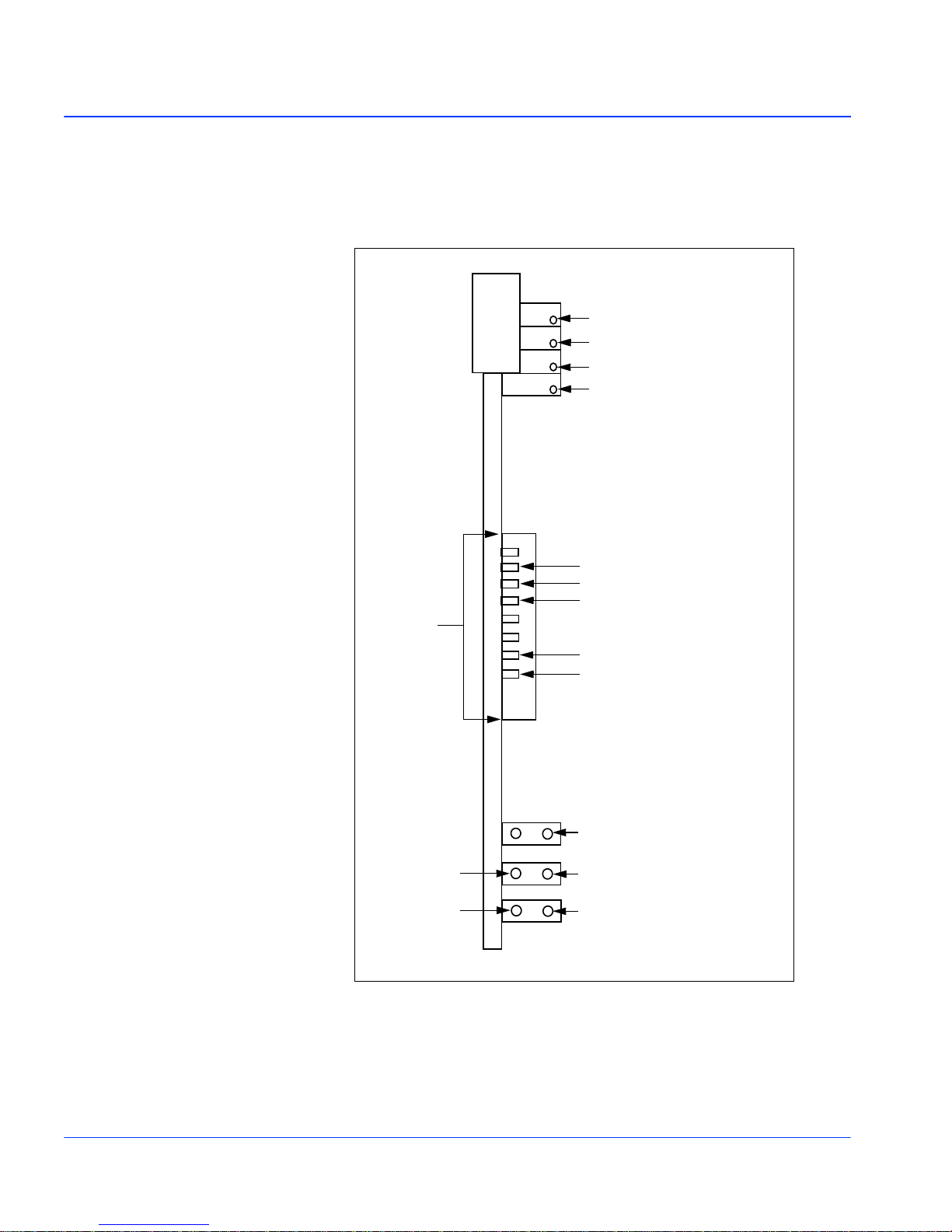
Figure 1-1 shows the side view of the DEC-6001:
DEC
6001N
Switch SW3
Video Gain
Chroma Gain
Black Level
NTSC Hue
(DEC-6001N/N only)
Pass VITS/Blanks VITS
Valid Black/Kill TRS on loss of input
Pedestal on/off (DEC-6001N/N only)
Coherent/Non Coherent
Cal/Adj
Coherent
Not Detent
+5V
No I/P
+ 12V
Figure 1-1. Side View of the DEC-6001
2 DEC-6001 User Manual
Page 23
Top View
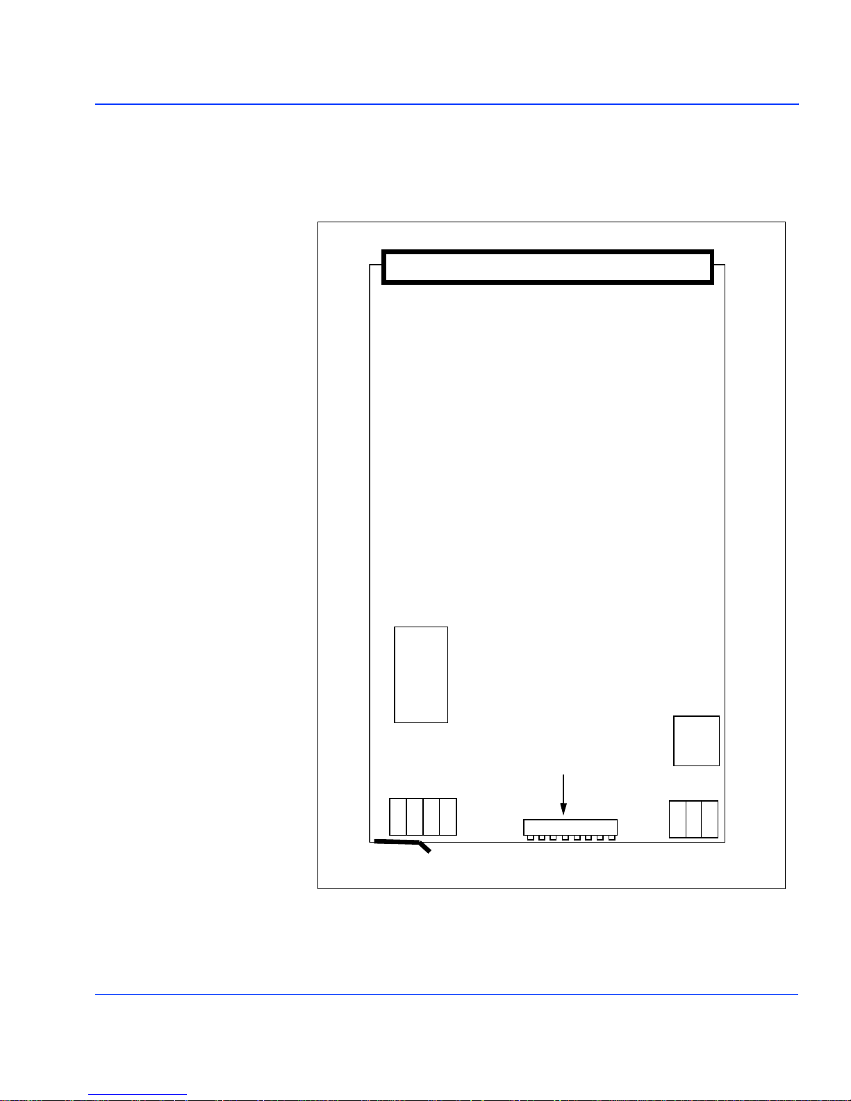
Figure 1-2 shows the top view of the DEC-6001:
IC 7
IC 34
Switch SW3
Figure 1-2. To p View o f t he DE C-60 01
DEC-6001 User Manual 3
Page 24

4 DEC-6001 User Manual
Page 25
Rear Connectors
The DEC-6001 is for use with Leitch Genesis FR-6001, FR-6002 and FR6004 frames.
This equipment may be damaged
by electrostatic discharge (ESD).
Suitable precautions must be
observed to minimize the risk of
ESD induced damage.
This add on device, model
DEC-6001, is intended to be
installed in equipment in the field,
by the user, in the manufacturer's
defined operator access area.
Check the equipment operating/
installation instructions or
equipment manufacturer to verify
that your equipment is suitable
(including power consumption)
for user installed application
devices.
Rear connectors that cannot be used in the FR-6002 are marked to
indicate this fact. When used in an FR-6004 frame the rear connector
interconnections are as shown in the manual.
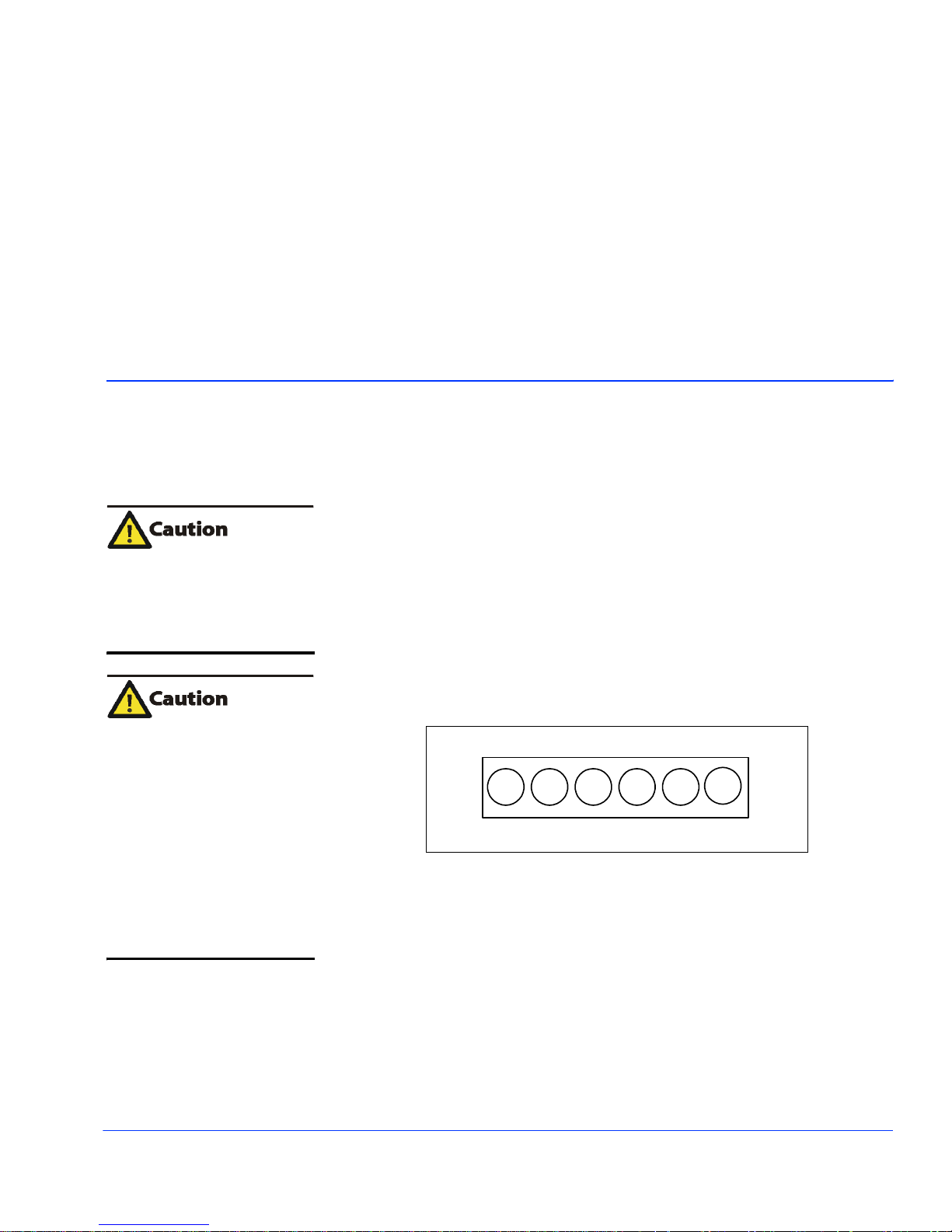
When used in a FR-6002 or FR-6001 frame, the rear connector is
mounted horizontally. Figure 2-1 shows the S6 rear connector mounted
horizontally with connector A becoming the left hand connector.
Installation
A
Figure 2-1. S6 Rear Connector Mounted Horizontally
C
B
E
D
F
Chapter 2
DEC-6001 User Manual 5
Page 26
S6 Rear Connector
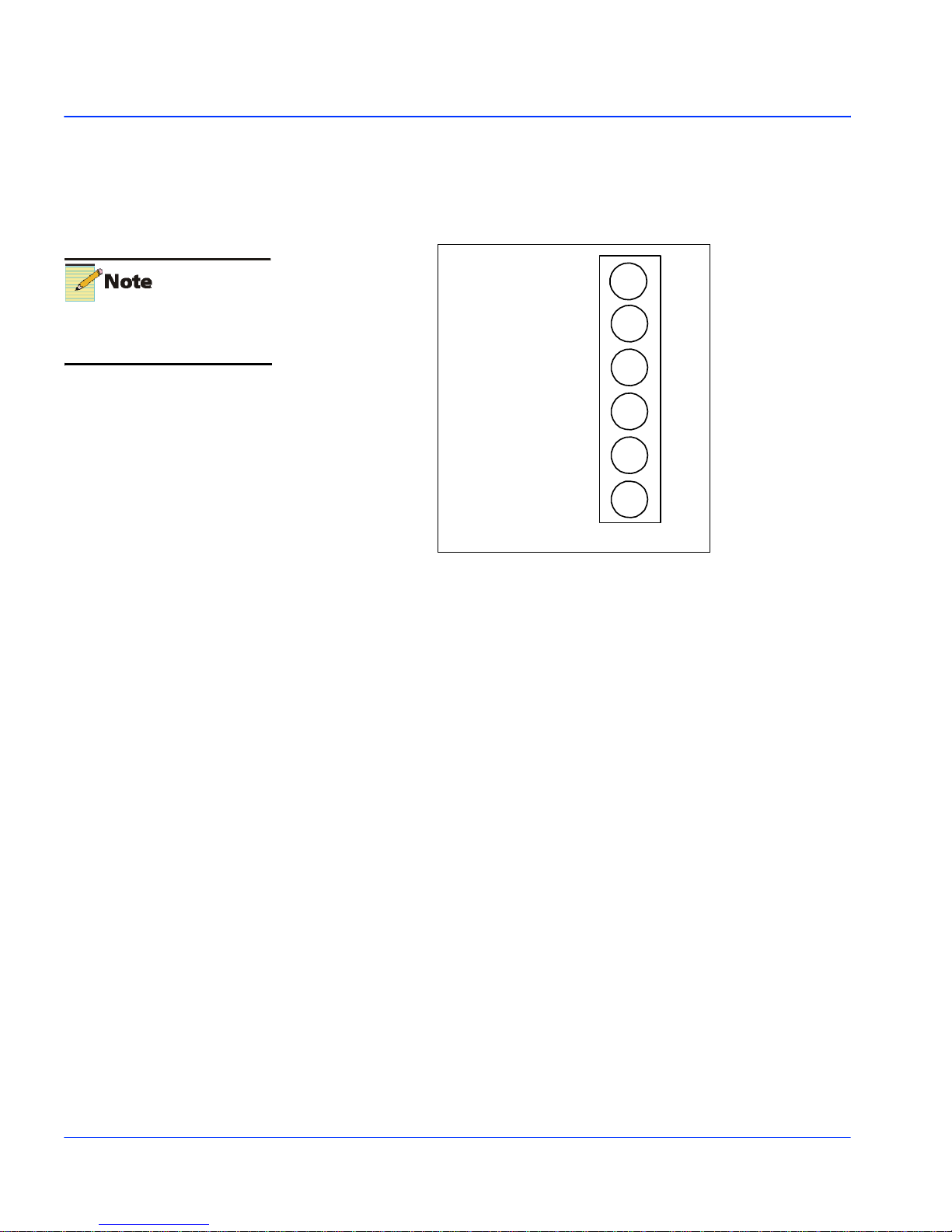
The S6 rear connector is used only with the DEC-6001 modules.
Figure 2-2 shows the S6 rear connections.
If the looping analog output is not
utilized, then a 75 W termination
must be fitted to BNC E.
Analog Input
Serial Digital Output
Serial Digital Output
Serial Digital Output
Serial Digital Output
Serial Digital Output
(270 Mb/s)
See note
(270 Mb/s)
(270 Mb/s)
(270 Mb/s)
(270 Mb/s)
F
E
D
C
B
A
Figure 2-2. S6 Rear Connector
6 DEC-6001 User Manual
Page 27
Setting the Switches
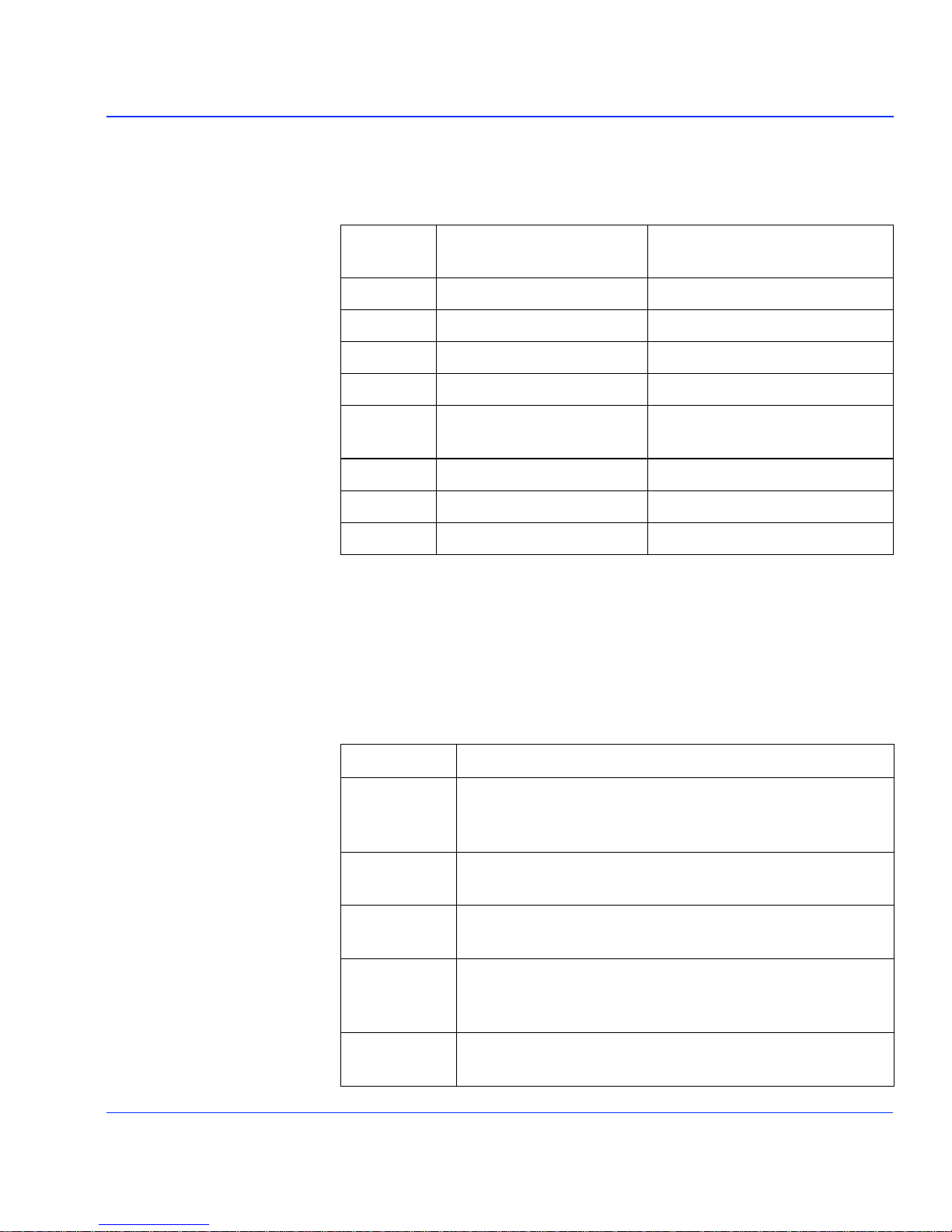
The following table lists the switch settings for the DEC-6001:
Switch
No SW3
8 Enable Proc Amp Adjust Factory Preset Levels
7 Non-Coherent Input Coherent Input
6
5
4 Input has no Pedestal
3 Kill TRS on Loss of Input Enable TRS on Loss of Input
2 VBI Blanked VBI Passed
1
Front Switches (SW3)
Where possible, the up state (away from PCB surface) is intended to be
the default and the down state (towards PCB surface) is the less often
used state. All switches relate to SW3 on the front of the
DEC-6001 board.
On
(towards PCB surface)
(DEC-6001N only)
Off
(away from PCB surface)
Input has Pedestal
(DEC-6001N only)
The following tables lists the switch functions of the DEC-6001:
Switch No. Function
Selects between factory calibrated levels (on) and user
8
7
4
3
2
DEC-6001 User Manual 7
adjustments (off) via the Proc amp potentiometers. It also
disables use of the potentiometers when in Cal mode.
Selects between non-coherent (off) and coherent (on)
standards.
When this switch is on, 525- line standards are assumed to
have no pedestal (DEC-6001N only).
Set this switch on to kill TRS on the output when there is no
input present. Set to off to enable TRS's on the output when
there is no input.
Set this switch on to blank VBI, and off to pass VBI. Passing
VBI is the normal mode.
Page 28

Potentiometer Adjustments
Potentiometers are labelled on the DEC-6001 board as Video gain,
Chroma gain, Black level, and NTSC hue. The potentiometers are
mounted on the top, front edge of the PCB.
The following table lists and describes the potentiometers of the DEC6001:
Potentiometer Description
Video Gain
Chroma Gain
Black Level
NTSC Hue
Adjusts the gain of the input with a range of zero to
double (+6 dB) gain.
Adjusts the gain of the input with a range of zero to
double (+6 dB) gain.
Shifts the input with a range of -100 mV to +100 mV.
In the NTSC standard only, allows the chroma phase to
be adjusted up to 90
(DEC-6001N only)
° either side of normal.
8 DEC-6001 User Manual
Page 29

Mechanical
Chapter 3
Specifications
The following table lists the mechanical specifications for the
DEC-6001:
Item Specification
Length 8.66 in. (220 mm)
Width 3.94 in. (100 mm)
Height 0.71 in. (18 mm)
Weight 8.82 oz. (250 g)
DEC-6001 User Manual 9
Page 30
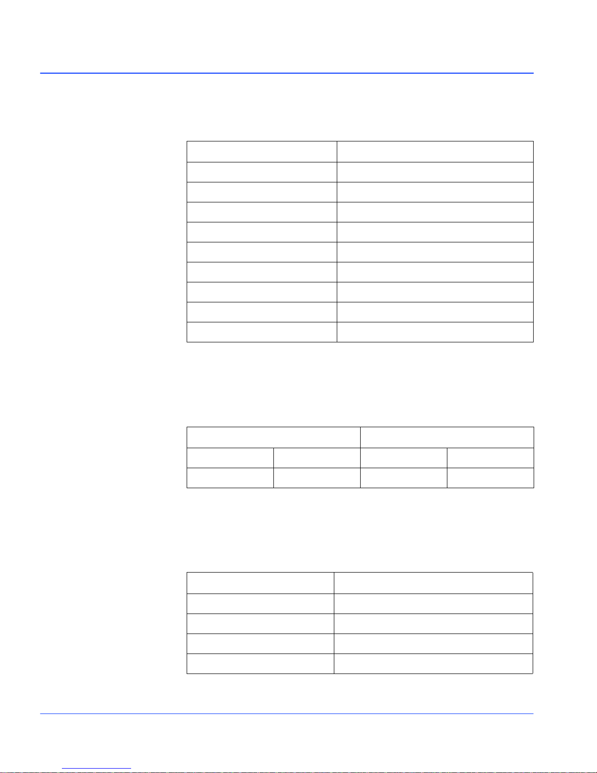
Electrical
The following table lists the electrical specifications for the DEC-6001:
Item Specification
Power Consumption 11.7 W (1.8A @ 6.5V)
Delay 70 µs
Frequency Response ±0.1dB to 5.5 MHz
Return Loss >40 dB
Subcarrier Rejection >50 dB
Transient Response <0.2% K rating
Differential Phase Error <1
Differential Gain Error <1%
Chroma-luma Delay Inequality <2 ns
VBI Handling
The following table lists the VBI handling specifications for the
DEC-6001:
1st Active Line Last Active Line
625 525 625 525
6/319 10/273 310/623 263/525
Process Control
The following table lists the specifications for process control adjustment
range for the DEC-6001:
°
Item Specification
Video Gain ±6 dB
Chroma Gain ±6 dB
Black Level ±100 mV
NTSC Hue ±90
10 DEC-6001 User Manual
°
Page 31

Appendix A
Edge Connections
The following table lists the edge connections for the DEC-6001:
Pin
Row A
1Analog I/P 1Ground
2 2
3 3
4 4
5 Looping Analog O/P 5 Ground
6 6
7 7
8 8
9Serial O/P 9Ground
10 10
11 11
12 12
13 13
Function
Pin
Row B
Function
DEC-6001 User Manual 11
14 14
15 -7.5V 15 -7.5V
16 Ground 16 Ground
17 +6.5V 17 +6.5V
Page 32
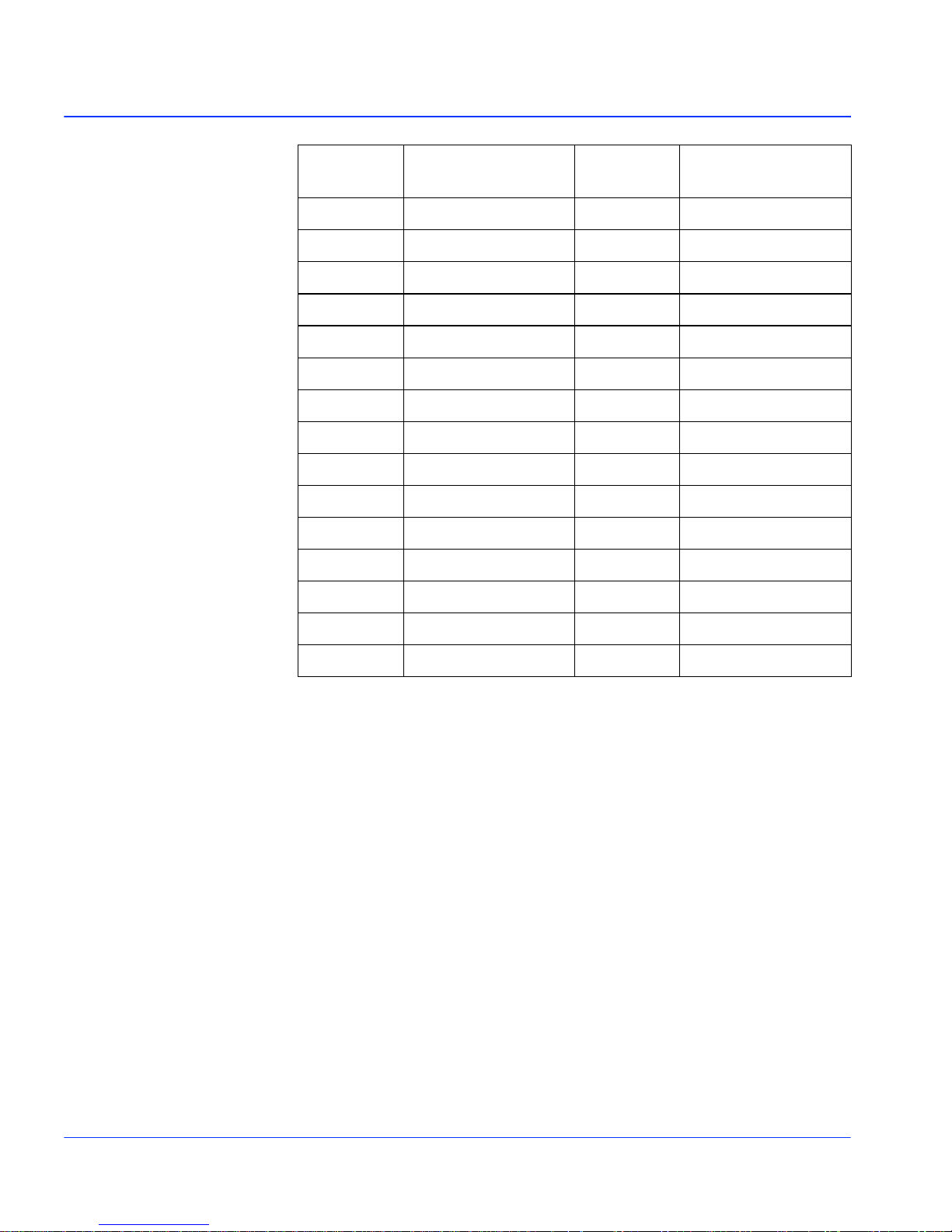
Pin
Row A
18 18
19 BO/S Flag 19 O/S PCB Sel
20 20
21 21
22 22
23 23
24 Serial O/P 24 Ground
25 COM1 A 25 COM1 B
26 COM2 A 26 COM2 B
27 27
28 Serial O/P 28 Ground
29 TKN Data 29 I2 Add
30 TKN Clock 30 I2 Ret
Function
Pin
Row B
Function
31 31
32 Serial O/P 32 Ground
12 DEC-6001 User Manual
Page 33

Warranty
Leitch Incorporated ("Leitch") warrants to each original end-user purchaser or
licensee (each, a "Customer") of hardware or software products manufactured by
Leitch (each, a "Product"), or of non-warranty repair or other services provided
by Leitch ("Services"), that each such Product and all such Services will be free
from defects in materials and workmanship that adversely affect the Product's
performance or the Services' intended purpose for a period (the "Warranty
Period") of:
l
One year for server hardware Products;
l
Two years for non-server, and Desktop hardware Products;
l
Ninety days for parts, assemblies and supplies to support hardware Products
previously sold to Customers;
l
Ninety days for media of software licensed separately from Leitch hardware
Products, and encoding created by Leitch as physically affixed on or
embedded in such media;
l
The same period as the hardware Product warranty for media of software
licensed as an integral part of any Leitch hardware Product, and encoding
created by Leitch as physically affixed on or embedded in such media
l
Ninety days for Services.
Please refer to the current "Leitch Limited Warranty Policy" for a complete
description of the warranty provided, including important exclusions and
limitations as well as procedures for obtaining warranty service.
Page 34

 Loading...