

Leisure Craft AMP-2.4 Service manual

Index
2
Technical Specifications, Introduction, Test Procedures & Adjustments
4
Schematic Diagrams
5
Layout & Spare Part List
SERVICE MANUAL
Warnings
Notice
Service must be carried out by qualified personnel only.Any tampering carried out by unqualified personnel during the guarantee period
will forfeit the right to guarantee.
For a correct operation of the instrument, after having switched off, be careful to wait at least 3 seconds before switching on again.
To improve the device's specifications, the schematic diagrams may be subject to change without prior notice.
All components marked by this symbol have special safety characteristics, when replacing any of these components use only
manufacturer's specified parts.
The (µ) micro symbol of capacitance value is substituted by U.
The (
) omega symbol of resistance value is substituted by E.
Ω
The electrolytic capacitors are 25Vdc rated voltage unless otherwise specified.
All resistors are 1/8
All switches shown in the "OFF" position. All DC voltages measured to ground with a voltmeter 20KOhm/V.
Soldering point.
Male connector.
Female connector.
M/F faston connector.
ATTENTION
Observe precautions when handling electrostatic sensitive devices.
Address
unless otherwise specified.
Ω
Supply voltage.
Test point.
Flag joined with one or more flags
with the same signal name inscribed.
Logic supply ground.
Analog supply ground.
Chassis ground.
Earth ground.
L
CODE: 270232
M
GENERALMUSIC S.p.A. Sales Division: 47842 S.Giovanni in Marignano (RN) ITALY - Via delle Rose, 12 - tel. 0541/959511 - fax 0541/957404
GENERALMUSIC on the NET: http://www.generalmusic.com
1 1
JJ
1
J
1 1
JJ
TECHNICAL SPECIFICATIONSTECHNICAL SPECIFICATIONS
TECHNICAL SPECIFICATIONS
TECHNICAL SPECIFICATIONSTECHNICAL SPECIFICATIONS
Dimensions: (WxHxD) 483x44x310mm (1U)
Weight: 8Kg
➭ Before proceed to supply the amplifier check visually the internal assem-
bly, if appears an evident damage find the most possible reasons that
cause it.
➭ Check the wiring cables for possible interruptions or shorts.
CN3 pin 3 =-15±1Vdc
➭ If one or more voltages don’t correspond, check the rectifiers, capacitors
and transformers disconnecting them from circuitry, refer to schematics.
Power Requirements: (230Vac±10% 50Hz) 300VA
Output Power: (8Ω stereo/parallel) 2x 130Watts
Max. Undistorted Out: (8Ω stereo/parallel) 92Vpp
Input Sensitivity: (constant sensitivity) 0.775Vrms (0dB)
Input Impedance: (balanced) 30KΩ
(unbalanced) 15KΩ
Voltage Gain: (constant sensitivity) 32±0.5dB
Slew Rate: 10V/µS
Damping Factor: (8Ω stereo/parallel) >400
Frequency Response (-0.2dB) 20Hz÷20KHz
at Full Power: (-3dB) 10Hz÷60KHz
IMD: (SMPTE 60Hz/7KHz 4:1) <0.1%
THD: (THD+N) <0.1%
S/N Ratio: (unweighted) >95dB
Crosstalk: (1KHz) >70dB
TEST PROCEDURES & ADJUSTMENTSTEST PROCEDURES & ADJUSTMENTS
TEST PROCEDURES & ADJUSTMENTS
TEST PROCEDURES & ADJUSTMENTSTEST PROCEDURES & ADJUSTMENTS
➭ If the damage has burnt a printed circuit board don’t try to repair it,
replace with a new one.
Test InstrumentsTest Instruments
Test Instruments
Test InstrumentsTest Instruments
➭ Audio Generator
➭ Dual Trace Oscilloscope
➭ Digital Multimeter
➭ 4Ω 500W, 8Ω 300W, 100Ω 10W resistors
➭ Variac (0÷250Vac)
SetupSetup
Setup
SetupSetup
➭ Connect the Variac between the mains and the amplifier and set it at zero
voltage.
➭ Set the amplifier in STEREO MODE and turn full clockwise the LEVEL
potentiometers.
➭ Connect the audio generator to the channel inputs and set it to 1KHz
775mV
➭ The procedures that follow must be executed subsequently in the order
specified.
(0dB) sinusoidal signal.
RMS
Channels CheckChannels Check
Channels Check
Channels CheckChannels Check
➭ The CH1 channel is on the left and CH2 channel is on the right of the
chassis.
➭ These procedures are intended for one channel at a time, repeat these
operation for the other channel.
➭ Verify, with the Multimeter, the insulation between the heatsink and the
transistors collectors.
➭ Verify, with the Multimeter, the PTC resistor value (R133 connected
across pin 8 an pin 9 of CN3), it must be between 50Ω and 200Ω.
SETUP:SETUP:
➭
SETUP:
SETUP:SETUP:
Connect the ch1 scope GND clip to CN102 pin 1 (GND terminal).
Connect the ch1 probe tip to CN102 pin 2 (AMP output).
Connect the ch2 probe tip to D109 anode and set it sensitivity at 5V/div.
Set the LEVEL potentiometers full clockwise.
The load resistor is disconnected.
INITIAL TEST:INITIAL TEST:
➭
INITIAL TEST:
INITIAL TEST:INITIAL TEST:
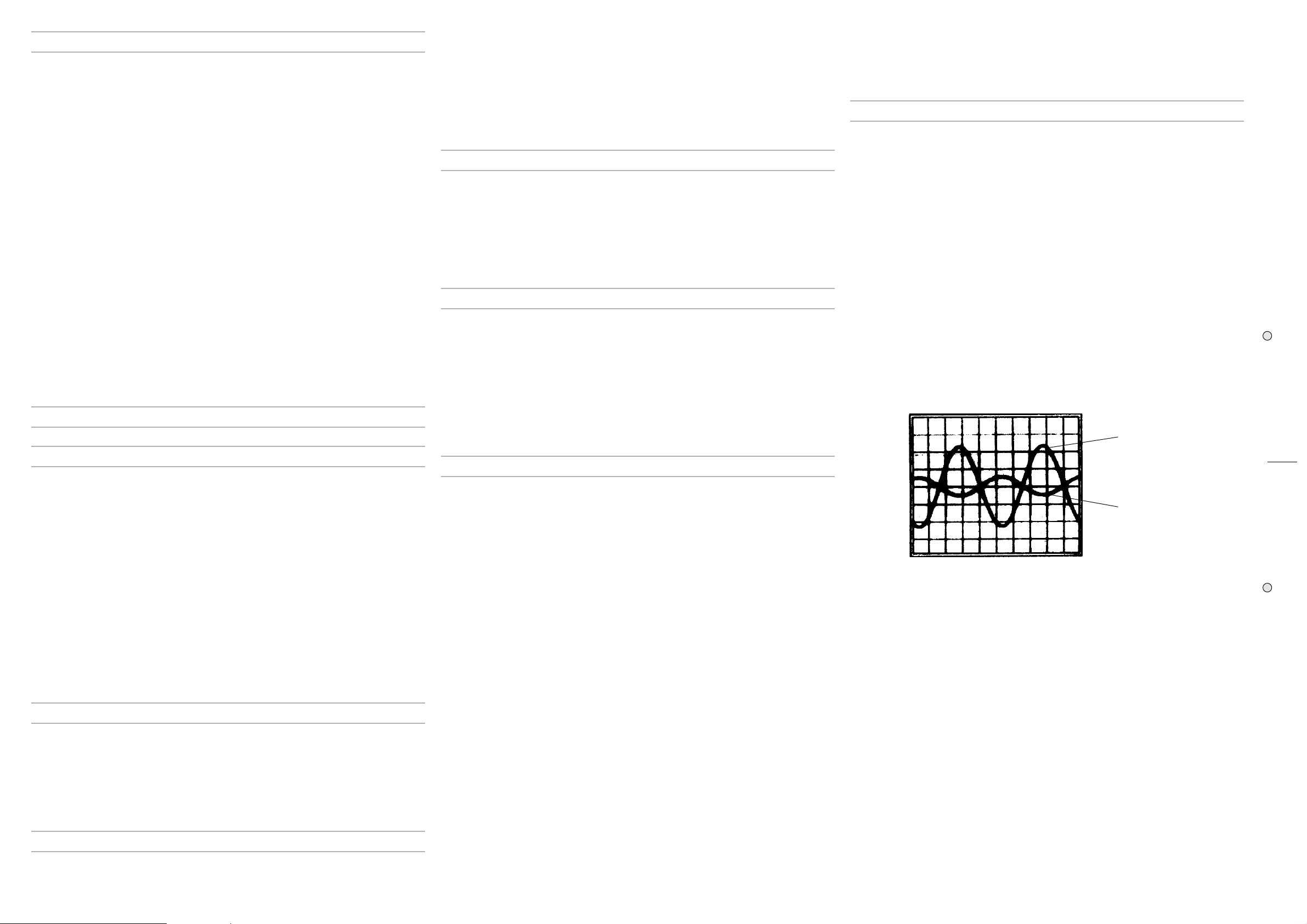
Increase slowly the Variac. The channel output signals must be symmetrical respect the GND without visible distortion and oscillation as shown in
Fig.1 Trace A (Trace B
distortion read the section ADVICES and proceed to check the other
Fig. 1Fig. 1
Fig. 1
Fig. 1Fig. 1
shown the amplifier 2nd stage input). If there is a
Trace A (20V/div.)
PrecautionPrecaution
Precaution
PrecautionPrecaution
➭ To prevent short circuit during any test,
EARTH insulatedEARTH insulated
EARTH insulated, this occurs because some test require to connect its
EARTH insulatedEARTH insulated
probe to the amplifier output, non-compliance may cause damages to
oscilloscope inputs circuitry.
➭ Before removing or installing any modules and connectors,
the amplifier from AC MAINSthe amplifier from AC MAINS
the amplifier from AC MAINS and measure the DC supply voltages
the amplifier from AC MAINSthe amplifier from AC MAINS
across each of the power suppliy capacitors. If your measurement on any
of the caps is greater than 10Vdc, connect a 100Ω 10W resistor across
the applicable caps to discharge them for your safety. Remember to
remove the discharge resistor immediately after discharging caps.
power up the amplifier with the discharge resistor connectedpower up the amplifier with the discharge resistor connected
power up the amplifier with the discharge resistor connected.
power up the amplifier with the discharge resistor connectedpower up the amplifier with the discharge resistor connected
➭ Read these notes entirely before proceeding to any operation. These
notes are not comprehensive of all damages that possibly occur, but
includes some specifically advices, checks and adjustments relative to
this amplifier.
RemarksRemarks
Remarks
RemarksRemarks
➭ The power supply utilizes a dual bipolar DC rail configuration with low and
high voltages; one positive and one negative low rail (+/-Vcc1) and one
positive and one negative high rail (+/-Vcc2).
➭ Some component references in the circuitry have the A letter suffix to
identify the CH1 channel and the B letter for CH2 channel.
Visual CheckVisual Check
Visual Check
Visual CheckVisual Check
➭ Use compressed air to clear dust in the amplifier chassis.
the oscilloscope must bethe oscilloscope must be
the oscilloscope must be
the oscilloscope must bethe oscilloscope must be
disconnectdisconnect
disconnect
disconnectdisconnect
Do notDo not
Do not
Do notDo not
Supply CheckSupply Check
Supply Check
Supply CheckSupply Check
➭ Remove the transformer secondary fuses (located on SUPPLY & PRO-
TECTIONS board), set the Variac to the nominal mains voltage, check
with the Multimeter the AC supply voltages:
FUSE1-FUSE2=55±1.5Vac
FUSE3-FUSE4=90±3Vac.
➭ Re-set the Variac at zero voltage, turn off the amplifier and put the fuses
back on its holders.
➭ Connect the oscilloscope probes ch1/2 to the channel outputs, before
RL1, set both to 20V/div. 200µS/div.
➭ Set up the Variac slowly monitoring the Outputs with the oscilloscope
ch1/2 connected, it should display the sinusoidal input signal amplified
with no distortions, if a distortion occur check the POWER AMPLIFIER
boards as suggested in the ADVICES section.
➭ If the protection trips, turn off the amplifier, wait some minutes and
disconnect the supplies from the outputs modules (CN1, CN4 on POWER
AMPLIFIER boards), continue to check the supplies.
CAUTION: Before re-connecting the output modules to the supplies,CAUTION: Before re-connecting the output modules to the supplies,
➭
CAUTION: Before re-connecting the output modules to the supplies,
CAUTION: Before re-connecting the output modules to the supplies,CAUTION: Before re-connecting the output modules to the supplies,
you must have the capacitors discharged for your safety: connect ayou must have the capacitors discharged for your safety: connect a
you must have the capacitors discharged for your safety: connect a
you must have the capacitors discharged for your safety: connect ayou must have the capacitors discharged for your safety: connect a
100100
ΩΩ
10W resistor across the caps and remove the resistor just after 10W resistor across the caps and remove the resistor just after
100
Ω
10W resistor across the caps and remove the resistor just after
100100
ΩΩ
10W resistor across the caps and remove the resistor just after 10W resistor across the caps and remove the resistor just after
they are discharged.they are discharged.
they are discharged.
they are discharged.they are discharged.
➭ Finally verify the DC supplies on POWER SUPPLIES board:
CN2-4 pin 3 (+Vcc2) =+61±2Vdc
CN2-4 pin 4 (+Vcc1) =+36±1.5Vdc
CN2-4 pin 2 (-Vcc1) =-36±1.5Vdc
CN2-4 pin 1 (-Vcc2) =-61±2Vdc
CN3 pin 5 =+15±1Vdc
Trace B (5V/div.)
channel.
BIAS ADJUSTMENT:BIAS ADJUSTMENT:
➭
BIAS ADJUSTMENT:
BIAS ADJUSTMENT:BIAS ADJUSTMENT:
Set the generator level at zero, connect the Multimeter across
and collector of TR108, then adjust R132 trimmer to read 2.5Vdc.
HIGH RAIL CHECK:HIGH RAIL CHECK:
➭
HIGH RAIL CHECK:
HIGH RAIL CHECK:HIGH RAIL CHECK:
Connect the ch2 probe tip to D103 cathode and set it sensitivity at 20V/
div.
When the output signal (Positive half-wave) is less than 30Vp the voltage
on D103 cathode must remain constant at 36V, when the output signal
exceeds 30Vp the voltage must follow the output signal with 6V offset
(see
Fig.2 Trace B
D114 anode (see
Connect the 8Ω 300W load on the output and repeat the INITIAL and
HIGH RAIL checks.
Check the signal clipping, it must occur at 48±2Vpp (see
A,B,C
).
SIGNAL/CLIP SENSOR CHECK:SIGNAL/CLIP SENSOR CHECK:
➭
SIGNAL/CLIP SENSOR CHECK:
SIGNAL/CLIP SENSOR CHECK:SIGNAL/CLIP SENSOR CHECK:
Set the LEVEL pot to minimum, set the scope timebase at 1V/div. 200µS/
div., then increase the level and check the SIGNAL/CLIP led activity: it
must turn on (green light) when the amplifier output is higher than 1Vp.
Set the scope at 20V/div. and increase the level, check the LIMITER led
), to check the negative high rail connect the probe to
Fig.2 Trace C
).
the emitter
Fig.3 Trace
J J
J
J J
22
2
22
 Loading...