

Leisure Signature Series, Sunlite Series, TP400, spaTouch, Paragon Series Owner's Manual
...
Read in conjunction with Part A – General Manual to
form a complete Owner’s Manual
LM-M-B-16
Signature Series
SPA OWNER’S MANUAL
IMPORTANT SAFETY INSTRUCTIONS
PART B – BRAND SPECIFIC MANUAL
ELECTRICAL CONNECTION
Sunlite Series
KEYPAD OPERATION
Paragon Series
Freestyle Series

2
Leisure Manufacturing 2016 Owner’s Manual
INDEX
Table of Contents
BRAND CONFIGURATION TABLE ................................................................................................................................................................ 3
ELECTRICAL CONNECTION - GENERAL INFORMATION............................................................................................................................... 4
LOCATING A CONDUIT WITHIN A CONCRETE PAD ............................................................................................................................... 4
SUPPLY CABLE ENTRY INTO SPA EQUIPMENT AREA ............................................................................................................................. 4
HOW TO PASS THE CABLE THROUGH THE SPA ENCLOSURE ................................................................................................................ 4
115 VOLT SUPPLY CONNECTION ........................................................................................................................................................... 5
CONVERTIBLE/MULTI VOLTAGE SUPPLY OPTION ................................................................................................................................. 6
230 VOLT SUPPLY CONNECTION ........................................................................................................................................................... 7
TYPICAL NORTH AMERICAN GROUND FAULT CIRCUIT INTERRUPTION (GFCI) ..................................................................................... 8
SPECIAL NOTE: DISCONNET SWITCH .................................................................................................................................................... 8
SPECIAL NOTE: EMERGENCY SWITCH ................................................................................................................................................... 8
YOUR FILTER – REMOVAL & REPLACEMENT .............................................................................................................................................. 9
ADDENDUM A – TP600 USER GUIDE W/ SIMPLIFIED MENUS ................................................................................................................. 13
ADDENDUM B – TP600 USER GUIDE W/ STANDARD MENUS .................................................................................................................. 28
ADDENDUM C – SPA TOUCH USER GUIDE ............................................................................................................................................... 53
DOC: LM-M-B-16

Leisure Manufacturing 2016 Owner’s Manual
3
BRAND CONFIGURATION TABLE
Series
Model
Frame/Bottom
Filter
User Guide
680 Polysteel/PE Whitewater TP600 Simplified
770/C107 Polysteel/PE Whitewater TP600 Simplified
780/C108 Polysteel/PE Whitewater TP600 Simplified
Signature/
Freestyle
Sunlite/
Freestyle
Sunlite Deluxe
939 Polysteel/PE Whitewater TP600 Simplified
949 Polysteel/PE Whitewater TP600 Simplified
959 Polysteel/PE Whitewater TP600 Simplified
989 Polysteel/PE Whitewater TP600 Simplified
S102/S200SE Polysteel/PE Teleweir TP600 Simplified
S103/S300SE Polysteel/ABS Pan Elite TP600 Simplified
S104/S400SE Polysteel/ABS Pan Elite TP600 Simplified
S105/S500SE Polysteel/ABS Pan Elite TP600 Simplified
S106/S600SE Polysteel/ABS Pan Elite TP600 Simplified
S103DLX Polysteel/ABS Pan Elite SpaTouch
S104DLX Polysteel/ABS Pan Elite SpaTouch
S105DLX Polysteel/ABS Pan Elite SpaTouch
S106DLX Polysteel/ABS Pan Elite SpaTouch
Jewel Steel/ABS Base Paragon XL SpaTouch
Legend Steel/ABS Base Paragon XL SpaTouch
Paragon
Essence Steel/ABS Base Paragon XL SpaTouch
Genesis Steel/ABS Base Paragon XL SpaTouch
Medallion Steel/ABS Base Paragon XL SpaTouch
Note: The factory default for spas using the TP600 keypad is Simplified Menus. However, more keypad
settings and features are possible on some spas by accessing the Standard menus within the spa pack. A
spa pack set up change is required to access these settings and features within the standard menus.
Ask your dealer about the set up change required.
When the spa has a circ pump or Microsilk option the spa pack changes and so does the default setting for
the keypad to Standard menus.
DOC: LM-M-B-16
4
Leisure Manufacturing 2016 Owner’s Manual
ELECTRICAL CONNECTION – GENERAL
INFORMATION
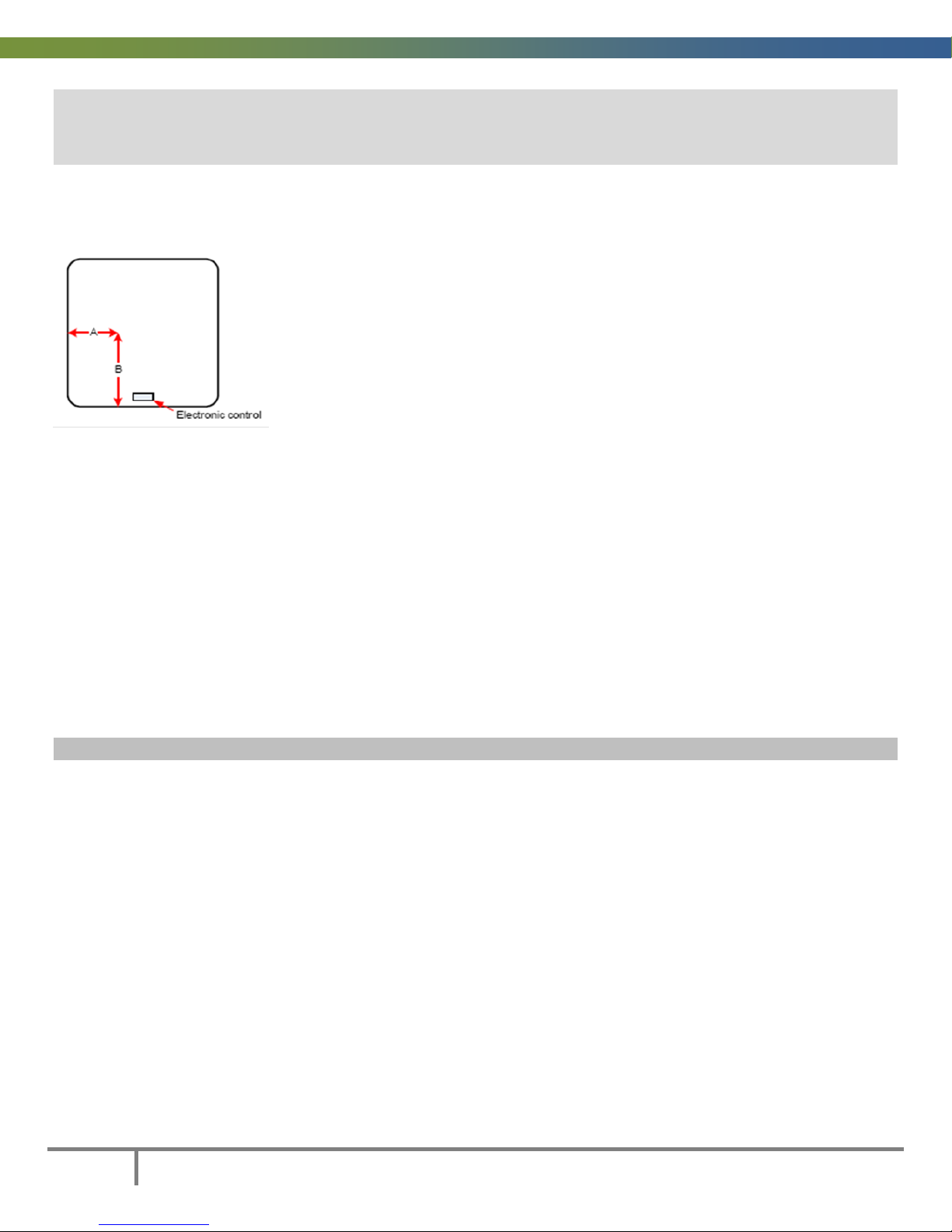
A. LOCATING A CONDUIT WITHIN A CONCRETE PAD
If your intent is to bring a conduit and power wires up under the spa we
suggest that it enter the spa cavity in the front, left corner; 6” (15cm)
Dimension A in from the left and 6” (15cm) Dimension B up from the front.
See A & B on the diagram below. This location will allow you to stay clear of
spa pumps and other equipment while giving you a short and easy access to
the left side of the spa pack, where the electrical entry hole an d terminal
block are located.
B. SUPPLY CABLE ENTRY INTO SPA EQUIPMENT AREA
• You may enter the spa cavity at any other point around spa provided you have reviewed the
location and determined there is no interference. You may also decide t o enter at an adjoining wall
(depending on the positioning of the spa) and route a conduit along the spa kicker. Ask your
electrician for his/her advice in these matters.
• In all cases the best side for entry of the supply cable is the side to your left when you are standing
at the equipment panel.
• Right side entry is possible; however, this may involve additional supply cable, parts and time.
HOW TO PASS THE CABLE THROUGH THE SPA ENCLOSURE
POLYSTEEL FRAME WITH POLYETHYLENE BOTTOM AND POLYSTEEL PANELS
a) You can choose to notch the polysteel panel so you can pass the cable/conduit through and still be
able to remove/replace the panel for servicing. You should consider securing the cable or conduit to
the spa’s metal frame where cable/conduit passes through the cabinet.
b) You may also route a cable up under the corner. The curved panel is flexible enough and there is
enough space to run the cable this way. Removing the corner may help you to do this easier.
c) On a concrete pad where you have a conduit or cable coming up within the perimeter of the spa,
you can easily cut an opening in the polyethylene bottom to access the cable or conduit/wires. See
above table for recommended opening location.
You may wish to insulate any opening or cut-out you make in the spa’s cabinet panel or corner or bottom
to keep cold air and small animals out.
DOC: LM-M-B-16
Leisure Manufacturing 2016 Owner’s Manual
5
115 VOLT CORD CONNECTION
This unit has been built, tested and approved with a cord connected 115VAC built in Ground Fault Circuit
Interrupter (GFCI).
The cord must only be plugged into a receptacle that is connected to
a dedicated 15A breaker or fuse.
DO NOT extend the connection by the use of an extension cord. This
will void the warranty and could cause damage to the spa and its’
users.
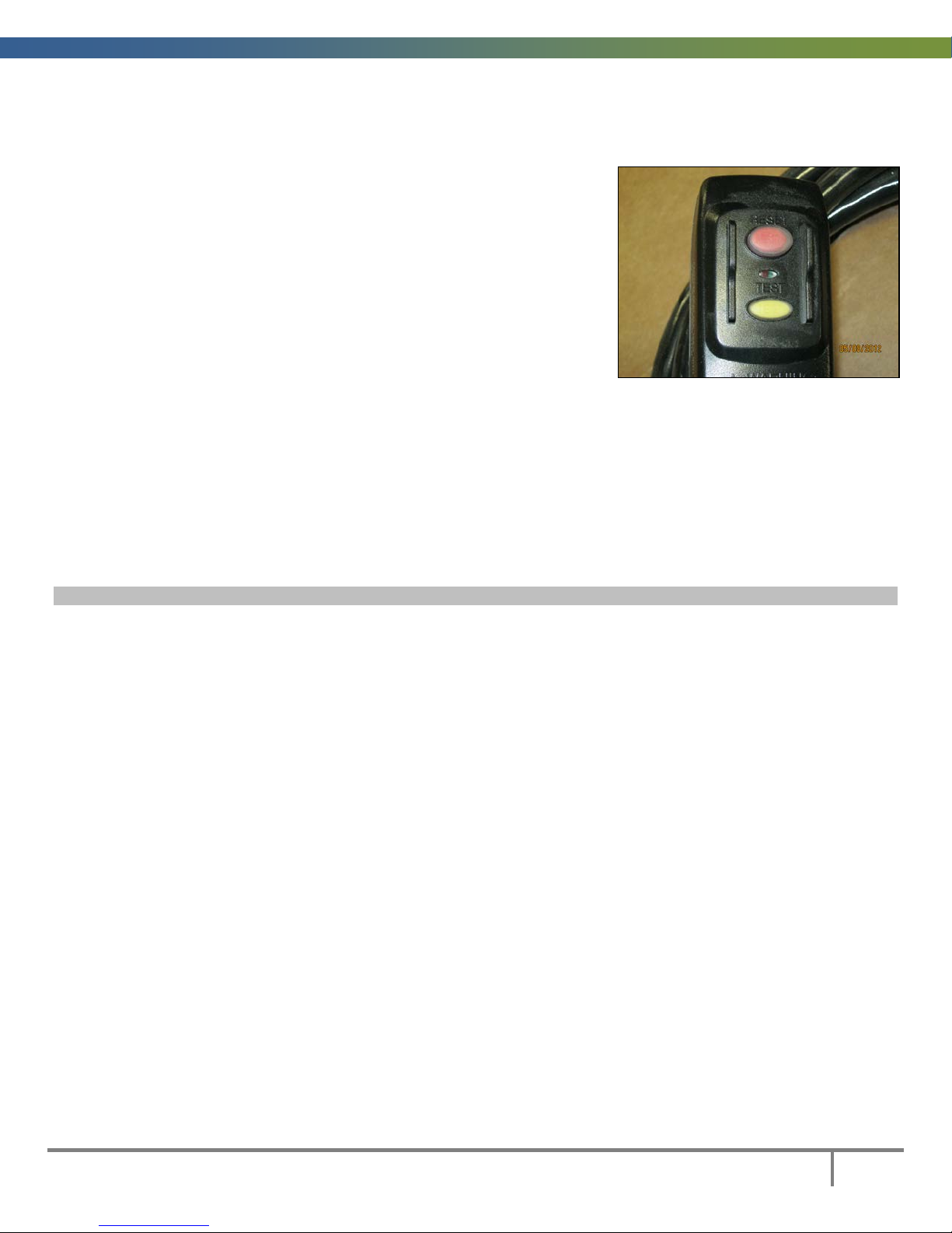
GFCI Test Procedure:
1. With the GFCI plugged into a grounded 115VAC, 15A outlet
press the yellow TEST button.
2. The spa should shut off and a small light between the TEST
and RESET buttons should be lighted.
3. Press the red RESET button to reset the GFCI and start the spa.
FAMILIARIZE yourself with the test procedure for the GF CI. TEST the GFCI upon every use of the spa.
If the GFCI does not shut the spa off when the TEST button is pressed or does not start up when the
RESET button is pressed DO NOT USE THE SPA. Contact your dealer and/or a qualified electrician
immediately. Take steps to ensure that no person(s) can use the spa while the problem is being reviewed
and corrected.
Note: In new installations, GFCI trippings due to mis-wiring are very common.
If the breaker is properly wired, GFCI trippings can occur when the total amount of current drawn by the
spa exceeds the rating of the breaker. Such an occurrence, however, is very unlikely, since each output of
the spa pack is individually fused and fuses will blow before the GFCI trips. A current leak to the ground
will also make the GFCI trip. If one or more of the components is faulty and there is a leak of more than 5
mA, the GFCI will trip to prevent electrocution.
DOC: LM-M-B-16
6
Leisure Manufacturing 2016 Owner’s Manual
Jumper (step 3)
Dip Switches
Cord and Plug Connected – Convertible Units
This spa was factory made as a 120 VAC spa with corded GFCI. Its’ power input can be converted to a 120
or 240VAC permanent connection. This must be done by employing a qualified electrician and in
accordance with local electrical codes.
CAUTION:
Connect only to a circuit protected by a Class A Ground Fault Circuit Interrupter
when converting to the permanent connection mode.
To convert from the factory 120VAC cord connected GFCI to 120 or 240VAC permanent connection follow
these instructions:
1. Remove the 120VAC cord with GFCI at the terminal block and ground bar. ( 3 connection points)
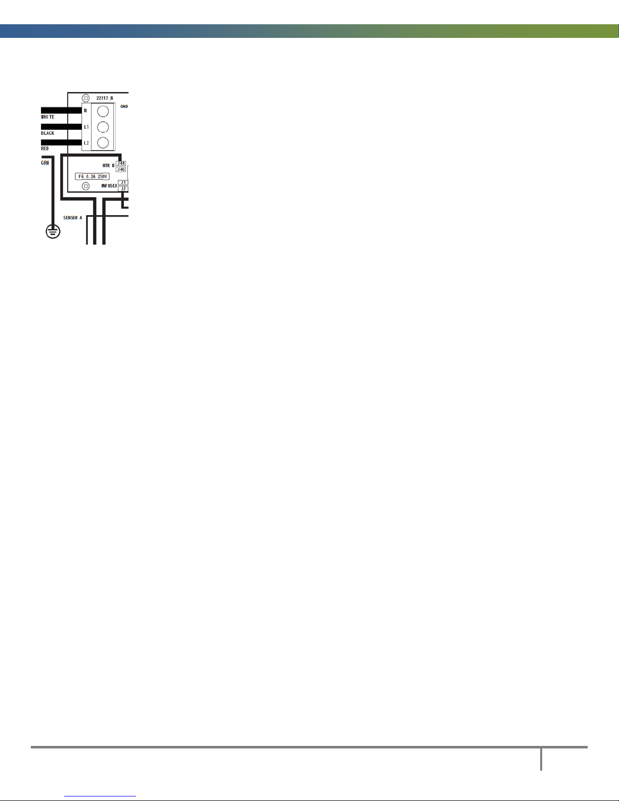
2. A) to connect a 120VAC permanent supply from a class A GFCI:
Connect White (Neutral/N), Black (Hot/L1) and Green (ground wire/GRN) to the input terminal
block as shown on the wiring diagram inside the spa pack cover. See the spa ratings label for
current, wire size and breaker requirements.
B) to connect to a 240VAC permanent supply from a class A GFCI:
Connect White (Neutral/N), Black (Hot/L1), Red (Hot/L2) and Green (ground wire/GRN) to the
input terminal block as shown on the wiring diagram inside the spa pack cover. See the spa ratings
label for current, wire size and breaker requirements.
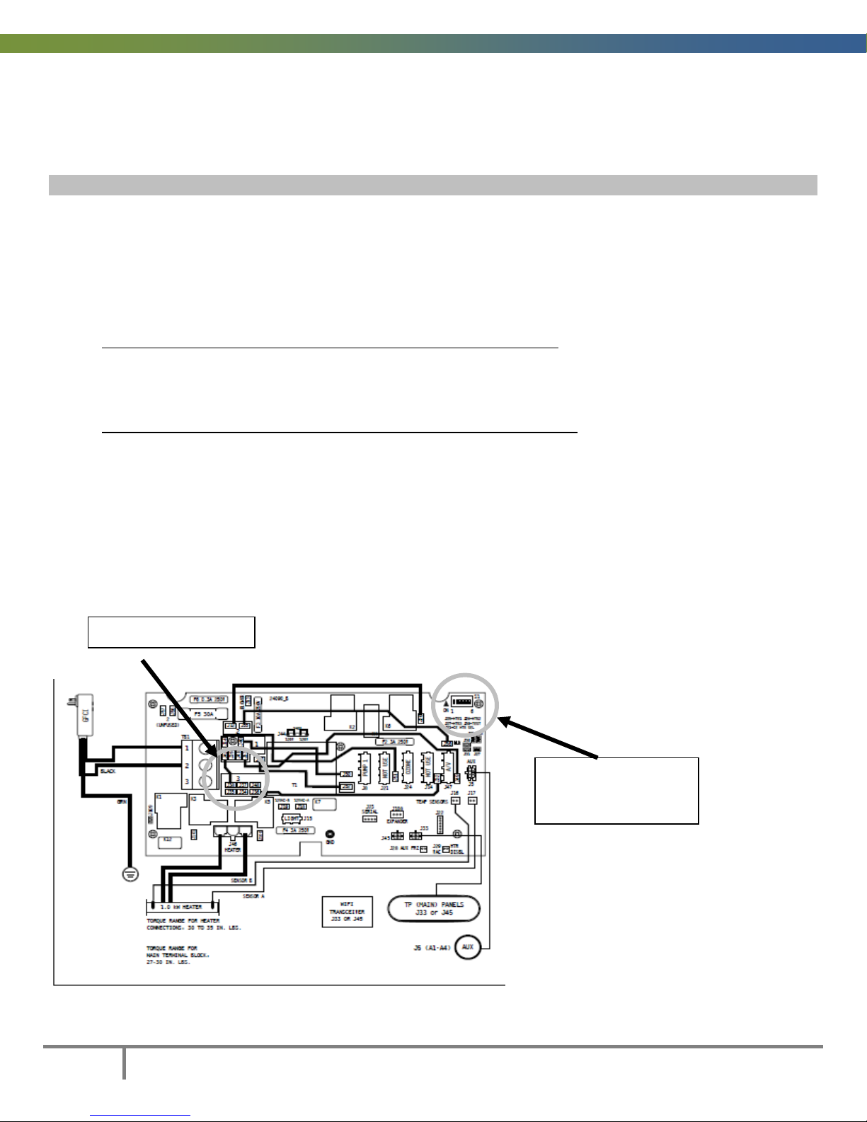
Steps 3, 4 & 5 apply only to a 240VAC permanent connection.
3. Remove the white jumper wire connecting J42 on the WHT AC bank (area 1) to J38 on the RED AC
bank (area 3). See diagram below.
4. Before powering up the spa, locate the dipswitch bank in the top, right corner of the circuit board.
5. Locate dipswitch #2 and move it to the ON position (UP).
(steps 4 & 5)
DOC: LM-M-B-16
Leisure Manufacturing 2016 Owner’s Manual
7
230 VOLT SUPPLY CONNECTION
Power Requirements
240VAC, 60Hz, Class A GFCI-protected service
4 wires (Hot-Line 1, Hot-Line 2, Neutral, Ground)
For current requirements & breaker rating see nameplate on spa.
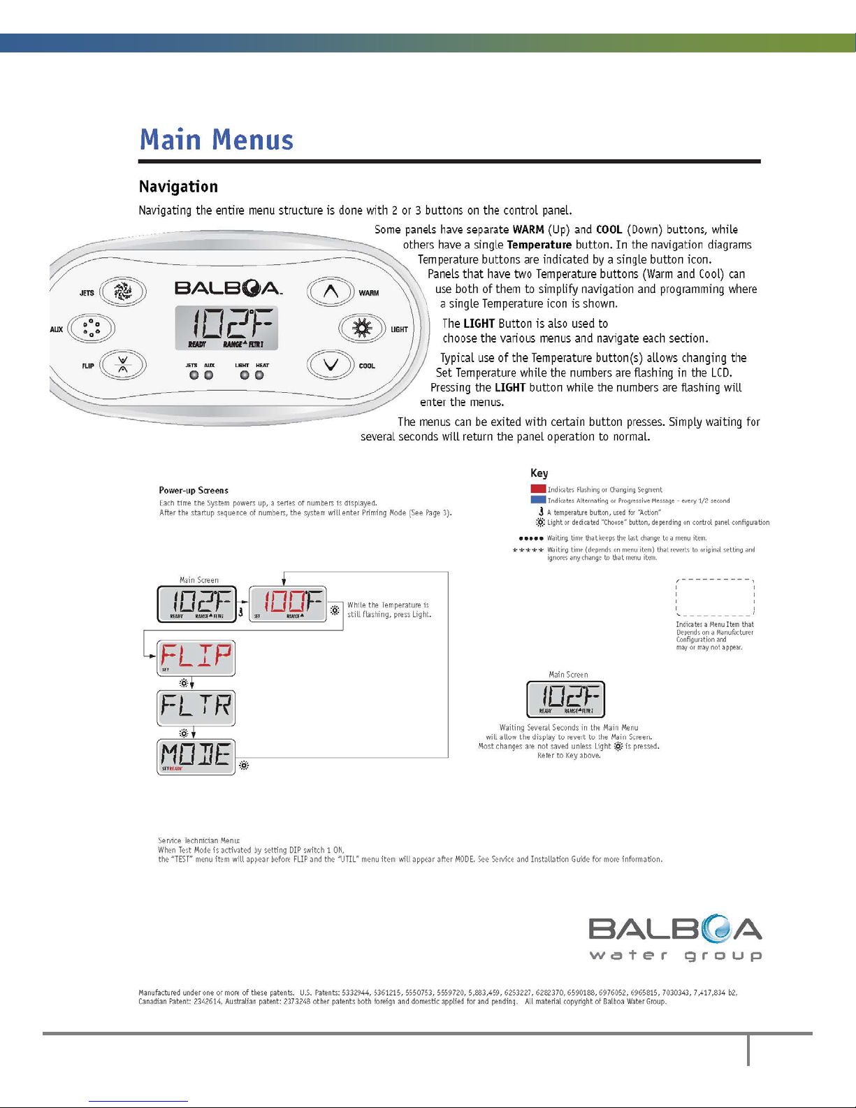
Power Up Screen
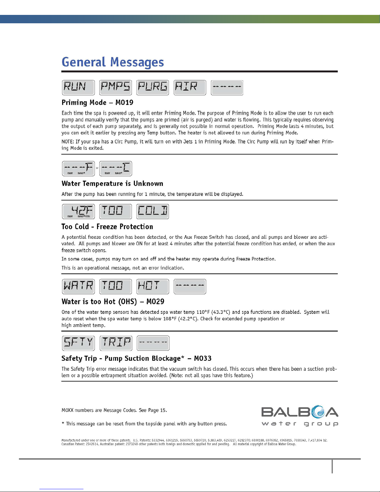
Each time the system powers up, a series of numbers is displayed. After the start-up sequence of
numbers, the system will enter Priming Mode. Next, refer to the User Guide for your keypad at the back of
this manual.
NORTH AMERICAN (60HZ) MODELS
Please note the following important information:
When using this electrical equipment, basic safety instructions should be followed, including the following:
READ AND FOLLOW ALL DIRECTIONS
1) Electrical installation must be carried out by a qualified electrician strictly in accordance with local
governing codes.
2) A terminal marked "ground" is located within the control box. To reduce the risk of electric shock
this terminal must be connected to the grounding means provided in the electric supply service
panel with a continuous copper wire equivalent in size to the circuit conductors supplying the
equipment.
3) At least two lugs marked "bonding lugs" are provided on the external surface of the control box. To
reduce the risk of electric shock connect the local common bonding grid in the area of the hot tub
or spa to these terminals with an insulated or bare copper conductor not smaller than No. 6 AWG.
4) All field installed metal components such as rails, ladders, drains or other similar hardware within
3m (10 ft.) of the spa or hot tub shall be bonded to the equipment grounding bus with copper
conductors not smaller than No. 6 AWG.
5) Test the ground fault circuit interrupter before each use of the spa.
6) Before servicing any electrical components of the system make sure that the power supply is
switched off.
DOC: LM-M-B-16
8
Leisure Manufacturing 2016 Owner’s Manual
Amp rating of spa
Supply Wire type and size
Over Current
More than
To
60C copper, AWG
75C copper, AWG
16
20
10
10
25
20
24
10
10
30
24
28 8 10
35
28
32
8 8 40
32
36
6 8 45
36
40
6 8 50
40
48
4 6 60
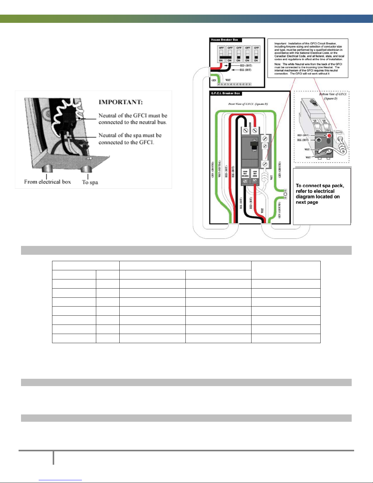
TYPICAL NORTH AMERICAN GFCI
Several different models of GFCIs are available on the market.
Note that our illustrations are generic.
WIRE SIZE AND OVER CURRENT PROTECTION (CANADA/US)
Protection (amps)
Note: If your GFCI trips immediately on start-up or during the opening use of the spa, DO NOT USE THE
SPA and take precautions to ensure that no one uses the spa, while you contact your dealer/electrician.
GFCI trips on newly installed spas are predominantly caused by mis-wired GFCIs.
SPECIAL NOTE: DISCONNECT SWITCH
This unit must be connected to a disconnect that de-energizes power to the entire unit for servicing,
maintenance or the like. The disconnect switch, with marked "OFF" position, must be located within sight
from the equipment and at least 5ft. (1.52m) from the inside walls of the spa .
SPECIAL NOTE: EMERGENCY SWITCH
This unit is intended for use in a single family dwelling. When used in locations other than a single family
dwelling, a clearly labelled emergency switch, readily accessible to the occupants and at least 5ft. (1.52m)
away from the unit, shall be provided as part of the installation.
DOC: LM-M-B-16
Leisure Manufacturing 2016 Owner’s Manual
9
YOUR FILTER – REMOVAL & REPLACEMENT
1. Shut off your spa at the Ground Fault Circuit
1. Shut off your spa at the Ground Fault Circuit
Our various spa models use different filter systems depending on the spa design. Identify which filter
system is in your spa and check (√) it off for future reference.
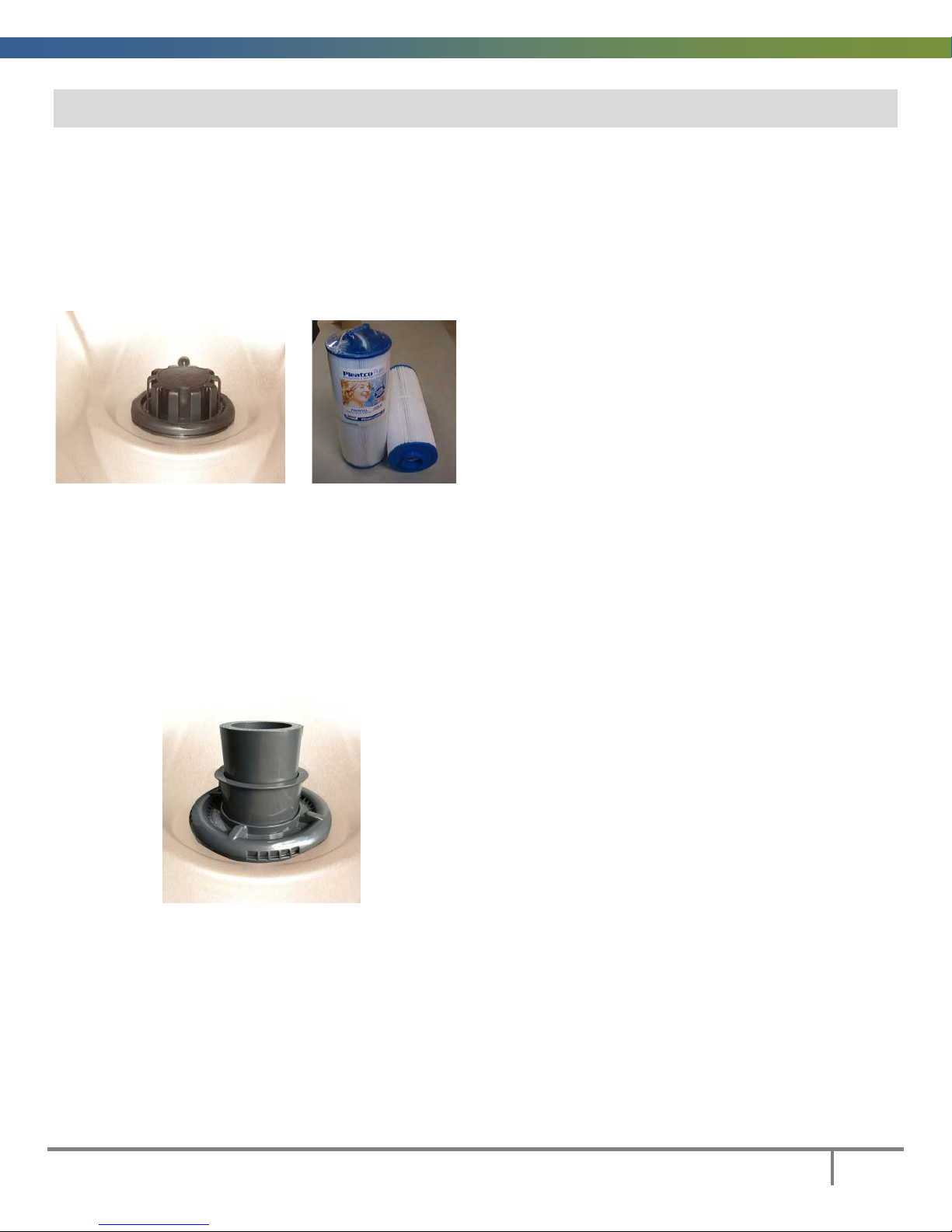
“TELEWEIR” SKIM FILTER
Single cartridge mounted vertically 50 sq ft, 14 ½” (36.8cm) high (part #PWW50L)
Interrupter (GFCI) or Residual Current
Detector (RCD).
2. Lift the floating weir and filter sleeve straight
up above the filter body to remove.
3. Use the c artridge h a ndle to thread the
cartridge out of the filter body.
4. Examine, clean, rotate or replace the
cartridge as necessary.
5. Hold the filter sleeve and twist w eir top to
remove weir and allow basket debris to be
dumped out.
6. Reverse the procedure to install new or
cleaned cartridges.
ELITE TELESCOPING WEIR FILTER
Single cartridge, vertically mounted, 75 sq. ft. 14 13/16”(37.6cm) high (part #PLBS75)
Interrupter(GFCI) or Residual Current
Detector(RCD)
2. Use the raised tabs on the outer ring to turn
the ring and 2 piece weir assembly counter
clockwise until it relea ses form the filter
body. Remove and set aside.
3. Remove the debris basket by grasping the
inner tab. Dump any debris and set aside.
4. Pull cartridge straight up and out of the filter
body.
5. Examine, clean, rotate or replace the
cartridge as necessary.
6. Reverse the procedure to install new or
cleaned cartridge.
DOC: LM-M-B-16
10
Leisure Manufacturing 2016 Owner’s Manual
1) Shut off your spa at the Ground Fault Circuit
1) Shut off your spa at the Ground Fault Circuit
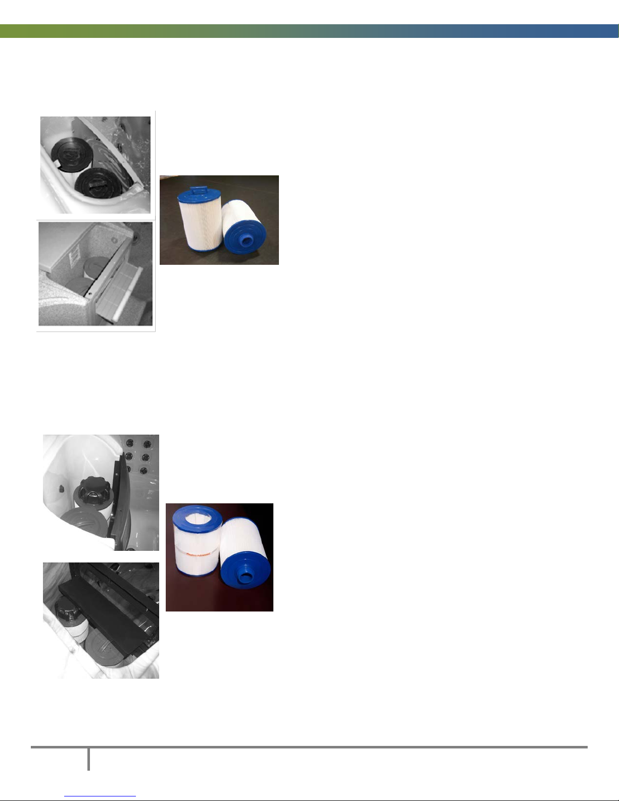
WHITEWATER SKIM FILTER
Dual cartridges mounted vertically 50 sq. ft. each, 8” (20cm) high (part #PPG-50P4)
Interrupter (GFCI) or Residual Current
Detector (RCD).
2) Remove the decorative top cover.
3) Remove each cartridge by simply grasping
the handle and turning it until it threads out
of the cartridge mount.
4) Reverse the procedure to install new or
cleaned cartridges.
WHITEWATER SKIM FILTER – SPLIT VERSION
Dual cartridges mounted vertically – 1 at 50 sq. ft. 8”(20cm) high (Part # PPG50-P4)
– 1 at 35 sq. ft. coreless, 7¼”(18.4cm) high (Part # PSN35)
Interrupter (GFCI) or Residual Current
Detector (RCD).
2) Remove the decorative top cov er.
3) Remove the 50 sq. ft. cartridge by using its
top handle to thread the cartridge off its
mount.
4) Remove the 35 sq. ft. coreless cartridge by
threading the large nut off the permanent
core. Then lift the cartridge up to remove it.
5) Reverse the procedure to install new or
cleaned cartridges.
DOC: LM-M-B-16

Leisure Manufacturing 2016 Owner’s Manual
11
DOC: LM-M-B-16
12
Leisure Manufacturing 2016 Owner’s Manual
DOC: LM-M-B-16

Leisure Manufacturing 2016 Owner’s Manual
13
ADDENDUM A
TP600 User Guide
With Simplified Menu Feature
DOC: LM-M-B-16

14
Leisure Manufacturing 2016 Owner’s Manual
DOC: LM-M-B-16
Leisure Manufacturing 2016 Owner’s Manual
15
DOC: LM-M-B-16
16
Leisure Manufacturing 2016 Owner’s Manual
DOC: LM-M-B-16
Leisure Manufacturing 2016 Owner’s Manual
17
DOC: LM-M-B-16

18
Leisure Manufacturing 2016 Owner’s Manual
DOC: LM-M-B-16

Leisure Manufacturing 2016 Owner’s Manual
19
DOC: LM-M-B-16
20
Leisure Manufacturing 2016 Owner’s Manual
DOC: LM-M-B-16
Leisure Manufacturing 2016 Owner’s Manual
21
DOC: LM-M-B-16
22
Leisure Manufacturing 2016 Owner’s Manual
DOC: LM-M-B-16
Leisure Manufacturing 2016 Owner’s Manual
23
DOC: LM-M-B-16
24
Leisure Manufacturing 2016 Owner’s Manual
DOC: LM-M-B-16
Leisure Manufacturing 2016 Owner’s Manual
25
DOC: LM-M-B-16
 Loading...