

Leisure L23, 23SL Owner's Manual
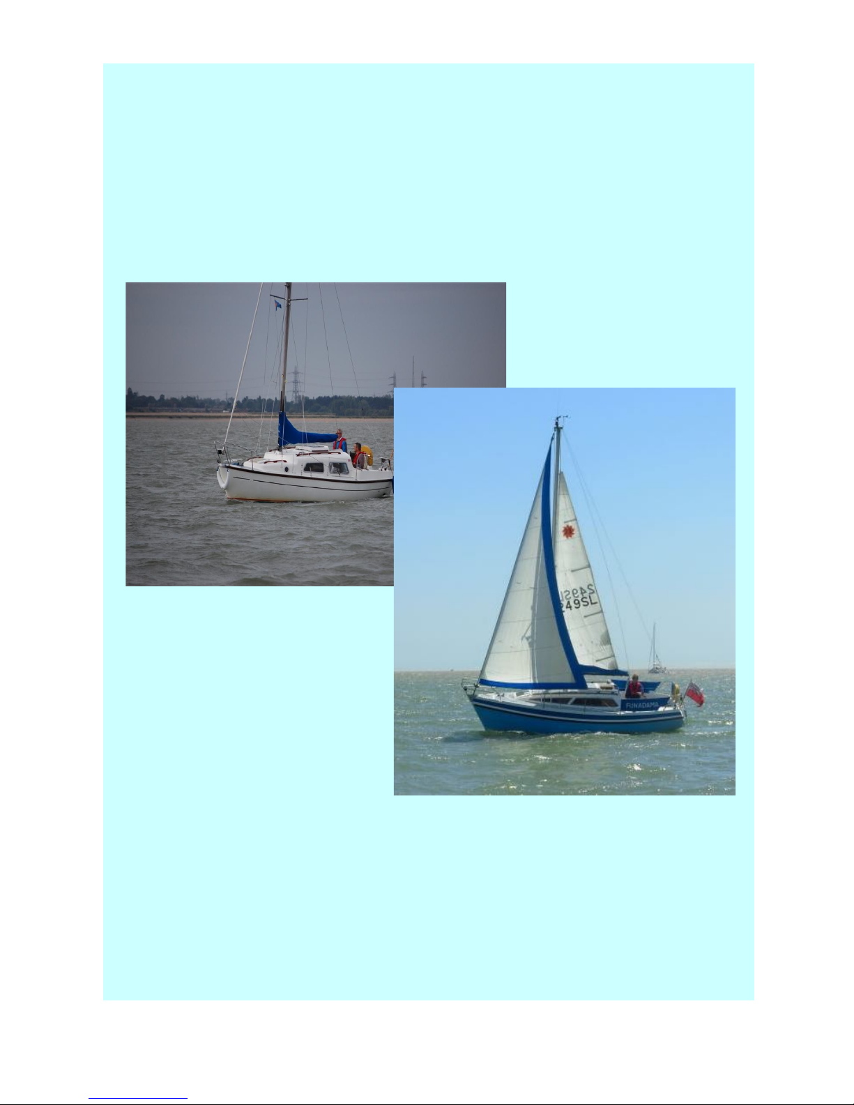
L23 and 23SL
Owners Manual
Leisure Owners Association
Issue 1
May 2012
1

Disclaimer
All the information and advice contained in this Manual is offered in good
faith, but it essentially reflects the experience and views of individual
members. The Association cannot, and does not, warrant the accuracy,
safety or practicability of any of the material.
Safety
Readers are urged to read, and to adhere to, the advice, particularly in a
Health and Safety context, given by manufacturers concerning use of
their products.
Copyright
ALL this material is the copyright of the Leisure Owners Association and/or
the Authors, and may not be reproduced without express written consent
from the Association.
Table of Contents
Section Page
Introduction 4
Starting Out
Hull and Deck
Engines and Propulsion Systems
5
8
11
Mast and Standing Rigging 14
Rudder and Skeg 16
Sails and Running Rigging 17
Windows and Hatches 20
Cabin Interior 22
Electrics and Instruments 24
2

Alphabetical Index
Alcohol vs Gas...................................................25
Alternator.....................................................26, 27
Antifouling.........................................................11
Autopilot.............................................................28
Batteries..............................................................26
Battery..........................................................27, 28
Bleeding Fuel Line.......................................13, 14
Boom............................................8, 16, 17, 19, 20
Charging.................................................26, 27, 28
Cleats............................................................11, 17
Cockpit Drains....................................................11
Deck Fittings................................................11, 12
Derusting Keels..................................................11
Electrics....................................................2, 26, 27
Engine Maintenance...............................14, 21, 27
Engine Manuals............................................14, 28
Engines.....................................................2, 13, 14
Exhaust...............................................................15
Foresail...........................................................8, 16
Fuel ........................................................13, 14, 15
Furling Gear.......................................................17
Galley.................................................................24
Gas..........................................................15, 24, 25
Grab Rail............................................................11
Halyard.......................................7, 8, 9, 19, 20, 21
Hatches...............................................2, 12, 22, 23
Heater.................................................................25
History..................................................................6
Hull...........................................................2, 10, 12
Instruments...............................................2, 26, 27
Keels.............................................................11, 12
Lazyjacks............................................................21
Lighting........................................................27, 28
Log...............................................................27, 28
Lowering Mast.............................................12, 17
Mainsail....................................................8, 17, 21
Manuals........................................................14, 28
Mast............................................2, 6, 7, 12, 16, 17
Mast and Rigging.................................................7
Mast Heel...........................................................17
NASA Log..........................................................28
Oil Leak..............................................................15
Outboard.................................................14, 27, 28
Overheating............................................13, 14, 15
Plastimo........................................................17, 21
Propeller.............................................................14
Propeller Bearing................................................15
Reefing.......................................16, 17, 19, 20, 21
Rigging Diagram............................................7, 19
Rudder......................................................2, 10, 18
Running Rigging......................................2, 16, 19
Safety................................................................2, 7
Saildrive..................................................11, 14, 15
Seal.................................11, 12, 14, 15, 18, 22, 23
Skeg..........................................................2, 10, 18
Solar Panel..........................................................28
Spirit vs Gas.......................................................25
Stanchion......................................................11, 12
Standing Rigging....................................2, 6, 7, 16
Switch Panel.................................................27, 28
Tiller.............................................................14, 18
Upholstery..........................................................25
VHF..........................................................9, 27, 28
Water Inlet....................................................14, 15
Water Pump........................................................15
Water Tank..........................................................25
Winches..............................................................12
Wind Generator..................................................28
Windows.........................................................2, 22
Wiring.....................................................26, 27, 28
.............................................................................2
3

Issue 5
April 2012
LEISURE OWNERS ASSOCIATION
L23 and 23SL Owners Manual
Section 1
Introduction
Purpose and Structure
The purpose of this Manual is to provide a comprehensive reference for these boats, including
descriptions of repairs, modifications etc that owners have carried out.
Although the two boats are considerably different in appearance, this is largely because of the
design of the topsides. The hull, rudder, skeg, mast rig etc are identical, although the internal fit
out differs slightly.
The Manual is structured in a series of Sections, each dealing with a different aspect of the boat,
eg Mast & Standing Rigging. Inevitably, there is a degree of overlap between sections, eg in
which should go methods of turning lines back to the cockpit. Each Section opens with a
description and pictures of the original arrangements – where possible – then continues with
information about repair, modification etc. The latter material has been culled from a variety of
sources, and much editing, particularly of the material extracted from the two old Forums, has
been necessary. No material from the Forum opened in March 2012 is included. It has been
produced only in an electronic form, partly because of the sheer volume of material, but mostly
because this approach allows for updated versions readily to be produced. Individual pages can
be printed as hard copies eg, to take to the boat for a particular project.
History of the Boats
Production of the original design (OD) Leisure 23 was started by Cobramold in about 1972 at their
factory in Stansted. This model was replaced by the 23SL, with its characteristic ‘sharpie’ look, in
about 1978, still being manufactured by Cobramold. But by the early 1980s, production had
passed into the hands of Brinecraft, at their Brightlingsea facility – and they changed the colour
of the below–decks mouldings from brown to white, thus providing a ready means of identifying
the builder of any one boat. Production continued until around 1986/7, when a major fire brought
things to a halt. A few boats were subsequently produced in Germany, but effectively, Leisure
yachts were no longer being made. The moulds are believed now to be in Poland.
Specifications
The original brochure for both boats can be found on our main website: L23 and SL23. Most boats
were built as twin keel versions, but some were fin keeled.
Acknowledgements
This manual has not been produced by the ‘Association’. It is a compendium of some factual
information, but it primarily reflects the advice and experience of individual members, who have
taken the time, over the years, to commit these to paper. We are extremely grateful to these folk.
Most of the material has been extracted from the Forum on the old website, and from the Forum
and the Library on the new site. If YOU have something which YOU could contribute, then please
send this to the me for inclusion in the Reference Library.
Barri Hopkins
Editor
4
Issue 3
April 2012
Section 2
Starting Out
Introduction
So, you have bought your Leisure 23 and are now looking
at the boat with its sails off, its mast down, bits of rope
and wire all over the place, desperately trying to
remember what the previous owner told you. Hopefully,
the information below will be helpful. It must be said
however, that many owners have modified their boats, and
the following guidance relates to a ‘standard’ 23 – if one
exists. Also, there are slight differences in the mast and
rigging between the 23 and 23SL.
Safety
The first and essential step is to ensure that the boat is safe to work on. If she is standing on the
ground, then chock up the skeg so that she cannot tip backwards. Similarly, another piece of
wood jammed between the forward end of the hull and the ground will stop her rocking forward.
If the boat is on a trailer, ensure that she is firmly lashed to the trailer both fore and aft. Either
couple the trailer to the car, or chock up the rear of the trailer so that it cannot tip backwards.
Mast and Rigging
Diagrams for the 23SL and 23 can be found at Rigging Diagram 23SL and Rigging Diagram L23
The mast can be raised by two people, although a third pair of hands is always useful to clear the
inevitable snagging of a wire or rope (it is much safer to let the yard or sailing club staff raise the
mast with a crane). Guidance on raising (and lowering) the mast is contained in Section 5, Mast
and Standing Rigging.
First, the mast must be properly orientated and the running rigging (rope) and standing rigging
(wire) must be correctly positioned.
Make sure that the heel of the mast is over the bow, that the sail track (groove) is facing
downwards and that the furling genoa foil is lying on top of the mast and spreaders. The backstay
should be lying underneath the mast. Drape the backstay bridle over the stern. The two cap
(upper) shrouds should each run through the alloy fitments on the end of the spreaders with split
pins or screws ensuring that the shrouds cannot escape; the spreaders themselves should be
secured to the mast by split pins or nuts and bolts. The bottle screw on each upper shroud can
now be connected to the middle deck eye. The forward and aft lower shrouds can now be
connected to their deck eyes.
Next, and a most important step loosely tie the top of each bottle screw to the guard wire with a
piece of shock cord. Failure to make the bottle screws ‘stand up’ like this can result in bent or
broken bottle screws, should they become snagged on the deck eyes as the mast is raised.
Before going on to raise the mast, check that all the running rigging is in its proper place. There
should be at least three ropes – the topping lift, main halyard and genoa halyard, plus a thin
signal halyard from the starboard spreader from which you proudly fly your Leisure Owners
pennant. There may also be a cruising ‘chute or spinnaker halyard.
The:
• topping lift runs over the rearmost sheave on the mast head (crane) and runs up and
down entirely external to the mast and should be lying underneath the spreaders
• main halyard emerges from the mast crane in front of the topping lift but runs down inside
the mast and exits via a sheave at the foot of the mast
• genoa halyard routes over the sheave on the front of the mast, and exits down inside the
mast and out via a sheave on the foot
• thin signal halyard runs through an eye or small block on the underside of the starboard
spreader.
5
At this stage, check that the radio aerial is mounted and that the masthead navigation lights,
work.
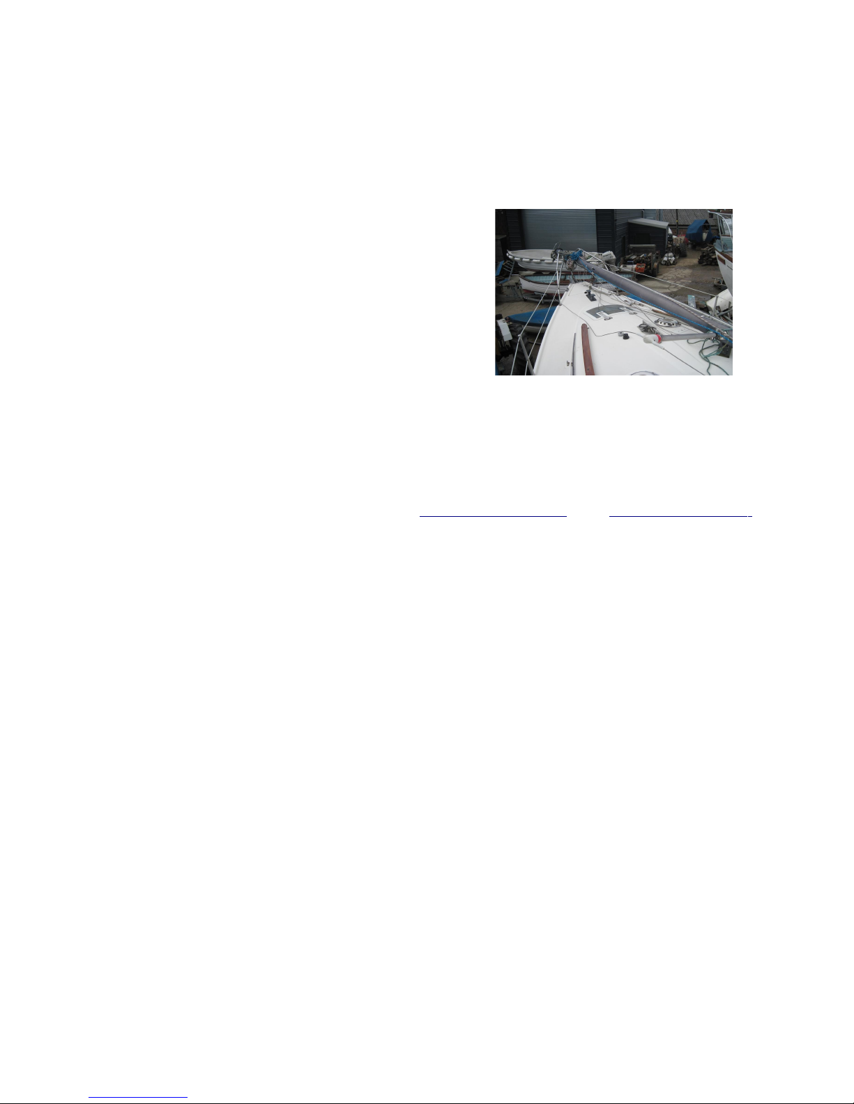
Before going on to raise the mast, it is worth spraying the sail tracks on the boom, mast, and
furling genoa foil with a dry silicone spray. This considerably eases the mounting of the sails.
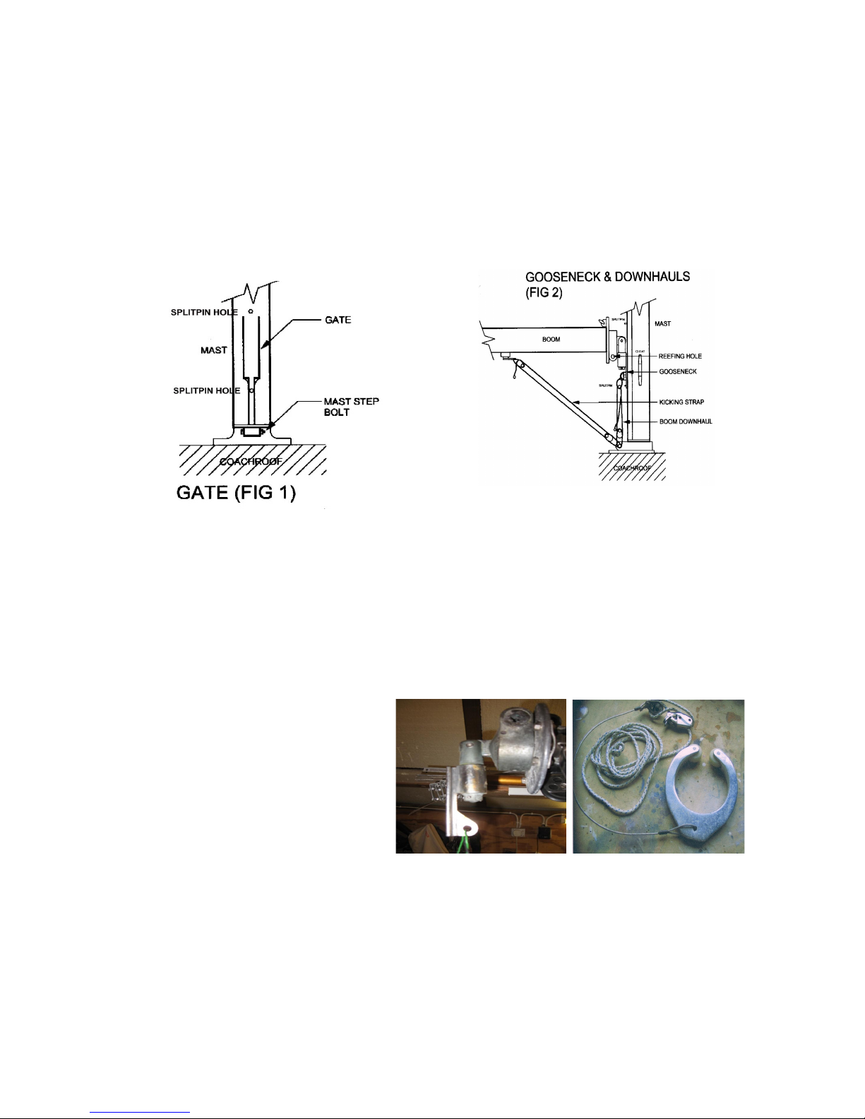
With the mast erected, insert the boom gooseneck - long bit downwards - into the slot or gate in
the mast (Fig 1), with the sail track of the boom uppermost. Insert the split pin (which should be
dangling on a piece of cord from the mast) into the hole in the mast sail track below the gate and
let the boom rest on it. Connect the topping lift to the end of the boom to support it in a
horizontal position, and shackle the main sheet to the tang on the end of the boom and to the
horse – the slider on the rail across the companion way on the 23SL or, on some 23s, across the
transom. You are now ready for the mainsail.
.
Mainsail
Insert the aft corner (clew) of the sail into the groove on the boom and ease the sail along the
boom. Shackle or lash the forward end (tack) to the lug on the roller reefing plate, and lash the
other end to the cast eye on the end of the boom. Shackle the main halyard to the head of the
sail. Insert the head of the sail into the gate and haul the sail up, feeding the sliders or boltrope
into the gate as you go. Make off the halyard on a cleat on the mast.
Insert the second split pin into the hole in the track just above the upper gate. There should be a
boom downhaul which is fitted between the lug on the under side of the gooseneck and the mast
step bolt so that the mainsail, once raised and with the lower split pin removed, can be tensioned
by pulling the boom down with the downhaul (Fig 2).
Originally, the main sail was furled by
inserting a cranked handle into the
gooseneck fitting and turning to wind the
sail around the boom. The kicking strap
function was provided via a large
horseshoe claw, which allowed the boom
and sail to rotate within it. If you have a
claw, it should be lashed to the aft end of
the boom so that it lies about 3ft from the
mast. A downhaul should be fitted between
the claw and the mast step bolt. However, many owners have changed to slab reefing, where the
sail is pulled down onto the boom and not wound round it. In this case, there should be a fitting
underneath the boom so that a kicking strap, with its own jamming block, can be connected
between it and the mast step (Fig 2).
Foresail
As originally supplied, both models had a forestay onto which the genoa was simply clipped by
piston hanks. Many owners have since converted to furling genoas, where the sail is wound onto
a foil which rotates around the forestay. There are many different models in existence, but the
6

principles are the same.
Before hoisting the genoa – on a calm day - check that the forestay is tight; if it is slack,
problems will occur. Shackle the halyard to the top mounting of the top swivel of the furling kit,
feed the head of the genoa into the sail track and shackle it to the lower mounting of the top
swivel. Haul on the genoa halyard whilst a second pair of hand feeds the sail. When fully hoisted,
shackle the foot of the sail to the mounting on the lower drum. Apply as much tension as possible
to the halyard, and make it off on a cleat on the mast.
The next task is to get the reefing line – assuming it is a single line – wound onto the drum. Roll
the genoa around the foil by twisting the foil, so that the sail is wound as tightly as possible, with
the UV strip on the outside of the bundle. Put a tie around it. Connect the reefing line to the
drum and twist the bundle to put lots of turns on the drum. Some careful thinking is required to
determine the correct direction of twist!! Connect the genoa sheets to the clew of the genoa and
then test the unfurling/furling action, keeping slight tension on the genoa sheets. If the genoa
won’t furl completely, you will need to remove the sheets and put a few more turns on the drum.
Engine
Your engine could be an outboard, or an inboard diesel or petrol, sail drive or shaft drive – the
latter is not common. It is difficult to offer any advice with such a wide range of possible motors.
The following pointers are largely obvious. Before going afloat, or leaving the mooring or
pontoon, ensure that:
• for inboard engines, the cooling water inlet valve is open, and that water is emerging from
the exhaust when the engine is run
• for outboard engines, the vent screw on the top of the tank is open, and that water is
emerging from the tell-tale tube when the engine is run
• you have plenty of fuel
• the propeller turns when a gear is selected
Miscellaneous
Before going afloat, or leaving the mooring or pontoon, ensure that:
• you have a list of all the things you should do/check – and do, or check them
• all seacocks (except the engine cooling water intake) are shut, and that the log impeller,
or the log blanking cap or plug, is in place.
• any gas supply is turned off at the cylinder
• you have a serviceable boathook – preferably two
• you and your crew are wearing buoyancy aids
• the VHF radio works
• you are flying your ensign – and of course, your LOA pennant
from the starboard spreader.
7

Issue 3
Mar 2012
Section 3
Hull & Deck
General
Both versions have identical hulls, but the superstructure differs markedly. The SL is readily
identified by its ‘sharpie’ form, with its sloping coach roof, whereas the original design had a
stepped coach roof. This, and other differences in design can be seen in the brochures for the two
models Brochures. Both fin and twin keel versions were built, though the latter predominates.
Nine colours were available, at extra cost, but the most popular colour was white.
Most boats have a tendency to list to port, a feature which some owners have compensated for
by, eg, carrying an inflatable in the cockpit starboard locker, or shifting a battery to the starboard
side.
Hull
The hull itself is a very substantial one-piece GRP construction, with the thickness of the material
approaching 25mm in the bows. The join between the hull and superstructure is covered
externally by a teak rubbing strake, through bolted and, in most cases, with the screw heads
recessed and plugged; some have bolts whose heads are simply countersunk. Internally, the bond
is covered by a broad teak ply strip. There are very few known cases of osmosis with these hulls.
The skeg and the keels are both bolted-on additions (Rudders and Skegs are covered in Section
6). The keels are rough steel castings, and are inevitably subject to rusting and pitting where the
protective coating has been damaged. The effects are more cosmetic than serious, and
treatment of rusty keels is the subject of a few items below. They are affixed to the hull by
stainless studs, whose stainless nut are accessible below the cabin sole, but are covered with a
thick coating of flo-coat.. No problems are known to have arisen from this method of securing
the keels .
The issue of antifouling would fill a manual in its own right, particularly the question of which
product to use. Its largely a question of 'you pays your money and takes your choice'. There are,
however, a few basic guidelines:
• make good any significant damage with an epoxy filler
• lightly abrade the existing coating, with WET abrasive paper. Doing it with dry paper
produces toxic dust.
• do not use hand or power wire brushes to remove rust. This action polishes the metal.
• check that your intended antifouling is compatible with the existing coating. If you are
unsure, put a tie coat on first.
• apply the antifoul generously.
Deck and Coach Roof
The two GRP skins of the roof enclose a balsa core; these skins merge at the edges of the roof to
form solid GRP walls, of irregular thickness, in which the windows are fitted. The side decks also
incorporate a balsa core. All the cockpit benches, walls, bulkheads etc are single skin GRP. There
are moulded-in non-slip areas in the gelcoat, and winch pads on the coach roof and coaming. Few
problems are known to have arisen, with this form of construction, except where water leaks
around fittings have caused the balsa core to soften, and then be crushed as attempts are made
to tighten the loose fittings. There have also been one or two cases where delamination has
occurred on the side decks; ingress of water through cracks causing the upper deck skin to
bubble up. The cockpit floor is 20mm solid grp.
8
 Loading...