

Leister WELDPLAST S1 Operating Instructions Manual
®
Leister Technologies AG
Galileo-Strasse 10
CH-6056 Kaegiswil/Switzerland
Tel. +41 41 662 74 74
Fax +41 41 662 74 16
www.leister.com
sales@leister.com
2
21
40
59
78
97
D
GB
F
I
E
NL
WELDPLAST
S1
2
Bedienungsanleitung (Original-Bedienungsanleitung)
Bedienungsanleitung vor Inbetriebnahme aufmerksam
lesen und zur weiteren Verfügung aufbewahren.
Leister WELDPLAST S1
Hand-Schweissextruder
Anwendung
• Extrusionsschweissen von folgenden Materialien:
PP / PE-HD / PVC-U / PVC-C / PVDF
• Weitere Materialen auf Anfrage
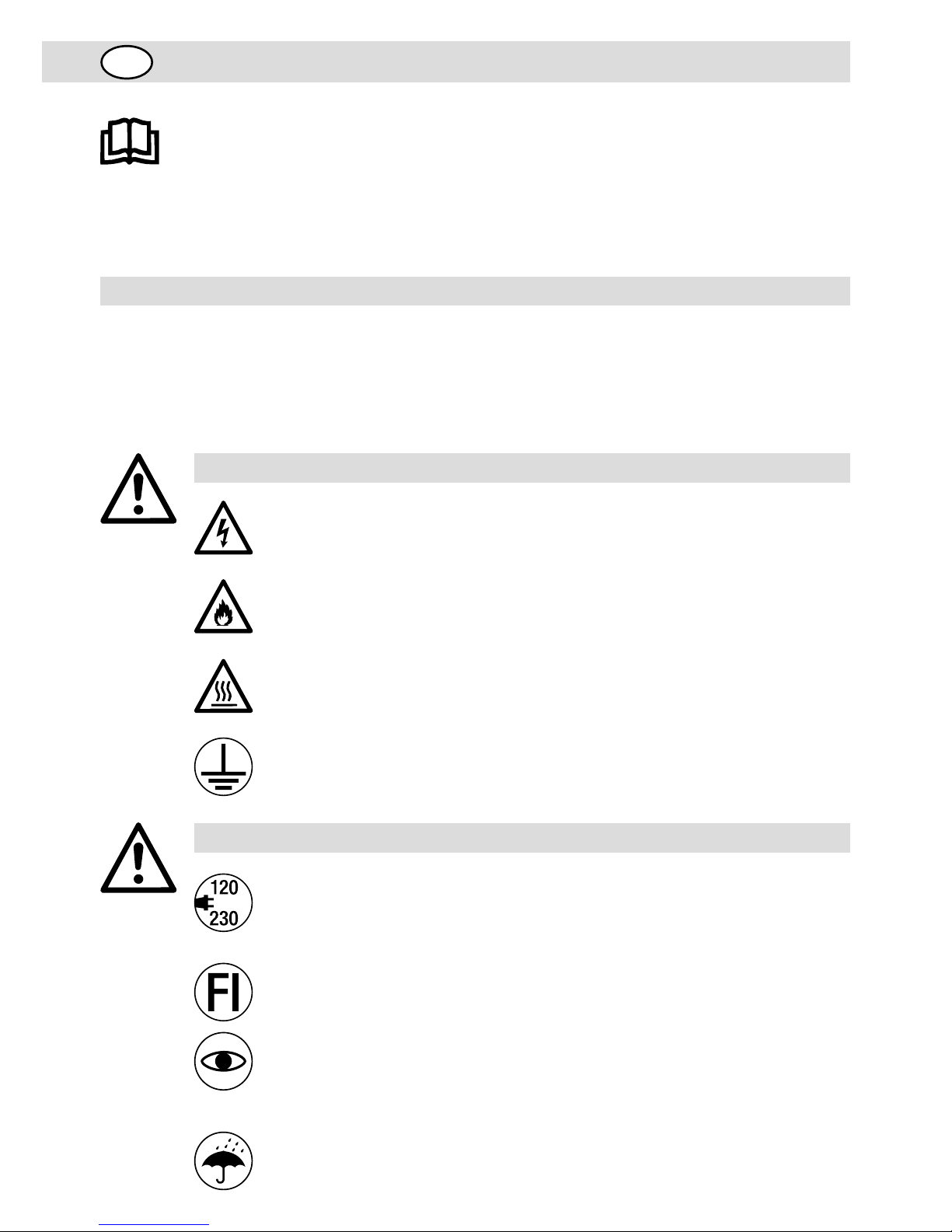
Warnung
Lebensgefahr beim Öffnen des Gerätes, da spannungsführende Komponenten und
Anschlüsse freigelegt werden. Vor dem Önen des Gerätes Netzstecker aus der Steckdose
ziehen.
Feuer- und Explosionsgefahr bei unsachgemässem Ge brauch des Hand-Schweissextruders (z.B. Überhitzung von Material) besonders in der Nähe von brennbaren
Materialien und explosiven Gasen.
Verbrennungsgefahr! Blanke Metallteile und austretende Masse nicht in heissem
Zustand berühren. Gerät abkühlen lassen. Heissluftstrahl und austretende Masse
nicht auf Personen oder Tiere richten.
Gerät an eine Steckdose mit Schutzleiter anschliessen. Jede Unterbrechung des Schutzleiters innerhalb oder ausserhalb des Gerätes ist gefährlich!
Nur Verlänge rungs kabel mit Schutzleiter verwenden!
Vorsicht
Nennspannung, die auf dem Gerät angegeben ist, muss mit der Netzspannung
übereinstimmen.
Bei Ausfall der Netzspannung müssen Hauptschalter und Antrieb ausgeschaltet werden
(Arretierung lösen).
FI-Schalter beim Einsatz des Gerätes auf Baustellen ist für den Personenschutz dringend
erforderlich.
Blendungsgefahr ! Direkter Blickkontakt mit dem LED-Lichstrahl ist zu vermeiden.
Gerät muss beobachtet betrieben werden. Wärme kann zu brennbaren Materialien
gelangen, die sich ausser Sichtweite befinden.
Gerät darf nur von ausgebildeten Fachleuten oder unter deren Aufsicht benützt
werden. Kindern ist die Benützung gänzlich untersagt.
Gerät vor Feuchtigkeit und Nässe schützen.
D
3
Konformität
Leister Technologies AG, Galileo-Strasse 10, CH-6056 Kaegiswil/Schweiz bestätigt, dass dieses Produkt
in der von uns in Verkehr gebrachten Ausführung die Anforderungen der folgenden EG-Richtlinien erfüllt.
Richtlinien: 2006/42, 2004/108, 2006/95, 2011/65
Harmonisierte Normen: EN 12100, EN 55014-1, EN 55014-2, EN 61000-6-2, EN 61000-3-2,
EN 61000-3-3, EN 62233, EN 60335-2-45, EN 50581
Kaegiswil, 20.10.2014
Bruno von Wyl, CTO Andreas Kathriner, GM
Entsorgung
Elektrowerkzeuge, Zubehör und Verpackungen sollen einer umweltgerechten Wiederverwertung
zugeführt werden. Nur für EU-Länder: Werfen Sie Elektrowerkzeuge nicht in den Hausmüll!
Gemäß der Europäischen Richtlinie 2002/96 über Elektro- und Elektronik-Altgeräte und ihrer
Um setzung in nationales Recht müssen nicht mehr gebrauchsfähige Elektrowerkzeuge getrennt
gesammelt und einer umweltgerechten Wiederverwertung zugeführt werden.
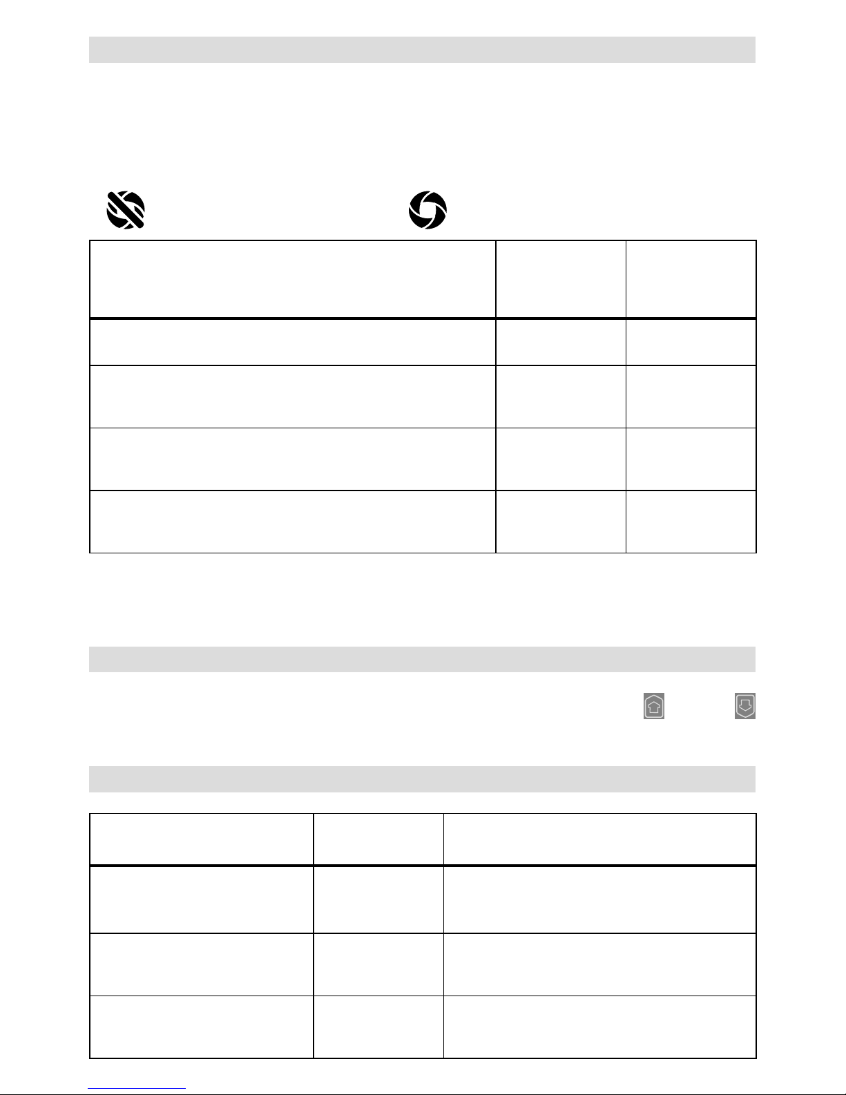
Technische Daten
Spannung V~ 100 120 230
Leistung W 1500 1800 1600
Frequenz Hz 50/60 50/60 50/60
Luft-Temperatur °C max. 360
Plastifizier-Temperatur °C max. 260
Ausstoss (Ø 3 mm) kg/h HD-PE 0.2 – 0.5; PP 0.2 – 0.5
Ausstoss (Ø 4 mm) kg/h HD-PE 0.3 – 0.8; PP 0.3 – 0.75
Schweissdraht mm Ø 3 / Ø 4
Emissionspegel L
pA
(dB) 76 (K = 3 dB)
Masse L × B × H mm 435 × 264 × 91 (ohne Schweissschuh)
Gewicht kg 4.7 (ohne Netzanschlussleitung)
Konformitätszeichen
Sicherheitszeichen
Schutzklasse I
Technische Änderungen vorbehalten

4
Gerätebeschreibung
1 Hauptschalter
2 Ein-/Ausschalter Antrieb
3 Potentiometer
4 Arretierung Antrieb
5 Display
6 Handgri
7 Mantelheizung
8 Schweissschuh
9 Vorwärmdüse
10 Schutzrohr
11 Schweissdraht-Einführung
12 Gerätegri
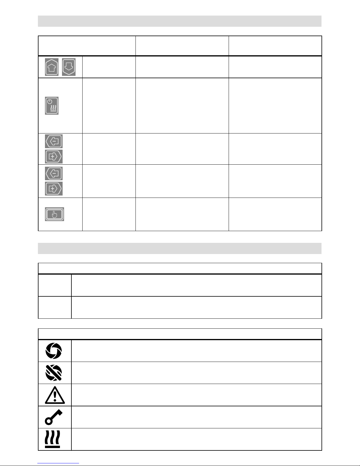
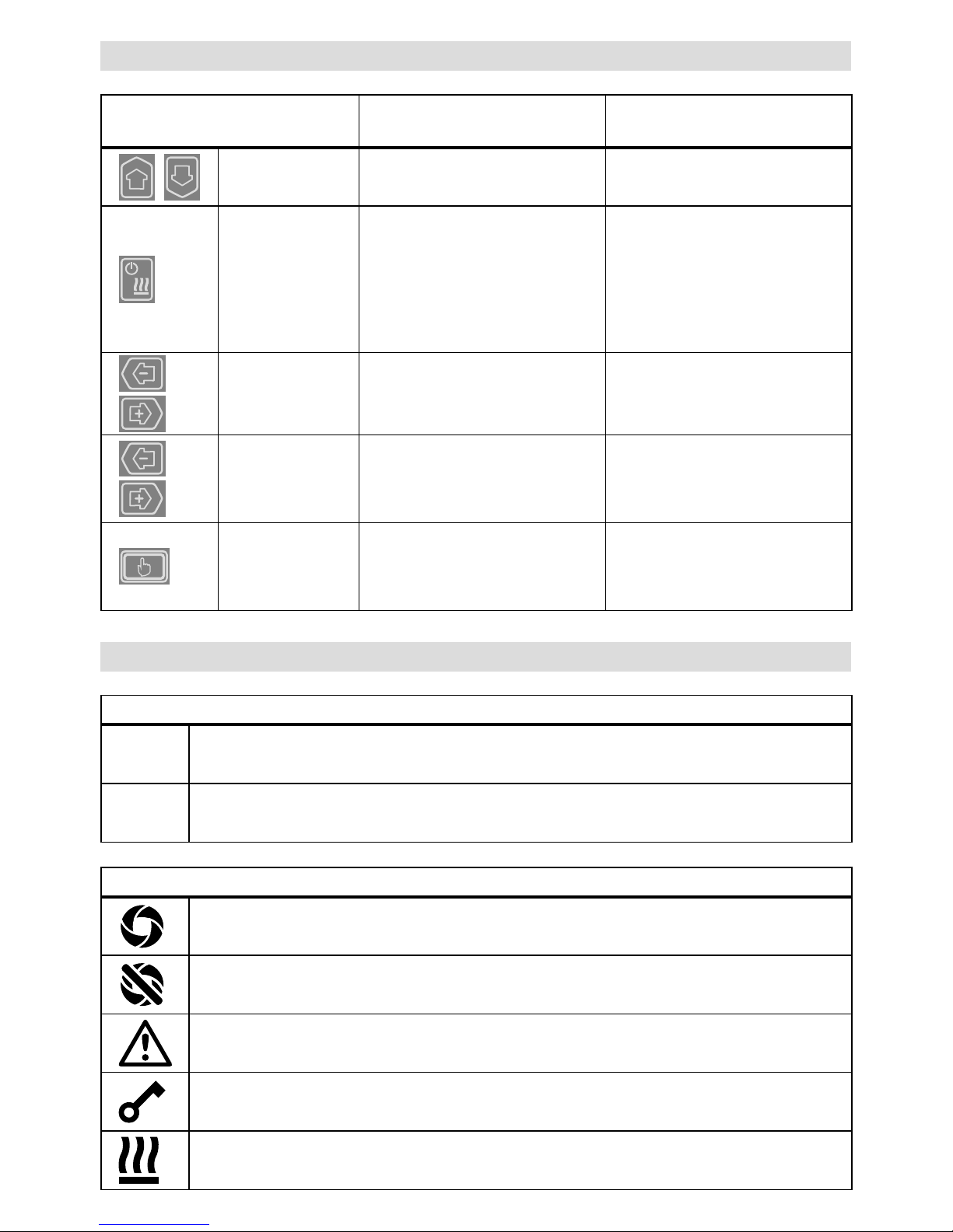
Bedieneinheit
21 Taste «Auf»
22 Taste «Ab»
23 Taste Heizung «Ein / Aus»
24 Taste «Minus»
25 Taste «Bestätigen»
26 Taste «Plus»
Display
27 Funktionsanzeige
28 Arbeitsanzeige
29 Statusanzeige «Bereich 1»
30 Statusanzeige «Bereich 2»
13 Netzanschlussleitung
14 Heizelement - Schutzrohr
15 Gebläse (bürstenlos)
16 Heissluftführung
17 Extrudierdüse
18 Klemmschraube Schweissschuh
19 Klemmschraube Vorwärmdüse
20 Klemmschelle
31 LED-Beleuchtung
32 Ablagebolzen
33 Klemmschraube Heissluftführung
2
3
4
18
8
17
%
100
°C
230
°C
260
25
28
30
27
26
21
22
23
24
29
1
5
6
7
8
19
10
11
12
13
14
15
16
20
9
31
11
32
33
5
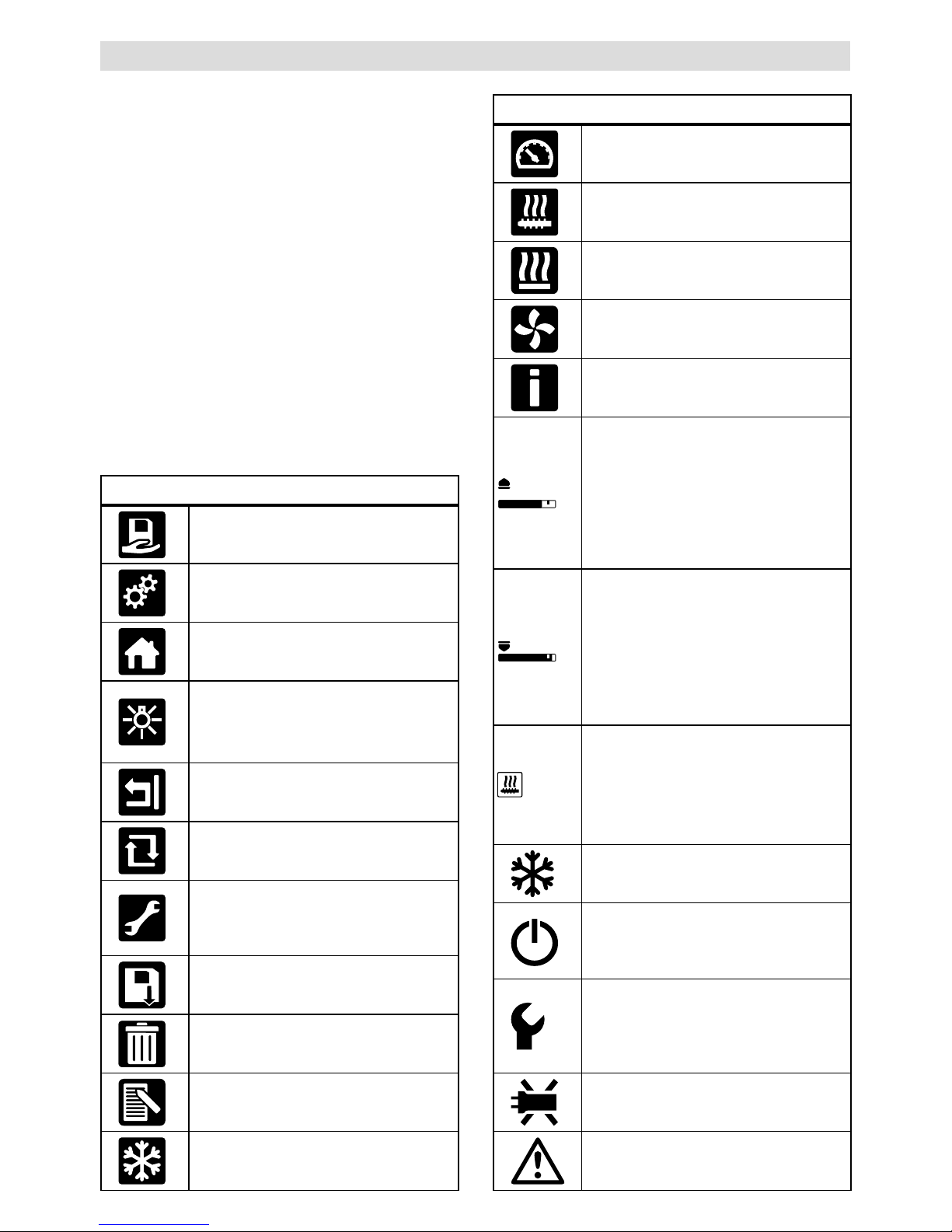
Bedieneinheitsbeschreibung
Displaybeschreibung
Statusanzeige «Bereich 1» (29)
PE-HD
Aktuell ausgewähltes Profil. Bei Profilnamen mit mehr als 6 Zeichen werden zuerst die ersten
6 Zeichen angezeigt, anschliessend die verbleibenden Zeichen.
1m16s Verbleibende Zeit bis Antrieb freigegeben wird (1 min. / 16 sek.)
Statusanzeige «Bereich 2» (30)
Antrieb freigegeben
Antrieb nicht freigegeben
Warnung vorhanden (Kohlenbürsten / Antrieb)
Tastensperre (erscheint nur bei aktiver Tastensperre)
Luft- und Plastifizier-Heizung ist eingeschaltet
Tastaturmodus
Aktuelle Auswahl in der
Arbeitsanzeige
Aktuelle Auswahl in der
Funktionsanzeige
Auf (21)
Ab (22)
Verändern der Position innerhalb
der Arbeitsanzeige
Wechsel von der Funktionsanzeige in die Arbeitsanzeige
Heizung
Ein / Aus (23)
Keine Funktion
Wechsel vom Schweissmodus
in Abkühlvorgang
Wechsel von Abkühlvorgang in
den Schweissmodus
Wechsel von Startanzeige in
den Schweissmodus
Minus (24)
Plus (26)
(kurz drücken)
Einstellen des gewünschten
Sollwertes in 5°C - bzw.
5% - Schritten.
Verändern der Position in der
Funktionsanzeige
Minus (24)
Plus (26)
(drücken und
halten)
Einstellen des gewünschten Sollwertes in 10°C - bzw.
10% -Sch rit te n.
Verändern der Position in der
Funktionsanzeige
Bestätigen (25)
Eingestellter Wert wird direkt
übernommen und die Auswahl
springt direkt in die
Funktionsanzeige zurück
Ausgewählte Funktion wird
ausgeführt
6
Funktions- und Arbeitsanzeige
• In der Funktions- und Arbeitsanzeige definiert
immer das markierte dargestellte Feld oder Symbol
die aktuelle Auswahl.
• In der Arbeitsanzeige werden immer die Istwerte
angezeigt, ausser wenn eine Position ausgewählt
ist, erscheint der Sollwert.
• Ist «Show Set Values» aktiviert erscheint der Istund Sollwert (klein).
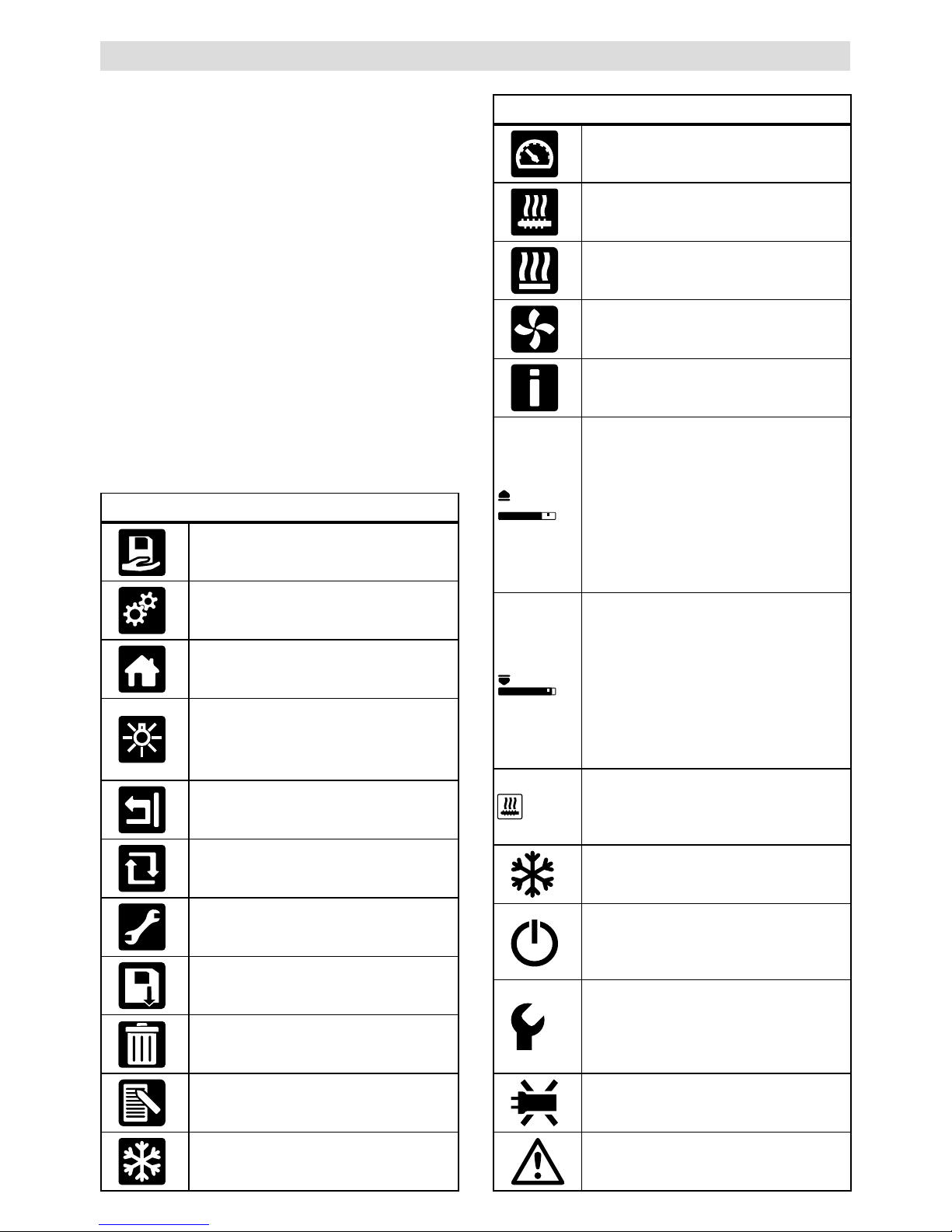
Funktionsanzeige (27)
Freie und vordefinierte Profile
auswählen
Einstellungen
Zurück zur Arbeitsanzeige
(direktes Verlassen eines Menüs)
LED ein-/ ausschalten.
Diese Funktion ist nur vorhanden,
wenn die LED aktiviert wurde.
Eine Ebene zurück
Einstellungen oder Stundenzähler
zurücksetzen
Service Menü
(nur über Passworteingabe verfügbar)
Speichern
Ausgewählte Position löschen
Ausgewählte Position bearbeiten
Abkühlvorgang einleiten
Arbeitsanzeige (28)
Sollwert:
Ausstossmenge Antrieb [%]
Sollwert:
Plastifizier-Temperatur [°C / °F]
Sollwert:
Luft-Temperatur [°C / °F]
Sollwert:
Luftmenge [%]
Informationsfenster
°C
200
230
Der Pfeil nach oben und der Fortschrittsbalken zeigen an, dass der
Sollwert (Markierung im Fortschrittsbalken) noch nicht erreicht ist (zu kalt).
Der blinkende Wert ist der Istwert. Der
Wert neben dem Fortschrittsbalken ist
der eingestellte Sollwert.
°C
250
230
Der Pfeil nach unten und der Fortschrittsbalken zeigen an, dass der Sollwert (Markierung im Fortschrittsbalken)
noch nicht erreicht ist (zu heiss). Der
blinkende Wert ist der Istwert. Der
Wert neben dem Fortschrittsbalken ist
der eingestellte Sollwert.
°C
250
230
Ist «Show Set Values» aktiviert,
wird die Isttemperatur (gross) und die
Solltemperatur (klein) dargestellt.
Abkühlvorgang
Gerät im Standby-Modus. Das Gerät
wird nach Ablauf des Zählers den
«Cool down modus» starten
Gerät hat einen Fehler. Zusätzlich
erscheint ein Fehlercode (Gerät nicht
mehr einsatzbereit). Autorisierte
Service-Stelle kontaktieren
Heizelement-Luft defekt
Gerätetemperatur zu hoch.
Gerät abkühlen lassen.
7
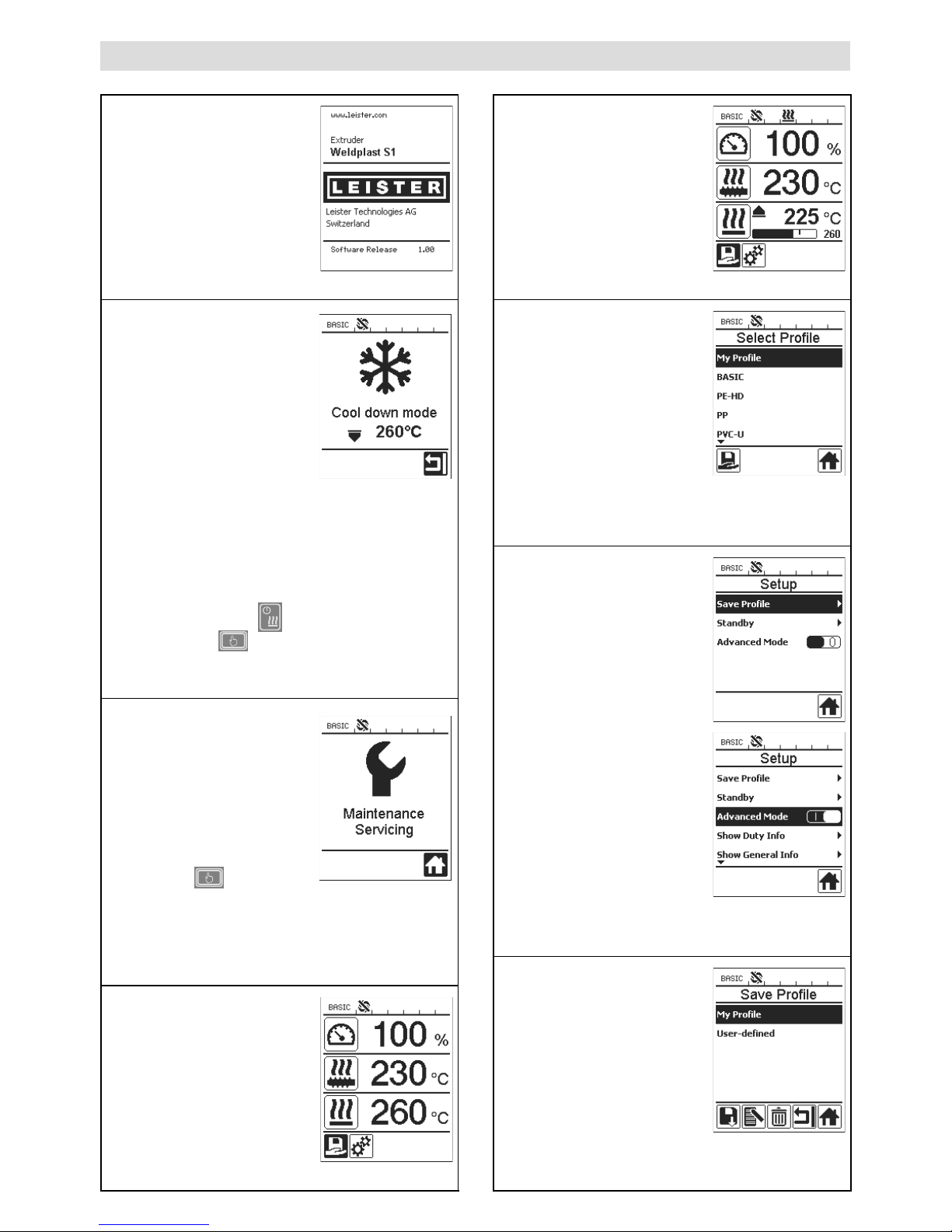
Aufstartanzeige
Schweissen
Anzeige während dem
Aufheizvorgang
Select Profile
(Profilauswahl)
Wählen Sie ein von Ihnen
definiertes oder ein durch
Leister vorgegebenes Profil
aus. Die Profilauswahl ist
unter dem Kapitel «Select
Profile» Seite 13 detailliert
beschrieben.
Setup (Einstellung)
In der Grundeinstellung
gelangen Sie über das
Menü «Setup» in die Profil-
speicherung und in
die Standbyfunktion.
Durch auswählen des
«Advanced Mode» stehen
diverse weitere Einstellungsmöglichkeiten zur Verfügung.
Save profile
(Freie Profile definieren)
Die freie Profilspeicherung
ist unter dem Kapitel
«Profile definieren»
Seite 15 / 16 detailliert
beschrieben.
Aufstartanzeige
Anzeige beim Aufstart mit
Software Release der
Leistungseinheit.
Cool down mode
(Abkühlen)
In diesem Modus sind
die Heizungen ausgeschaltet und das Gerät ist
im Abkühlmodus. Ist beim
Einschalten des Gerätes
die Vorwärmlufttemperatur
grösser als 100 °C, wechselt das Gerät automatisch in den «Cool down mode». Der Vorgang ist
abgeschlossen, wenn die Vorwärmlufttemperatur 2 min. unter 100 °C liegt.
Sollen die Heizungen wieder eingeschaltet werden,
muss die Taste (23)
«Heizung Ein/Aus» oder
die Taste (25) «Bestätigen» gedrückt.
werden.
Maintenance servicing
(Wartungsservice)
Ist das Wartungsintervall für
den Antriebsmotor erreicht,
erscheint nach der Aufstartanzeige «Maintenance
Servicing».
Mittels
Taste (25)
«Bestäti-
gen»
kann weiter
gearbeitet
werden. Das Gerät muss zwingend zu
Ihrer Service stelle gebracht werden.
Startanzeige
In der Startanzeige werden
alle Sollwerte dargestellt.
Die Heizung ist noch nicht
eingeschaltet, es können
jedoch alle Sollwerte bereits
eingestellt werden.
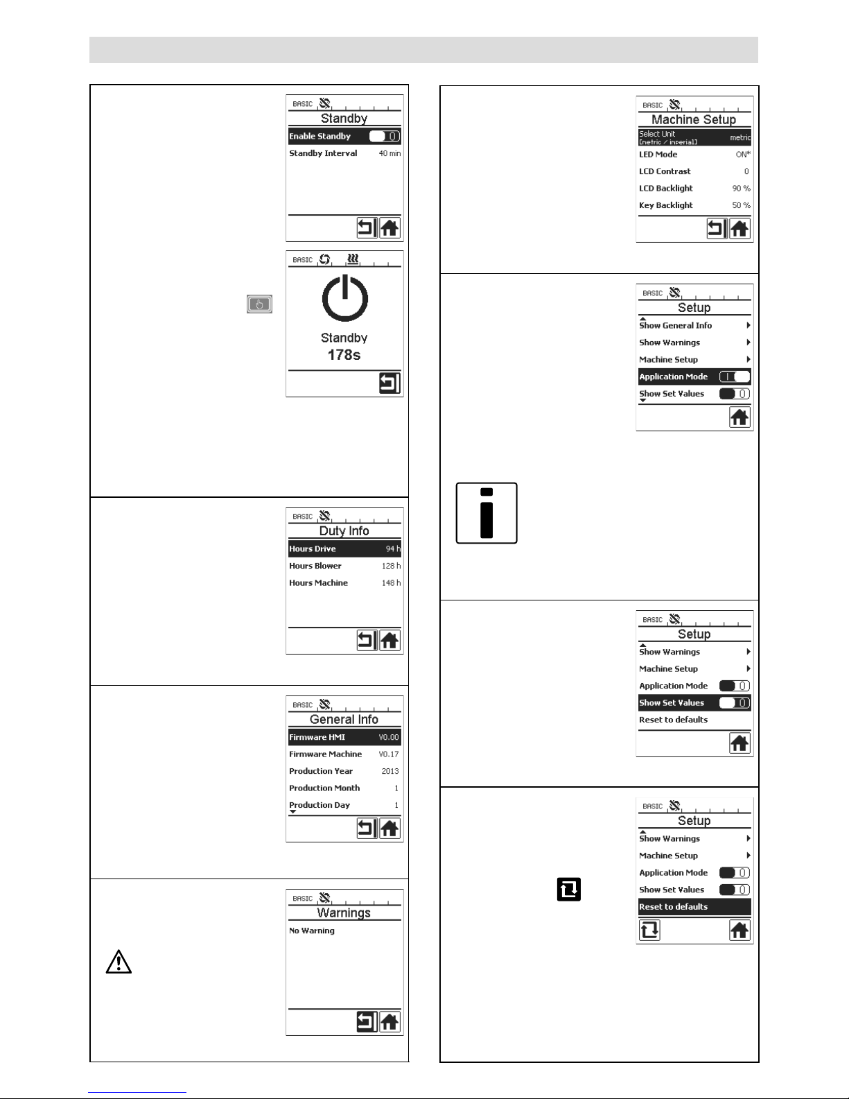
Übersicht der Arbeitsanzeige
8
Übersicht der Arbeitsanzeige
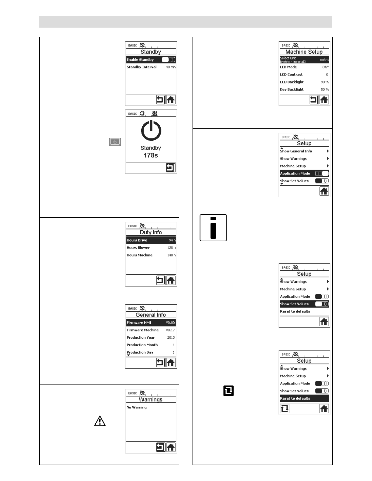
Standby (Bereitschaft)
Ist der Standbymodus
aktiviert und wird während
der unter «Standby Interval»
definierten Zeit keine Taste
auf der Bedieneinheit oder
der Ein- / Ausschalter
Antrieb (2) betätigt, wechselt
das Gerät automatisch in
die Standbyanzeige. Wird
während den folgenden
180 sek. die Taste (25)
«Bestätigen» nicht gedürckt,
startet automatisch der
Abkühlmodus.
Duty Info
Hours Drive: aktuelle Laufzeit
des Antriebs (rückstellbar).
Hours Blower: aktuelle
Laufzeit des Gebläses.
Hours Machine: aktuelle
Laufzeit der Maschine.
General Info
Firmware HMI: Softwareversion der Displayeinheit
(Kommunikationsmodul).
Firmware Machine: Softwarerevision Leistungseinheit.
Production Info: Angaben zum
Produktionszeitpunkt.
Warnings
Liegt eine Warnung vor, wird
dies in der Statusanzeige
durch das Symbol
signalisiert. Im Menü
«Warnings» finden Sie
genauere Angaben zur
aktuellen Warnung.
Machine Setup
Die Einstellungen der
Maschine sind unter
dem Kapitel «Maschinen
Einstellungen» detailliert
beschrieben.
Application Mode
Ist der «Application Mode»
aktiviert, haben Sie in der
Arbeitsanzeige detaillierte
Angaben zur Ist-Plastifizier-
Temperatur und Auslastung
von Heissluftgebläse und
Plastifizier-Heizung.
Plast : 80 % 222 °C
Heat : 40 % 197 °C
Amb. : 25 °C
Mains : 50 Hz
Ist «Show Set Values»
aktiviert, wird die
Ist-Temperatur (gross) und
die Soll-Temperatur (klein)
dargestellt.
Reset to defaults
Wird das Menü «Reset to
defaults» ausgewählt und
durch Auswählen der
Funktion
bestätigt,
werden sämtliche Kundenspezifischen Profile gelöscht.
Einstellungen welche über
das Setup Menü verändert
wurden, werden auf
Werkseinstellung zurückgesetzt.
9
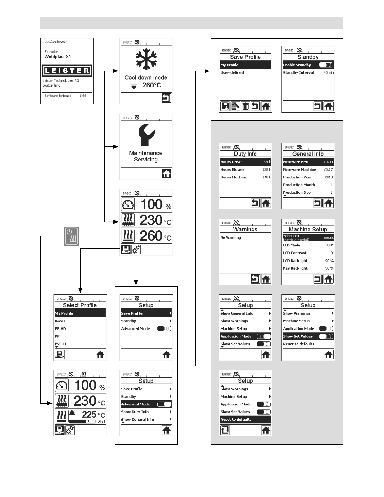
Menüführung
Nur im «Advanced Mode» verfügbar
10
Arbeitsumgebung / Sicherheit
Vor Inbetriebnahme Netzanschlussleitung (13) und Stecker sowie Verlängerungskabel auf
elektrische und mechanische Beschädigung überprüfen.
Der Hand-Schweissextruder darf nicht in explosionsgefährdeter bzw. entzündbarer Umgebung eingesetzt werden. Auf sicheren Stand bei der Arbeit achten. Netzanschlussleitung und
Schweissdraht müssen frei beweglich sein und dürfen den Anwender oder Dritte bei der Arbeit
nicht behindern.
Hand-Schweissextruder auf feuerfeste Unterlage stellen! Heisse Metallteile und Warmluftstrahl
müssen genügend Abstand zu Unterlage und Wänden haben.
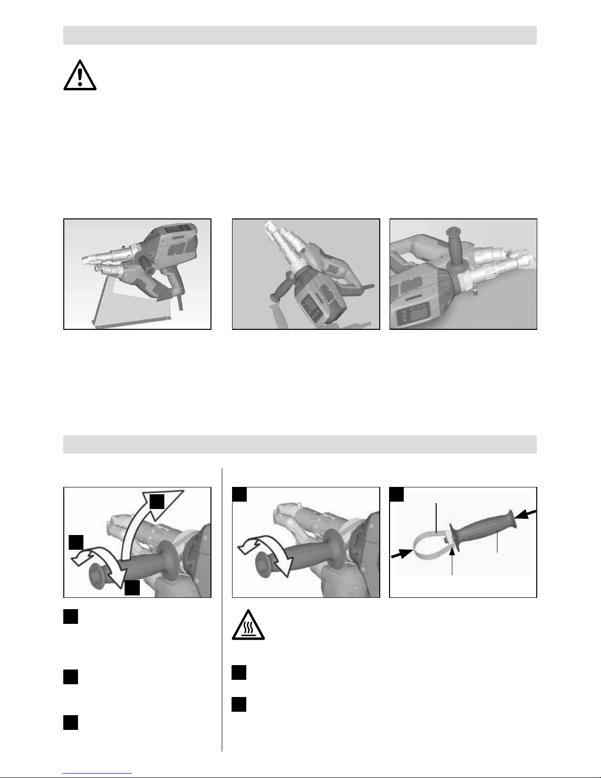
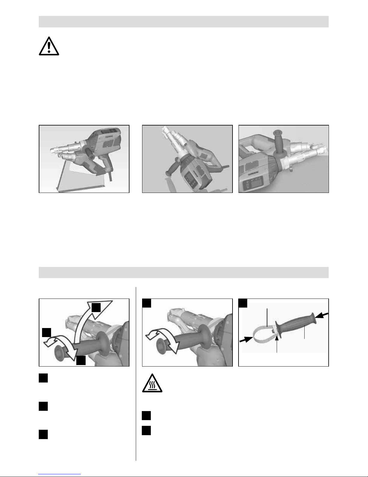
Einstellung Handgri
Arbeitsplatz
1
2
3
1
Durch Drehen des Hand -
gris (6) gegen den
Uhrzeiger sinn Klemmung
lösen.
2
Handgri (6) in die ge-
wünschte Arbeitsposition
bringen.
3
Durch Drehen des Hand-
gris (6) im Uhrzeigersinn
Klemmung wieder festziehen.
Zur Inbetriebnahme und Ablage
des Hand-Schweissextruders bietet
Leister eine Geräte ablage an.
Bei Unterbruch der Schweiss arbeiten ist der Antrieb mit dem Ein-/Aus-
schalter Antrieb (2) abzuschalten.
Den Hand-Schweissextruder mit entsprechend eingestelltem und fest
ange zoge nem Handgri (6) gemäss Abbildung auf eine stabile, feuerfeste
Unterlage oder Ablagebolzen (32) stellen.
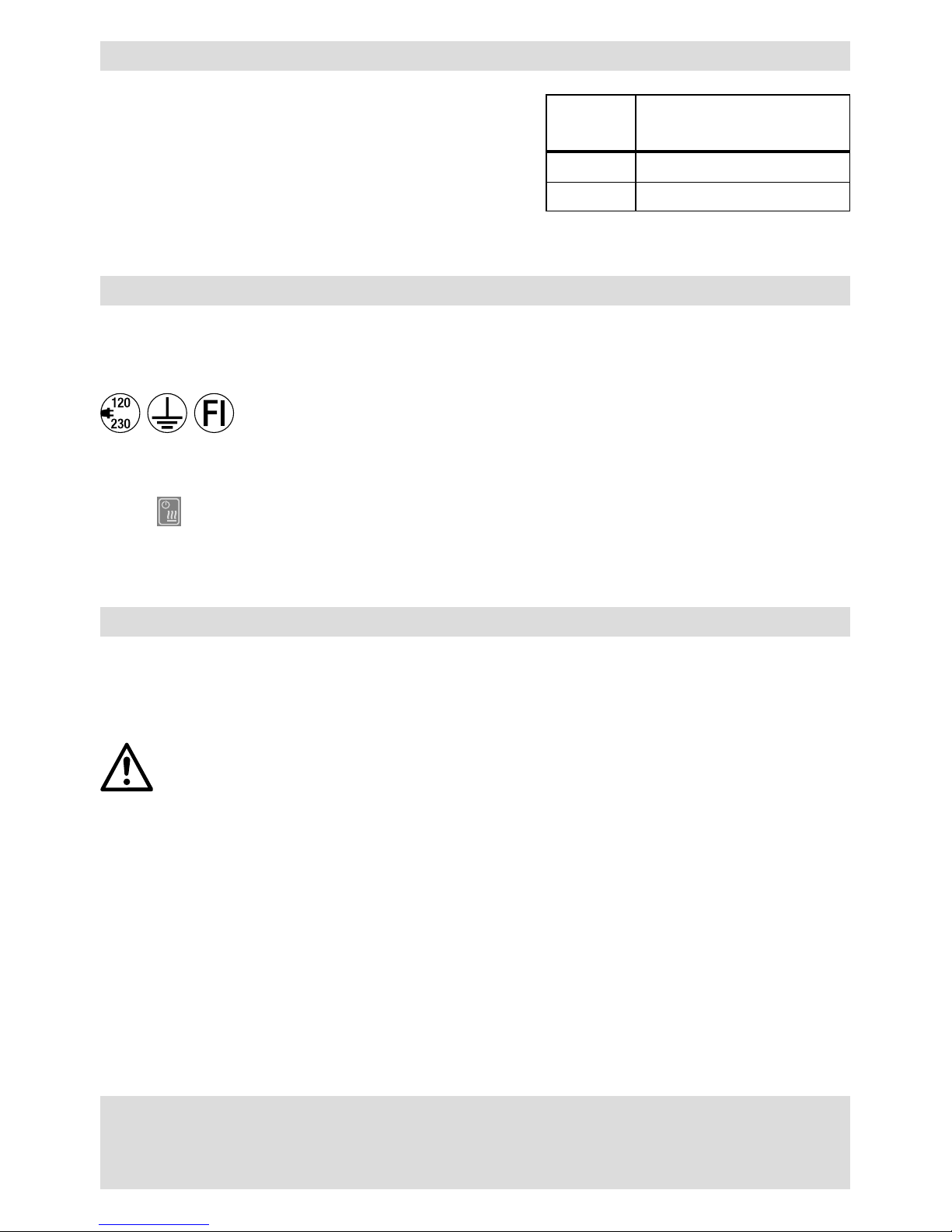
Handgri
Demontage / Montage Handgri
Demontage Handgri
1
Durch Drehen des Handgris (6) gegen den Uhrzeigersinn
Klemmung lösen.
2
Mittels Drücken auf den Handgri (6) und auf die Klemmschelle
(20) önet sich der Verschluss (siehe Pfeile). Handgri (6) mit
Klemmschelle (20) entnehmen.
Montage Handgri erfolgt in umgekehrter Reihenfolge.
1 2
Verschluss
Handgri (6)
Klemmschelle (20)
Verbrennungsgefahr! Gerät abkühlen lassen
11
Verlängerungskabel
• Bei Verwendung von Verlängerungskabeln auf den Mindestquerschnitt achten:
• Verlängerungsleitung muss für den Einsatzort (z.B. im Freien)
zugelassen und entsprechend gekennzeichnet sein.
• Bei Verwendung eines Aggregates zur Energieversorgung gilt
für dessen Nennleistung: 2 × Nennleistung Hand-Schweiss–
extruder.
Länge
[m]
Mindest-Querschnitt
(bei 100 – 230V~) [mm
2
]
Bis 19
2.5
20 – 50 4.0
• Schalten Sie den Extruder über den Hauptschalter (1) ein. Je nach Vorwärmlufttemperatur erscheint auf
dem Display (5) die Aufstartanzeige oder «Cool down mode». Durch Drücken der Taste (23) «Heizung Ein /
Aus»
, wird der Aufheizvorgang gestartet.
• Ist das Gerät betriebsbereit, schaltet die LED-Beleuchtung (31) automatisch ein (Werkseinstellung).
• Mittels Ein-/Ausschalter Antrieb (2) kann der Antrieb gestartet werden.
Starten des Gerätes
Gerät an Nennspannung anschliessen. Nennspannung, die auf dem Gerät angegeben ist,
muss mit der Netzspannung übereinstimmen.
• Nach Bedarf den entsprechenden Schweissschuh (8), die entsprechende Vowärmdüse (9) sowie die Heiss-
luftführung (16) montieren (Wechsel von Zubehör Seite 18).
• Schweissdraht (ø 3 oder 4 mm) in die Schweissdraht-Einführung (11) einführen.
• Der Schweissdraht wird automatisch durch die Schweissdraht-Einführung (11) eingezogen.
Drahtzuführung muss ohne Widerstand erfolgen.
ACHTUNG!
Gerät immer mit Schweissdraht betreiben, jedoch niemals gleichzeitig in beide
Schweissdraht-Einführungen Schweissdraht einführen.
• Mittels Potentiometer (3) kann die Geschwindigkeit des Schweissdrahteinzuges eingestellt werden.
• Masseförderung mit Ein-/Ausschalter Antrieb (2) unterbrechen.
• Die Vorwärmdüse (9) auf die Schweisszone richten.
• Mit pendelnden Bewegungen die Schweisszone vorwärmen.
• Das Gerät auf die vorbereitete Schweisszone aufsetzen und den Ein-/Ausschalter Antrieb (2) wieder betätigen.
• Testschweissung gemäss Schweissanleitung des Materialherstellers und nationaler Normen oder Richtlinien
vornehmen. Testschweissung überprüfen.
• Temperatureinstellung, Ausstossmenge und Luftmenge nach Bedarf anpassen (siehe Kapitel, Einstellen
Schweissparameter, Seite 12).
• Bei einem längeren Schweissvorgang kann der Ein-/ Ausschalter Antrieb (2) mittels Arretierung Antrieb (4)
im Dauerbetrieb gehalten werden.
ACHTUNG!
• PVC-U und PVC-C werden im Menü vom PVC-U verarbeitet.
• Um Korrosionsschäden beim Verarbeiten von PVC-U, PVC-C, ECTFE, PVDF etc. zu vermeiden, empfehlen wir
nach Beendigung der Schweissarbeiten den Hand-Schweissextruder mit HD-PE zu spühlen.
Schweissvorgang
12
Ausschalten des Gerätes
• Arretierung Antrieb (4) lösen und den Ein-/Ausschalter Antrieb (2) loslassen.
• Schweissmaterial im Schweissschuh (8) entfernen.
• Durch Drücken der Taste (23) «Heizung Ein / Aus»
und mittels Taste (25) «Bestätigen» wird die Heizung
ausgeschaltet und das Gerät startet den Abkühlvorgang «Cool down mode».
• Nach dem Abkühlvorgang schaltet das Gebläse automatisch ab und auf dem Display (5) erscheint die Startanzeige.
• Hauptschalter (1) ausschalten.
Netzanschlussleitung vom elektrischen Netz trennen.
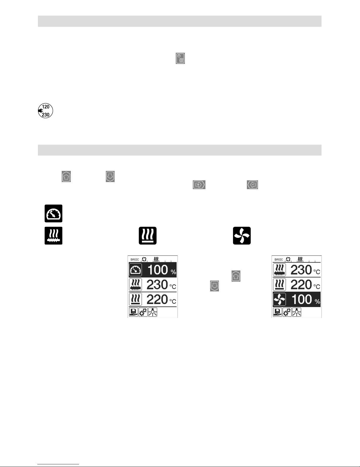
Einstellen eines Parameters
• Muss eine Sollwertvorgabe (z.B Soll- Plasttemperatur) verändert werden, kann durch Drücken der Tasten 21 / 22
«Auf»
oder «Ab» der entsprechende Sollwert ausgewählt werden. Solange der Sollwert markiert
dargestellt wird, kann er über die Tas te n 24 / 2 6 «Plus»
oder «Minus» verändert werden. Beim
WELDPLAST S1 sind vier Sollwerte einstellbar:
Ausstossmenge (max. Ausstoss wenn Potentiometer auf Stufe 5 steht, bzw. auf 100% eingestellt ist).
Plastifizier-Temperatur Luft-Temperatur Luftmenge
• In der Arbeitsanzeige können
max. drei Elemente dargestellt
werden.
• Weitere Elemente werden
durch Drücken der Tasten
21 / 22 «Auf»
oder
«Ab»
erreicht.
• Die Ausstossmenge kann während dem Extrudieren direkt über das Potentiometer (3) in 5 %-Schritten
verstellt werden. Der Bereich geht dabei von min. 35 % bis zur max. eingestellten Ausstossmenge.
Der aktuell eingestellte Wert ist dabei immer in der Arbeitsanzeige sichtbar.
Der in der Arbeitsanzeige eingestellte Wert ist als Maximum-Wert zu verstehen. Mit dem Potentiometer (3)
kann nur bis zu diesem eingestellten Maximum-Wert eingestellt werden. Typischerweise ist dieser deshalb auf
100 % eingestellt.
• Ist die Ausstossmenge mit dem minimalen Ausstoss (35 %) zu gross, muss auf die Schweissdrahtdicke 3 mm
gewechselt werden.
• Ist die Ausstossmenge mit dem maximalen Ausstoss (100 %) zu klein, muss auf die Schweissdrahtdicke 4 mm
gewechselt werden.
13
Select Profile (Profilauswahl)
• Auswahl eines vordefinierten oder freien Profils
• Der WELDPLAST S1 verfügt über sechs vordefinierte Leister-Profile und bis zu zehn frei definierbare Profile:
Schweissprofile
Max. Ausstoss
[%]
Soll- Plastifizier-
Temperatur
[°C / °F]
Soll- Luft-
Temperatur
[°C / °F]
Luftmenge
[%]
1 BASIC einstellbar einstellbar einstellbar einstellbar
2 PE-HD 100 230 260 100
3 PP 100 240 260 100
4 PVC-U 100 200 300 100
5 PVDF 100 250 320 100
6 – 16 freie Profile einstellbar einstellbar einstellbar einstellbar
• Durch die Auswahl des Symbols
in der Funktionsanzeige (27) gelangen Sie in das Menü «Select Profile».
Eines dieser sechs vordefinierten (1 – 6) oder ein kundenspezifisches freies Profil (7 – 16) kann mit den
Tasten 21/ 22 «Auf»
und «Ab» ausgewählt werden.
• Werden Sollwerte (Profile 2 – 16) während dem Betrieb verändert, werden diese nicht im Profil gespeichert !
• Wird die Maschine aus- / eingeschaltet, erscheinen immer wieder die im Profil definierten Werte.
• Möchten Sie beim Wiedereinschalten der Maschine die zuletzt eingestellten Werte benützen, müssen Sie das
Profil BASIC (1) auswählen.
• Das aktuell ausgewählte Profil ist links in der Statusanzeige «Bereich 1» (29) sichtbar.
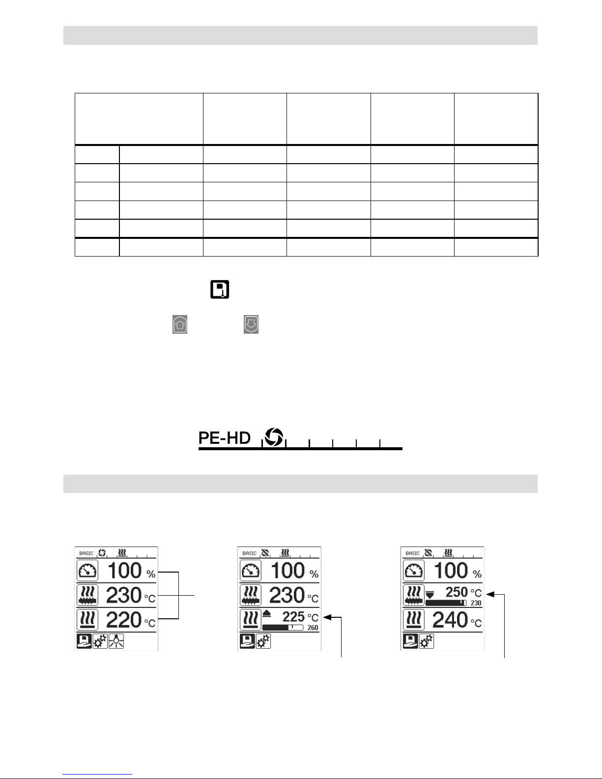
Überwachung der Schweissparameter
• Die aktuelle Plastifizier- und Luft-Temperatur wird ständig überwacht. Weicht ein Istwert vom entsprechenden
Sollwert ab, wird dies in der Arbeitsanzeige (28) angezeigt («Show Set Values» nicht aktiviert).
• Istwert entspricht
dem Sollwert.
• Istwert Luft-Temperatur zu tief.
Aufheizvorgang wird blinkend
signalisiert (Pfeil nach oben
und Fortschrittsbalken).
• Istwert Plastifizier-Temperatur
zu hoch.
Abkühlvorgang wird blinkend
signalisiert (Pfeil nach unten
und Fortschrittsbalken).
28
14
Freigabe Antrieb
• Für die Freigabe des Antriebs gibt es vier verschiedene Wartezeiten (siehe Tabelle). Diese sind von der
Ist-Plastifizier-Temperatur sowie von der eingestellten Soll-Plastifizier-Temperatur abhängig. Die Vorwärmluft
hat keinen Einfluss auf die Freigabe des Antriebs.
• Die Freigabezone beginnt, sobald die Ist-Plastifizier-Temperatur grösser als die Solltemperatur – 20 K ist.
• Zugehöriges Symbol in der Statusanzeige:
Antrieb ist nicht freigegeben Antrieb freigegeben
Ist-Plastifizier-Temperatur beim
Einschalten der Heizung oder verstellen
der Soll-Plastifizier-Temperatur
SollPlastifizierTemperatur
Freigabezeit nach
Erreichen der
Freigabezone
Soll-Plastifizier-Temperatur – 5K
< Ist-Plastifizier-Temperatur
—
Antrieb wird direkt
freigegeben
Soll-Plastifizier-Temperatur – 20K
< Ist-Plastifizier-Temperatur
< Soll-Plastifizier-Temperatur – 5K
— 30 sek.
Soll-Plastifizier-Temperatur – 20K
> Ist-Plastifizier-Temperatur
(Unterhalb der Freigabezone)
> 190°C 2 min. 30 sek
Soll-Plastifizier-Temperatur – 20K
> Ist-Plastifizier-Temperatur
(Unterhalb der Freigabezone)
< 195°C 3 min. 30 sek
• Kann der WELDPLAST S1 die Ist-Plastifizier-Temperatur bei freigegebenem Antrieb für mehr als 10 sek. nicht in
der Freigabezone halten, wird der Antrieb wieder gesperrt. Sobald das Gerät die Freigabezone wieder erreicht
hat, wird der Antrieb nach einer in der Tabelle definierten Zeit wieder freigegeben.
Netzunterbruch
Zustand Antrieb vor
Netzunterbruch
Dauer
Netzunterbruch
Zustand WELDPLAST S1
nach Netzunterbruch
Antrieb freigegeben
Arbeitsanzeige Schweissen
≤ 5 sek
Das Gerät startet ohne Wiederanlaufschutz auf
und wechselt direkt in den Zustand vor dem
Netzunterbruch
Antrieb freigegeben
(Vorwärmluft > 100 °C)
> 5 sek
Das Gerät wechselt direkt in den
«Cool down modus»
Antrieb freigegeben
(Vorwärmluf t < 100 °C)
> 5 sek
Das Gerät startet und auf dem Display (5)
erscheint die Startanzeige.
• Durch gleichzeitiges Drücken von mindestens zwei Sekunden der Tasten 21 / 22 «Auf»
und «Ab»
wird die Tastensperre aktiviert bzw. deaktiviert.
Tastensperre

15
Eingabe von Namen oder Passwörtern
• Über den Tastaturmodus können Namen definiert oder Passwörter mit maximal 12 Zeichen eingegeben werden.
Tastaturmodus Zeichenauswahl Symbolauswahl
Auf (21)
Ab (22)
Vertikale Zeichenauswahl
Minus (24)
Plus (26)
Horizontale Zeichenauswahl Auswahl der Symbole
Bestätigen (25)
Das ausgewähltes Zeichen
bestätigen
Das ausgewähltes Symbol
bestätigen
Wechsel zwischen Gross- und Kleinschreibung
Cursorposition im Namen verschieben
Leerschlag einfügen
Löschen eines einzelnen Zeichens (Zeichen links von Cursor)
Durch Auswählen dieses Symbols Wechsel auf
Funktionsanzeige
27
27
34
35
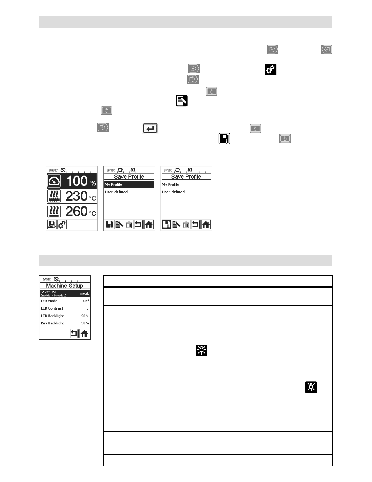
Profile definieren
• Im Menü «Save Profile» können Sollwerteinstellungen der max. Ausstossmenge, Plastifizier- Luft-Temperatur
und Luftleistung unter einem von Ihnen gewünschten Namen abspeichert werden (siehe Kapitel «Eingabe von
Namen oder Passwörtern»).
• Erstellen eines neuen Profils:
– In der Arbeitsanzeige (28) gewünschte Sollwerte mittels Tasten 24 / 26 «Plus»
oder «Minus»
einstellen.
– In der Funktionsanzeige (27) mit Taste 26 «Plus»
das Menü Einstellungen auswählen.
– Im Menü «Setup» die Auswahl mit Taste 26 «Plus»
«Save Profile» auswählen.
– Das Profil «User-defined» auswählen und mittels Taste (25)
bestätigen.
– In der Funktionsanzeige (27) das Symbol
«Ausgewählte Position bearbeiten» auswählen und
mittels Taste (25) bestätigen.
– Gewünschten Profilnamen eingeben (siehe Kapitel «Eingabe von Namen oder Passwörtern»), anschliessend
mit der Taste 26 «Plus»
das Symbol auswählen und mittels Taste (25) bestätigen.
– In der Funktionanzeige (27) ausgewähltes Symbol «Speichern» mittels Taste (25) bestätigen. Das
Profil wurde erfolgreich gespeichert und ausgewählt.
3534
16
Profile definieren
• Editieren eines bestehenden Profils (ausgenommen Leister-Profile):
– In der Arbeitsanzeige (28) gewünschte Sollwerte mittels Tasten 24 / 26 «Plus»
oder «Minus»
einstellen.
– In der Funktionsanzeige (27) mit Taste 26 «Plus»
das Menü Einstellungen auswählen.
– Im Menü «Setup» die Auswahl mit Taste 26 «Plus»
«Save Profile» auswählen.
– Das zu editierende Profil auswählen und mittels Taste (25)
bestätigen.
– In der Funktionsanzeige (27) das Symbol
«Ausgewählte Position bearbeiten» auswählen und
mittels Taste (25) bestätigen.
– Gewünschter Profilnamen eingeben (siehe Kapitel Eingabe von Name oder Passwörter), anschliessend mit
Taste 26 «Plus»
das Symbol auswählen und mittels Taste (25) bestätigen.
– In der Funktionanzeige (27) ausgewähltes Symbol «Speichern» mittels Taste (25) bestätigen. Das
Profil wurde erfolgreich gespeichert und ausgewählt.
Maschinen-Einstellungen
Menü Funktion
Select Unit
Einstellung der verwendeten Einheit:
– metrisch / imperial
LED Mode
LED Modus:
– ON*: Die LED-Beleuchtung kann nur eingeschaltet werden,
wenn der Antrieb freigegeben ist. Sobald der Antrieb freigegeben ist, erscheint in der Funktionszanzeige (27) das
LED-Symbol
. Über dieses kann die LED-Beleuchtung nach
Wunsch ein- / ausgeschaltet werden. Der LED-Modus wird nicht
verändert.
– ON: Die LED-Beleuchtung ist immer eingeschaltet.
In der Funktionszanzeige (27) wird das LED-Symbol
eingeblendet. Über dieses kann die LED nach Wunsch
ein- / ausgeschaltet werden.
Der LED-Modus wird nicht verändert.
– OFF: Die LED-Beleuchtung ist immer ausgeschaltet.
LCD Contrast Einstellen des LCD-Kontrastes
LCD Backlight Einstellen der Display-Hintergrundbeleuchtung
Key Backlight Einstellen der Tastatur-Hintergrundbeleuchtung
17
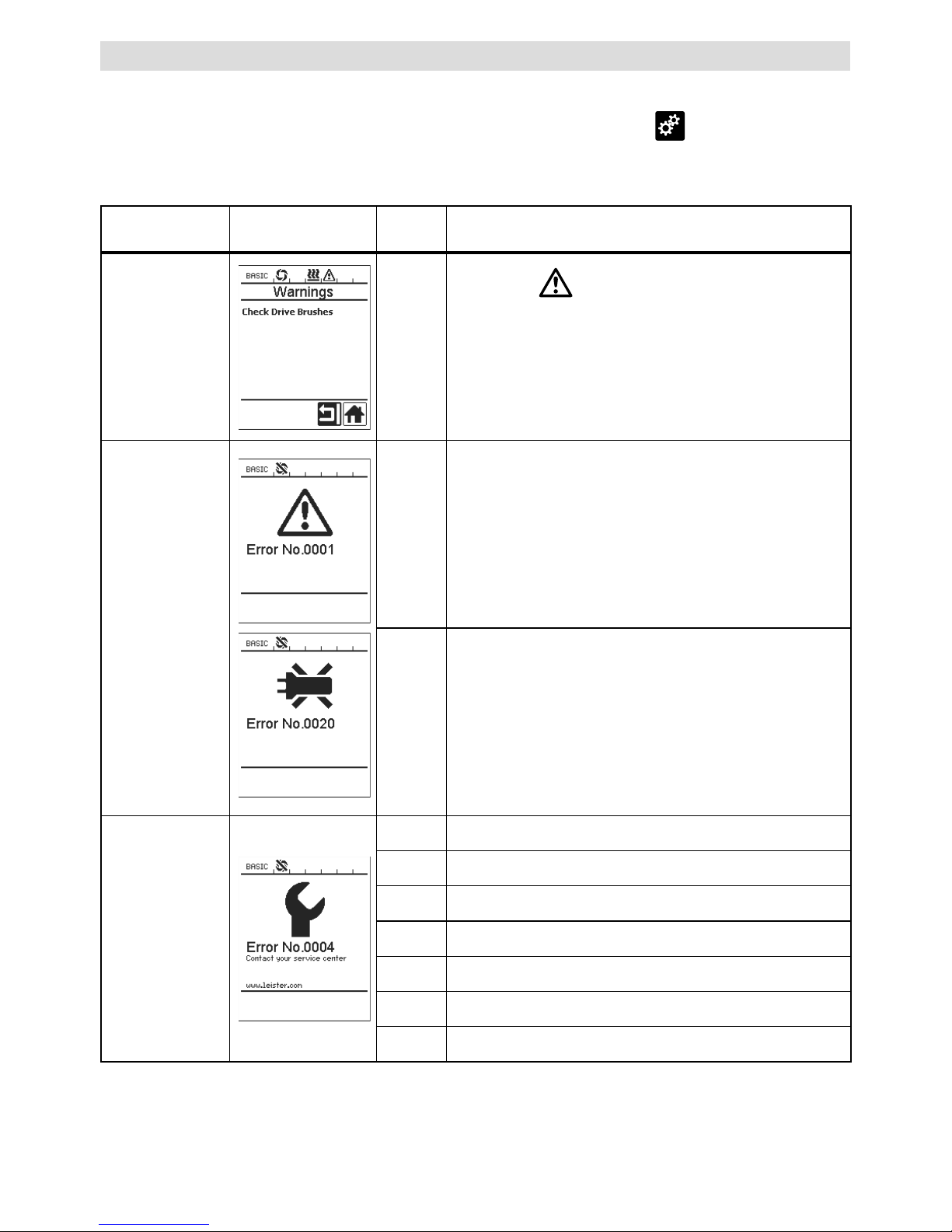
Warnung und Fehlermeldungen
• Liegt eine Warnung vor, kann der Anwender ohne Einschränkung weiter arbeiten. Genauere Informationen
zur Warnung können über die Funktionsanzeige (27) im Menü Einstellungen
unter «Show Warnings»
abgerufen werden.
• Tritt ein Fehler auf, schaltet das Gerät alle Heizungen aus und der Antrieb wird nicht mehr freigegeben.
Art der
Meldung
Anzeige
Feler-
Code
Fehlerbeschreibung
Warnung
—
Warnsymbol
in der Statusanzeige (30).
Die Kohlenbürsten des Antriebs müssen gewechselt
werden.
Nach dem ersten Erscheinen des Warnsymbols kann der
Antrieb noch für 5 h betrieben werden. Anschliessend
erscheint die Fehlermeldung «Error No.0400» und der
Antrieb wird nicht mehr freigegeben.
Fehler
0001
Übertemperatur des Gerätes.
Gerät abkühlen lassen.
0020 Heizelement für Luft defekt.
Fehler !
Leister Service
Center
kontaktieren
0004 Fehler der Hardware.
0008 Thermoelement der Luft defekt.
0010 Thermoelement des Plast defekt.
0040 Heizelement des Plast defekt.
0100 Gebläse defekt.
0200 Fehler Kommunikation.
0400 Kohlenbürsten / Antrieb oder Übertemperatur Antrieb.
18
Verbrennungsgefahr!
Nur mit temperaturfesten Handschuhen arbeiten.
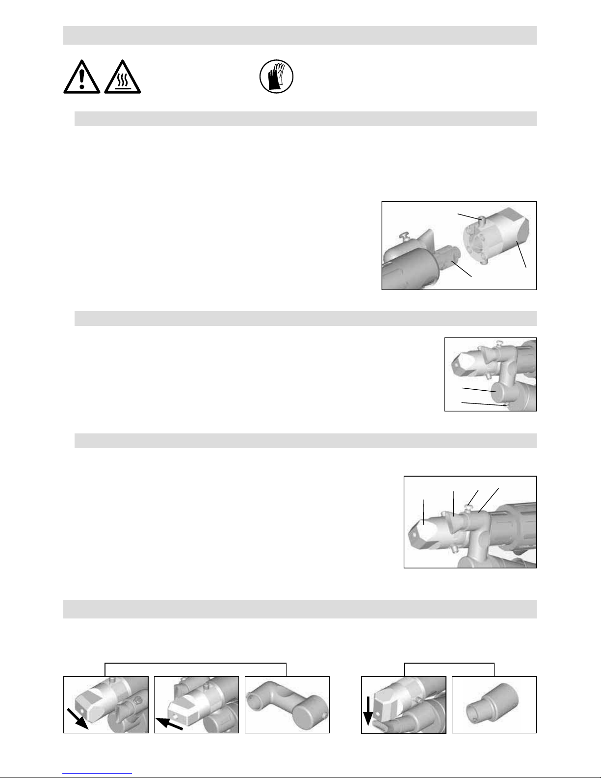
Wechsel des Schweissschuhs
• Demontage
– Das betriebswarme Gerät abschalten und vom elektrischen Netz trennen.
– Den Schweissschuh (8) durch Lösen der Klemmschrauben (18) von der Extrudierdüse (17) entfernen.
– Die Extrudierdüse (17) bei jedem Schweissschuhwechsel von
Schweissgutrückständen reinigen und sicherstellen, dass sie
festgeschraubt ist.
• Montage
– Einen der Schweissnaht angepassten Schweissschuh (8) auf die
Extrudierdüse (17) schieben und durch Anziehen der Klemmschrauben (18) be fes tigen.
18
8
17
Wechsel der Vorwärmdüse
• Demondage
– Bei der Vorwärmdüse (9) die Klemmschraube (19) lösen und
Vorwärmdüse (9) von der Heissluftführung (16) abziehen.
• Montage
– Vorwärmdüse (9) auf die Heissluftführung (16) schieben.
Auf parallele Ausrichtung zum Schweissschuh (8) achten.
– Klemmschraube (19) anziehen.
8
9
19 16
Wechsel der Heissluftführung
• Demontage
– Klemmschraube (33) lösen. Heissluftführung (16) kann abgezogen oder in
die gewünschte Schweissrichtung gedreht werden.
– Entsprechende Heissluftführung (16) montieren (siehe Kapitel Schweissrichtung).
– Klemmschraube (33) festziehen.
Schweissrichtung
Schweissrichtung Heissluftführung Schweissrichtung Heissluftführung
Wechsel von Zubehör
• Für die ausgewählte Schweissrichtung die passende Heissluftführung.
33
16
19
• Aus technischen und sicherheitsrelevanten Gründen darf ausschliesslich nur Leister-Zubehör verwendet werden.
• Zuberhör unter www.leister.com
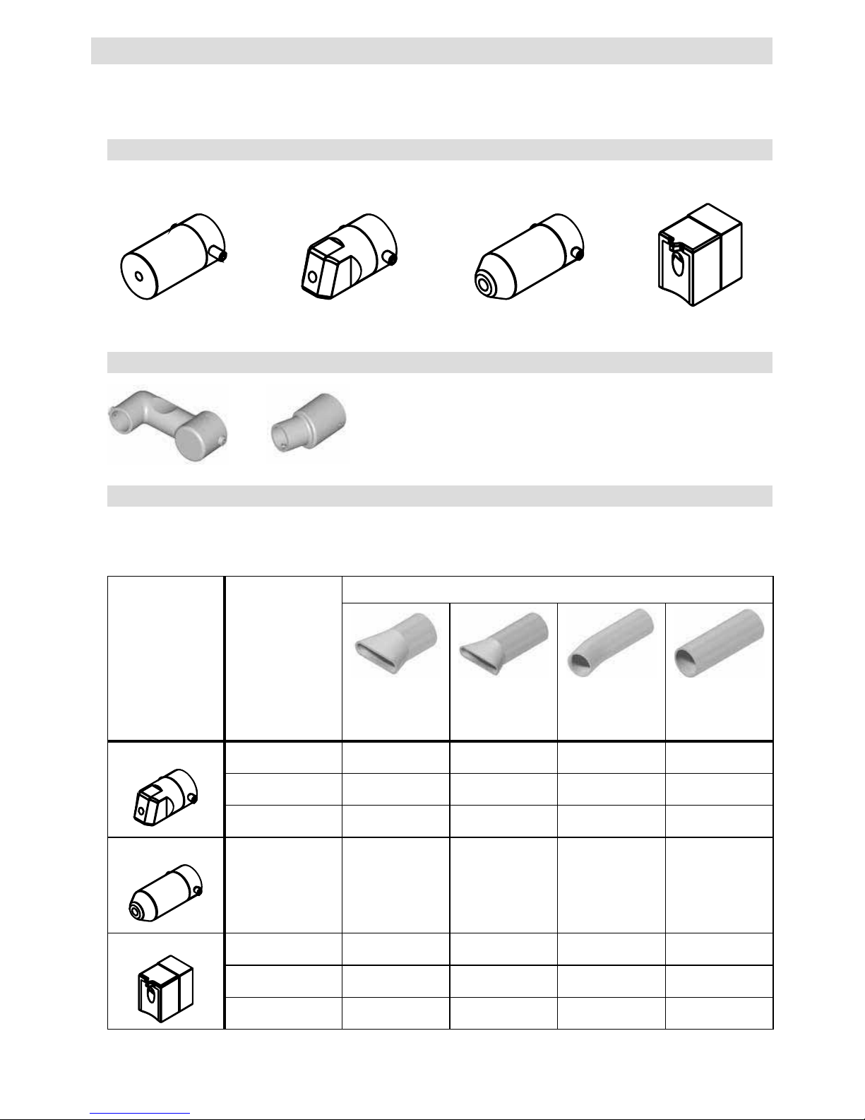
Zubehör
Vorwärmdüse
• Damit bei der grossen Auswahl an Schweissschuhen eine optimale Vorwärmung erreicht wird, bietet Leister
Technologies AG verschiedene Vorwärmdüsen an.
Schweissschuh
Schweissnahtbreite
mm
Vorwärmdüsen
Breite 21 mm
Länge 26 mm
Breite 21 mm
Länge 42 mm
ø 14 mm
Länge 58 mm
abgewinckelt
ø 14 mm
Länge 46 mm
Kehlnaht
5 / 6
• (b) •
8 / 10
• (b) •
12
• (b) •
Ecknaht
• (b) •
V-Naht
3 / 4
•• (a)
5 / 6
•• (a)
8 / 10
•• (a)
Schweissschuh-Sortiment
• Leister Technologies AG bietet für alle gebräuchlichen Nahtformen entsprechende Schweissschuhe in diversen
Grössen an
:
Rohling
Kehlnaht
Ecknaht V-Naht
a) DVS-Schweissschuhe analog WELDPLAST S2-PVC.
b) Abgewinckelte Vorwärmdüse für optimale Vorwärmung bei radialen Rohrschweissungen.
Heissluftführung
20
• Netzanschlussleitung (13) und Stecker auf elek
trische und mechanische Beschädigungen überprüfen.
• Die Extrudierdüse (17) bei jedem Schweissschuhwechsel von Schweissgutrückständen befreien.
Wartung
• Reparaturen sind ausschliesslich von autorisierten Leister-Service-Stellen ausführen
zu lassen.
Diese gewährleisten innert 24 Stunden einen fachgerechten und zuverlässigen
Reparatur-Service mit Original-Ersatzteilen gemäss Schaltplänen und Ersatzteillisten.
• Erscheint beim WELDPLAST S1 nach dem Einschalten des Gerätes die Anzeige
«Maintenacne servicing», sollte der Antriebsmotor (Kollektor und Kohlenbürsten) von
einer autorisierten Leister-Service-Stelle kontrolliert und allenfalls ersetzt werden. Die Anzeige verschwindet automatisch nach 10 Sekunden oder kann durch
Drücken der Taste (25) «Bestätigen» direkt übersprungen werden.
Service und Reparatur
• Für dieses Gerät gelten die vom direkten Vertriebspartner/Verkäufer gewährten Garantie- oder Gewährleistungsrechte ab Kaufdatum. Bei einem Garantie- oder Gewährleistungsanspruch (Nachweis durch Rechnung oder
Lieferschein) werden Herstellungs- oder Verarbeitungsfehler vom Vertriebspartner durch Ersatzlieferung oder
Reparatur beseitigt. Heizelemente sind von der Gewährleistung oder Garantie ausgeschlossen.
• Weitere Garantie- oder Gewährleistungsansprüche werden im Rahmen des zwingenden Rechts ausgeschlossen.
• Schäden, die auf natürliche Abnutzung, Überlastung oder unsachgemässe Behandlung zurückzuführen sind,
werden von der Gewährleistung ausgeschlossen.
• Keine Garantie- oder Gewährleistungsansprüche bestehen bei Geräten, die vom Käufer umgebaut oder verändert
wurden.
Gewährleistung

21
Operating Instructions (Translation of the original operating instructions)
Read the operating instructions carefully before starting
the device and keep them for future reference.
Leister WELDPLAST S1
Extrusion Welder
Application
• Extrusion welding of the following materials:
PP / PE-HD / PVC-U / PVC-C / PVDF
• Other materials on enquiry
Warning
Opening the device is extremely dangerous, since live parts and connections are exposed.
Remove the plug from the socket before opening the device.
Danger of fire and explosion if the extrusion welder is used incorrectly (e.g. overheating
of material), particularly near combustible materials and explosive gases.
Danger – can cause burns ! Do not touch bare metal parts and emerging material while
hot. Allow the device to cool. Do not direct stream of hot air or emerging material towards
people or animals.
Connect device to power socket with protective earth conductor. Any break in the
protective earth conductor inside or outside the device is dangerous!
Only use extension cables with a protective earth conductor!
Caution
The nominal voltage indicated on the device must correspond to the mains voltage. If
power failure occurs, the main switch and drive must be switched o (release locking
device).
When using the device on building sites, a residual current circuit breaker is essential
for the safety of persons there.
Risk of dazzling! Avoid direct eye contact with the LED light beam.
The device must not be left unattended when in use. Heat can reach combustible
materials which are out of sight.
The device may only be used by trained personnel or under their supervision. Children
may not use the device under any circumstances.
Keep away from wet and damp areas.
GB
22
Voltage V~ 100 120 230
Power consumption W 1500 1800 1600
Frequency Hz 50/60 50/60 50/60
Air temperature °C max. 360
Plasticizing temperature °C max. 260
Output (Ø 3 mm) kg/h HD-PE 0.2 – 0.5; PP 0.2 – 0.5
Output (Ø 4 mm) kg/h HD-PE 0.3 – 0.8; PP 0.3 – 0.75
Filler rod mm Ø 3 / Ø 4
Emission level L
pA
(dB) 76 (K = 3 dB)
Dimensions L × w × h mm 435 × 264 × 91 (without welding shoe)
Weight kg 4.7 (without power supply cord)
Conformity mark
Mark of approval
Protection class I
The right to make technical changes is reserved
Conformity
Leister Technologies AG, Galileo-Strasse 10, CH-6056 Kaegiswil/Switzerland confirms that this product
in the version put into circulation by us, fulfils the requirements of the following EC directives.
Directives: 2006/42, 2004/108, 2006/95, 2011/65
Harmonised standards: EN 12100, EN 55014-1, EN 55014-2, EN 61000-6-2, EN 61000-3-2,
EN 61000-3-3, EN 62233, EN 60335-2-45, EN 50581
Kaegiswil, 20.10.2014
Bruno von Wyl, CTO Andreas Kathriner, GM
Disposal
Power tools, accessories and packaging should be recycled. For EU countries only: do not
dispose of power tools in your household rubbish! According to the European Directive 2002/96
on waste electrical and electric equipment and its implementation in national law, power tools
which can no longer be used must be collected separately and recycled.
Technical Data
23
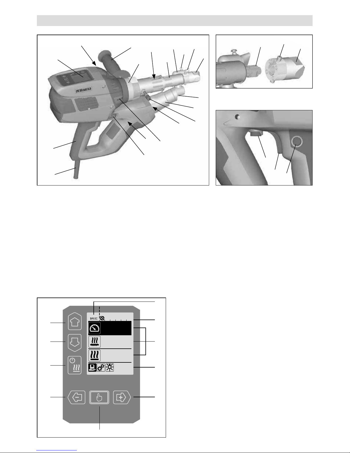
Device Description
1 Main switch
2 On/o switch for drive
3 Potentiometer
4 Drive locking device
5 Display
6 Guide handle
7 Jacket heating
8 Welding shoe
9 Pre-heating nozzle
10 Protection tube
11 Filler rod insertion point
12 Device grip
Operating unit
21 Key «Up»
22 Key «Down»
23 Key heating «on / o»
24 Key «Minus»
25 Key «Confirmed»
26 Key «Plus»
Display
27 Function display
28 Working display
29 Status display «Section 1»
30 Status display «Section 2»
13 Power supply cord
14 Heating element protection tube
15 Blower (brushless)
16 Hot air duct
17 Extruder nozzle
18 Clamping screw welding shoe
19 Clamping screw pre-heating nozzle
20 Gripper clamp
31 LED light
32 Buer bolt
33 Clamping screw hot air guidance
2
3
4
18
8
17
%
100
°C
230
°C
260
25
28
30
27
26
21
22
23
24
29
1
5
6
7
8
19
10
11
12
13
14
15
16
20
9
31
11
32
33
24
Operating unit description
Display description
Status display «Section 1» (29)
PE-HD
Profile currently selected. If profile names consist of more than 6 characters, the first 6 characters
are shown first, followed by the remaining characters.
1m16s Time remaining until the drive is released (1 min. 16 sec.)
Status display «Section 2» (30)
Drive released
Drive not released
Warning (carbon brushes / drive)
Key lock (only appears when key lock is activated)
Air and plasticizing heating is switched on
Keyboard mode
Current selection in the working
display
Current selection in the function
display
Up (21)
Down (22)
Changes the item within the working display
Changes from the function display
to the working display
Heating
on/o (23)
No function
Changes from welding mode to the
cooling process
Changes from the cooling process
to welding mode
Changes from the start display to
welding mode
Minus (24)
Plus (26)
(press briefly)
Sets the required setpoint in 5°C or
5% stages.
Changes the item in the function
display
Minus (24)
Plus (26)
(press and hold)
Sets the required setpoint in 10°C
or 10% stages.
Changes the item in the function
display
Confirmed (25)
Set value is adopted straight away
and the selection goes straight back
to the function display
Selected function is executed
25
Function and working display
• On the function and operating display, the field or icon
that is highlighted always indicates what is currently
selected.
• The actual values are always shown in the working
display, unless an item is selected, in which case the
setpoint is displayed.
• If «Show Set Values» is activated, both the actual
value and the setpoint are displayed (small font size).
Function display (27)
Select freely definable and predefined
profiles
Settings
Return to working display
(exits a menu directly)
Switch LED on/o.
This function is only available if the LED
has been activated.
Go back one level
Reset settings or hour counter
Service menu
(can only be accessed by entering the
password)
Save
Delete the selected item
Edit the selected item
Start cooling process
Function display (28)
Setpoint:
Drive output volume [%]
Setpoint:
Plasticizing temperature [°C/°F]
Setpoint:
Air temperature [°C/°F]
Setpoint:
Air volume [%]
Information box
°C
200
230
The arrow pointing upward and the
progress bar indicate that the setpoint
(shown on the progress bar) has not yet
been reached (too cold). The flashing
value is the actual value. The value
next to the progress bar is the setpoint.
°C
250
230
The arrow pointing downward and the
progress bar indicate that the setpoint
(shown on the progress bar) has not yet
been reached (too hot). The flashing
value is the actual value. The value
next to the progress bar is the setpoint.
°C
250
230
If «Show Set Values» is activated,
both the actual temperature (large font
size) and the set temperature (small
font size) are displayed.
Cooling process
Device in standby mode. Once the
counter has counted down, the device
will start «Cool down mode».
An error has occurred. An error code
also appears (the device is no longer
ready for use). Contact an authorized
service center.
Heating element air faulty
Device temperature too high.
Allow the device to cool down.

26
Welding startup display
Display during the heating
process
Select Profile
Select a user-defined profile
or one defined by Leister. The
process of selecting a profile
is described in detail in the
«Select Profile» chapter on
page 32.
Setup
In the basic setting, you can
save profiles and access
the standby function via the
«Setup» menu.
Select «Advanced Mode»
to access a range of other
settings options.
Save profile
The process of saving freely
definable profiles is described
in detail in the «Defining
profiles» chapter on page
34/35.
Startup display
Display on startup with the
software release of the output
unit.
Cool down mode
In this mode, the heating is
switched o and the device
is in cool down mode. If the
pre-heating air temperature
is more than 100°C when
the device is switched
on, the device switches
automatically to «Cool down
mode». The cooling process is complete when
the pre-heating air temperature has been below
100°C for 2 mins.
To switch the heating back on again, press the
«Heating on/o» key (23)
or the «Confir-
med» key (25) .
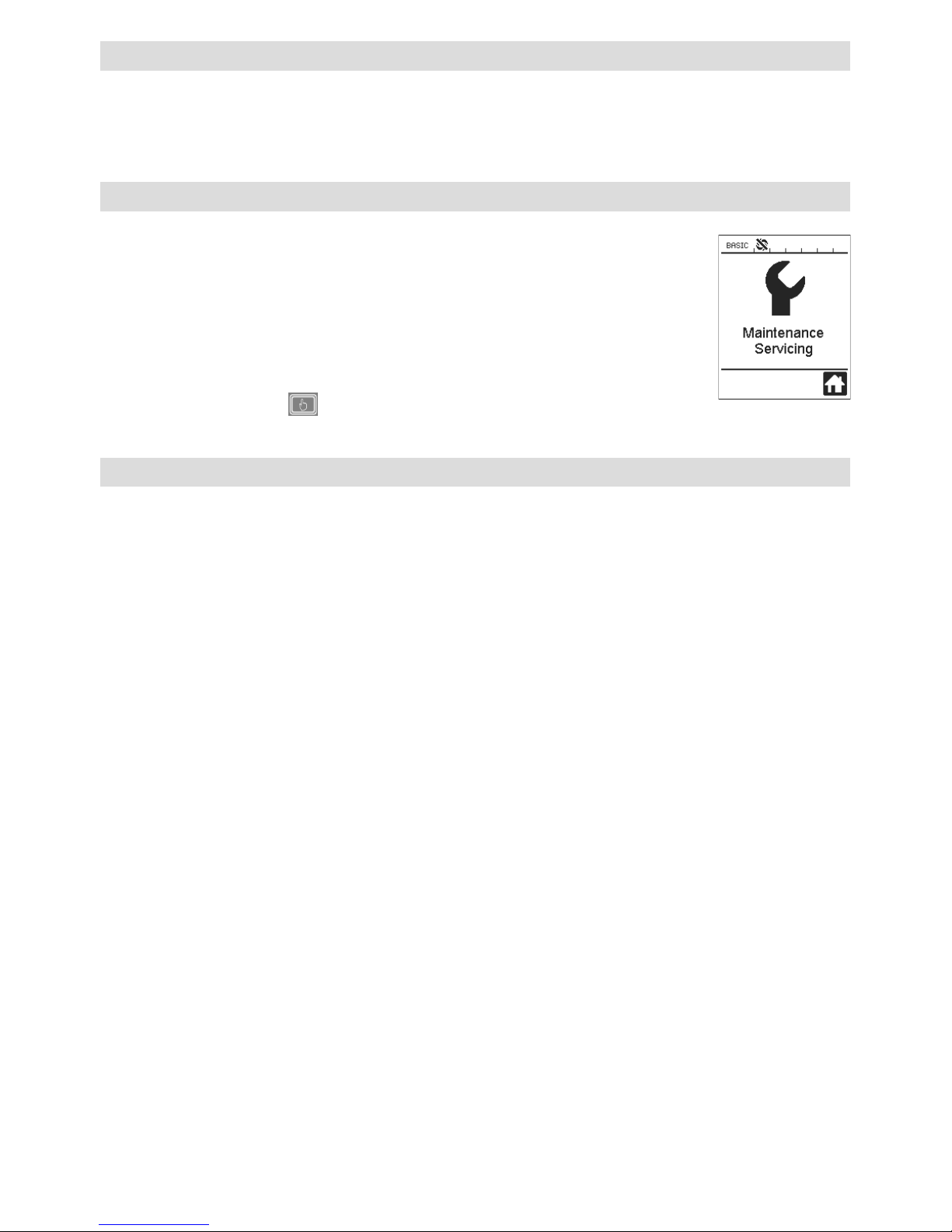
Maintenance servicing
When the maintenance
interval for the drive motor
is reached, «Maintenance
Servicing» appears after
the startup display.
You can
carry on working by pressing
the
«Confirmed» key (25)
. You must take the
device to your service center.
Start display
The start display shows all
setpoints.
At this point, the heating is
not switched on but you can
set all setpoints.
Working display overview
27
Working display overview
Standby
If standby mode is activated
and the user does not press
a key on the operating unit or
the on/o switch for drive
(2) during the time set as
the «Standby Interval», the
device automatically switches
to the standby display. If
the user does not press the
«Confirmed» key (25)
in the next 180 seconds, cool
down mode starts automatically.
Duty Info
Hours Drive: Current runtime
of the drive (can be reset).
Hours Blower: Current runtime of the blower.
Hours Machine: Current
runtime of the machine.
General Info
Firmware HMI: Software
version of the display unit
(communication module).
Firmware Machine: Software
version of the output unit.
Production Info: Information
about the production date.
Warnings
If there is a warning pending,
this is indicated by the
symbol in the status
display. The «Warnings»
menu contains more detailed
information about the current
warning.
Machine Setup
The machine settings are
described in detail in the
«Machine Setup» chapter.
Application Mode
If „Application Mode“ is
activated, the operating
display will provide detailed
information on the actual
plasticizing temperature
and the capacity utilization
of the hot-air blowers and
plasticizing heating.
Plast : 80 % 222 °C
Heat : 40 % 197 °C
Amb. : 25 °C
Mains : 50 Hz
If «Show Set Values» is
activated, both the actual
temperature (large font
size) and the set temperature (small font size) are
displayed.
Reset to defaults
If the “Reset to defaults”
menu is selected and
confirmed by selecting the
relevant function
,
all customer-specific profiles
will be deleted. Settings that
have been changed via the
Setup menu will be reset to
the factory settings.

28
Menu navigation
Only available in «Advanced Mode»
29
Risk of burning! Let the device cool
Work environment / Safety
Before putting into operation, check power supply cord (13) and connector as well as extension
cable for electrical and mechanical damages.
The extrusion welder must not be used in areas where there is danger of explosion or flammable
materials. Ensure a safe posture during work. The power cable and filler rod must be free to move
and must not obstruct the user or third parties during work.
Place extrusion welder on a fire resistant base. Hot metal parts and hot streams of air must be
kept at a safe distance from the base and walls.
Setting the guide handle
Workplace
1
2
3
1
Loosen clamp by turning
the guide handle (6) anticlockwise
2
Move the guide handle (6)
into the desired operating
position.
3
Tighten clamp again by turning
guide handle (6) clockwise
Leister provides a stand for
commissioning and holding
the extrusion welder
When not welding, the drive should be switched o with the drive on/o
switch (2).
Place the extrusion welder with correspondingly set and firmly tightened
guide handle (6) on a stable, fireproof base or buer bolt (32) as shown
in the illustration.
Guide handle
Removing/Fitting the handle
Removing the handle
1
Turn the handle (6) anticlockwise to loosen the clamp.
2
Press on the handle (6) and the gripper clamp (20) to open the lock
(see arrows). Remove the handle (6) using the gripper clamp (20).
To fit the handle, follow the steps in reverse order.
1 2
Lock
Handle (6)
Gripper clamp (20)
30
Extension cables
• Ensure the minimum cross-section when using extension
cables:
• The extension cable must be approved for the site of use (e.g.
in the open air) and marked correspondingly.
• When using a power unit for power supply, its nominal power
rating is: 2 × nominal power rating of the extrusion welder.
Length
[m]
Minimum cross-section
(at 100 – 230V~) [mm
2
]
Up to 19
2.5
20 – 50 4.0
• Switch the extruder on at the main switch (1). Depending on the pre-heating air temperature, either the startup
display or «Cool down mode» will appear on the display (5). Press the «Heating on/o» key (23)
to start
the heating process.
• If the device is ready for operation, the LED light (31) will switch on automatically (factory setting).
• Press the on/o switch for drive (2) to start the drive.
Starting the device
Connect the device to the nominal voltage. The nominal voltage specified on the device
must match the mains voltage.
• Install the relevant welding shoe (8), pre-heating nozzle (9), and hot air duct (16) if necessary (Changing
accessories, page 37).
• Insert the filler rod (ø 3 or 4 mm) into the filler rod insertion point (11).
• The filler rod is automatically drawn through the filler rod insertion point (11).
There must be no resistance when the rod is inserted.
CAUTION!
Always operate the device with the filler rod, but never feed the filler rod into both filler rod
insertion points at the same time.
• The speed at which the filler rod is drawn in can be set using the potentiometer (3).
• Pause the delivery of material using the on/o switch for drive (2).
• Direct the pre-heating nozzle (9) onto the area to be welded.
• Pre-heat the area to be welded with oscillating movements.
• Place the device on the prepared welding area and press the on/o switch for drive (2) again.
• Carry out a test weld according to the welding instructions from the material manufacturer and the national
standards or directives. Check the test weld.
• Adjust the temperature setting, output volume, and air volume as necessary (see "Setting the welding parameters" chapter, page 31).
• During a longer period of welding, the on/o switch for drive (2) can be kept in continuous operation using
the drive locking device (4).
CAUTION!
• PVC-U and PVC-C are processed in the menu of PVC-U.
• To prevent corrosion when processing PVC-U, PVC-C, ECTFE, PVDF etc., we recommend flushing the extrusion
welder with HD-PE when you have finished welding.
Welding process
 Loading...