

Leister VULCAN SYSTEM Operating Instructions Manual
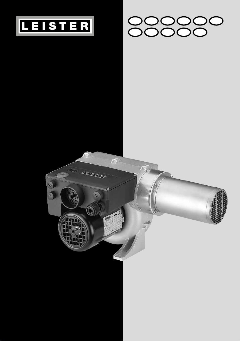
VULCAN
SYSTEM
®
GB I F E PD
TR CZ CN JS
Leister Technologies AG
Galileo-Strasse 10
CH-6056 Kaegiswil/Switzerland
Tel. +41 41 662 74 74
Fax +41 41 662 74 16
www.leister.com
sales@leister.com

Size 3
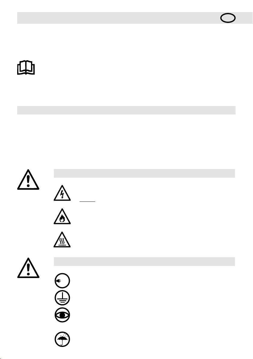
Wiring Diagram 4
Interface 5
FU / FC 6
D
Deutsch Bedienungsanleitung 7
GB
English Operating Instructions 16
I
taliano Istruzioni per l‘uso 25
F
Français Notice d’utilisation 34
E
Español Instrucciones de funcionamiento 43
P
Português Manual de instruções 52
S
Svenska Bruksanvisning 61
TR
Türkçe Kullanım Kılavuzu 70
Česky Návod k obsluze 79
CZ
中文 使用手册 88
CN
日本語 取扱説明書 98
J
2
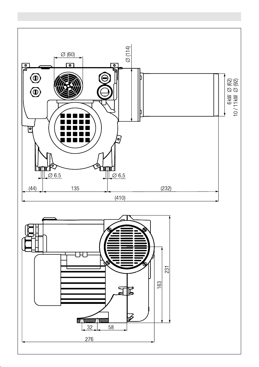
VULCAN SYSTEM Size mm
3
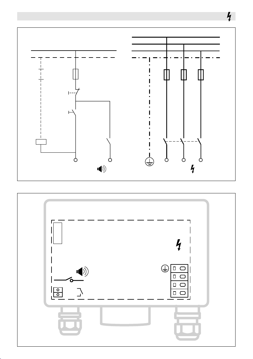
Wiring Diagram
P
N
L1
L2
L3
PE
K1
OFF
ON
Display
F1
max 3A
S1
S2
NO
Alarm
K1
COM
L1
Power
F2
K1
L2 L3
Power
Alarm
L3
COM
NO
4
L2
L1
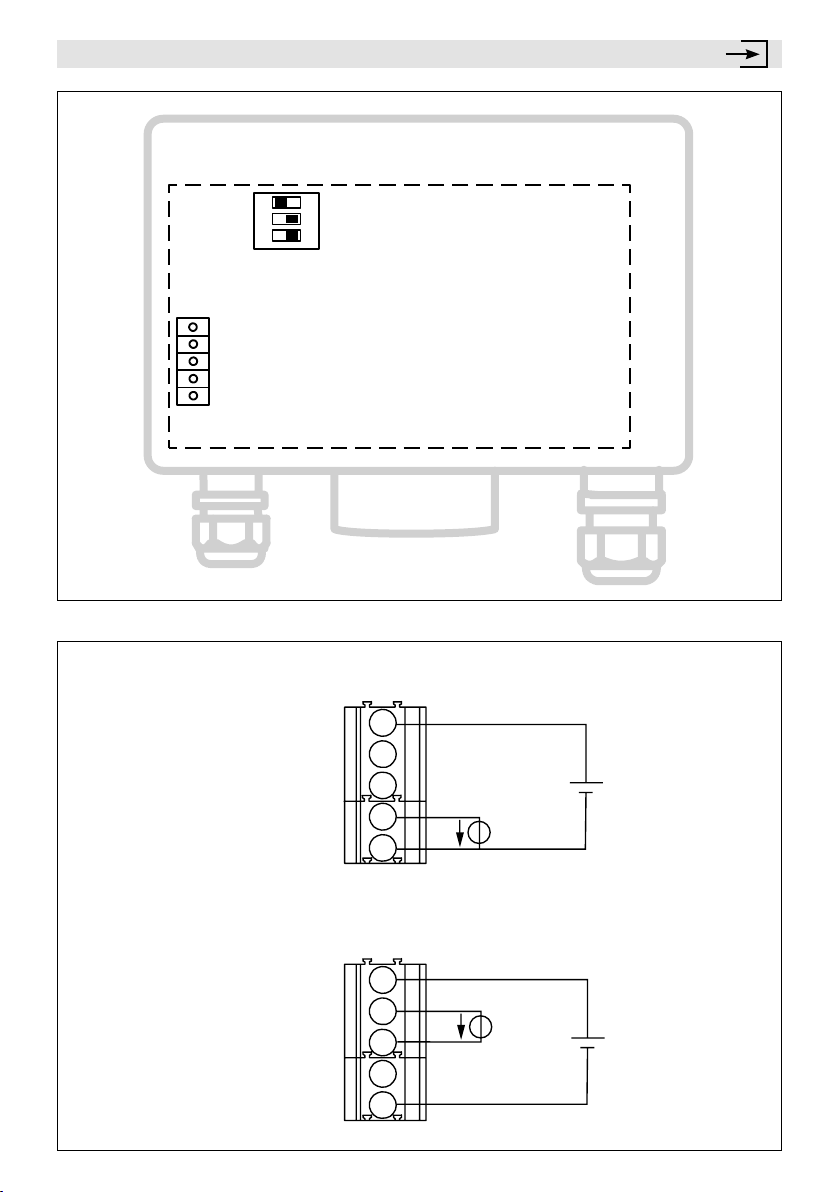
Interface
CLL
Interf
°F
Interface
24VDC
4–20mA4–20mA+
0–10VDC
GND
ON
Mode
3
2
1
OPL
Pot
°C
24VDC
4-20mA –
4-20mA +
0-10V
GND
24VDC
4-20mA –
4-20mA +
0-10V
GND
Input 0 – 10V
Us
Uc
Input 4 – 20mA
Ic
Us
5
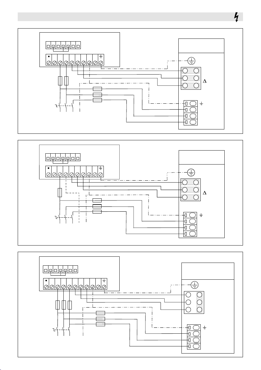
FU / FC Wiring Diagram
(4A)
(4A)
(4A)
FC 550
B1 B2 B3 B4 B5 B6 B7
L1 L2/N U V W PE PE
+
F1
S1
(32A)
L1
L2
Mains supply
Netzversorgung
3 x 230VAC
FC 550
B1 B2 B3 B4 B5 B6 B7
L1 L2/N U V W PE PE
+
F1
input: 1 × 230VAC
output: 3 × 230VAC
F2
L3
(16 -32A)
PE
input: 1 × 230VAC
output: 3 × 230VAC
Mains supply
Netzversorgung
3 x 230VAC
Mains supply
Netzversorgung
3 x 400VAC
Vulcan System
(3 x 230V)
U1
W2
Blower
L3
L2
L1
-
Blower
-
3 × 230V
Power
3
×
3 × 230V
V1
U2
W1 V2
Vulcan System
(3 x 400V)
U1
W2
V1
U2
W1 V2
230V
S1
(32A)
L1
L3
L2
Mains supply
Netzversorgung
3 x 400VAC
F2
(16 -32A)
PE
N
L3
Power
3
400V
L2
×
L1
Mains supply
B1 B2 B3 B4 B5 B6 B7
L3/N
L1 L2 U V W PE PE
+
F1
S1
(32A)
L1
L3
L2
Mains supply
Netzversorgung
3 x 400VAC or 3 x 480VAC
input: 3 × 400-480VAC
output: 3 × 400-480VAC
F2
(16 -32A)
PE
Netzversorgung
3 x 400VAC or 3 x 480VAC
Vulcan System
(3 x 400V or 3 x 480V)
U1
W2
V1
W1 V2
Blower
U2
Y- 3 × 400-480V
Power
L3
3
L2
3
L1
400V or
×
480V
×
6
Bedienungsanleitung
Wir gratulieren Ihnen zum Kauf eines VULCAN SYSTEM !
Sie haben sich für ein erstklassiges Heissluft-Gebläse aus dem Hause Leister entschieden, welches aus hochwertigen Materialien besteht. Jeder VULCAN wird einer strengen Qualitätskontrolle unterzogen, bevor er das Werk in
der Schweiz verlässt.
D
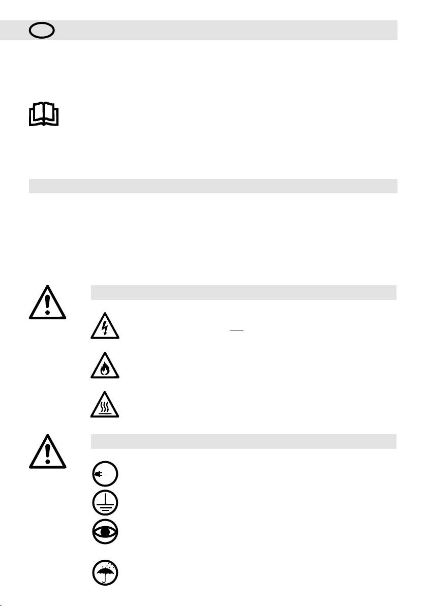
Bedienungsanleitung vor Inbetriebnahme aufmerksam
lesen und zur weiteren Verfügung aufbewahren.
Heissluft-Gebläse
VULCAN SYSTEM
Anwendung
Das Heissluft-Gebläse VULCAN SYSTEM eignet sich für den Einbau in Maschinen, Anlagen oder Geräte und ist
für den Dauerbetrieb ausgelegt.
Seine wichtigsten Anwendungen sind zum Beispiel Trocknen und Aufheizen, Auftauen, Beschleunigen und
Auflösen, Sterilisieren, Glätten, Glänzen, Aktivieren und Lösen, Trennen und Verschmelzen, Schrumpfen, Entfernen.
Warnung
Lebensgefahr beim Önen des Gerätes, da spannungsführende Komponenten
und Anschlüsse freigelegt werden. Vor dem Önen des Gerätes muss dieses
allpolig vom Netz getrennt werden.
Vorsicht
230
400
Feuer- und Explosionsgefahr bei unsachgemässem Ge brauch von Heissluft-
geräten, besonders in der Nähe von brennbaren Materialien und explosiven Gasen.
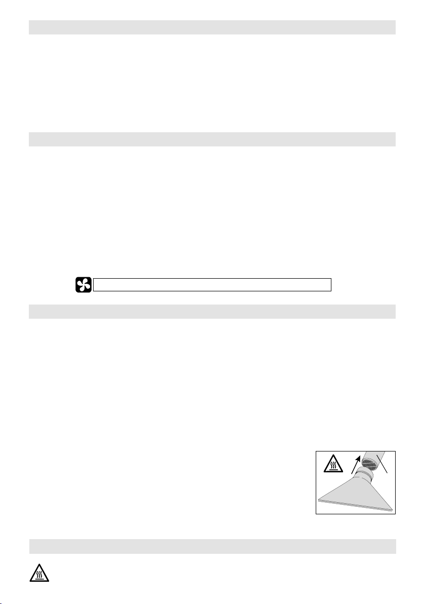
Verbrennungsgefahr! Heizelementrohr und Düse nicht in heissem Zustand
berühren. Gerät abkühlen lassen.
Heissluftstrahl nicht auf Personen oder Tiere richten.
Nennspannung, die auf dem Gerät angegeben ist, muss mit der Netzspannung
übereinstimmen. EN 61000-3-11; Z
Elektrizitäts-Versorgungs-Unternehmen konsultieren.
Gerät der Schutzklasse I muss mit Schutzleiter geerdet werden.
Gerät muss beobachtet betrieben werden.
Wärme kann zu brennbaren Materialien gelangen, die sich ausser Sichtweite
befinden. Gerät darf nur von ausgebildeten Fachleuten oder unter deren Aufsicht
benützt werden. Kindern ist die Benützung gänzlich untersagt.
Gerät vor Feuchtigkeit und Nässe schützen.
= 0.033 Ω + j 0.021 Ω. Gegebenenfalls
max
7

Entsorgung
Elektrogeräte, Zubehör und Verpackungen sollen einer umweltgerechten Wiederverwertung zugeführt
werden. Bitte berücksichtigen Sie bei der Entsorgung unserer Produkte die nationalen und lokalen
Vorschriften. Für EU-Länder: Bitte werfen Sie Elektrogeräte nicht in den Hausmüll.
8
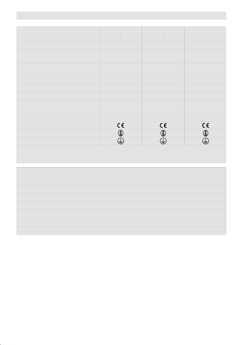
Technische Daten
Spannung V~ 3 × 230 3 × 400 3 × 480
Leistung kW 6 10 6 11 6 11
Frequenz Hz 50 / 60 50 / 60 50 / 60
Max. Luftaustritts-
temperatur
Max. Lufteintritts-
temperatur
°C
°C
Luftmenge (20 °C) l/min. 850 / 1500 950 / 1700 950 / 1700
Statischer Druck max. Pa 3100 / 4000 3100 / 4000 3100 / 4000
Emissionspegel L
pA
(dB)
Gewicht kg
ohne Netzanschlussleitung
Masse Seite 3 (Size) Seite 3 (Size) Seite 3 (Size)
Konformitätszeichen
Sicherheitszeichen
Schutzklasse I
Technische Änderungen vorbehalten
Anschlussspannung nicht umschaltbar
• Heizleistung mittels Potentiometer stufenlos einstellbar
• Integrierte Leistungselektronik
• Schutz vor Heizelement- und Geräteüberhitzung
• Bürstenloser Gebläsemotor mit FU ansteuerbar
• Alarmausgang
• Integrierter Temperaturregler
• Integrierte Temperatursonde
• Display zur Anzeige der Soll- und Ist-Werte (°C oder °F)
650 650 650
65 65 65
65 65 65
9.3 9.3 9.3
9

Technische Daten Schnittstellen
Max. Spannungen AC 250 V, DC 30 V
Max. Ströme AC 3 A, DC 3 A
Relaisausgang
Signaleingänge
mit Verpolungsschutz und
Nullpunktkorrektur
Speisung
mit Verpolungsschutz
ohne Trennung von den
Signaleingängen
Max. Kontaktwiderstand 100 m Ohm bei DC 6 V / 1 A
Kontaktart SPST - NO
Isolation IEC/EN 60065 AC 2000 V (50 - 60 Hz) 1 min
Isolation IEC/EN 60747-5-2 AC 1414 V Peak
Spannungseingang Uc bezogen
auf GND iso
Max. Eingangsspannung DC 12 V
Nenn-Eingangswiderstand 280 kOhm
Stromeingang Ic (2 - Leiter Technik)
Max. Eingangsstrom DC 22 mA
Nenn-Eingangswiderstand 160 Ohm
Betriebsspannung Us bezogen auf
GND iso
Max. Betriebsspannung DC 25 V
Stromaufnahme 12 mA bei DC 24 V
DC 0 - 10 V
(Rippel < 0.05 V bei
5 °C Auflösung)
(Rippel < 0.1 V bei
1 % Auflösung)
DC 4…20 mA
(Rippel < 0.1 mA bei
5 °C Auflösung)
(Rippel < 0.15 mA bei
1 % Auflösung)
DC 15…24 V
ACHTUNG: Bei Verwendung als Einbaugerät muss im Netzanschluss eine geeignete Vorrichtung
zur allpoligen Trennung vom Netz mit einem Kontaktabstand von 3 mm vorhanden sein.
Alarmkontakt: SPST– NO 250 VAC / 30 VDC, 3 A cos ϕ = 1
Technische Daten interner Kodierschalter
Stellgrad OFF…100 %;
1% Schritte
Sollwertvorgabe 50 °C…650 °C,
5 °C Schritte
Sollwert OFF…100 % oder
50 °C …650 °C
Sollwert OFF…100 % oder
50 °C …650 °C
Open Loop oder Closed Loop
Sollwertvorgabe
Potentiometer oder
Schnittstelle
10
Stellfunktion Leistung
Reglerfunktion Temperatur
Internes Potentiometer
Schnittstelle
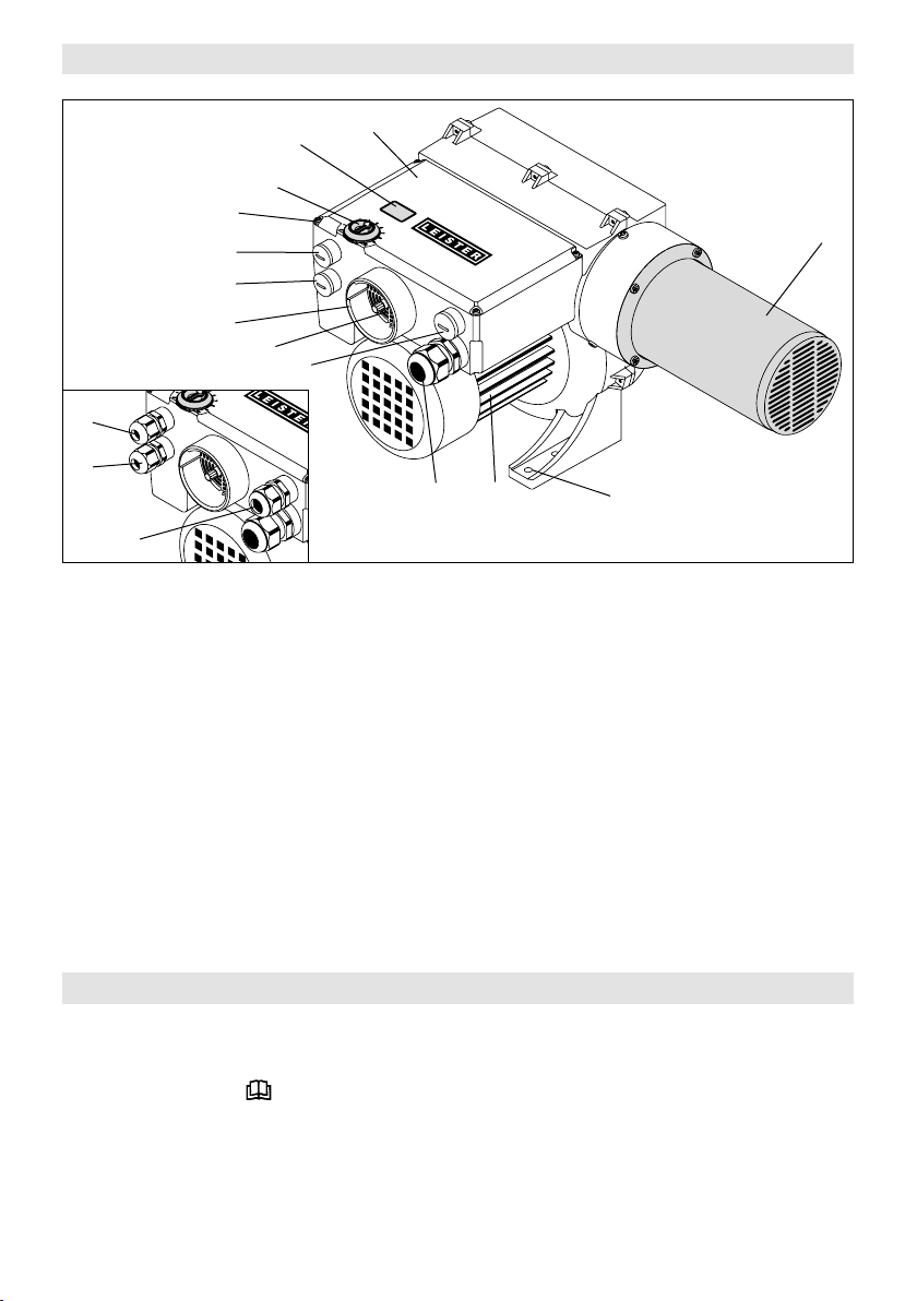
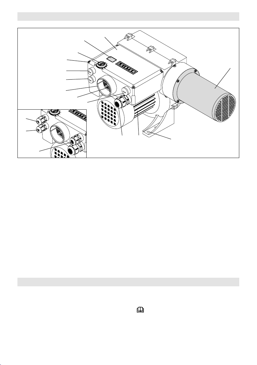
Gerätebeschreibung
11
10
13
4
3
8
9
7
6
5
1 Kabelverschraubung für Netzanschluss
(ab Werk montiert)
2 Verschlussschraube für Frequenzumformer
(ab Werk montiert)
3 Verschlussschraube für Alarm-Relais
(ab Werk montiert)
4 Verschlussschraube für Schnittstelle
(ab Werk montiert)
5 Kabelverschraubung für Frequenzumformer
(beigepackt im Anschlussgehäuse)
6 Kabelverschraubung für Alarm-Relais
(beigepackt im Anschlussgehäuse)
12
2
14
1
16
7 Kabelverschraubung für Schnittstelle
8 Flansch ø 60 mm
9 Luftschieber
10 Potentiometer für Temperatureinstellung
11 Display
12 Abdeckung und Anschlussgehäuse
13 Schrauben für Anschlussgehäuse
14 Heizelementrohr
15 Montagefuss
16 Gebläsemotor
15
(beigepackt im Anschlussgehäuse)
Vorbereitung
• VULCAN SYSTEM aus der Verpackung entnehmen.
• Durch Lösen der Schrauben (13) die Abdeckung Anschlussgehäuse (12) entfernen.
• Warnzettel entnehmen, aufmerksam lesen und zur weiteren Verfügung aufbewahren.
•
Verschlussschrauben (ab Werk montiert) für Frequenzumformer (2), Alarm-Relais (3) und für Schnittstelle (4)
entfernen.
• Die beigepackten Kabelverschraubungen für Frequenzumformer (5), Alarm-Relais (6) und für Schnitt-
stelle (7) bei Bedarf montieren.
• Wird keine Schnittstelle oder FU / FC (Frequenzumrichter) verwendet, müssen die Kabelverschraubungen (5 / 7)
entfernt und die Verschlussschrauben (2 / 4) montiert werden.
11
Einbau
• Der Einbau muss gewährleisten, dass
– nur kalte Luft zugeführt wird.
– kein (Wärme-) Rückstau entsteht.
– das Gerät nicht vom Heissluftstrahl eines anderen Gerätes angeströmt wird.
• VULCAN SYTEM vor mechanischen Vibrationen und Erschütterungen schützen.
• VULCAN SYTEM vier Schrauben Ø M6 am Montagefuss (15) befestigen.
• Einbaumasse siehe Seite 3 (Size)
Luftversorgung
• Als Luftversorgung dient das integrierte Gebläse (Drehrichtung und Kompressionserwärmung beachten).
• Um Gerät und Heizelement zu schützen, darf die vorgeschriebene minimale Luftmenge keinesfalls unterschritten und die maximale Temperatur (heissester Punkt 3 mm vor dem Heizelementrohr gemessen) keinesfalls
überschritten werden (siehe technische Daten). Falls die minimale Luftmenge unterschritten wird, muss sofort
die Heizleistung unterbrochen werden.
• Luftmenge bei Bedarf mit Luftschieber (9) reduzieren.
• Luftdurchflussrichtung beachten.
• Bei staubhaltiger Luft Leister Edelstahlfilter verwenden. Aufschiebbar auf Flansch (8). Bei besonders kritischen
Stäuben (z.B. Metall-, elektrisch leitende oder feuchte Stäube) müssen spezielle Filter verwendet werden, um
Kurzschlüsse im Gerät zu vermeiden.
Achtung: Gerät immer mit Luftversorgung betreiben !
Anschluss
• Der VULCAN SYSTEM muss durch Fachpersonen angeschlossen werden.
• Im Netzanschluss muss eine geeignete Vorrichtung zur allpoligen Trennung vom Netz vorhanden sein !
• Es muss sichergestellt sein, dass die Anschlussleitungen das Heizelementrohr nicht berühren und dem Heissluftstrahl nicht ausgesetzt sind.
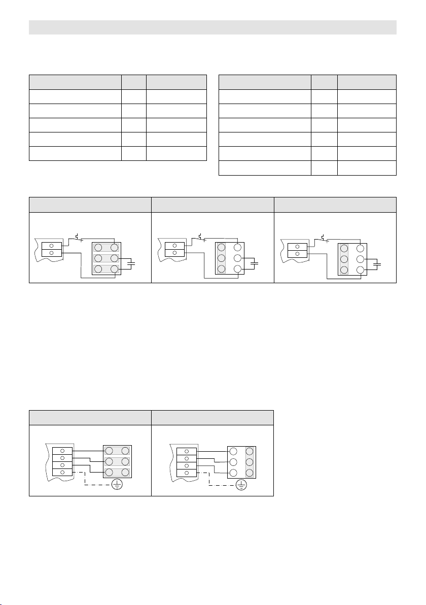
• Das Gerät muss gemäss dem Anschlussschema und der Klemmanordnung auf Seite 4 (Wiring Diagram)
und Seite 5 (Interface) der Bedienungsanleitung angeschlossen werden:
– Verdrahtung im Anschlussgehäuse (12) vornehmen.
• ACHTUNG: Die Einstellungen des Kodierschalters prüfen (siehe Kapitel Konfiguration interner Kodierschalter).
• Abdeckung Anschlussgehäuse (12) mit den Schrauben (13) montieren.
• VULCAN SYSTEM an das elektrische Netz anschliessen.
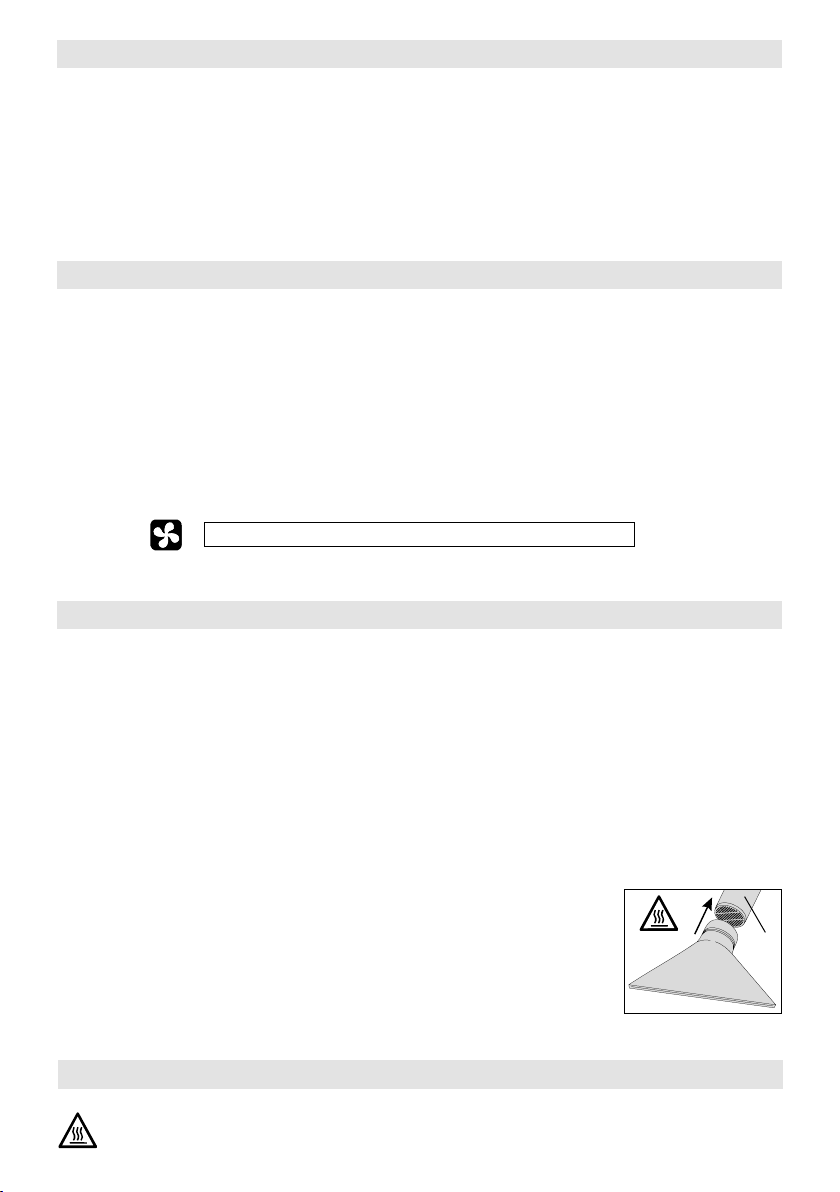
• Nach Bedarf entsprechende Düse oder Reflektor auf Heizelementrohr (14) schieben.
• Es muss darauf geachtet werden, dass die Heissluft frei ausströmen kann, da
ansonsten durch Wärmerückstau das Gerät Schaden erleiden kann (Brandgefahr !).
• Achtung: Minimale Luftmenge gemäss technischen Daten einhalten.
• Netz einschalten.
• Gerät nach dem Heizbetrieb nachkühlen lassen.
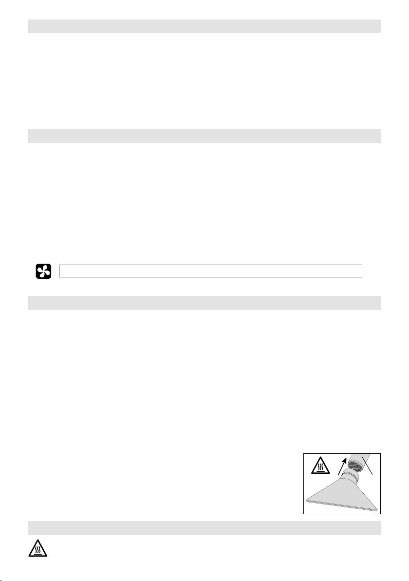
Düsen- / Reflektor-Wechsel
Verbrennungsgefahr! Heizelementrohr und Düse nicht in heissem Zustand berühren.
12
Beim Wechseln der Düse oder des Reflektors zuvor Gerät abkühlen lassen.
14
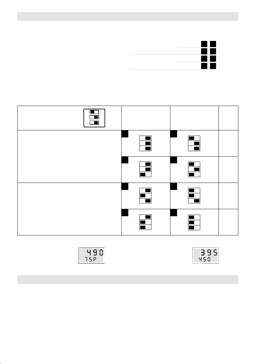
Konfiguration interner Kodierschalter
°C
• Wahlweise unterschiedliche Betriebsmodi, welche mit integriertem Kodierschalter eingestellt werden.
Kodierschalter nur im ausgeschalteten Zustand betätigen !
– Stufenlos einstellbare Heizleistung mittels rotem Potentiometer (10) auf dem Gerät
– Stufenlos einstellbare Heizleistung mittels Schnittstelle
– Stufenlos einstellbare Temperatur mittels rotem Potentiometer (10) auf dem Gerät
– Stufenlos einstellbare Temperatur mittels Schnittstelle
– Integrierte Temperaturanzeige (11) in °C oder °F
• Das Gerät ist mit integriertem Heizelement- und Geräteschutz
ausgestattet
(siehe Kapitel Funktion Heizelement- / Geräteschutz).
• Einstellungen zur Selektion der verschiedenen Betriebsmodi:
1 2
3 4
5 6
7 8
Mode
CLL = Closed Loop
OPL = Open Loop
CLL
Interf
°F
ON
3
2
1
Potentiometer - Modus (Pot)
Schnittstellen - Modus (Interf)
Modus gesteuert (OPL)
Das Display zeigt Leistungssollwert in % und Istwert der
Temperatur an
°C
Funktion Heizelement- / Geräteschutz
OPL
Pot
°C
1
2
3
4
Istwert
Sollwert %
Modus gesteuert
(Leistungsvorgabe)
OPL
1 2 3
ON
1 2 3
ON
1 2 3
ON
1 2 3
ON
Modus geregelt (CLL)
Das Display zeigt
Ist- und Sollwert
der Temperatur an
Modus geregelt
(Temperaturvorgabe)
CLL
5
1 2 3
ON
6
1 2 3
ON
7
1 2 3
ON
8
1 2 3
ON
Anzeige
°C
°F
°C
°F
Istwert
Sollwert
• Überhitzen Heizelement oder Gerät (zu warme Zuluft oder Wärmerückstau) wird die Leistungszufuhr zum
Heizelement unterbrochen und der Arbeitskontakt des Alarmrelais geönet. Nach Ansprechen des Heizelementschutzes oder Geräteschutzes ist aus Sicherheitsgründen ein Rückstellen (Reset) des VULCAN SYSTEM nötig !
• WICHTIG: Massnahmen beim Ansprechen des Heizelementschutzes oder Geräteschutzes
– Gerät 10 Sekunden vom Netz trennen
– Luftzufuhr überprüfen
– Luftmenge überprüfen
– Luftdurchlass überprüfen
– Gerät wieder mit Netz verbinden
13

FU / FC Frequenzumformer - Betrieb
U1
V1
W1 V2
U2
W2
12μF
9
8
T
C
U1
V1
W1 V2
U2
W2
12μF
9
8
T
U1
V1
W1 V2
U2
W2
4μF
9
8
T
C
C
U1
V1
W1 V2
U2
W2
12μF
9
8
T
U1
V1
W1 V2
U2
W2
4μF
9
8
T
U1
V1
W1 V2
U2
W2
2μF
9
8
T
C
C
C
U1
V1
W1 V2
U2
W2
12μF
9
8
T
U1
V1
W1 V2
U2
W2
4μF
9
8
T
U1
V1
W1 V2
U2
W2
2μF
9
8
T
U1
V1
W1 V2
U2
W2
U
V
W
PE
C
C
C
Konfiguration Frequenzumformer FC 550
• Anschluss-Schema Seite 6 (Wiring Diagram)
Parameter No. Einstellwert
Min. Frequenz 01 20 Hz
Max. Frequenz 02 60 Hz
Beschleunigungszeit 03 5 s
Verzögerungszeit 04 10 s
Umrichterkonfiguration 05 Pr
Parameter No. Einstellwert
Motor-Nennstrom 06 0.65 A
Motor-Nenndrehzahl 07 2790 rpm
Motor-Nennspannung 08 230
Motor-Leistungsfaktor 09 0.70
Festsollwert 1 18 20 – 60 Hz
Max. Taktfrequenz 37 18 kHz
Motor-Anschluss Auslieferzustand
3 × 230 V 3 × 400 V 3 × 480 V
Elektrische
Schaltung
9
8
T
U1
V1
W1 V2
W2
U2
12μF
C
Elektrische
Schaltung
9
8
Elektrische
4μF
C
Schaltung
9
8
T
U1
W2
V1
W1 V2
C
U2
2μF
T
U1
W2
V1
U2
W1 V2
FU / FC Frequenzumformer Anschluss-Schema
• Den VULCAN SYSTEM gibt es in drei Spannungsversionen und das Gebläse kann mittels FU / FC (Frequenz-
umformer) in 3 × 230 V und 3 × 400 V angesteuert werden.
• Um den Frequenzumformer mit der internen Schaltung zu verbinden, müssen nachfolgende Schritte eingehalten
– Weisse und braune Litze von der Klemme Nr. 8 und 9 der elektrischen Schaltung entfernen.
– Kondensator (C) entfernen.
– Anschlüsse der weissen Litzen vom Temperaturschalter (T) mit Isolierband isolieren und überstehende Enden
werden:
in den Motorenkasten zurückschieben.
FU / FC (FC 550) 3 × 230V FU / FC 3 × 400 – 480 V
FU /FC Extern FU /FC Extern
U
V
W
PE
14
U1
V1
W1 V2
W2
U2
U1
V1
W1 V2
W2
U2
U
V
W
PE

Error
Display Bezeichnung Fehlerbehebung
Err 01 Gerätetemperatur zu hoch
Err 02 Heizelement temperatur zu hoch Luftmenge prüfen
Err 03 Temperatursonde Anschluss der Temperatursonde kontrollieren
Err 04
Err 05
Err 06
Err 07
Leister Service-Stelle kontaktierten
Umgebungstemperatur prüfen
Zulufttemperatur prüfen
Schulung
Leister Technologies AG sowie deren autorisierte Service-Stellen bieten kostenlose Kurse im Bereich der
Anwendungen an.
3D Zeichnungen
3D-Zeichnungen sind bei ihrer Service-Stelle oder auf www.leister.com erhältlich.
Zubehör
• Es darf nur Leister-Zubehör verwendet werden.
• Leister bietet ein grosses Sortiment an Zubehör, z.B.
– Frequenzumformer FC 550, Art. Nr. 117.359
– Temperaturregler
– Düsen
– Reflektoren
• Zubehör unter www.leister.com
Service und Reparatur
• Reparaturen sind ausschliesslich von autorisierten Leister Service-Stellen ausführen zu lassen. Diese gewähr-
leisten innert nützlicher Frist einen fachgerechten und zuverlässigen Reparatur-Service mit Original-Ersatzteilen
gemäss Schaltplänen und Ersatzteillisten.
Gewährleistung
• Für dieses Gerät gelten die vom direkten Vertriebspartner/Verkäufer gewährten Garantie- oder Gewährleistungsrechte ab Kaufdatum. Bei einem Garantie- oder Gewährleistungsanspruch (Nachweis durch Rechnung
oder Lieferschein) werden Herstellungs- oder Verarbeitungsfehler vom Vertriebspartner durch Ersatzlieferung oder Reparatur beseitigt. Heizelemente sind von der Gewährleistung oder Garantie ausgeschlossen.
• Weitere Garantie- oder Gewährleistungsansprüche werden im Rahmen des zwingenden Rechts ausgeschlossen.
• Schäden, die auf natürliche Abnutzung, Überlastung oder unsachgemässe Behandlung zurückzuführen sind,
werden von der Gewährleistung ausgeschlossen.
• Keine Garantie- oder Gewährleistungsansprüche bestehen bei Geräten, die vom Käufer umgebaut oder
verändert wurden.
15
GB
Operating Instructions
Congratulations on purchasing a
You have chosen a top-class hot air blower by Leister, made from high-quality materials. Every VULCAN
SYSTEM undergoes stringent quality checks before leaving the factory in Switzerland.
VULCAN SYSTEM !
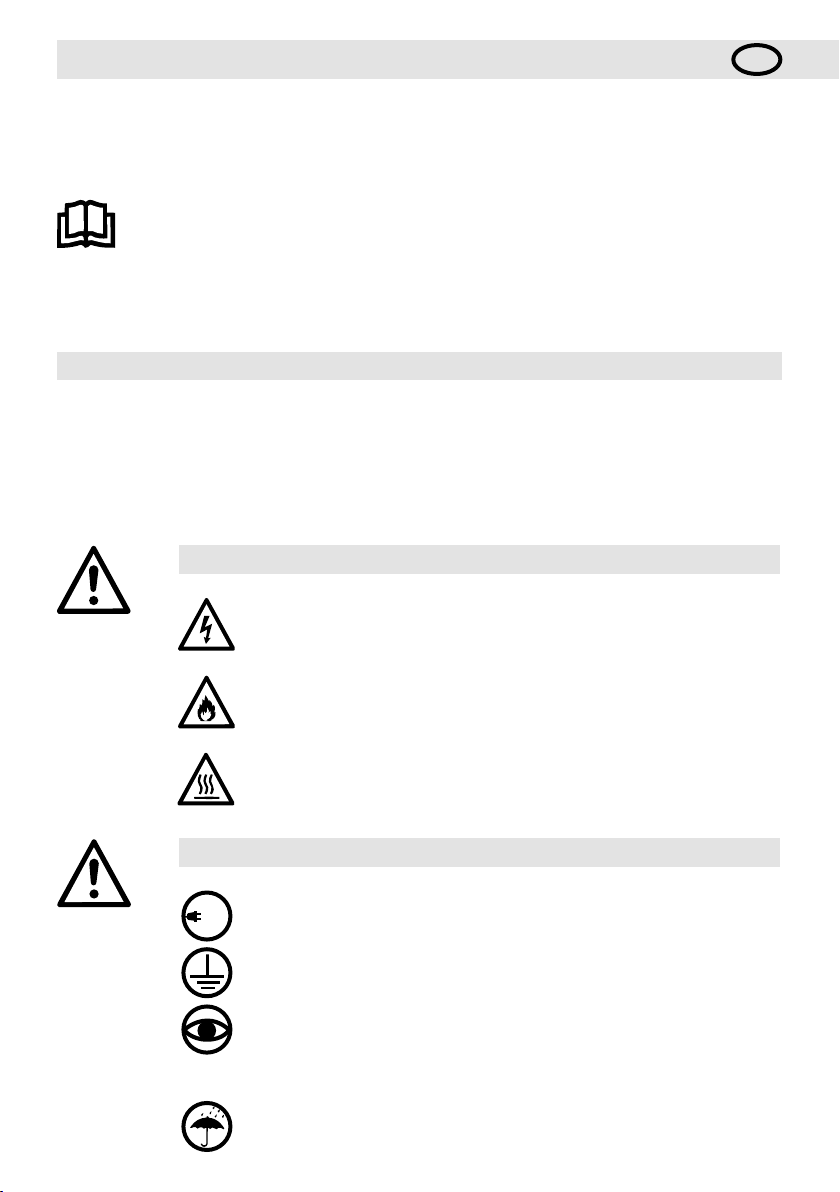
Please read operating instructions carefully before use
and keep for future reference.
Hot air blower
VULCAN SYSTEM
Application
The hot air blower VULCAN SYSTEM is suitable for building into machines, installations or appliances and is
designed for continuous operation.
Its most important applications include; drying and heating, thawing, accelerating and removal, sterilising,
smoothing, polishing, activation and dissolving, separating and fusing, shrinking, removal.
Warning
Danger of death when opening the device, as live parts and connections are
exposed. The device must be fully disconnected from the mains before opening it.
Incorrect use of the hot air blower can present a fire and explosion hazard
especially near combustable materials and explosive gases.
Danger – can cause burns! Do not touch the heating element tube and nozzle
while they are hot. Allow the device to cool. Do not direct hot-air stream towards
people or animals.
Caution
230
400
16
The nominal voltage indicated on the device must correspond to the mains
voltage. EN 61000-3-11; Z
electricity supply utility.
Devices of protection class I must be earthed with a protective earth conductor.
The device must not be left unattended when in use.
Heat can reach combustible materials which are out of sight. The device may only
be used by trained personnel or under their supervision. Children may not use
the device under any circumstances.
Keep away from wet and damp areas.
= 0.033 Ω + j 0.021 Ω.
max
If necessary, consult your

Disposal
Electrical equipment, accessories and packaging should be recycled in an environmentally friendly
way. For EU countries only: Do not dispose of electrical equipment with household refuse!
17
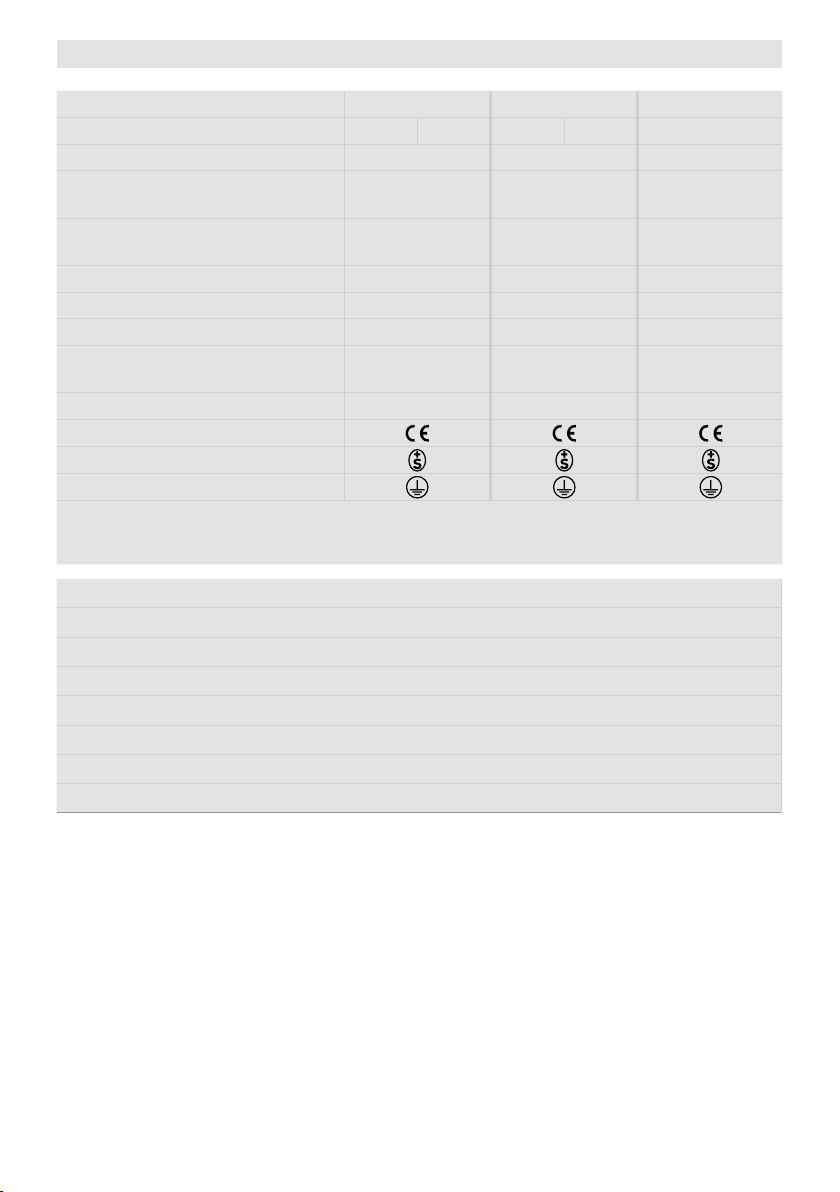
Technical Data
Voltage V~ 3 × 230 3 × 400 3 × 480
Power consumption kW 6 10 6 11 6 11
Frequency Hz 50 / 60 50 / 60 50 / 60
Max. air outlet
temperature
Max. air inlet
temperature
°C
°C
Air volume (20 °C) l/min. 850 / 1500 950 / 1700 950 / 1700
Max. static pressure Pa 3100 / 4000 3100 / 4000 3100 / 4000
Emission level L
pA
(dB)
Weight kg
without power supply cord
Dimensions Page 3 (Size) Page 3 (Size) Page 3 (Size)
Mark of conformity
Approval mark
Protection class I
Technical data and specifications are subject to change without prior notice
Mains voltage cannot be switched over
• Heat output steplessly adjustable with potentiometer
• Integrated power electronics
• Protection against heating element or device overheating
• Brushless blower motor with FC control
• Alarm output
• Integrated temperature control
• Integrated temperature probe
• Display for showing the setpoint and actual values (°C or °F)
650 650 650
65 65 65
65 65 65
9.3 9.3 9.3
18

Technical data for interface
Relay output
Signal inputs
with reverse polarity protection
and zero point correction
Supply
with reverse polarity protection
without separation of the
signal inputs
Max. voltages AC 250 V, DC 30 V
Max. currents AC 3 A, DC 3 A
Max. contact resistance 100 m Ohm at DC 6 V / 1 A
Relay contact SPST - NO
Insulation IEC/EN 60065 AC 2000 V (50 - 60 Hz) 1 min
Insulation IEC/EN 60747-5-2 AC 1414 V Peak
DC 0 - 10 V
Voltage input Uc in relation to
GND iso
Max. input voltage DC 12 V
Nominal input resistance 280 kOhm
Current input Ic (2 - conductor
technology)
Max. input current DC 22 mA
Nominal input resistance 160 Ohm
Operating voltage Us in relation to
GND iso
Max. operating voltage DC 25 V
Power consumption 12 mA at DC 24 V
(Rippel < 0.05 V at
5 °C resolution)
(Rippel < 0.1 V at
1 % resolution)
DC 4…20 mA
(Rippel < 0.1 mA at
5 °C resolution)
(Rippel < 0.15 mA at
1 % resolution)
DC 15…24 V
CAUTION : When fixing the tool into an installation, the mains connection must have a suitable device for disconnect all poles from the mains with a 3 mm distance between contacts.
Alarm contact: SPST– NO 250 VAC / 30 VDC, 3 A cos ϕ = 1
Technical data internal dip switch
Setting level OFF…100 %;
1% steps
Setpoint value specification
50 °C…650 °C, 5 °C steps
Setpoint value OFF…100 % or
50 °C …650 °C
Setpoint value OFF…100 % or
50 °C …650 °C
Open Loop or Closed Loop
Setpoint setting
Potentiometer or
interface
Power setting function
Temperature control function
Internal potentiometer
Interface
19

Device description
11
10
13
4
3
8
9
7
6
5
1 Cable gland for mains connection
(mounted ex works)
2 Locking screw for frequency converter
(mounted ex works)
3 Locking screw for alarm relay
(mounted ex works)
4 Locking screw for interface
(mounted ex works)
5 Cable gland for frequency converter
(enclosed in the connection housing)
6 Cable gland for alarm relay
(enclosed in the connection housing)
12
2
14
1
16
7 Cable gland for interface
8 Flange ø 60 mm
9 Air slide
10 Potentiometer for temperature setting
11 Display
12 Connection and housing cover
13 Screws for connection housing
14 Heating element tube
15 Mounting base
16 Blower motor
15
(enclosed in the connection housing)
Preparation
• Remove VULCAN SYSTEM from the packaging.
• Remove the connection housing cover (12) by loosening the screws (13).
• Remove warning slip, read carefully and keep at hand for consultation.
•
Remove locking screws (mounted ex works) for the frequency converter (2), alarm relay (3) and interface (4).
• Mount the enclosed cable glands for the frequency converter (5), alarm relay (6) and interface (7), if
required.
• If no interface or FU / FC (frequency converter) is used, the cable glands (5 / 7) must be removed and the locking
screws (2 / 4) mounted.
20
Installation
• The installation must ensure that
– only cold air is supplied.
– no excess (heat) residue builds up.
– the device is not subject to jets of hot air from another device.
• Protect the VULCYAN SYSTEM from mechanical vibrations and shocks.
• Fasten the tool on the mounting base (15) using four screws Ø M6.
• For installation dimensions, see page 3 (Size).
Air supply
• The integrated blower serves as an air supply (note direction of rotation and compression heating).
• In order to protect the device and heating element, the specified minimum air volume must never be fallen below
and the maximum temperature (hottest point measured 3 mm in front of the heating element tube) must never
be exceeded (see technical specifications). If the minimum air volume is fallen below, the heat output must
be interrupted immediately.
• Reduce air flow as required by use of the air slide (9).
• Observe direction of air flow.
• Use Leister stainless steel filters if the air is dusty. Slides onto flange (8). In the case of particularly critical dusts
(e.g. metal, electrically conductive or damp dusts), special filters must be used to avoid short-circuits in the tool.
Attention: always operate device with air supply !
Connection
• The VULCAN SYSTEM must be connected by qualified personnel.
• A suitable device for full disconnection from the mains must be provided in the mains connection!
• It must be ensured that the connection lines do not come into contact with the heating element tube and are not
exposed to the hot air jet.
• The device must be connected in accordance with the connection diagram and the terminal arrangement on page 4 (Wiring Diagram) and page 5 (Interface) of the operating instructions:
– Carry out wiring in the connection housing (12).
• ATTENTION: check dip switch settings (see chapter Configuration internal dip switch).
• Mount connection housing cover (12) with the screws (13).
• Connect VULCAN SYSTEM to the electrical mains.
• Slide corresponding nozzle or reflector onto heating element tube (14), if required.
• It must be ensured that the hot air can flow out freely, as otherwise the device can
be damaged by the excess heat building up (risk of fire !).
• Attention: comply with minimum air volume as per technical data.
• Switch on mains.
• Allow device to cool down after heating mode.
14
Nozzles / Reflector - change
Danger – can cause burns! Do not touch the heating element tube and nozzle while they are hot.
Allow the tool to cool down before replacing the nozzle or reflector.
21

°C
Configuration internal dip switch
°C
• Optionally dierent operating modes which are set with an integrated dip switch
Only operate the dip switch when switched o !
– Steplessly adjustable heat output via red potentiometer (10) on the device
– Steplessly adjustable heat output via interface
– Steplessly adjustable temperature via red potentiometer (10) on the device
– Steplessly adjustable temperature via interface
– Integrated temperature display in °C or °F
• The device is fitted with an integral heating element and device protection
(see chapter Function of heating element - device protection).
• Settings for selecting the various operating modes:
1 2
3 4
5 6
7 8
Mode
CLL = Closed Loop
OPL = Open Loop
CLL
Interf
°F
ON
3
2
1
OPL
Pot
°C
Open Loop
(power set point)
1
Potentiometer mode (Pot)
2
3
Interface mode (Interf)
4
Open Loop mode (OPL)
Display shows power
setpoint in % and actual
temperature
Actual temp
Setpoint %
Function of heating element – device protection
Closed Loop
(temperature set point)
OPL
5
1 2 3
ON
6
1 2 3
ON
7
1 2 3
ON
8
1 2 3
ON
Closed Loop mode (CLL)
Display shows setpoint
temperature and actual
temperature
ON
ON
ON
ON
CLL
1 2 3
1 2 3
1 2 3
1 2 3
Actual temp
Setpoint
Display
°C
°F
°C
°F
• If the heating element or device overheats (too hot inlet air or excess heat residue), the power supply to the
heating element will be interrupted and the working contact of the alarm relay opened. After the heating element
or device protection is activated, it will be necessary to reset the VULCAN SYSTEM for reasons of safety !
• IMPORTANT: measures to take when the heating element or device protection is activated
– Disconnect device from the mains for 10 seconds
– Check air supply
– Check air volume
– Check air flow
– Reconnect device to the mains
22
FU / FC Frequency converter operation
U1
V1
W1 V2
U2
W2
12μF
9
8
T
C
U1
V1
W1 V2
U2
W2
12μF
9
8
T
U1
V1
W1 V2
U2
W2
4μF
9
8
T
C
C
U1
V1
W1 V2
U2
W2
12μF
9
8
T
U1
V1
W1 V2
U2
W2
4μF
9
8
T
U1
V1
W1 V2
U2
W2
2μF
9
8
T
C
C
C
U1
V1
W1 V2
U2
W2
12μF
9
8
T
U1
V1
W1 V2
U2
W2
4μF
9
8
T
U1
V1
W1 V2
U2
W2
2μF
9
8
T
U1
V1
W1 V2
U2
W2
U
V
W
PE
C
C
C
Configuration frequency converter FC 550
• Wiring diagram page 6
Parameters No. Default value
Min. frequency 01 20 Hz
Max. frequency 02 60 Hz
Acceleration time 03 5 s
Deceleration time 04 10 s
FC configuration 05 Pr
Parameters No. Default value
Nominal current 06 0.65 A
Nominal speed 07 2790 rpm
Nominal voltage 08 230
Motor power factor 09 0.70
Preset speed 1 18 20 – 60 Hz
Clock frequency 37 18 kHz
Motor connection status as supplied
3 × 230 V 3 × 400 V 3 × 480 V
Electrical
circuit
9
8
T
U1
V1
W1 V2
W2
U2
12μF
C
Electrical
circuit
9
8
Electrical
4μF
circuit
C
T
9
8
U1
V1
W1 V2
W2
C
U2
2μF
T
U1
W2
V1
U2
W1 V2
FU / FC frequency converter wiring diagram
• The VULCAN SYSTEM is available in three voltage versions and the blower can be activated via the FU/FC
(frequency converter) in 3 × 230V and 3 × 400V.
• The following steps have to be followed to connect the frequency converter to the internal circuit:
– Remove white and brown wires from terminals 8 and 9 of the electric circuit.
– Remove capacitor (C).
– Insulate connections of the white wires from the temperature switch (T) with insulating tape and push
protruding ends back into the motor box.
FU / FC (FC 550) 3 × 230V FU / FC 3 × 400 – 480 V
FU /FC external FU /FC external
U
V
W
PE
U1
V1
W1 V2
W2
U2
U
V
W
PE
U1
V1
W1 V2
W2
U2
23

Error
Display Description Fault correction
Err 01 Device temperature too high
Err 02 Heating element temperature too high Check air supply volume
Err 03 Temperature probe Check probe connection
Err 04
Err 05
Err 06
Err 07
Contact your Leister Service Centres
Check environment temperature
Check air intake temperature
Training
Leister Technologies AG and its authorised service points provide free courses in the area of applications.
3D drawings
3D drawings are available from your Service Centre or at www.leister.com
Accessories
• Only Leister accessories may be used.
• Leister offers a wide range of accessories, e.g.
– Frequency converter FC 550, Art. Nr. 117.359
– Temperature controls
– Nozzles
– Reflectors
• Accessories at www.leister.com
Service and Repairs
• Repairs should only be carried out by authorised Leister Service Centres. They guarantee a correct and reliable
repair service within reasonable period, using original spare parts in accordance with the circuit diagrams and
spare parts lists.
Warranty
• For this tool, the guarantee or warranty rights granted by the relevant distributor/seller shall apply. In case of
guarantee or warranty claims any manufacturing or workmanship defects will either be repaired or replaced by the
distributor at its discretion. Warranty or guarantee rights have to be verified by an invoice or a delivery document.
Heating elements shall be excluded from warranty or guarantee.
• Additional guarantee or warranty claims shall be excluded, subject to mandatory provisions of law.
• Warranty or guarantee shall not apply to defects caused by normal wear and tear, overload or improper handling.
• Warranty or guarantee claims will be rejected for tools that have been altered or changed by the purchaser.
24
Istruzioni per l‘uso
Congratulazioni per l’acquisto di VULCAN SYSTEM !
È stato scelta un‘eccellente soatrice d‘aria calda di Leister realizzata con materiali di alta qualità. Prima di uscire
dallo stabilimento in Svizzera, tutti i modelli di VULCAN SYSTEM sono sottoposti ad un rigoroso controllo di qualità.
I
Prima dell‘attivazione leggere con attenzione le istruzioni
per l‘uso e conservarle per ulteriori consultazioni.
Soffiatrice di aria calda
VULCAN SYSTEM
Aplication
La soatrice di aria calda VULCAN SYSTEM è adatta per l‘installazione in macchine, impianti o apparecchiature ed
è progettata per il funzionamento continuo.
Le sue più importanti applicazioni sono ad esempio essiccazione e riscaldamento, scongelamento,
accelerazione e miscelazione, sterilizzazione, levigatura, lucidatura, attivazione e allentamento,
separazione e fusione, termoretrazione, rimozione.
Avvertenze
Aprendo l‘apparecchio è presente il pericolo di morte perché vengono esposti
componenti e collegamenti sotto tensione. Prima di aprire l‘apparecchio è necessario scollegarne tutti i poli dalla rete elettrica.
Cautela
230
400
È presente il pericolo di incendio e di esplosione in caso di utilizzo non conforme
degli apparecchi ad aria calda, in particolare nelle vicinanze di materiali infiammabili e gas esplosivi.
Pericolo di ustione! Non toccare il tubo della resistenza e l‘ugello quando
sono ancora ad alte temperature. Lasciar raffreddare l‘apparecchio.
Non orientare il getto di aria calda verso persone o animali.
La tensione nominale specificata sull‘apparecchio deve coincidere con la tensione di rete. EN 61000-3-11; Z
consultare l‘azienda addetta all‘erogazione della corrente elettrica.
È obbligatorio collegare a massa l‘apparecchio della classe di protezione I con il
conduttore di terra.
È necessario mantenere l‘apparecchio sotto controllo durante il funzionamento. Il
calore può raggiungere materiali infiammabili che si trovano fuori dal campo visivo.
L‘impiego dell‘apparecchio è consentito esclusivamente a personale specializzato
o sotto il monitoraggio di quest‘ultimo. È tassativamente vietato l‘impiego da parte
dei bambini.
Proteggere l‘apparecchio da umidità e da ambienti bagnati.
= 0.033 Ω + j 0.021 Ω. In caso di necessità
max
25

Smaltimento
Gli apparecchiature elettriche, gli accessori e gli imballaggi devono essere riciclati nel rispetto dell’ambiente. Solo per i Paesi UE: Non smaltire gli apparecchiature elettriche insieme ai rifiuti domestici!
26
Specifiche tecniche
Tensione V~ 3 × 230 3 × 400 3 × 480
Potenza kW 6 10 6 11 6 11
Frequenza Hz 50 / 60 50 / 60 50 / 60
Temperatura max.
dell›aria in uscita
Temperatura max.
dell›aria in ingresso
Portata d›aria (20 °C) l/min. 850 / 1500 950 / 1700 950 / 1700
Pressione statica max. Pa 3100 / 4000 3100 / 4000 3100 / 4000
Livello di emissioni acustiche
Peso kg
senza linea di allacciamento alla rete
Dimensioni Pagina 3 (Size) Pagina 3 (Size) Pagina 3 (Size)
Marchio di conformità
Marchio di sicurezza
Classe di protezione I
Con riserva di modifiche tecniche
Tensione di allacciamento non commutabile
• Possibilità di regolazione in modo continuo della potenza di riscaldamento con il potenziometro
• Impianto elettronico integrato della potenza
• Protezione dal surriscaldamento della resistenza e dell›apparecchio
• Possibilità di controllo del motore della ventola senza spazzole con inverter
• Uscita d›allarme
• Termostato integrato
• Sonda termica integrata
• Display di visualizzazione dei valori nominali e reali (°C o °F)
°C
°C
LpA (dB)
650 650 650
65 65 65
65 65 65
9.3 9.3 9.3
27

Specifiche tecniche dell‘interfaccia
Tensioni max. AC 250 V, DC 30 V
Correnti max. AC 3 A, DC 3 A
Uscita relè
Ingressi dei segnali
con protezione sull›inversione
di polarità e compensazione del
punto neutro
Alimentazione
con protezione sull›inversione
di polarità senza interruzione
dagli
ingressi dei segnali
Resistenza di contatto max. 100 m Ohm a DC 6 V / 1 A
Tipo di contatto SPST - NO
Isolamento IEC/EN 60065 AC 2000 V (50 - 60 Hz) 1 min
Isolamento IEC/EN 60747-5-2 AC 1414 V Peak
Ingresso della tensione Uc in
riferimento a GND iso
Tensione d›ingresso max.
Resistenza d›ingresso nominale 280 kOhm
Ingresso di corrente
(tecnica a 2 conduttori)
Tensione d›ingresso max. DC 22 mA
Resistenza d›ingresso nominale 160 Ohm
Tensione d‘esercizio Us in
riferimento a GND iso
Tensione d‘esercizio max. DC 25 V
Assorbimento di corrente 12 mA a DC 24 V
DC 0 - 10 V
(ondulazione < 0.05 V a
5 °C di risoluzione)
(ondulazione < 0.1 V a
1 % di risoluzione)
DC 12 V
DC 4…20 mA
(ondulazione < 0.1 mA a
5 °C di risoluzione)
(ondulazione < 0.15 mA a
1 % di risoluzione)
DC 15…24 V
ATTENZIONE ! In caso di impiego come apparecchiatura destinata all‘installazione deve essere presente all‘interno del collegamento alla rete un dispositivo adeguato per garantire la
disconnessione di tutti i poli dalla rete con una distanza dei contatti di 3 mm.
Contatto di allarme: SPST– NO 250 VAC / 30 VDC, 3 A cos ϕ = 1
Specifiche tecniche Dip Switch interno
Grado d›impostazione
OFF…100 %; scatti da 1%
Preimpostazione valore nominale
50 °C…650 °C, scatti da 5 °C
Valore nominale OFF…100 % o
50 °C …650 °C
Valore nominale OFF…100 % o
50 °C …650 °C
Open Loop o Closed Loop
Preimpostazione valore
nominale
Potenziometro o interfaccia
28
Funzione d›impostazione potenza
Funzione di regolazione
temperatura
Potenziometro interno
Interfaccia
Descrizione dell‘apparecchio
11
10
13
4
3
8
9
7
6
5
1 Passacavo a vite per la connessione alla rete
(montato di fabbrica)
2 Tappo a vite per l‘inverter
(montato di fabbrica)
3 Tappo a vite per il relè dell‘allarme
(montato di fabbrica)
4 Tappo a vite per l‘interfaccia
(montato di fabbrica)
5 Passacavo a vite per l‘inverter
(in dotazione nell‘alloggiamento di connessione)
6 Passacavo a vite per il relè dell‘allarme
(in dotazione nell‘alloggiamento di connessione)
12
2
1
16
7 Passacavo a vite per l‘interfaccia
(in dotazione nell‘alloggiamento di connessione)
8 Flangia ø 60 mm
9 Valvola a saracinesca dell‘aria
10 Potenziometro per la regolazione della temperatura
11 Display
12 Rivestimento e alloggiamento di connessione
13 Viti per l‘alloggiamento di connessione
14 Tubo della resistenza
15 Piedino di montaggio
16 Motore della ventola
15
14
Preparazione
• Estrarre VULCAN SYSTEM dall‘imballaggio.
• Allentando le viti (13) rimuovere il rivestimento dell‘alloggiamento di connessione (12).
• Rimuovere le indicazioni d‘allarme, leggere con attenzione e conservarle per altre consultazioni.
• Rimuovere i tappi a vite (montati di fabbrica) per l‘inverter (2), il relè dell‘allarme (3) e per l‘interfaccia (4).
• In caso di necessità, montare i passacavo a vite forniti in dotazione per l‘inverter (5), il relè dell‘allarme (6) e
per l‘interfaccia (7).
• Se non si impiegano le interfacce o FU / FC (inverter), è obbligatorio smontare i passacavo a vite (5 / 7) e montare
i tappi a vite (2 / 4).
29
Montaggio
• L‘installazione deve garantire che
– venga erogata solo aria fredda.
– non si formi un ristagno (di calore)
– l‘apparecchio non sia interessato da un getto di aria calda di un altro apparecchio.
• Proteggere l‘apparecchio da vibrazioni e sollecitazioni meccaniche.
• Fissare le quattro viti di VULCAN SYTEM del Ø M6 sul piedino di montaggio (15).
• Per le dimensioni d‘installazione vedere pagina 3, dimensioni / size.
Alimentazione dell‘aria
• La ventola integrata è utile all‘alimentazione dell‘aria (prestare attenzione al senso di rotazione e al surriscaldamento da compressione).
• Per proteggere apparecchio e la resistenza, non è consentito in nessun caso scendere al di sotto della portata
d‘aria minima prevista e superare la temperatura massima (punto più caldo 3 mm misurato a monte del tubo della
resistenza). Per i valori consulta le specifiche tecniche. Se si scende sotto al valore minimo della portata d‘aria,
è necessario interrompere immediatamente la potenza di riscaldamento.
• Ridurre la quantità d‘aria con la valvola a saracinesca dell‘aria (9) in caso di necessità.
• Prestare attenzione alla direzione del passaggio dell‘aria.
• In presenza di aria con un elevato livello di polvere utilizzare i filtri in acciaio Leister. Possibilità di regolazione dell‘apertura sulla flangia (8). In caso di polveri critiche, come ad esempio le polveri di metalli, quelle che conducono
corrente elettrica o quelle umide, è necessario utilizzare filtri speciali per evitare eventuali cortocircuiti nell‘apparecchi
Attenzione! Azionare sempre l‘apparecchio con l‘alimentazione dell‘aria.
Collegamento
• È obbligatorio far collegare VULCAN SYSTEM a personale specializzato.
• Nel collegamento alla rete deve essere presente un dispositivo adeguato per garantire la disconnessione di tutti
i poli dalla rete.
• È obbligatorio accertarsi che le linee di allacciamento non vengano a contatto con il tubo della resistenza e con
il getto di aria calda.
• È obbligatorio collegare l‘apparecchio in base allo schema di connessione e alla disposizione dei morsetti
alle pagina 4 (schema del cablaggio/Wiring Diagram) e a pagina 5 (interfaccia/interface) delle istruzioni per
l‘uso: eettuare il cablaggio nell‘alloggiamento di connessione (12).
• ATTENZIONE ! Controllare le impostazioni dell‘interruttore di codifica (vedere il capitolo sulla configurazione degli
interruttori interni di codifica).
• Montare il rivestimento dell‘alloggiamento di connessione (12) con le viti (13).
• VUCollegare VULCAN SYSTEM alla rete elettrica.
• A seconda delle esigenze far scorrere l‘ugello o il riflettore sul tubo di riscaldamento (14).
• È necessario prestare attenzione al fatto che l‘aria calda possa scorrere senza ostacoli
perché altrimenti si potrebbero provocare danni all‘apparecchio a causa della
formazione di ristagni di calore (pericolo d‘incendio).
• Attenzione: rispettare la portata d‘aria minima in base alle specifiche tecniche.
• Attivare la rete.
• Dopo il funzionamento lasciare rareddare l‘apparecchio.
Sostituzione di ugelli o riflettori
Pericolo di ustione: non toccare il tubo della resistenza e l’ugello quando sono ancora bollenti. Per eet-
30
tuare le operazioni di sostituzione degli ugelli o dei riflettori, lasciare rareddare l’apparecchio.
14
 Loading...