

Leister UNIPLAN S, UNIFLOOR S Operating Instructions Manual
®
D
GB
F
I
E
UNIPLAN S
UNIFLOOR S
NL
N
S
CZ
H
Leister Technologies AG
Galileo-Strasse 10
CH-6056 Kaegiswil/Switzerland
Tel. +41 41 662 74 74
Fax +41 41 662 74 16
www.leister.com
sales@leister.com

Deutsch Bedienungsanleitung 3
D
English Operating Instructions 11
GB
Italiano Istruzioni d’uso 19
I
Français Instructions d’utilisation 27
F
Español Instrucciones de funcionamiento 35
E
Nederland Gebruiksaanwijzing 43
NL
Norsk Bruksanvisning 51
N
Svenska Bruksanvisning 59
S
Hungary Használati utasítás 67
H
Česky Návod k obsluze 75
CZ
2
Bedienungsanleitung (Original-Bedienungsanleitung)
Bedienungsanleitung vor Inbetriebnahme aufmerksam
lesen und zur weiteren Verfügung aufbewahren.
Leister UNIPLAN S; UNIFLOOR S
Heissluft-Schweissautomat
Anwendung
• Leister UNIPLAN S; Überlapp-Schweissautomat (Schweissnahtbreite 20 oder 30 mm)
Überlapp- und Bandschweissen von Planen aus beschichtetem Gewebe, Folien und Dichtungsbahnen aus PVC-P,
PE, ECB, CSPE, EPDM, sowie PE-beschichtete Bändchen ge webe für Lastwagen, Zelte, Abdeck ungen Landwirt schaft,
Baugewerbe, Biotope, Schwimmbad, Markisen, Bootplanen, aufblasbare Boote, Werbeplanen etc.
• Leister Unifloor S; Fussboden-Schweissautomat
Schweissen von PVC-Belägen und Schmelzschweissen von Linoleum-Fussbodenbelägen
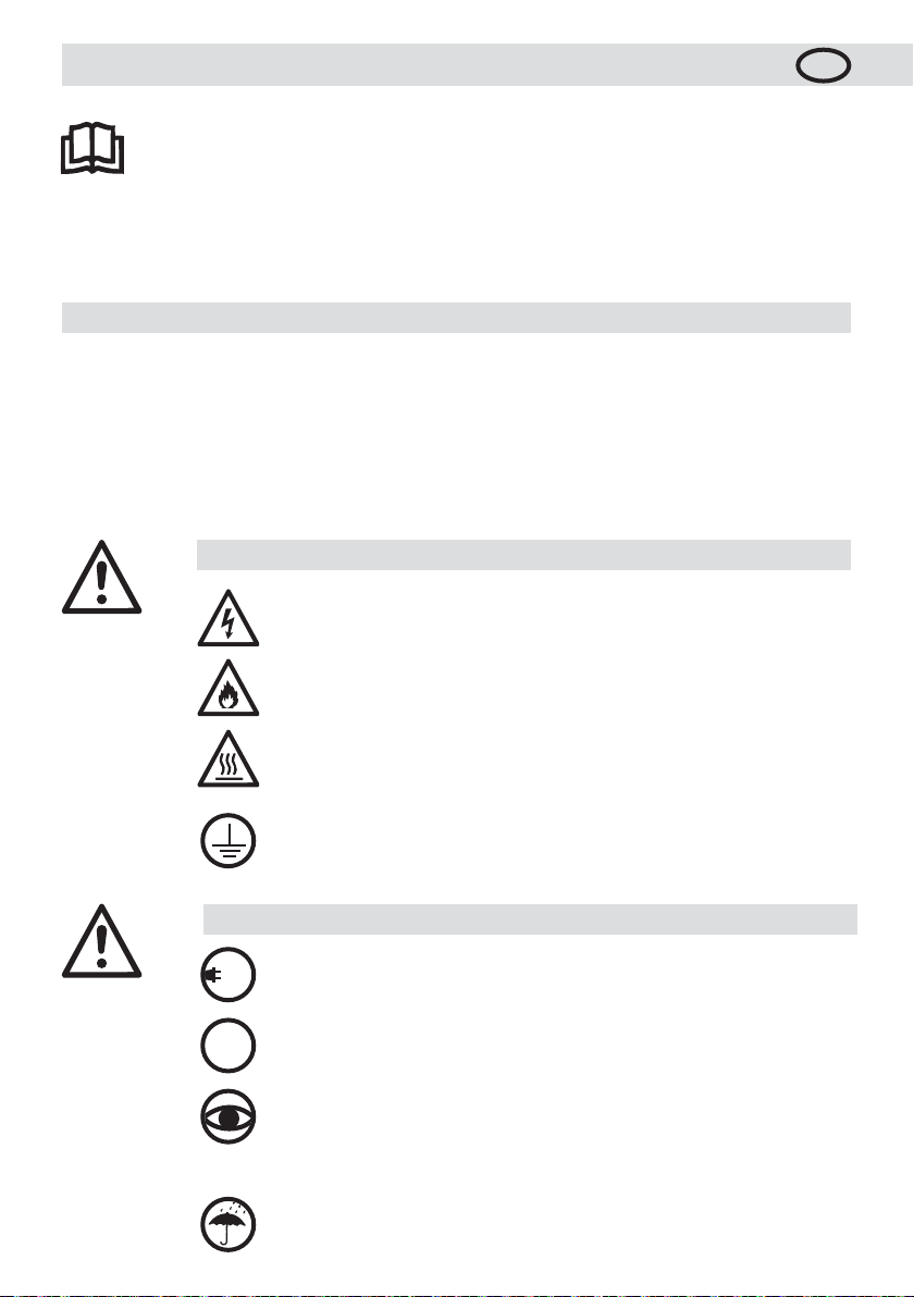
Warnung
D
Vorsicht
230
120
FI
Lebensgefahr beim Öffnen des Gerätes da spannungsführende
Anschlüsse freigelegt werden. Vor dem Öff
Steckdose ziehen.
Feuer- und Explosionsgefahr bei unsachgemässem Ge brauch von Heissluftgeräten,
besonders in der Nähe von brennbaren Materialien und explosiven Gasen.
Verbrennungsgefahr! Heizelementrohr und Düse nicht in heissem Zustand berühren.
Gerät abkühlen lassen.
Heissluftstrahl nicht auf Personen oder Tiere richten.
Gerät an eine Steckdose mit Schutzleiter anschliessen. Jede Unterbrechung des
Schutzleiters innerhalb oder ausserhalb des Gerätes ist gefährlich!
Nur Verlänge rungs kabel mit Schutzleiter verwenden!
Nennspannung, die auf dem Gerät angegeben ist, muss mit der Netzspannung
übereinstimmen. Bei Netzausfall Heissluftgebläse ausfahren.
FI-Schalter beim Einsatz des Gerätes auf Baustellen ist für den Personenschutz
dringend erforderlich.
Gerät muss beobachtet betrieben werden. Wärme kann zu brennbaren Materialien
gelangen, die sich ausser Sichtweite befinden.
Gerät darf nur von ausgebildeten Fachleuten oder unter deren Aufsicht benützt
werden. Kindern ist die Benützung gänzlich untersagt.
Gerät vor Feuchtigkeit und Nässe schützen.
nen des Gerätes Netzstecker aus der
Komponenten und
3
Konformität
Leister Technologies AG, Galileo-Strasse 10, CH-6056 Kaegiswil/Schweiz bestätigt, dass dieses Produkt in
der von uns in Verkehr gebrachten Ausführung die Anforderungen der folgenden EG-Richtlinien erfüllt.
Richtlinien: 2006/42, 2004/108, 2006/95, 2011/65
Harmonisierte Normen: EN 12100, EN 55014-1, EN 55014-2, EN 61000-3-2, EN 61000-3-3,
EN 62233, EN 60335-2-45, EN 50581
Kaegiswil, 27.05.2015
Bruno von Wyl, CTO Andreas Kathriner, GM
Entsorgung
Elektrowerkzeuge, Zubehör und Verpackungen sollen einer umweltgerechten Wiederverwertung
zugeführt werden. Nur für EU-Länder: Werfen Sie Elektrowerkzeuge nicht in den Hausmüll ! Gemäß
der Europäischen Richtlinie 2002/96/EG über Elektro- und Elektronik-Altgeräte und ihrer Um setzung
in nationales Recht müssen nicht mehr gebrauchsfähige Elektrowerkzeuge getrennt gesammelt und
einer umweltgerechten Wiederverwertung zugeführt werden.
Technische Daten
Spannung V~
Frequenz Hz
Leistung W
Temperatur °C
Luftmenge l/min.
Antrieb m/min.
Emissionspegel LpA(dB)
Schweissnahtbreite mm
Masse L × B × H mm
Gewicht kg
Konformitätszeichen
Schutzklasse I
Technische Änderungen vorbehalten
Anschlussspannung nicht umschaltbar
4
UNIPLAN S / UNIFLOOR S
230 120 100
50 / 60 50 / 60 50 / 60
2300 1800 1500
20 – 620 20 – 620 20 – 620
max. 300 max. 250 max. 250
1.0 – 7.5 1.0 – 7.5 1.0 – 7.5
67 65 65
UNIPLAN S UNIFLOOR S
20 oder 30
420 × 270 × 210 420 × 270 × 215
11.5 14.0
2 2
1 1
Zubehör UNIPLAN S
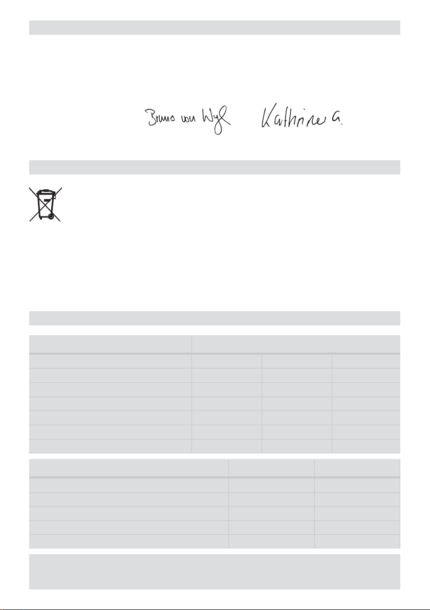
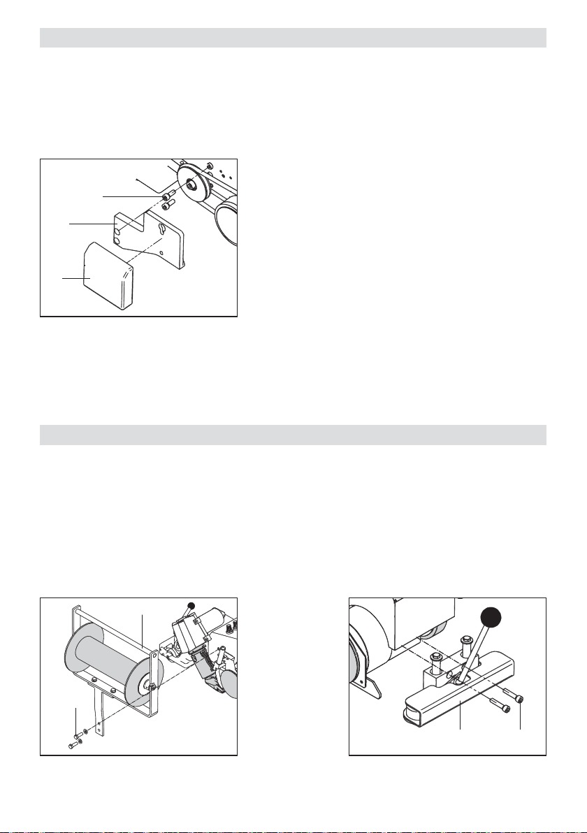
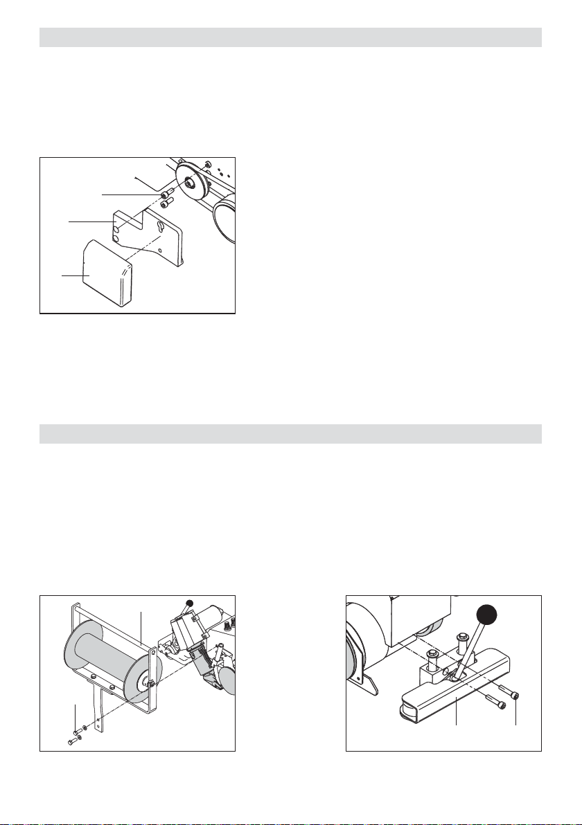
• Montage Zusatzgewicht:
– Zusatzgewichthalter (22) mit Zylinderschraube M8 × 20 (23) am Gerät UNIPLAN S befestigen.
– Zusatzgewicht (24) am Zusatzgewichthalter (22) einhängen.
Zubehör Zusatzgewicht
23
22
24
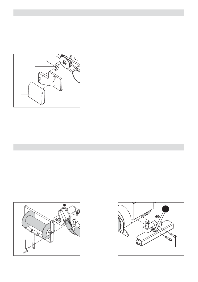
Zubehör UNIFLOOR S
• Betriebsbereitschaft Zubehör
Falls Zubehör Schweissdraht-Abrollvorrichtung (25) und Abhebevorrichtung (28) vorhanden:
– Schweissdraht-Abrollvorrichtung (25) mit Zylinderschraube M8 × 20 (26) am Gerät UNIFLOOR S
montieren.
– Abhebevorrichtung (28) mit Zylinderschraube Innensechskant M6 × 30 (27) montieren.
Zubehör
Schweissdraht-Abrollvorrichtung
25
26
Zubehör
Abhebevorrichtung
2728
5
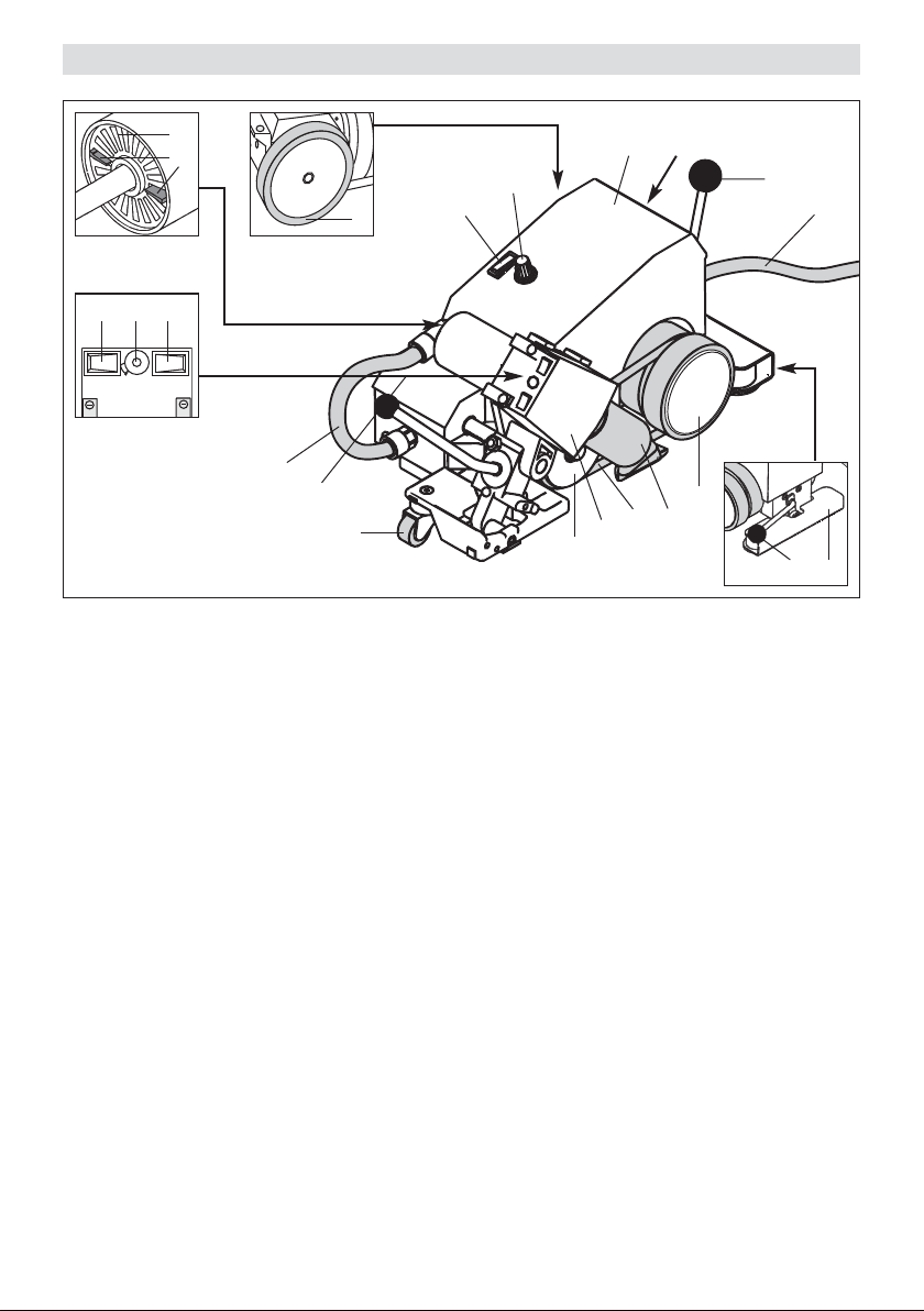
Gerätebeschreibung UNIPLAN S
12
13
17 18 19
1
203
Haupt-Komponenten
1 Gehäuse/Fahrgestell
2 Netzanschlussleitung
3 Heissluftgebläse
4 Schweissdüse
5 Verbindungsschlauch
6 Antriebs-/Andrückrolle
7 Niederhalterriemen
8 Umlenkrolle
9 Antriebsrolle
10 Lenkrolle
11 Abhebevorrichtung
12 Luftfilter
13 Manueller Luftschieber
21
1
16
9
15
14
2
5
20
10
3
8
6
4
7
1114
Bedienerelemente
14 Hebel Abhebevorrichtung
15 Antriebsschalter
16 Potentiometer für
Schweissgeschwindigkeit
17 Gebläseschalter
18 Potentiometer für Lufttemperatur
19 Zweistufenschalter für Lufttemenge
20 Schwenkhebel
21 Sicherung
T 1.0 A 230 V~
T 1.2 A 120 V~
Bedienung UNIPLAN S
Betriebsbereitschaft
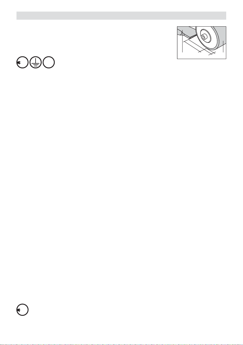
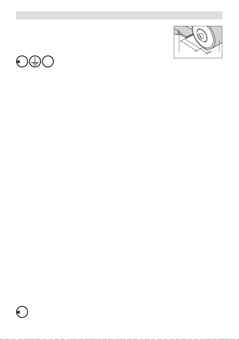
• Vor Inbetriebnahme Netzanschlussleitung (2) und Stecker sowie
Verlängerungskabel auf elektrische und mechanische Beschädigung überprüfen.
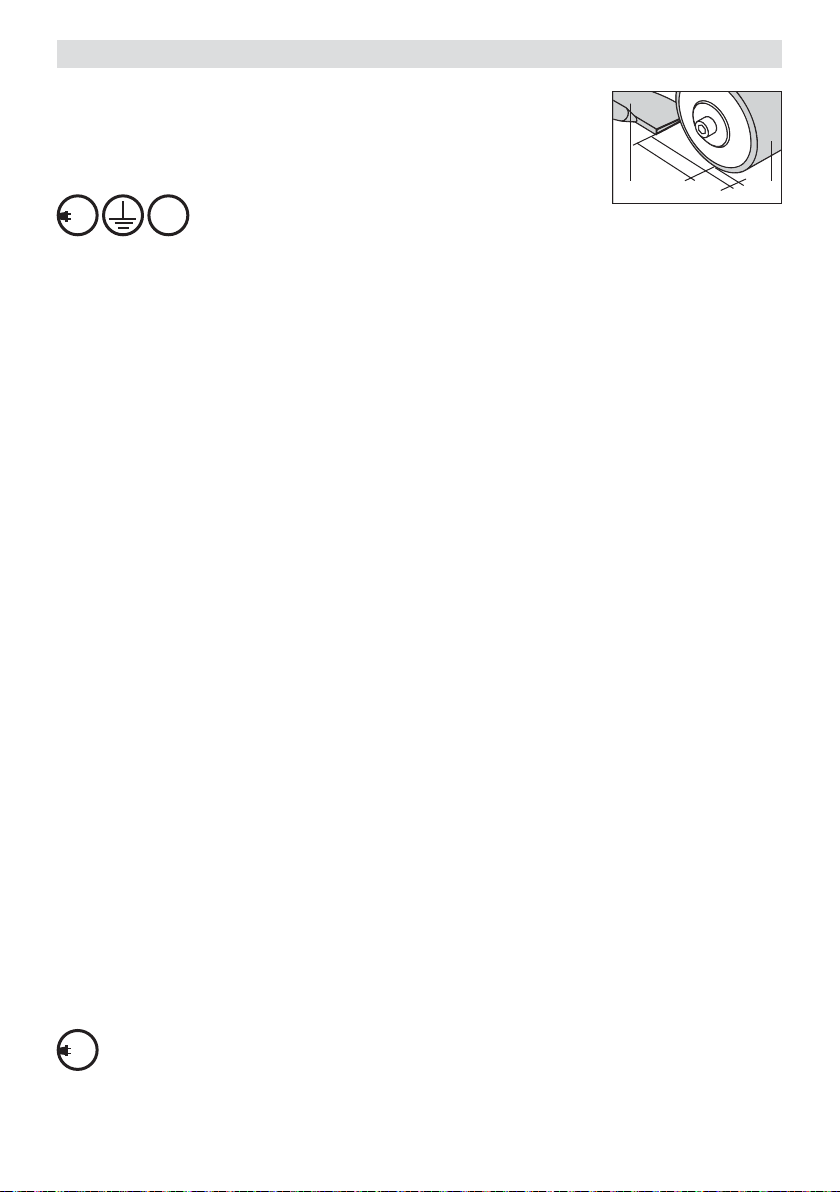
• Grundeinstellung der Düse kontrollieren (siehe Bild).
230
400
Gerät an Nennspannung anschliessen.
FI
Nennspannung, die auf dem Gerät angegeben ist,
muss mit der Netzspannung übereinstimmen.
Bei Netzausfall Heissluftgebläse ausfahren.
40 – 50mm
4
1–2 mm
6
Arbeitshinweise
• Testschweissung gemäss Schweissanleitung des Materialherstellers und nationalen Normen oder Richtlinien vor-
nehmen. Testschweissung prüfen. Schweisstemperatur (Schweissparameter) nach Bedarf anpassen.
Gerätepositionierung
• Heissluftgebläse (3) mit Schwenkhebel (20) bis zum Anschlag hochschwenken.
•
Abhebevorrichtung (11) mittels Hebel Abhebevorrichtung (14) betätigen, so dass Antriebs-/Andrückrolle (6)
sowie Antriebs rolle (9) im Leerlauf sind.
• Schweissautomat auf der Überlappung des Schweissmaterials positionieren. Dabei muss die Aussenkante der
Antriebs-/Andrückrolle (6) mit der Überlappungskante des Schweissmaterials übereinstimmen.
• Abhebevorrichtung (11) mittels Hebel Abhebevorrichtung (14) betätigen, so dass der Schweissautomat
fahrbereit ist.
Schweissparameter
• Potentiometer für Geschwindigkeit (16) auf gewünschten Wert einstellen.
• Potentiometer für Lufttemperatur (18) auf gewünschten Wert einstellen.
• Gebläseschalter (17) einschalten, Zweistufenschalter für Luftmenge (19) auf Stufe 3 und ca. 5 Minuten
aufheizen.
• Wichtig: Unterspannung
Wird die maximale Temperatur nicht erreicht, Luftmenge mit Zweistufenschalter für Luftmenge (19) und
Manuellem Luftschieber (13) reduzieren.
• Der Anpressdruck erfolgt durch das Eigengewicht des Heissluft-Schweissautomaten. Bei Bedarf das Zubehör
Zusatzgewicht verwenden (siehe Montage Zusatzgewicht, Seite 5).
Schweissablauf
• Heissluftgebläse (3) mit Schwenkhebel (20) bis zum Anschlag einschwenken und gleichzeitig Antriebsschalter (15)
einschalten (Schweissvorgang beginnt).
• Schweissvorgang kontrollieren. Bei Bedarf Schweissgeschwindigkeit mit Potentiometer (16) korrigieren.
Schweissautomat am Fahrgestell, entlang der Überlappung führen.
• Nach der Schweissung Heissluftgebläse (3) mit Schwenkhebel (20) bis zum Anschlag hochschwenken.
• Antriebsschalter (15) ausschalten.
• Nach Beendigung der Schweissarbeiten Potentiometer für Lufttemperatur (18) auf Null stellen, damit das
Heissluftgebläse (3) abgekühlt wird . Danach Gebläseschalter (17) ausschalten.
230
Netzanschlussleitung (2) vom elektrischen Netz trennen.
400
7

Gerätebeschreibung UNIFLOOR S
12
11
15 16 17
1
203
Abdeckung geönet
14
1
21
13
7
2
19
18
5
9
8
10
20
4
3
6
Detail A
Abdeckung
geschlossen
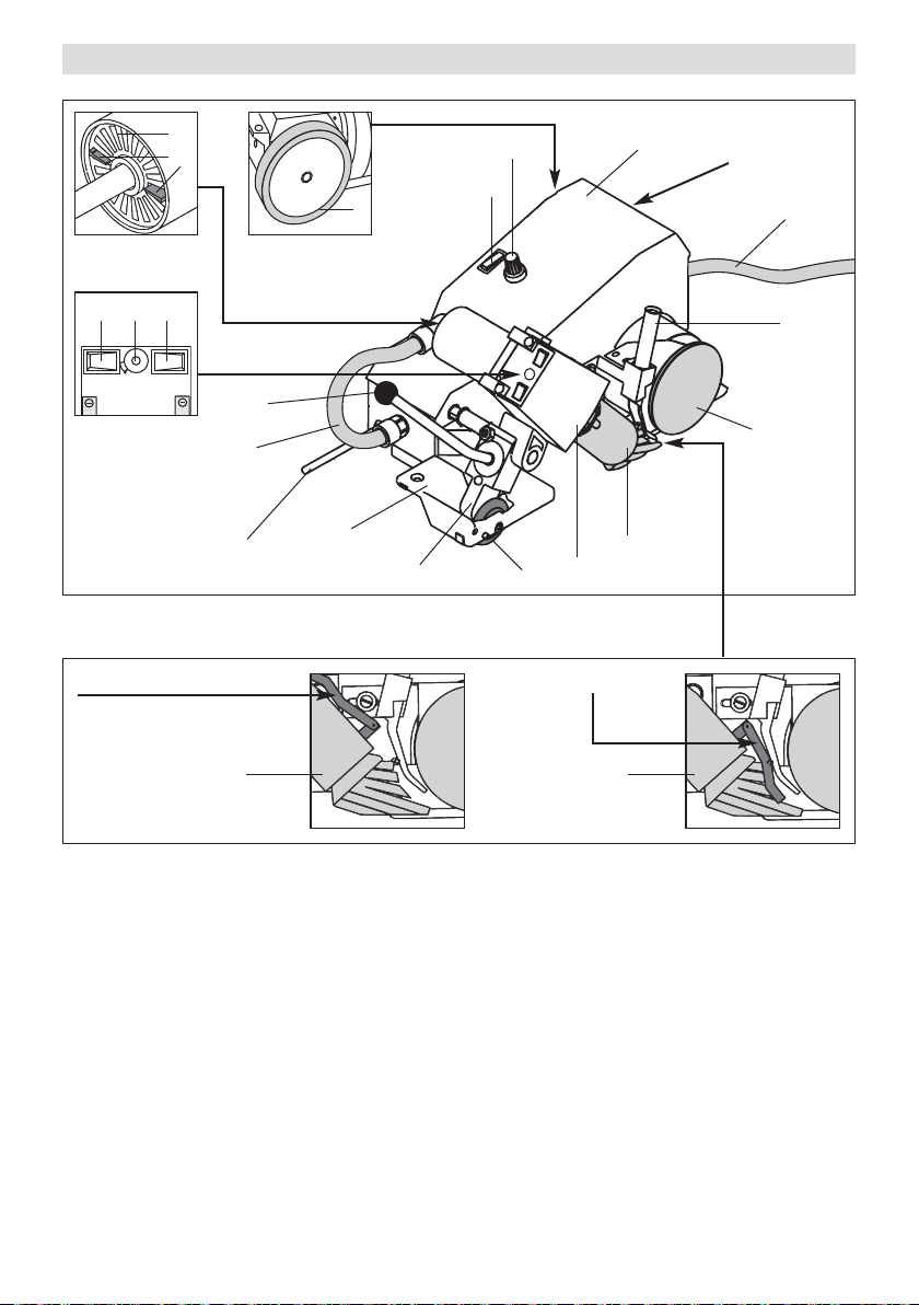
Haupt-Komponenten
1 Gehäuse
2 Netzkabel
3 Heissluftgebläse
4 Schweissdüse mit Abdeckung
5 Verbindungsschlauch
6 Drahtandrückrolle
7 Antriebsrolle
8 Fahrgestell
9 Wandabschalter
10 Lagerbock
11 Manueller Luftschieber
12 Luftfilter
8
4
4
Bedienerelemente
13 Antriebsschalter
14 Potentiometer für Schweissgeschwindigkeit
15 Gebläseschalter
16 Potentiometer für Lufttemperatur
17 Zweistufenschalter für Luftmenge
18 Schwenkhebel
Führungseinrichtung
19 Drahtführungsrohr
20 Führungsrolle
21 Sicherung
T 1.0 A 230 V~
T 1.2 A 120 V~

Bedienung UNIFLOOR S
Betriebsbereitschaft
• Vor Inbetriebnahme Netzanschlussleitung (2) und Stecker sowie Verlängerungskabel auf elektrische und
mechanische Beschädigung überprüfen.
• Düseneinstellung kontrollieren:
Düse muss zum Grundmaterial und zum Schweissdraht eine Distanz von ca. 2–3mm haben.
• Beim Verschweissen von Linoleum Abdeckung an der Schweissdüse (4) herunter klappen (siehe Detail A;
Seite 8).
230
400
Gerät an Nennspannung anschliessen.
FI
Nennspannung, die auf dem Gerät angegeben ist, muss mit der Netzspannung übereinstimmen.
Bei Netzausfall Heissluftgebläse ausfahren.
Arbeitshinweise
• Testschweissung gemäss Schweissanleitung des Materialherstellers und nationalen Normen oder Richtlinien vor-
nehmen. Testschweissung prüfen. Schweisstemperatur (Schweissparameter) nach Bedarf anpassen.
Gerätepositionierung
• Heissluftgebläse (3) mit Schwenkhebel (18) bis zum Anschlag hochschwenken.
• Schweissautomat über der zu verschweissenden Fuge positionieren.
• Schweissdraht durch Drahtführungsrohr (19) einführen, unter der Drahtandrück rolle (6) durchziehen und in
Fuge einlegen.
• Führungsrolle (20) muss in der Schweissfuge laufen.
Schweissparameter
• Potentiometer für Geschwindigkeit (14) auf gewünschten Wert einstellen.
• Potentiometer für Lufttemperatur (16) auf gewünschten Wert einstellen.
• Gebläseschalter (15) einschalten, Zweistufenschalter für Luftmenge (17) auf Stufe 3 und ca. 5 Minuten
aufheizen.
• Wichtig: Unterspannung
Wird die maximale Temperatur nicht erreicht, Luftmenge mit Zweistufenschalter für Luftmenge (17) und
Manuellem Luftschieber (11) reduzieren.
• Der Anpressdruck erfolgt durch das Eigengewicht des Heissluft-Schweissautomaten.
Schweissablauf
• Heissluftgebläse (3) mit Schwenkhebel (18) bis zum Anschlag einschwenken und gleichzeitig Antriebs-
schalter (13) einschalten (Schweissvorgang beginnt).
• Schweissvorgang kontrollieren:
– Führungsrolle (20) muss in der Fuge laufen
– Schweisswulst muss sichtbar sein. Bei Bedarf
•
Wandabschalter (9)
Bei Berührung der Wand schalten Antrieb und Heizung automatisch aus.
•
Nach der Schweissung Heissluftgebläse (3) mit Schwenkhebel (18) bis zum Anschlag
• Antriebsschalter (13) ausschalten. Schweiss-Schnur abschneiden, Schweissautomat nach Bedarf neu positio-
nieren.
• Nach Beendigung der Schweissarbeiten Potentiometer für Lufttemperatur (16) auf Null stellen, damit das
Heissluftgebläse (3) abgekühlt wird. Danach Gebläseschalter (15) ausschalten.
230
Netzanschlussleitung (2) vom elektrischen Netz trennen.
400
Schweissgeschwindigkeit mit Potentiometer (14) korrigieren.
hochschwenken.
9

Zubehör
• Es darf nur Leister-Zubehör verwendet werden.
• Zusatzgewicht mit Halterung für UNIPLAN S
• Schweissdraht-Abrollvorrichtung für UNIFLOOR S
• Abhebevorrichtung für UNIFLOOR S
Schulung
• Leister Technologies AG und deren autorisierte Service-Stellen bieten kostenlos Schweiss kurse und Einschulungen an.
• Informationen unter www.leister.com.
Wartung
• Luftfilter (12) des Gerätes ist bei Verschmutzung mit einem Pinsel zu reinigen.
• Schweissdüse (4) mit Drahtbürste reinigen.
• Netzanschlussleitung (2) und Stecker auf elektrische und mechanische Beschädigung überprüfen.
Service und Reparatur
• Kohlenstand der Motoren nach ca. 1'000 Betriebsstunden durch Ihre Service-Stelle kontrollieren lassen.
• Reparaturen sind ausschliesslich von autorisierten Leister-Service-Stellen ausführen zu lassen. Diese gewähr-
leisten innert 24 Stunden einen fachgerechten und zuverlässigen Reparatur-Service mit Original-Ersatzteilen
gemäss Schaltplänen und Ersatzteillisten.
Gewährleistung
• Für dieses Gerät gelten die vom direkten Vertriebspartner/Verkäufer gewährten Garantie- oder Gewährleistungs-
rechte ab Kaufdatum. Bei einem Garantie- oder Gewährleistungsanspruch (Nachweis durch Rechnung oder Lieferschein) werden Herstellungs- oder Verarbeitungsfehler vom Vertriebspartner durch Ersatzlieferung oder
Reparatur beseitigt. Heizelemente sind von der Gewährleistung oder Garantie ausgeschlossen.
• Weitere Garantie- oder Gewährleistungsansprüche werden im Rahmen des zwingenden Rechts ausgeschlossen.
• Schäden, die auf natürliche Abnutzung, Überlastung oder unsachgemässe Behandlung zurückzuführen sind, wer-
den von der Gewährleistung ausgeschlossen.
• Keine Garantie- oder Gewährleistungsansprüche bestehen bei Geräten, die vom Käufer umgebaut oder verändert
wurden.
10
Operating Instructions (Translation of the original operating instructions)
Read the operating instructions carefully before starting
the device and keep them for future reference.
Leister UNIPLAN S; UNIFLOOR S
Automatic hot air welding machine
Application
• Leister UNIPLAN S; Automatic overlap welding machine (Welding seam width 20 or 30 mm
Overlap and tape welding of coated fabrics, foils and membranes made from PVC-P, PE, ECB, CSPE, EPDM, as
well as PE woven materials for truck covers, tents, covers for agriculture and construction, biotopes, swimming
pools, awnings, boat covers, inflatable boats, billboards, banners.
• Leister Unifloor S; Automatic flooring welding machine
Welding of PVC coverings and melt welding of linoleum floor coverings.
Warning
Danger ! Unplug the tool before opening it, as live components and connections
are exposed.
Incorrect use of hot air tools can present a fire and explosion hazard, particularly
in the proximity of flammable materials and explosive gases.
GB
Caution
230
120
FI
Danger of getting burned! Do not touch the heater tube and nozzle when they are
hot. Let the tool cool down. Do not point the hot air flow in the direction of people
or animals.
Only connect the tool to a receptacle outlet with protective earth conductor.
Any disconnection of the protective earth conductor, in or outside the tool is
dangerous ! Only use extension lead with a protective earth conductor.
The rated voltage stated on the tool must correspond with the mains voltage.
Extract hot-air blower in case of power breakdown.
For personal protection, we strongly recommend the tool to be connected to an
RCCB (Residual Current Circuit Breaker) before using it on construction sites.
The device must not be left unattended when in use.
Heat can reach combustible materials which are out of sight.
The device may only be used by trained personnel or under their supervision. Children may not use the device under any circumstances.
Protect the tool from damp and wet.
11
Conformity
Leister Technologies AG, Galileo-Strasse 10, CH-6056 Kaegiswil/Switzerland confirms that this product in
the version put into circulation by us, fulfils the requirements of the following EU directives.
Directives: 2006/42, 2004/108, 2006/95, 2011/65
Harmonised standards: EN 12100, EN 55014-1, EN 55014-2, EN 61000-3-2, EN 61000-3-3,
EN 62233, EN 60335-2-45, EN 50581
Kaegiswil, 27.05.2015
Bruno von Wyl, CTO Andreas Kathriner, GM
Disposal
Power tools, accessories and packaging should be recycled. For EU countries only: do not dispose
of power tools in your household rubbish! According to the European Directive 2002/96 on waste electrical and electronic equipment and its implementation in national law, power tools which can no longer
be used must be collected separately and recycled.
Technical Data
UNIPLAN S / UNIFLOOR S
Voltage V~
Frequency Hz
Power consumption W
Temperature °C
Air flow l/min.
Drive speed m/min.
Noise emission level LpA(dB)
Welding seam width mm
Dimensions l × w × h mm
Weight kg
Conformity mark
Protection class I
Technical data and specifications are subject to change without prior notice.
Mains voltage cannot be switched over.
12
230 120 100
50 / 60 50 / 60 50 / 60
2300 1800 1500
20 – 620 20 – 620 20 – 620
max. 300 max. 250 max. 250
1.0 – 7.5 1.0 – 7.5 1.0 – 7.5
67 65 65
UNIPLAN S UNIFLOOR S
20 or 30
420 × 270 × 210 420 × 270 × 215
11.5 14.0
2 2
1 1
Accessories
• Assembly of additional weight
– Fasten the additional weight holder (22) to the UNIPLAN S machine with cheese head screw M8 × 20 (23).
– Attach the additional weight (24) to the additional weight holder (22).
Additional weight accessories
22
24
UNIPLAN S
23
Accessories UNIFLOOR S
• Operational condition: Accessories
If the welding rod de-reeler (25) and lifting device (11) are available:
– Attach welding rod de-reeler (25) to the Unifloor S machine using cheese head screw M8 × 20 (26).
– Attach lifting device (11) using socket head cap scew M6 × 30 (27).
Accessory
Welding rod de-reeler
25
26
Accessory
Lifting device
2728
13

Tool description UNIPLAN S
12
13
17 18 19
1
203
Main components
1 Housing/chassis
2 Power supply cord
3 Hot air blower
4. Welding nozzle
5 Connection hose
6 Drive/pressure roller
7 Pressure belt
8 Guide roller
9 Drive roller
10 Steering roller
11 Lifting device
12 Air filter
13 Manual air valve
21
1
16
9
15
14
2
5
20
10
3
8
6
4
7
1114
Operating components
14 Lifting device lever
15 Drive switch
16 Potentiometer for welding speed
17 Air blower switch
18 Potentiometer for air temperature
19 Two stage switch for airflow
20 Swivel lever
21 Fuse
T 1.0 A 230 V~
T 1.2 A 120 V~
Operation UNIPLAN S
Operating condition
•
Before putting into operation, check
extension cable for electrical and mechanical damage.
power supply cord
(2) and connector as well as
40 – 50mm
• Check the nozzle’s basic setting (see diagram).
230
400
Connect tool to rated voltage.
FI
Rated voltage stated on the device must correspond to line/mains voltage.
4
1–2 mm
6
Extract hot-air blower in case of power breakdown.
Operating Instructions
• Perform a test welding according to the welding instructions of the material manufacturer and the national
standards or guidelines. Check the test welding. Adapt the welding temperature (welding parameters) as
required.
Tool positioning
• Swivel hot air blower (3) using swivel lever (20) up to the stop.
• Operate lifting device (11) by means of lifting device lever (14) so that drive/pressure roller (6) and drive
roller (9) are at no-load.
• Position the automatic welding machine on the overlap of the material to be welded. The outside edge of
drive/pressure roller (6) must line up with the overlap edge of the material to be welded.
• Activate lifting device (11) by means of lifting device lever (14) so that the automatic welder is ready to run.
Welding parameters
• Set potentiometer for welding speed (16) to the required value.
• Set potentiometer for air flow (18) to the required value.
• Turn on air blower switch (17). Set the two stage switch for airflow (19) at setting 3 and heat up for about 5
minutes.
• Important: low voltage.
If the maximum temperature is not reached, reduce the airflow by means of the manual air valve (13) and two
stage switch for airflow (19).
• The contact pressure is effected through the weight of the automatic hot air welding machine itself. Use the
additional weight accessory as required (see assembly of additional weight, page 13).
Welding procedure
• Swivel the hot air blower (3) up to the stop using swivel lever (20) and at the same time turn on the drive
switch (15) (the welding process starts).
• Supervise the welding process. As necessary correct the welding speed with the potentiometer (16). Lead the
automatic welding machine by its chassis along the length of the overlap.
• When welding has finished, swing up the hot air blower (3) to the stop by means of the swivel lever (20).
• Switch off the drive switch (15).
• After completing welding work, set the potentiometer for air temperature (18) to zero, so that the hot air
blower (3) cools down. Then turn off the air blower switch (17).
230
Disconnect power supply cord (2) form the line/mains.
400
15
Tool description UNIFLOOR S
15 16 17
1
Cover open
203
12
11
14
1
21
13
7
2
19
18
5
9
8
10
20
4
3
6
Detail A
Cover closed
Main components
1 Housing
2 Power supply cord
3 Hot air blower
4 Welding nozzle with cover
5 Connection hose
6 Welding rod pressure roller
7 Drive roller
8 Chassis
9 Wall switch-off
10 Support bracket
11 Manual air valve
12 Air filter
16
4
4
Operating components
13 Drive switch
14 Potentiometer for welding speed
15 Air blower switch
16 Potentiometer for air temperature
17 Two stage switch for airflow
18 Swivel lever
Steering equipment
19 Welding rod guide tube
20 Guide roller
21 Fuse
T 1.0 A 230 V~
T 1.2 A 120 V~
Operation UNIFLOOR S
Operating condition
•
Before putting into operation, check
and mechanical damage.
• Check the nozzle setting:
the nozzle must maintain a distance from the base material and the welding rod of about 2-3 mm.
• When welding linoleum, lower the cover on to the welding nozzle (4) (see Detail A: page 16).
230
400
Connect tool to rated voltage.
FI
Rated voltage stated on the device must correspond to line/mains voltage.
Extract hot-air blower in case of power breakdown.
power supply cord
(2) and connector as well as extension cable for electrical
Operating Instructions
• Perform a test welding according to the welding instructions of the material manufacturer and the national
standards or guidelines. Check the test welding. Adapt the welding temperature (welding parameters) as
required.
Tool positioning
• Swivel hot air blower (3) up to the stop using swivel lever (19).
• Position the automatic welding machine over the joint to be welded.
• Insert the welding rod through the welding rod guide tube (19), pull it under the welding rod pressure
roller (6) and place it in the joint.
• The Guide roller (20) must run in the welding joint.
Welding parameters
• Set potentiometer for welding speed (14) to the required value.
• Set potentiometer for air temperature (16) to the required value.
• Turn on the air blower switch (15), set the two stage switch for airflow (17) at setting 3 and heat up for
about 5 minutes.
• Important: low voltage.
If the maximum temperature is not reached, reduce the airflow by means of the manual air valve (11) and the
two stage switch for air flow (17).
• The contact pressure is effected through the weight of the automatic hot air welding machine itself.
Welding procedure
• Swivel hot air blower (3) up to the stop using swivel lever (18) and at the same time turn on the drive
switch (13) (The welding process starts).
• Supervise the welding process:
– Guide roller (20) must run in the joint.
–
The welding bead must be visible. If necessary adjust the welding parameters using the potentiometer (14).
• Wall switch-off (9)
When contact is made with the wall, the drive and heater are switched off automatically.
• When welding is finished, swing up the hot air blower (3) to the stop by means of swivel lever (18).
• Switch off the drive switch (13). Cut off the welding rod. Re-position the automatic welding machine as
necessary.
• After completing work, set potentiometer for air temperature (16) to zero so that hot air blower (3) cools
down. Then turn off the air blower switch (15).
230
Disconnect power supply cord (2) form the line/mains.
400
17

Accessories
• Only Leister accessories should be used.
• Additional weight with holder for UNIPLAN S
• Welding rod de-reeler for UNIFLOOR S
• Lifting device for UNIFLOOR S
Training
•
Leister Technologies AG and its authorised Service Centres offer free welding courses and training.
•
Informationen below www.leister.com.
Maintenance
• Clean the tool's air filter (12) with a brush when dirty.
• Clean welding nozzle (4) with wire brush.
• Check power supply cord (2) and plug for electrical and mechanical damage
Service and repair
• Have your Service Centre check the motor brushes after about 1000 hours of operation.
• Repairs have to be carried out by authorised Leister Service Centres only. They guarantee, within 24 hours, a
correct and reliable repair service using original spare parts in accordance with the circuit diagrams and spare
parts lists.
Warranty
• For this tool, the guarantee or warranty rights granted by the relevant distributor/seller shall apply. In case
of guarantee or warranty claims any manufacturing or workmanship defects will either be repaired or replaced by the distributor at its discretion. Warranty or guarantee rights have to be verified by an invoice or
a delivery document. Heating elements shall be excluded from warranty or guarantee.
• Additional guarantee or warranty claims shall be excluded, subject to mandatory provisions of law.
• Warranty or guarantee shall not apply to defects caused by normal wear and tear, overload or improper
handling.
• Warranty or guarantee claims will be rejected for tools that have been altered or changed by the purchaser.
18
Istruzioni d’uso (Traduzione del manuale di istruzioni originale)
Prima della messa in funzione leggere attentamente queste istruzioni d'uso
e tenerle a disposizione per la consultazione
Leister UNIPLAN S; UNIFLOOR S
Apparecchio automatico per saldatura ad aria calda
Applicazioni
• Leister UNIPLAN S; Apparecchio automatico per la saldatura a sovrapposizione
(Larghezza della saldatura 20 oppure 30 mm)
Saldatura a sovrapposizione e saldatura di nastri per teloni in tessuto spalmato, foglie e manti per isolamento in
PVC-P, PE, ECB,CSPE, EPDM e nastri in tessuto spalmato con PE per camion, tende, coperture agricole, per edilizia,
per culture biologiche, piscine, coperture per barche, gommoni, teli pubblicitari, ecc.
• Leister Unifloor S; Apparecchio automatico per la saldatura di pavimenti.
Saldatura di pavimenti in PVC e saldatura per fusione di pavimentazioni in Linoleum.
Avvertenza
Pericolo letale: l'apparecchio contiene componenti sotto tensione. Prima di
aprire l'apparecchio, togliere la spina.
Pericolo d'incendio e di esplosione in caso di uso improprio degli apparecchi ad
aria calda, specialmente in prossimità di materiali infiammabili e di gas esplosivi.
I
Attenzione
230
120
FI
Attenzione alle scottature ! Non toccare il tubo contenente l'elemento riscaldante
e l'ugello quando sono ancora caldi. Lasciare rareddare l'apparecchio. Non dirigere
il getto di aria calda verso persone o animali.
Allacciare l'apparecchio ad una presa provvista di messa a terra.
Qualsiasi interruzione della messa a terra, interna od esterna allo apparecchio, è
pericolosa. Utilizzare solamente cavi di prolunga con filo di messa a terra.
La tensione nominale indicata sull'apparecchio deve corrispondere alla tensione
di rete. In caso di caduta di alimentazione, estrarre la ventola dell’aria calda.
Interruttore FI (salvavita) è assolutamente necessario quando l'apparecchio viene
usato in cantiere.
Sorvegliare sempre l'apparecchio durante l'uso.
Il calore può raggiungere materiali infiammabili che si trovano oltre il campo visivo.
La macchina deve essere utilizzata esclusivamente da personale specializzato
addestrato oppure sotto il controllo dello stesso.
È assolutamente vietato l’impiego da parte di bambini.
Proteggere l'apparecchio dall'umidità e dal bagnato.
19
Dichiarazione di conformità
Leister Technologies AG, Galileo-Strasse 10, CH-6056 Kaegiswil/Svizzera conferma che questo prodotto da
noi introdotto sul mercato soddisfa tutti i requisiti richiesti dalle seguenti direttive della CE.
Direttive: 2006/42, 2004/108, 2006/95, 2011/65
Norme armonizzate: EN 12100, EN 55014-1, EN 55014-2, EN 61000-3-2, EN 61000-3-3,
EN 62233, EN 60335-2-45, EN 50581
Kaegiswil, 27.05.2015
Bruno von Wyl, CTO Andreas Kathriner, GM
Smaltimento
Avviare ad un riciclaggio rispettoso dell’ambiente gli imballaggi, gli elettro utensili e gli accessori
dismessi. Solo per i Paesi della CE: Non gettare elettro utensili dismessi tra i rifiuti domestici !
Conformemente alla norma della direttiva 2002/96 sui rifiuti di apparecchiature elettriche
ed elettroniche (RAEE) ed all’attuazione del recepimento nel diritto nazionale, gli elettroutensili
diventati inservibili devono essere raccolti separatamente ed essere inviati ad una riutilizzazione
ecologica.
Dati tecnici
Tensione V~
Frequenza Hz
Potenza W
Temperatura °C
Quantità aria l/min.
Avanzamento m/min.
Emissione sonora LpA(dB)
Larghezza della saldatura mm
Dimensioni L × l ×a mm
Peso kg
Marchio di omologazione
Classe di protezione I
Ci riserviamo modifiche tecniche
Tensione di allacciamento non commutabile
20
UNIPLAN S / UNIFLOOR S
230 120 100
50 / 60 50 / 60 50 / 60
2300 1800 1500
20 – 620 20 – 620 20 – 620
max. 300 max. 250 max. 250
1.0 – 7.5 1.0 – 7.5 1.0 – 7.5
67 65 65
UNIPLAN S UNIFLOOR S
20 oder 30
420 × 270 × 210 420 × 270 × 215
11.5 14.0
2 2
1 1
Accessori
• Montaggio peso supplementare
–
fissare il supporto del peso supplementare (22) con la vite cilindrica M8 × 20 (23) all’apparecchio
UNIPLAN S.
– Agganciare il peso supplementare (24) all’apposito supporto.
Accessorio peso supplementare
22
24
UNIPLAN S
23
Accessori UNIFLOOR S
• Accessori per la messa in funzione
Qualora ci siano a disposizione gli accessori: dispositivo di srotolamento del filo (25) e quello per il
sollevamento (11):
– montare lo srotolatore (25) sull’apparecchio UNIFLOOR S mediante le viti cilindriche M8 × 20 (26),
– montare il dispositivo di sollevamento (11) con le viti a brugola M6 × 30 (27).
Accessorio
dispositivo di srotolamento
25
26
Accessorio
dispositivo di sollevamento
2728
21

Descrizione dell’apparecchio UNIPLAN S
12
13
17 18 19
1
203
5
Componenti principali
1 Carter / telaio
2
Linea di allacciamento alla rete
3 Soante aria calda
4 Ugello di saldatura
5 Cavo di collegamento
6 Rullo di pressione / azionamento
7 Cinghia premitelo
8 Rullo di rinvio
9 Rullo di traino
10 Rullo di guida apparecchio
11 Dispositivo di sollevamento
12 Filtro aria soante
13 Serranda manuale dell’aria
20
10
16
9
15
3
8
Elementi di servizio
14 Leva del dispositivo di sollevamento
15 Interruttore per l’azionamento
16 Potenziometro per la velocità di saldatura
17 Interruttore soante
18 Potenziometro per la temperatura dell’aria
19 Interruttore a 2 stadi quantità dell’aria
20 Leva di posizionamento
21 Fusibile
T 1.0 A 230 V~
T 1.2 A 120 V~
21
1
14
2
6
4
7
1114
Condizioni di utilizzo UNIPLAN S
Messa in funzione
• Prima della messa in funzione controllare il linea di allacciamento alla rete (2),
la spina e la prolunga, per accertarne l’integrità elettrica e meccanica.
• Controllare il posizionamento dell’uggello di saldatura (vedi figura).
230
400
Collegare l’apparecchio alla tensione nominale.
FI
La tensione nominale indicata sull'apparecchio deve corrispondere alla tensione di rete.
In caso di caduta di alimentazione, estrarre la ventola dell’aria calda.
40 – 50mm
4
–2mm
1
6
Instrucciones para la operación
• Efectuar una soldadura de prueba según las instrucciones de soldadura del fabricante y la normativa o directrices
nacionales. Examinar la soldadura de prueba. Adaptar la temperatura de soldadura (parámetros de soldadura) si
fuese preciso.
Posizionamento dell’apparecchio
• Sollevare il soante aria calda (3) tramite la leva di inserimento / disinserimento (20) fino al fermo.
• Inserire il dispositivo di sollevamento (11) mediante l’apposita leva (14), anchè sia il rullo di pressione /
azionamento (6) che il rullo di traino (9) siano liberi.
• Posizionare l’apparecchio automatico fra i due lembi da saldare. ll bordo esterno del rullo di pressione /
azionamento (6) deve corrispondere esattamente con il bordo dei telo da saldare.
• Mediante la leva del dispositivo di sollevamento (11) l’apparecchio viene liberato ed ora può essere spostato.
Parametri di saldatura
• Inserire il valore desiderato al potenziometro per la velocità di saldatura (16).
• Inserire il valore desiderato al potenziometro per la temperatura dell’aria (18).
• Inserire l’interruttore del soante (17), porre l’interruttore a 2 stadi per la quantità d’aria (19) sul livello 3
e riscaldare per ca. 5 minuti.
• Importante : Tensione di rete insuciente
Qualora non si raggiunga la massima temperatura, tramite la serranda manuale dell’aria (13) e l’interruttore
a 2 stadi per la quantità dell’aria (19) ridurre la portata dell’aria.
• La pressione sulla saldatura avviene tramite il peso dell’apparecchio automatico stesso. Se necessario usare
come accessorio il peso supplementare (vedi montaggio peso supplementare a pag. 21).
Andamento della saldatura
• Mediante la leva di inserimento / disinserimento (20) abbassare spostanddo il soante aria calda (3) fino al
fermo, contemporaneamente inserire l’interruttore per l’azionamento (15) (la saldatura ha inizio).
• Controllare l’andamento della saldatura.
Se necessario, correggere la velocità di saldatura tramite il potenziometro (16).
Condurre l’apparecchio automatico lungo la sovrapposizione dei lembi da saldare.
• Eseguita la saldatura sollevare il soante aria calda (3) tramite la leva di inserimento /disinserimento (20)
fino al fermo.
• Disinserire l’interruttore per l’azionamento (15).
• Terminate le saldature, occorre portare il potenziometro della temperatura dell’aria (18) sullo zero, anchè il
soante dell’aría calda (3) si possa rareddare. Disinserire quindi l’interruttore del soante (17).
230
Separare Linea di allacciamento alla rete (2) dalla rete elettrica.
400
23

Descrizione dell’apparecchio UNIFLOOR S
12
11
15 16 17
1
203
copertura sollevata
14
1
21
13
7
2
19
18
5
9
8
10
20
4
3
6
Dettaglio A
copertura abbassata
4
Componenti principali
1 Carter
2
Linea di allacciamento alla rete
3 Soante aria calda
4 Ugello di saldatura con copertura
5 Cavo di collegamento
6 Rullo di pressione sul filo a saldare
7 Rullo di azionamento
8 Telaio
9 Interruttore a parete
10 Supporto cuscinetto
11 Serranda manuale dell’aria
12 Filtro aria soante
24
4
Elementi di servizio
13 Interruttore per l’azionamento
14 Potenziometro per la velocità di saldatura
15 Interruttore soante
16 Potenziometro per la temperatura dell’aria
17 Interruttore a 2 stadi quantità dell’aria
18 Leva di inserimento / disinserimento
Dispositivi per la guida
19 Tubo guida filo di saldatura
20 Rullo di guida
21 Fusibile
T 1.0 A 230 V~
T 1.2 A 120 V~

Condizioni di utilizzo UNIFLOOR S
Messa in funzione
• Prima della messa in funzione controllare il linea di allacciamento alla rete (2), la spina e la prolunga, per
accertarne l’integrità elettrica e meccanica.
• Controllare il posizionamento dell’uggello di saldatura.:
esso deve trovarsi ad una distanza di ca. 2 –3 mm. sia dal filo di saldatura che dal materiale da saldare.
• Per saldare il Linoleum occorre abbassare la copertura sull’uggello di saldatura (4) (vedi dettaglio A - pag. 24).
230
400
Collegare l’apparecchio alla tensione nominale.
FI
La tensione nominale indicata sull'apparecchio deve corrispondere alla tensione di rete.
In caso di caduta di alimentazione, estrarre la ventola dell’aria calda.
Instrucciones para la operación
• Efectuar una soldadura de prueba según las instrucciones de soldadura del fabricante y la normativa o directrices
nacionales. Examinar la soldadura de prueba. Adaptar la temperatura de soldadura (parámetros de soldadura) si
fuese preciso.
Posizionamento dell’apparecchio
• Sollevare il soante aria calda (3) tramite la leva di inserimento / disinserimento (18) fino al fermo.
• Posizionare l’apparecchio automatico sulla fuga da saldare.
• Introdurre il filo di saldatura nell’apposito tubo di guida (19) e tirandolo attraverso il rullo di pressione (6) posarlo
sulla fuga di saldatura.
• Il rullino di guida (29) deve essere introdotto e camminare nella fuga di saldatura.
Parametri di saldatura
• Inserire il valore desiderato al potenziometro per la velocità di saldatura (14).
• Inserire il valore desiderato al potenziometro per la temperatura dell’aria (16).
• Inserire l’interruttore del soante (15), porre l’interruttore a 2 stadi per la quantità d’aria (17) sul livello 3
e riscaldare per ca. 5 minuti.
• Importante : Tensione di rete insuciente
Qualora non si raggiunga la massima temperatura, tramite la serranda manuale dell’aria (11) e l’interruttore
a 2 stadi per la quantità dell’aria (17) ridurre la portata dell’aria.
• La pressione sulla saldatura avviene tramite il peso dell’apparecchio automatico stesso.
Andamento della saldatura
• Mediante la leva di inserimento / disinserimento (19) spostare il soffiante aria calda (3) fino al fermo,
contemporaneamente inserire l’interruttore per l’azionamento (13) (la saldatura [la inizio).
• Controllare l’andamento della saldatura :
– il rullino di guida (20) deve scorrere nell’apposita fuga di saldatura.
– il cordone di saldatura deve essere visibile. Se necessario correggere i paramentri della velocità di saldatura al
potenziometro (14).
• Interruttore a parete (9).
Non appena l’apparecchio entra in contatto con la parete, vengono disinseriti riscaldamento ed azionamento.
• Eseguita la saldatura, sollevare il soante aria calda (3) tramite la leva di inserimento / disinserimento (18)
fino al fermo.
• Disinserire l’interruttore per l’azionarnento (13).
Tranciare il cordone di saldatura, e se necessario ripozizionare il saldatore automatico.
• Terminate le saldature, occorre portare il potenziometro della temperatura dell’aria (16) sullo zero, anché il
soante dell’aria calda (3) si possa rareddare. Disinserire quindi l’interruttore del soante (15).
230
Separare Linea di allacciamento alla rete (2) dalla rete elettrica.
400
25

Accessori
• Devono essere utilizzati unicamente accessori Leister.
• Peso supplementare con supporto per UNIPLAN S.
• Dispositivo di srotolamento per UNIFLOOR S.
• Dispositivo di sollevamento per UNÌFLOOR S.
Corsi di addestramento
•
Leister Technologies AG e i centri d’assistenza autorizzati offrono corsi di saldatura e corsi di formazione gratuiti.
• Informazioni alla pagina www.leister.com.
Manutenzione
• Pulire il filtro dell’aria del soante (12).
• Pulire con una spazzola in fili di ottone l’ugello di saldatura (4).
• Controllare sempre che il linea di allacciamento alla rete (2) e la spina non abbiano danni meccanici ed elettrici.
Assistenza e riparazioni
• L’apparecchio deve essere controllato presso i punti di assistenza autorizzati Leister. Dopo 1000 ore di esercizio,
i carboncini devono essere controllati dai punti assistenza Leister.
• Le riparazioni devono essere eseguite esclusivamente presso i punti assistenza autorizzati Leister. Questi sono
in grado di garantire riparazioni sicure e adabili con ricambi secondo le liste di ricambio e gli schemi elettrici
originali in 24 ore.
Garanzia legale
• A questo prodotto si applicano i diritti previsti per la garanzia concessi dal partner di distribuzione/rivenditore
diretto, a partire dalla data di acquisto. In caso di ricorso alla garanzia (fanno fede la fattura o la bolla di consegna), sono previste la fornitura sostitutiva o la riparazione di difetti di fabbricazione o di lavorazione a cura
del partner di distribuzione. La garanzia non si applica agli elementi riscaldanti.
• È esclusa qualsiasi ulteriore garanzia non espressamente prevista dalle vigenti norme di diritto cogente.
• Sono esclusi dalla garanzia i danni riconducibili alla naturale usura, al sovraccarico o alla scorretta manipo-
lazione.
• Il ricorso alla garanzia decade per gli apparecchi sottoposti a modifiche o alterazioni da parte dell’acquirente.
26
 Loading...