

Leister Twinmat Operating Instructions Manual
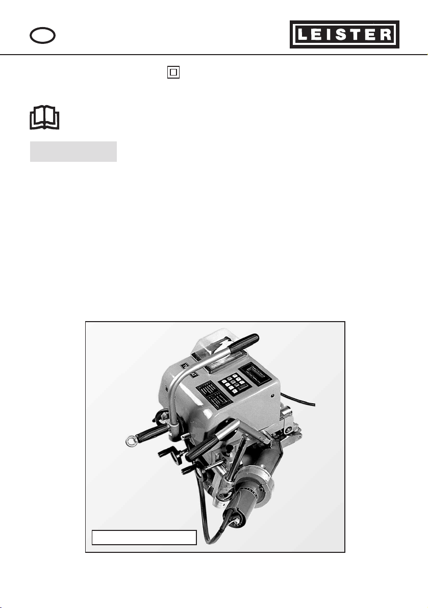
LEISTER Twinmat
Automatic wedge welding machine
Please read operating instructions carefully before use
and keep for further reference.
GB
OPERATING INSTRUCTIONS
The LEISTER Twinmat is an automatic wedge welding machine for overlap
welding of geomembrane liners for earthwork and civil engineering.
• Thermoplastic lining membranes • Type of seam
Polyvinyl chloride plasticised PVC-P Welding seams are
Polyethylene high density PE-HD produced in accordance
Polyethylene low density PE-LD with DVS 2225 part 1 and
Chlorinated polyethylene PE-C BAM.
Polypropylene PP Other dimensions are
Ethylene copolymer bitumen ECB possible on request.
Ethylene vinyl acetate E/VA
DVS: German Welding Association
BAM: Federal Institute for Materials Research and Testing, Berlin
APPLICATION
TWINMAT with printer
®
LEISTER Process Technologies, Riedstrasse, CH-6060 Sarnen/ Switzerland
Tel. +41- 41 662 74 74 Fax + 41- 41 662 74 16
www.leister.com sales@leister.com
2
WELDING Pages 11 – 12
•
welding preparation
•
welding procedure
•
welding tips
TRAINING Pages 12
MAINTENANCE Pages 12
SERVICE AND REPAIR Pages 12
NOTICE Pages 12
Authorized Service
Centre Pages 12
Contents:
APPLICATION Pages 1
WARNING Pages 2
CAUTION Pages 2
TECHNICAL DATA Pages 3
FUNCTIONS Pages 3 – 4
DESCRIPTION OF TOOL Pages 5 – 10
•
mechanics
•
key board
•
software system level
•
printer
Danger to life when opening the tool, as live components and connections ar exposed. Unplug the tool
before opening it.
Incorrect use of hot air blowers can cause fire and
explosion hazard, especially near combustible materials
and explosive gases.
The tool must be operated with supervision. Warmth
can reach combustible materials, which are out of sight.
For personal protection on building sites we strongly
recommend the tool be connected to a GFCI (Ground
Fault Circuit Interrupter) or a RCCB (Residual Current
Circuit Breaker) .
The voltage rating stated on the tool must correspond to
the line/mains voltage.
Do not touch the element housing and nozzle when
they are hot as they can cause burns. Let the tool cool
down. Do not point hot air flow in the direction of
people or animals.
Protect tool from damp and wet.
FI
230
400
WARNING
CAUTION

Electrical safety: double insulated
Voltage V~
Capacity W
Frequency Hz
Temperature °C
Air flow l/min.
Drive m/min.
Welding pressure N
Operating temp. °C
Size mm
Weight kg
230 or 400 ★
4600 or 5800
50 / 60
20 – 620 steplessly controlled
max. 500 manual air slide
0,5 – 5,0 steplessly controlled (tachogenerator)
max. 2500 steplessly adjustable
- 5 to 45
600 x 690 x 450
32,0
4M1Order No.
TECHNICAL DATA LEISTER Twinmat (4M1)
3
DESCRIPTIONS OF FUNCTIONS LEISTER Twinmat (4M1)
• Heating system ➝ The hot air temperature is electronically steplessly adjusta-
ble and electronically controlled for heating up the hot air wedge. Digital
display of SET and ACTUAL value. The flexible hot air wedge has three heat
zones:
Pre-heating, contact heating, material plasticising with hot air.
• Welding pressure ➝ steplessly adjustable, digital ACTUAL value display. The
welding pressure is transmitted via the toggle lever to the pressure rollers.
During the welding process the pressure is matched linearly to the change
in thickness of the membrane (e.g. T-joint).
• Drive ➝ electronically steplessly adjustable and electronically controlled. Digi-
tal display of SET and ACTUAL value. The power transmission works through a
three stage planetary gear. Should rippling occur in the laid-out geomembrane liners, the upper or lower drive/pressure roller can be switched over
alternatively.
★ Mains voltage cannot be switched over
• Monitoring the welding seam ➝ Contactless recording of the seam thickness
reduction data, which is displayed digitally for the welding operator during
the welding operation. Additionally, the seam thickness reduction is graphically recorded onto a paper print out continuously during the welding operation.
• Speed control system
The influence of weather such as sun, shade, wind and moisture, which cause
a temperature change in the lining membrane during the welding process,
can lead to weld faults. The TWINMAT speed control system interprets the data
from the continuous measurement of the welding seam geometry. Through
automatic adjustment of the welding speed, such weld faults are avoided.
The welding operation can be done either with or without the speed control
system. If the lower seam thickness reduction tolerance is exceeded, the
welding speed slows down automatically; if the upper seam thickness reduction tolerance is exceeded, the welding speed is increased.
DESCRIPTION OF FUNCTIONS LEISTER Twinmat (4M1)
4
D C D
B
A
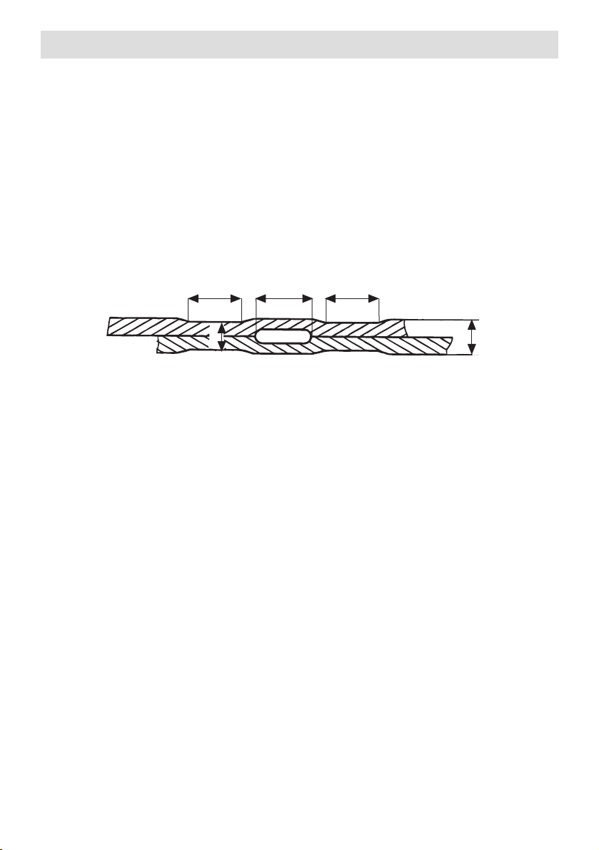
Cross-sectional diagram of an overlap weld
Seam thickness reduction = A – B
A : Thickness of upper and lower
geomembrane liner
B : Thickness of welding seam
C : Width of test channel 15 +/- 2 mm
D : Width of weld ≥ 15 mm
• Welding seam geometry ➝ The proof of quality in a welding seam (peel test,
tensile test) depends upon the thickness reduction in the area of the seam.
With a seam thickness reduction ranging between 0.2 – 0.8 mm, the welding
seam geometry is within the permissable range (DVS 2225 part II, BAM). This
permissable range reflects the optimum interaction of welding parameter
temperature, welding pressure and speed under changing ambient conditions during the welding process.
 Loading...