

Leister TAPEMAT, TAPEMAT Spriegel Operating Instructions Manual
TAPEMAT
Leister Process Technologies
Galileo-Strasse 10
CH-6056 Kaegiswil/Switzerland
Tel. +41 41 662 74 74
Fax +41 41 662 74 16
www.leister.com
sales@leister.com
GB
®
2
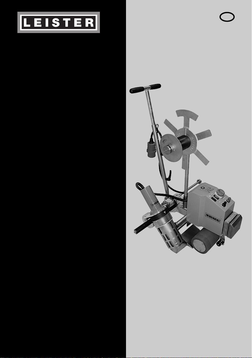
Leister TAPEMAT
Hot-Air welding machine
TAPEMAT: Manually guided automatic hot-air welding machine for welding PVC straps from 45 mm to max.
50 mm wide – as the reinforcement for tarpaulins – on horizontal and level surfaces.
TAPEMAT Spriegel: : Manually guided automatic hot-air welding machine for welding PVC straps (reinforcement
strips) 100 mm and 125 mm wide – as the reinforcement for tarpaulins – on horizontal and level surfaces.
Application
Please read operating instructions carefully before use
and keep for future reference.
Operating Instructions
(Translation of the original operating instructions)
GB
Danger to life if you open the equipment, since this reveals
current-conducting
components and connections.
Remove the mains plug from the plug socket before opening the equipment.
Incorrect use of the hot air tool can present a fire and explosion hazard
especially near combustable materials and explosive gases.
Do not touch the element housing and nozzle when hot as they can cause burns.
Allow the tool to cool down. Do not point the hot air flow at people or animals.
Warning
Connect tool to a receptacle with protective earth terminal. Any interruption of
the protective conductor inside or outside the tool is dangerous!
Use only extension cables/cords with protective conductor!
Conductor cross-section: 4 x 2.5mm
2
The tool must be operated under supervision.
Heat can ignite flammable materials which are not in view.
The machine may only be used by qualified specialists or under their supervision.
Children are not authorized to use this machine.
For personal protection, we strongly recommend the tool be connected to an
RCCB (Residual Current Circuit Breaker) before using it on construction sites.
The mains voltage, that is quoted on the equipment must agree with the mains
voltage.
IEC/EN 61000-3-11; Z
max
= 0.039Ω + j 0.024Ω. If necessary, consultate supply
authority.
You must always use a residual current circuit breaker for protection to
persons when working on building sites.
Protect the tool from damp and wet.
FI
230
400
Caution
The equipment must not be lifted using the additional weight.
3
TAPEMAT TAPEMAT Spriegel
Voltage V~ 3 × 400 3 × 400
Power consumption kW 10 10
Frequency Hz 50 / 60 50 / 60
Temperature °C ca. 650 ca. 650
Speed m/min. 4 – 20 4 – 20
Noise level LpA (dB) 83 83
Weld seam width max. mm 50 2 × 20
Tape width mm 50 100 / 125
Dimensions L×W×Hmm 555 × 435 × 370 555 × 435 × 370
Weight kg 35 40
without power supply cord
Mark of conformity 22
Approval mark 33
Certification scheme CCA CCA
Protection class I 11
Technical data and specifications are subject to change without prior notice.
Leister Process Technologies, Galileo-Strasse 10, CH-6056 Kaegiswil/Switzerland
confirms that this
product,
in the version as brought into circulation through us, fulfils the requirements
of the following EC directives.
Directives
:
98/37, 2004/108, 2006/95
Harmonised standards: E
N 12100-1, EN 12100-2, EN 60204-1, EN 55014-1, EN 55014-2,
EN 61000-6-2, EN 61000-3-2, EN 61000-3-11 (Z
max
),
EN 50366, EN 62233, EN 60335-2-45
Kaegiswil, 25.08.2008
Bruno von Wyl Christiane Leister
Technical Director Owner
Power tools, accessories and packaging should be sorted for environmental-friendly recycling. Only for EC
countries: Do not dispose of power tools into household waste! According to the European Directive
2002/96/ on waste electrical and electronic equipment and its incorporation into national law, power tools
that are no longer suitable for use must be separately collected and sent for recovery in an environmentalfriendly manner.
Disposal
Conformity
Technical data
4
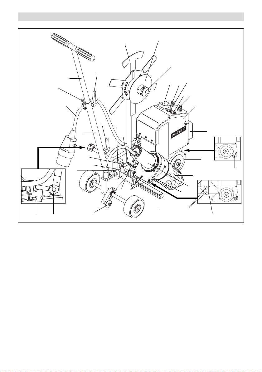
Tool description
1. Mains connection cable
2. Cabinet
3. Main switch
4. Release switch
5. Motor On/Off
6. Speed variation knob
7. Temperature variation knob
8. Welding nozzle
9. Hot air blower
10. Equipment holder
11. Transporting wheel
12. Drive roller / Pressure roller
13. Welding nozzle adjustment screw
14. Welding nozzle adjustment nut
15. Welding nozzle adjustment screws
16. Guiding handle, lower section
17. Guiding handle, upper section
18. Clamping lever, guiding handle joint
19. Clamping lever, height adjustment
20. Retainer (for mains connection cable)
21. Guide roller
22. Additional weight
23. Retaining pin
24. Stop ring
25. Diverting roller
26. Separating wall
27. Strap retaining rollers
28. Sensor
29. Stop screw
30. Contact generator
31. Guide trolley
32. Strap unrolling device
33. Tensioning brake disc
34. Locator (strap unrolling device)
35. Threaded pin
1
2
8
12
27
22
11
3
5
6
7
9
10
13
15
31
30
14
28
16
17
20
18
32
29
34
19
33
21
2423
25
26
4
35
 Loading...