

Leister SEAMTEK 36 Operating Manual
Leister Technologies AG
Operating Manual
Welding Machine SEAMTEK 36
Revision: A
QM
Page
1 / 62
Created
04.04.2014 TEX
Released
Modified
OPERATING MANUAL
Software-Version from V 3
© 2013 Leister Technologies AG, CH-6056 Kaegiswil
Leister Technologies AG, Schwarzenbergstrasse 10, CH-6056 Kaegiswil/Switzerland
Tel. +41 41 662 74 74 Fax +41 41 662 74 16
www.leister.com leister@leister.com
1
Production Code 140528xxxx
SEAMTEK 36

Leister Technologies AG
Operating Manual
Welding Machine SEAMTEK 36
Revision: A
QM
Page
2 / 62
Created
04.04.2014 TEX
Released
Modified
TABLE OF CONTENTS
Abbreviations __________________________________________________________________ 5
Disposal _______________________________________________________________________ 5
1.0 Introduction ______________________________________________________________ 6
1.1 Manual Conventions ________________________________________________________ 6
1.2 Manual Arrangement _______________________________________________________ 8
1.3 The SEAMTEK 36 ___________________________________________________________ 8
1.4 Operating Principle ________________________________________________________ 9
1.5 SP Specifications __________________________________________________________ 10
1.6 Technical Support _________________________________________________________ 10
2.0 Machine Physical Components ______________________________________________ 10
2.1 Base Frame ______________________________________________________________ 10
2.2 Primary Power Panel ______________________________________________________ 10
2.2.1 Graphite Vane Air Pump ____________________________________________________ 11
2.3 Upper Beam Design and Construction ________________________________________ 11
2.3.1 Upper Beam Fasteners ___________________________________________________ 11
2.4 Control Module __________________________________________________________ 11
2.5 Upper Wheel Module ______________________________________________________ 12
2.6 Hot Air Module ___________________________________________________________ 13
2.7 Lower Wheel Modules (LWM) _________________________________________________ 13
2.7.1 Pedestal Lower Wheel Module ____________________________________________ 13
2.7.2 Side Arm Lower Wheel Module ____________________________________________ 15
2.7.3 Quick Arm ________________________________________________________________ 15
2.8 Accessories ________________________________________________________________ 17
2.8.1 Tape Delivery System ___________________________________________________ 17
2.8.2 Wheels and Nozzles ________________________________________________________ 18
2.8.3 Guides ___________________________________________________________________ 18
3.0 Setup and Installation _____________________________________________________ 18
2

Leister Technologies AG
Operating Manual
Welding Machine SEAMTEK 36
Revision: A
QM
Page
3 / 62
Created
04.04.2014 TEX
Released
Modified
3.1 A Word about Physical Environment __________________________________________ 19
3.2 Setup Procedure __________________________________________________________ 19
3.3 Pre-start Checklist ________________________________________________________ 19
3.4 Power and Air Requirements ________________________________________________ 20
3.4.1 Verifying Correct Electrical Power & Connections _____________________________ 20
3.4.2 Connecting Shop Air ____________________________________________________ 20
4.0 Controls: Switches, Foot Pedals and Touch Screen _______________________________ 21
4.1 Description of Control Module Touch Screen & Switches _________________________ 21
4.1.1 Air Cylinder Mode Select Switches ____________________________________________ 26
4.1.2 Wheel Pressure Regulators __________________________________________________ 27
4.2 Emergency Stop Button ____________________________________________________ 28
4.3 Foot Pedal Assembly Description ____________________________________________ 28
4.3.1 Lower Row - Motor and cylinder control ____________________________________ 29
4.3.2 Upper Row - Wheel Speed Corrections______________________________________ 29
5.0 Energizing and De-energizing ________________________________________________ 30
5.1 Energizing _______________________________________________________________ 30
5.2 De-energizing ____________________________________________________________ 31
6.0 Weld Setup __________________________________________________________ 31
6.1 Setting Weld Pressure and Clamp Pressure for the Upper Wheel Module ____________ 32
6.2 Starting the Weld Air Pump _________________________________________________ 32
6.3 Setting Pre-weld Starting Values ______________________________________________ 34
6.3.1 Weld Air Temperature ___________________________________________________ 34
6.3.2 Base Speed ____________________________________________________________ 34
6.3.3 Inputting the settings _______________________________________________________ 34
7.0 Operations ______________________________________________________________ 35
7.1 Placing Fabric in the Weld Head _____________________________________________ 35
7.2 Selecting a Lower Wheel Module (LWM) ______________________________________ 36
7.3 Welding a Test Strip ________________________________________________________ 36
7.4 Welding a Typical Seam ____________________________________________________ 42
7.5 Stopping and Starting on a Seam _____________________________________________ 43
7.6 Using the Foot Pedals ______________________________________________________ 44
3

Leister Technologies AG
Operating Manual
Welding Machine SEAMTEK 36
Revision: A
QM
Page
4 / 62
Created
04.04.2014 TEX
Released
Modified
7.6.1 Upper Left Row—Seam Heat Correction _____________________________________ 44
7.6.2 Upper Left—Hands- Free Freewheel ________________________________________ 44
7.6.3 Upper- Right—Fabric Registration Error Correction ____________________________ 45
7.7 Calibration ______________________________________________________________ 45
7.8 Top Wheel Differential % _____________________________________________________ 46
8.0 Basic Hot Air Welding ______________________________________________________ 47
8.1 Allow Smooth, Drag-Free Fabric Flow _________________________________________ 47
8.2 Use a Lower Wheel Speed When Necessary ____________________________________ 47
8.3 Run the Seam Cold ________________________________________________________ 47
8.4 Be Ready to Stop _________________________________________________________ 48
8.5 Relax and Take Your Time __________________________________________________ 48
9.0 Changing Over Modular Features ____________________________________________ 48
9.1 Reconfiguring Lower Wheel Modules _________________________________________ 48
9.1.1 Pedestal _________________________________________________________________ 49
9.1.2 Side Arm _________________________________________________________________ 50
9.1.3 Quick Arm ________________________________________________________________ 51
9.2 Changing Wheel Assemblies ________________________________________________ 52
9.2.1 Upper Wheel Module, Wheel Assembly Removal and Change Over _________________ 53
The following sequence of pictures will assist you in changing the wheel for the Upper Wheel Module. _ 53
9.2.2 Pedestal, Wheel Assembly Removal and Change Over ____________________________ 54
9.2.3 Side-arm, Wheel Assembly Removal and Change Over ____________________________ 57
9.2.4 Quick Arm, Wheel Assembly Removal and Change Over ___________________________ 57
9.3 Changing Nozzles ____________________________________________________________ 59
9.3.1 Adjusting Nozzle Position ___________________________________________________ 60
9.4 Tape Delivery System Installation ______________________________________________ 60
4
Leister Technologies AG
Operating Manual
Welding Machine SEAMTEK 36
Revision: A
QM
Page
5 / 62
Created
04.04.2014 TEX
Released
Modified
Power tools, accessories and packaging should be sorted for environmentalfriendly recycling. Only for EC countries: Do not dispose of power tools into
household waste! According to the European Directive 2002/96 on waste
electrical and electronic equipment and its incorporation into national law,
power tools that are no longer suitable for use must be separately collected
and sent for recovery in an environmental-friendly manner.
(Translation of the original operating instructions)
Abbreviations
AHAM Articulating Hot Air Module
LWM Lower Wheel Module
QA Quick Arm
SA Side Arm
TDS Tape Delivery System
UWM Upper Wheel Module
Disposal
5
Leister Technologies AG
Operating Manual
Welding Machine SEAMTEK 36
Revision: A
QM
Page
6 / 62
Created
04.04.2014 TEX
Released
Modified
1.0 Introduction
This document describes the assembly and operation of the SEAMTEK 36 manufactured by
Leister Technologies AG of Kägiswil, Switzerland. This includes setup and installation, operating
procedures, and a description and purpose of each of the various modules available for use
with your SEAMTEK 36. A troubleshooting checklist, warranty information, and an index are
also included in this documentation. This manual is designed to ensure proper setup,
installation, and operation of the SEAMTEK 36 with a minimum of effort. Please read through
all sections of this document before using your SEAMTEK 36.
This version supersedes any previously dated version and is superseded by any later dated
version.
Leister Technologies AG believes the information in this manual to be complete and accurate,
but makes no warranty, either actual or implied, as to the completeness and accuracy of this
information, and assumes no liability for the use of this information.
This manual may be updated from time to time and without notice. The latest published
versions of all Leister Technologies AG users' manuals are available to authorized users by
contacting Leister Technologies AG.
1.1 Manual Conventions
Various text conventions are used throughout this documentation. In addition to providing
readability, these formatting styles are designed so that you will readily know references to a
particular button, for instance, from a discussion of that button's features.
These conventions are as follows:
All labels are written as they appear on the machine.
Note: Notes like this one are used to provide supplemental information.
The following symbols and notations provide additional cautionary information:
Warning: These messages warn against possible dangers that may occur as the result of unsafe
operating practices.
6
Leister Technologies AG
Operating Manual
Welding Machine SEAMTEK 36
Revision: A
QM
Page
7 / 62
Created
04.04.2014 TEX
Released
Modified
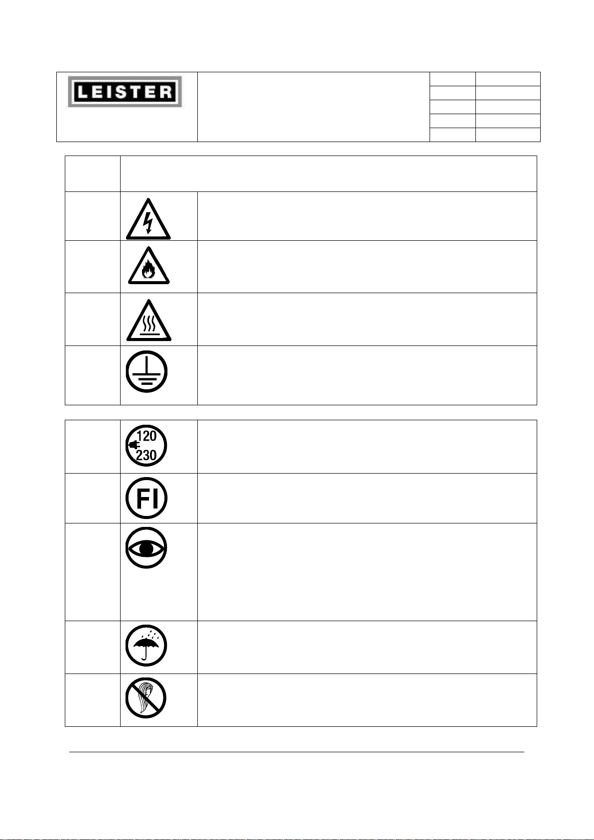
Warning:
Symbols, like this one, alert you to practices that may cause damage to the machine.
Opening the device is extremely dangerous, since live parts and
connections are exposed. Remove the plug from the socket before
opening the device.
Danger of fire and explosion if the extrusion welder is used
incorrectly (e.g. overheating of material), particularly near
combustible materials and explosive gases.
Danger – can cause burns ! Do not touch bare metal parts and
emerging material while hot. Allow the device to cool. Do not direct
stream of hot air or emerging material towards people or animals.
Connect device to power socket with protective earth conductor.
Any break in the protective earth conductor inside or outside the
device is dangerous!
Only use extension cables with a protective earth conductor!
Caution:
The nominal voltage indicated on the device must correspond to the
mains voltage. If power failure occurs, the main switch and drive
must be switched off (release locking device).
When using the device on building sites, a residual current circuit
breaker is essential for the safety of persons there.
The device must not be left unattended when in use. Heat can reach
combustible materials which are out of sight.
The device may only be used by trained personnel or under their
supervision. Children may not use the device under any
circumstances.
Keep away from wet and damp areas.
While working on the open system avoid wearing garments such as
shawls, scarves and ties. Long hair must be tied or protected by
headgear.
7

Leister Technologies AG
Operating Manual
Welding Machine SEAMTEK 36
Revision: A
QM
Page
8 / 62
Created
04.04.2014 TEX
Released
Modified
1.2 Manual Arrangement
This manual is divided into ten distinct sections:
1. Introduction
2. Setup and Installation
3. Modular and Adjustable Features
4. Operator Controls / Interface
5. Energizing / De-energizing
6. Weld Set-up
7. Operations
8. Basic Hot Air Welding
9. Change Over and Adjusting Modular Features
10. Index
1.3 The SEAMTEK 36
Thank you for purchasing the world's finest rotary hot air welder. The SEAMTEK 36 is a
computer-controlled hot air welder used for sealing industrial coated fabrics such as
polyvinylchloride (PVC), polyurethane (PU), polyethylene (PE), and polypropylene (PP), which are
used today for a vast array of important and interesting products. These include tents, awnings,
tarpaulins, inflatable boats, water toys, geo-membranes, truck covers, farm building covers,
fishing waders, environmental and protective garments, lighter than air craft, and many other
applications. The possibilities are virtually limitless.
8
Leister Technologies AG
Operating Manual
Welding Machine SEAMTEK 36
Revision: A
QM
Page
9 / 62
Created
04.04.2014 TEX
Released
Modified
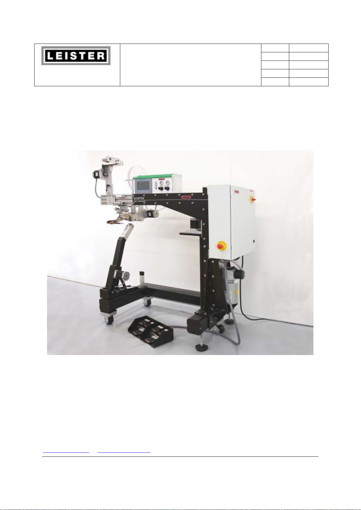
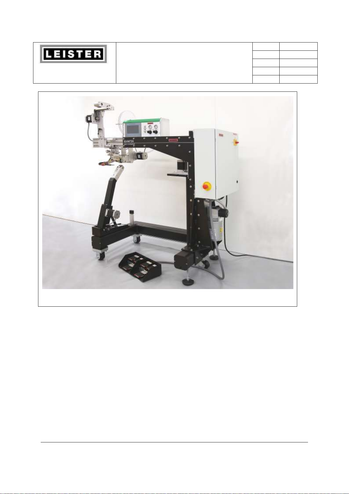
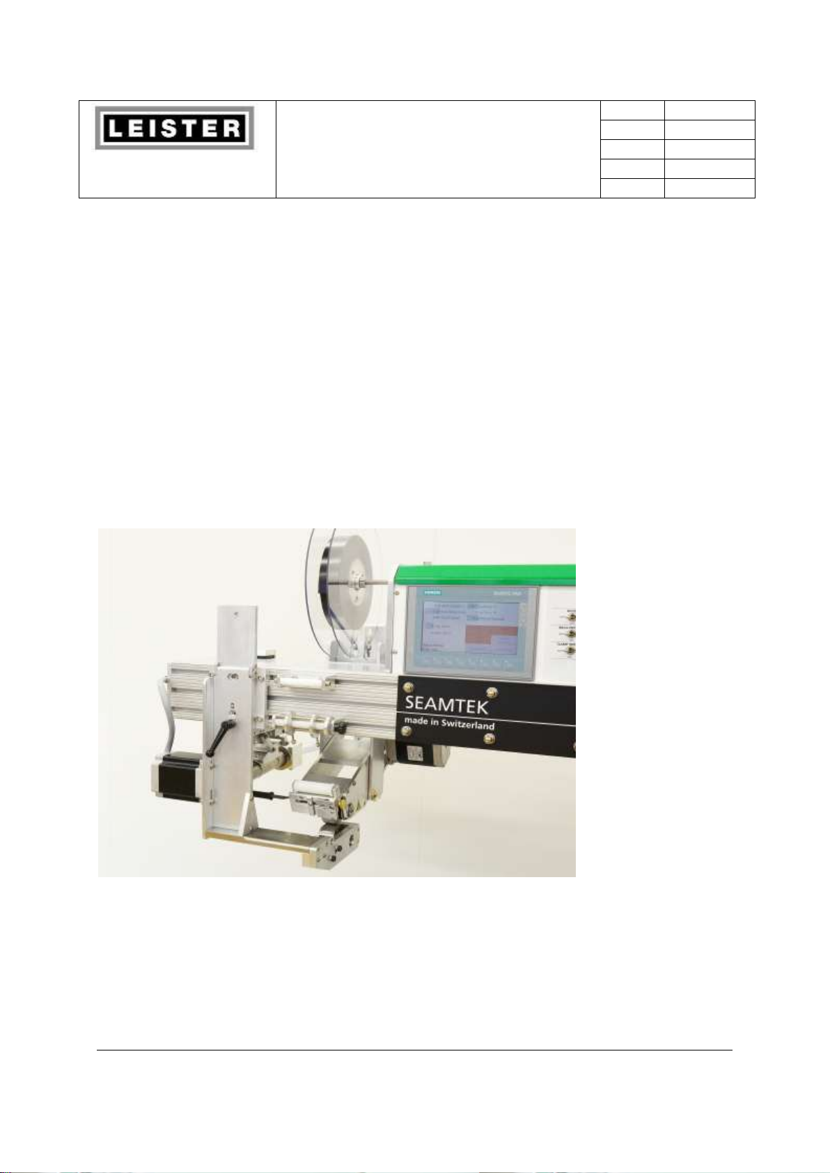
Figure 1 Front View of the SEAMTEK 36
Rotary hot air welding is a controlled and constant flowing process with speeds ranging from
.8 – 72 feet per minute (0.25 – 22 meters per minute), accommodating long fast seams or
slow intricate seams. Unlike dialectic welders which have been in use now for about 40
years, the SEAMTEK 36 can produce a wide variety of three-dimensional products. The
SEAMTEK 36 is fully shielded from RF radiation and works well as a compliment to RF
welding.
1.4 Operating Principle
In operation, the SEAMTEK 36 directs a stream of hot air (from 200 to 1300 ° F, 35°C - 700°C)
onto the joining surfaces of the coated fabric pattern pieces, which then roll between two drive
wheels where pressure is applied and the seam is welded.
9

Leister Technologies AG
Operating Manual
Welding Machine SEAMTEK 36
Revision: A
QM
Page
10 / 62
Created
04.04.2014 TEX
Released
Modified
1.5 SP Specifications
Utility Requirements
Air: 100-120 psi @1 cfm
Power: 230V~ to 240 V~, 50/60 Hz, single phase, 17 amps
Weight: 330k
The SEAMTEK 36 is a very precise machine in that it can maintain an air stream weld
temperature within +/-2 degrees F (°C) and can maintain the speed of each drive wheel
independently within +/- .01 inch per second at weld speeds ranging from 0.8 to 72’/min (0.25
– 22 meters per minute). This precision insures high quality welds over a very broad range of
fabric types, welding speeds, and temperatures. The SEAMTEK 36 is a highly versatile machine
and works well in conjunction with other welding formats such as Radio Frequency (RF).
1.6 Technical Support
This manual is designed to serve as a complete, easy-to-use reference source for the SEAMTEK
36. If any questions concerning the use and/or maintenance of your SEAMTEK 36 cannot be
answered by this documentation, please contact Leister Technologies AG for further support.
Phone +41 41 662 74 74
Fax +41 41 662 74 16
E-mail Leisterinfodesk@leister.com
2.0 Machine Physical Components
This section describes the various modules available for use with your SEAMTEK 36. Contact
Leister Technologies AG for further information on ordering optional modules.
The SEAMTEK 36 is a modular system. This allows several components to be field replaced in
minutes with no special tools required. It also allows the machine to be configured in several
different ways.
2.1 Base Frame
The base frame in constructed of steel, making it extremely strong stable platform.
2.2 Primary Power Panel
The Primary Power Panel is a metal NEMA box that is mounted to the vertical post of the
machine. This module houses the primary power management system and control computer
10
Leister Technologies AG
Operating Manual
Welding Machine SEAMTEK 36
Revision: A
QM
Page
11 / 62
Created
04.04.2014 TEX
Released
Modified
Caution: Pressing The Emergency Stop button will shut off the machine
entirely without allowing the heating element to complete its automatic 3minute cool down cycle. This could cause the heater element to be
destroyed or severely shorten its life expectancy. Only use the E-Stop for
emergency purposes
!
and all motor drives. Also located on the door the primary power panel is the service
disconnect breaker, which is used to energize and de-energize the SEAMTEK 36. On the
operator side of the Primary Power Panel is an Emergency Stop button. Pushing this button will
instantly shut off all power and release all compressed air form the machine.
2.2.1 Graphite Vane Air Pump
Directly beneath the Primary Power Panel is the graphite vane air pump. The pump delivers a
constant volume and pressure of airflow to a AHAM and finally to the welding nozzle. This
pump is designed to operate for thousands of hours, delivering a steady stream of clean air
with a minor amount of maintenance. This pump eliminates the need for large in house air
compressors and the expensive drying systems needed to clean that air. Only a small air
compressor is needed to operate the SEAMTEK 36 pneumatic air cylinders. When the SEAMTEK
36 is to be shut down for the day the pump will complete a 3-minute cool down cycle to cool
the heater element. This will help extend the life of the heater elements.
2.3 Upper Beam Design and Construction
The upper beam assembly is constructed from high strength, lightweight, slotted, aluminum
extrusion. This design allows easy side-to-side adjustment of the position of the various
modules that attach to the upper beam.
2.3.1 Upper Beam Fasteners
The surfaces of the upper beam extrusion are not flat; instead, they are slightly recessed next to
the slots. In this way, when a flat object is bolted to the extrusion face, the extrusion acts as a
spring acting against the threads of the nut and bolt. This means that a very secure joint can be
achieved with a minimal tightening of the nut—typically 1/2 to 3/4 turns after finger tight is
adequate.
2.4 Control Module
Mounted in the beam is the control module. It houses the touch screen operator interface. This
is a flat panel display screen that shows the majority of the machines controls and feedback
information. The screen is pressure sensitive. To make adjustments to the welding process the
operator actually touches the images of buttons on the screen itself. The screen may change
11
Leister Technologies AG
Operating Manual
Welding Machine SEAMTEK 36
Revision: A
QM
Page
12 / 62
Created
04.04.2014 TEX
Released
Modified
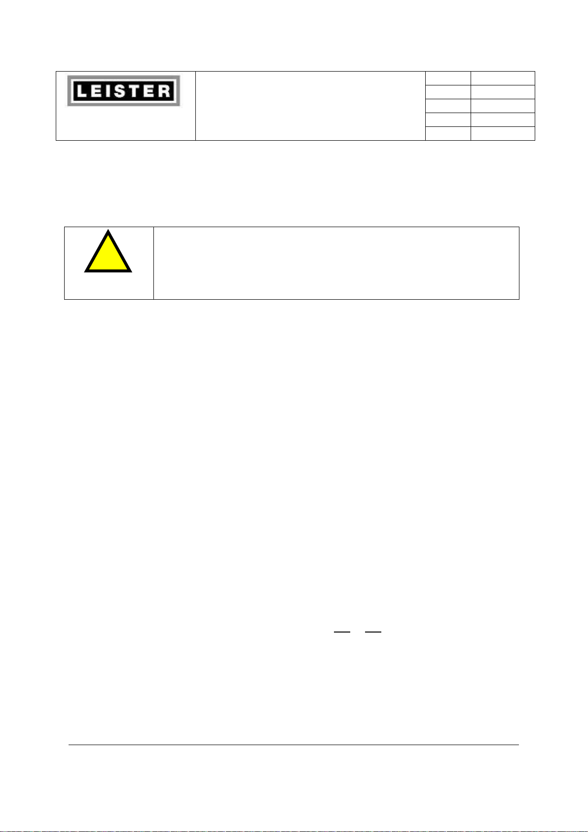
Caution: the operators’ fingers should only touch the touch screen. Sharp
objects such as pencils and long fingernails can damage the touch screen.
This type of damage is not covered by the machine warranty
!
depending upon what “button” is pushed. This is the control for adjusting temperature, speed,
and other operation parameters.
Figure 2 Touch Screen
2.5 Upper Wheel Module
Essential to the wheel head assembly is the Upper Wheel Module (UWM). The UWM is
mounted on the upper beam. In operation, the upper wheel is lowered onto the lower wheel
module. Next, the hot air weld nozzle travels into position, where it directs a stream of hot air
between the upper and lower drive wheels. The wheels rotate independently under precise,
computer control to pull the heated fabric through the weld head apply weld pressure along
the seam. The UWM raises and lowers in a lever action. This allows the upper wheel to climb
over thick seams junctions easier than other rotary welders that utilize a vertical air cylinder
with the upper wheel connected to the end of it.
12

Leister Technologies AG
Operating Manual
Welding Machine SEAMTEK 36
Revision: A
QM
Page
13 / 62
Created
04.04.2014 TEX
Released
Modified
2.6 Hot Air Module
The Articulating Hot Air Module (AHAM) uses a 3600 watt heating element to superheat
weld air. Heated air is then delivered to the weld point through the weld nozzle, which slides
in and out of weld position. A pair of air cylinders that connect to your shop’s pneumatic air
source provides the movement of the weld nozzle. In its rest position the AHAM sits to the
left of the UWM and above about 2” (50mm). This position keeps the hot nozzle far enough
away from the operators hands so they can position fabric between the weld wheels without
getting burnt. When activated the AHAM drops the nozzle down to the proper height and
then slides it to the right placing the nozzle in the proper position to deliver the hot air to the
seam. The weld nozzle is adjustable on four different axes—side/side; up/down plus the
nozzle can rotate to direct the air more to the top or bottom wheel for special applications.
The weld air runs through the triple pass heater tube, preheating the air before it enters the
heater element. This helps lengthen the element life. The thermocouple is located close to
the nozzle to give accurate air temperature readings.
2.7 Lower Wheel Modules (LWM)
There are 3 different lower wheel modules (LWM) that can be installed on any SEAMTEK 36 hot
air welder. These are the Pedestal, Side Arm and Quick Arm. A SEAMTEK 36 can have just one
or all 3 making the SEAMTEK 36 highly versatile. Each of these LWMs are independently driven
by their own computer controlled stepper motors. In the next few sections these LWMs are
explained. All 3 LWM can be quickly put into the operating position while the others are
stowed. These changes take just a few seconds.
2.7.1 Pedestal Lower Wheel Module
The Pedestal LWM is the most widely used of all the LWM. It can be used for making several
different seam types such as overlaps, butt joints, hems and many more. Like all of the
LWMs, the Pedestal can support wheel widths ranging from ¼” to 2.5” (8mm to 63.5mm).
However, it requires the use of 2 separate “heads” to achieve this complete range (a narrow
or a wide head). The wheels can be made of stainless steel or Shore A Duro40 or Duro70
silicone. The Pedestal can be used to make long straight seams, curves, and several 3
dimensional seams. It is also used heavily for seam sealing sewn seams with heat activated
adhesive tapes.
13
Leister Technologies AG
Operating Manual
Welding Machine SEAMTEK 36
Revision: A
QM
Page
14 / 62
Created
04.04.2014 TEX
Released
Modified
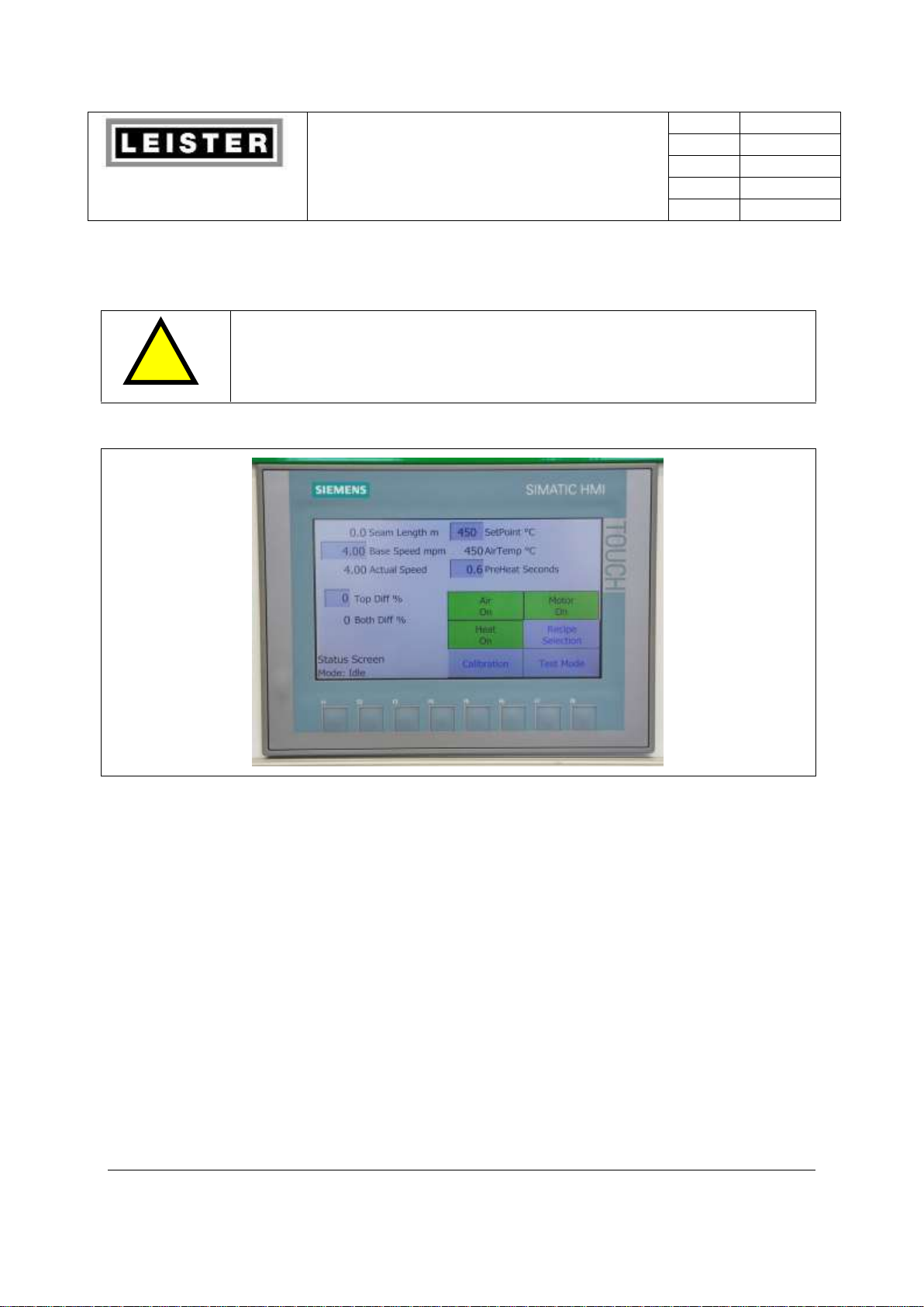
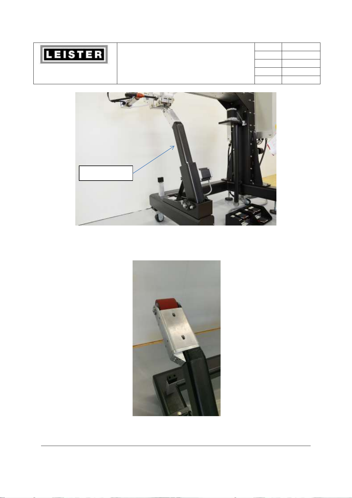
Pedestal
Figure 3 Pedestal Ready to use
Figure 4 Pedestal with the wide head
14
Leister Technologies AG
Operating Manual
Welding Machine SEAMTEK 36
Revision: A
QM
Page
15 / 62
Created
04.04.2014 TEX
Released
Modified
Side arm
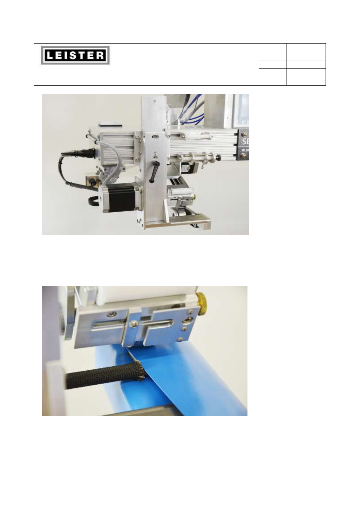
2.7.2 Side Arm Lower Wheel Module
The Side Arm lower wheel module provides the ability to weld tubular items to other fabric
pieces. Like all lower wheel modules the Side Arm accepts various size steel wheels. Its own
stepper motor with a series of belts and gears drives the side arm. This module locks into
welding position with 5/16-18 kip handle, and conveniently folds down and out of the way of
the weld head area when not in use. The Side Arm is excellent for operations such as taping
gloves to sleeves on protective suits, booties to legs and filters.
Figure 5 Front view of side arm lower wheel
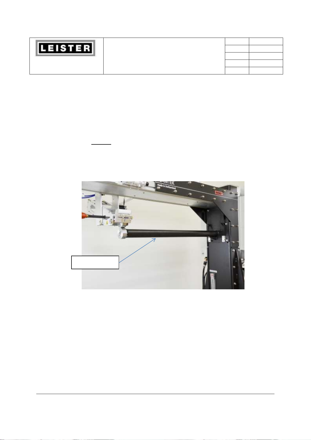
2.7.3 Quick Arm
The Quick Arm is a LWM designed to make long continuous tubes. It connects to the upper
beam via a quick release bracket. The Quick Arm can support the full range of wheels. The
Quick Arm can also produce standard overlap seams to connect flat panels like the Pedestal.
This LWM is great for making dry bags, inflatable boats, ventilation tubes and many other
products.
15
Leister Technologies AG
Operating Manual
Welding Machine SEAMTEK 36
Revision: A
QM
Page
16 / 62
Created
04.04.2014 TEX
Released
Modified
Figure 6 Quick Arm LWM.
Off to the right you can see the Side Arm in its stowed position.
Figure 7 A tube being formed on the Quick Arm
16
Leister Technologies AG
Operating Manual
Welding Machine SEAMTEK 36
Revision: A
QM
Page
17 / 62
Created
04.04.2014 TEX
Released
Modified
Tape spool reel
Adjustable tape
Guide
2.8 Accessories
The SEAMTEK 36 is capable of utilizing other attachments and accessories to make it even
more flexible take a look at the following for more information.
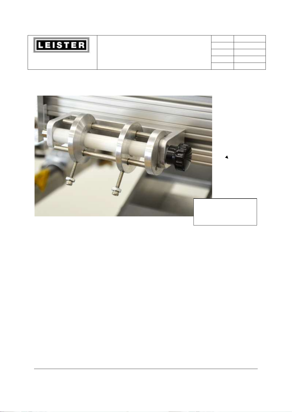
2.8.1 Tape Delivery System
The optional Tape Delivery System (TDS) module is designed to supply a steady stream of
coated fabric tape or heat activated adhesive seam tape to the weld head area. Among other
applications, the TDS delivers adhesive material that can be used to seal perforated seams. A
tower-mounted tape reel attaches to the top of the upper wheel module. Tape stored on the
reel is delivered to a tension control device. It then passes through a guide that can
accommodate various tape widths and to the weld head area where heat and pressure are
applied.
Figure 8 Tape Delivery System (TDS) Tension control device not shown
17
Leister Technologies AG
Operating Manual
Welding Machine SEAMTEK 36
Revision: A
QM
Page
18 / 62
Created
04.04.2014 TEX
Released
Modified
Thumbscrew
adjustment for tape
Figure 9 Adjustable Tape Guide
2.8.2 Wheels and Nozzles
The SEAMTEK 36 creates various seam widths and types using the wide variety of quickchange wheels and nozzles. Take a look at the options below.
Steel Wheels 0.250” – 2.5” wide (8mm to 63.5mm)
Silicone wheels 0.50”- 2.5” wide (8mm to 63.5mm)
Custom wheels can be manufactured upon request (grooved, stepped)
2.8.3 Guides
Various guides can be used with the SEAMTEK 36. Either standard sewing machine guide or
custom guides can be made to suit your needs.
3.0 Setup and Installation
This section provides setup and installation information for your SEAMTEK 36. Before applying
power, read through all applicable sections of this document.
18

Leister Technologies AG
Operating Manual
Welding Machine SEAMTEK 36
Revision: A
QM
Page
19 / 62
Created
04.04.2014 TEX
Released
Modified
3.1 A Word about Physical Environment
The machine should be uncrated and installed as soon as possible but if it is stored, it should be
stored in an area that is dry and the temperature is maintained from 5 to 55 C.
When selecting a site for the SEAMTEK 36 the area it should meet the following criteria:
An area that is dry, dust free and has good ventilation.
An ambient temperature range of 42°F – 104°F (5 to 40 C).
On a floor that is flat, solid and level.
An area that is free from large amounts of vibration or shock caused by other machines,
vehicle traffic, etc. that may damage the machine. Evaluate the area for vibration or
potential for shock; if any exists provide appropriate isolation.
3.2 Setup Procedure
The SEAMTEK 36 is easy to set up. You should have a forklift on hand to off-load the crated
machine from the shipper. When you have decided on a working location for your SEAMTEK 36,
follow these steps:
1. Remove the crate.
2. Remove the internal straps that secure the machine to the skid.
3. Lift the machine off the shipping skid
4. Raise the leveling pads on the bottom of the frame. This allows the machine to be easily
wheeled to a convenient location.
5. Once the machine is in position lower the leveling pads to level the machine. This is
accomplished by using a carpenters level and the adjustable leveling pads provided. This
also cocks welder in place.
6. Add wheels if they were removed for shipment.
3.3 Pre-start Checklist
Before you start the SEAMTEK 36, you should always take time to perform a ‘pre-start’ check by
completing the following:
Caution: To avoid damaging the machine, be certain that electrical power and shop air are
disconnected before performing any of the following steps.
19
 Loading...