

Page 1
1
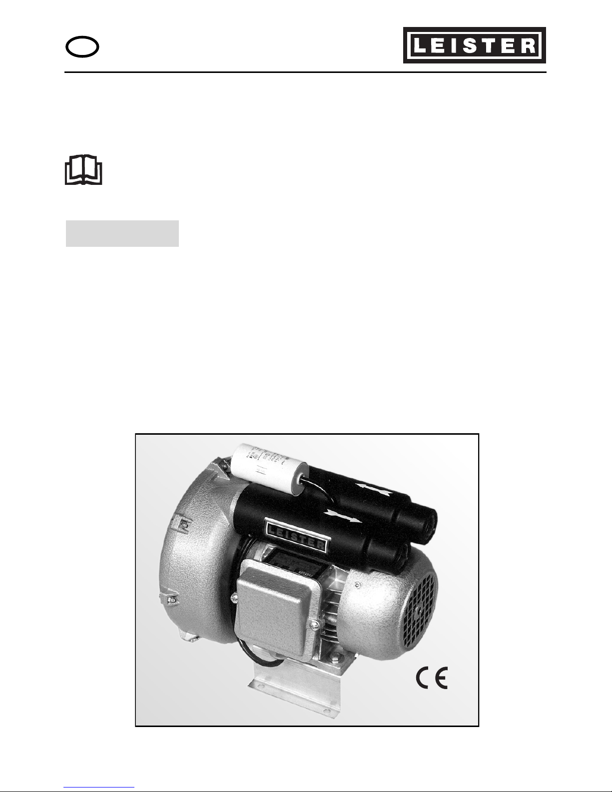
LEISTER ROBUST
High Pressure Blower
Please read operating instructions carefully before use
and keep for further reference.
GB
OPERATING INSTRUCTIONS
• The LEISTER Blower Robust is suitable for building into machines, installations
and appliances and is designed for continuous operation.
• It is suitable for delivering air, non combustible, non corrosive and non
explosive gases.
• Air supply for LEISTER Hot Air tools, for intake air supply and for cooling.
• Ventilation of tanks, aquariums and different applications for textile ma-
chines.
• Drawing off of welding gases and fumes.
• Transfer of granular and loose materials.
• Vacuuming screen printing machines and air tables.
APPLICATION
®
LEISTER Process Technologies, Riedstrasse, CH-6060 Sarnen/Switzerland
Tel. +41- 41 662 74 74 Fax +41- 41 662 74 16
www.leister.com [email protected]
Page 2
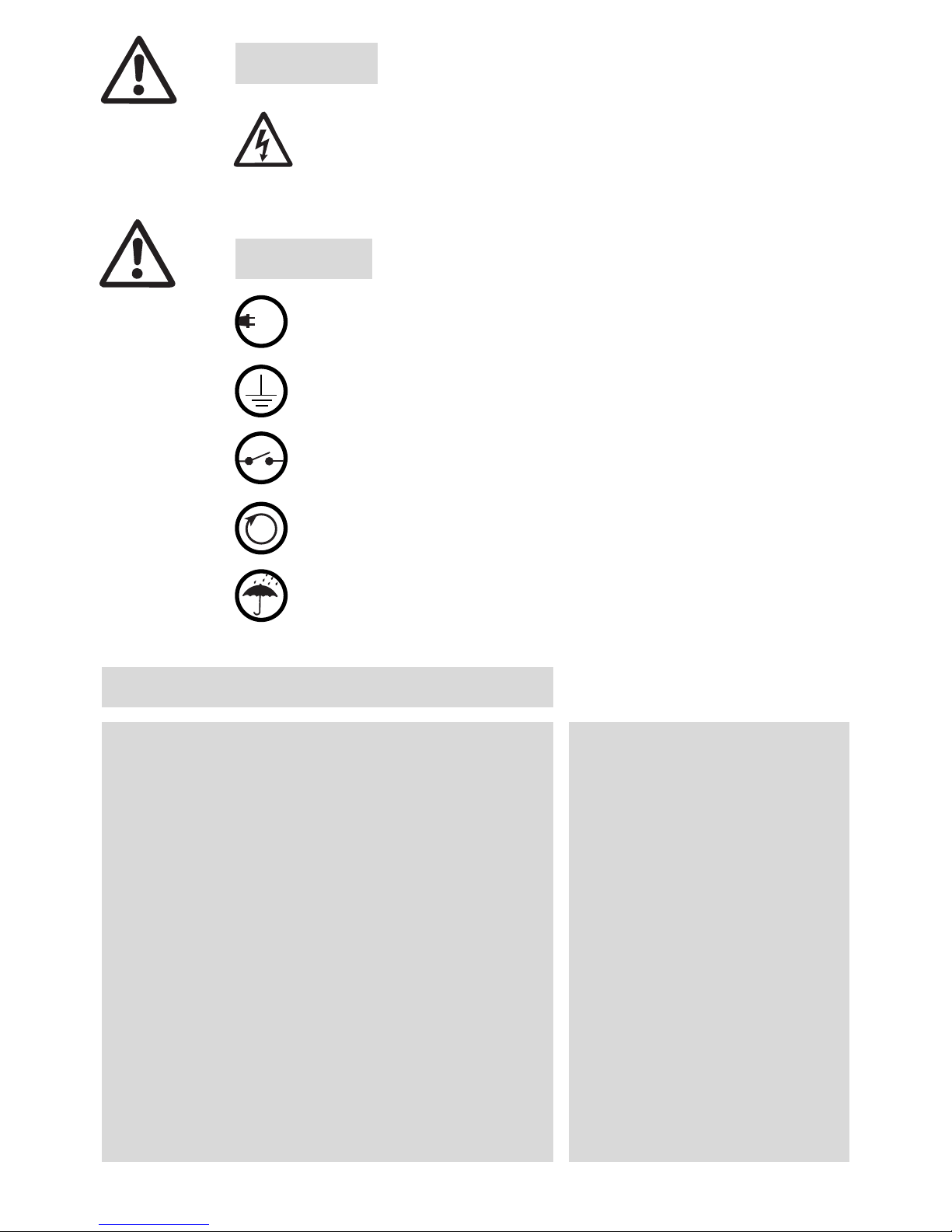
Danger! When opening up the tool live connections
are exposed. Therefore, before opening it, disconnect all poles from the mains.
The tool must be grounded with the protective conductor.
The voltage rating stated on the tool should correspond to the mains voltage.
Protect tool from damp and wet.
Use thermal overload protection switch.
Pay attention to the direction of rotation.
230
400
Design
Voltage for three-phase supply V~
Voltage for single phase supply V~
Condensor for single phase mF
Capacity W
Frequency Hz
Air flow l/min.
Static pressure Pa
Noise level dB (A)
Environmental protection DIN 40050
Diameter of air intake (internal Ø) mm
Diameter of air outlet (internal Ø) mm
Ambient temperature °C
Weight kg
Size (L x B x H) mm
lateral channel compressor
3x230–254 3x380–440
1 x 230 – 254
12
250
50 / 60
1200 / 1300
8000 / 10500
62
IP 54
Ø38
Ø38
<60
8,0
255x221x221
2
WARNING
CAUTION
TECHNICAL DATA
100 Pa = 1 mbar
Page 3
Installation
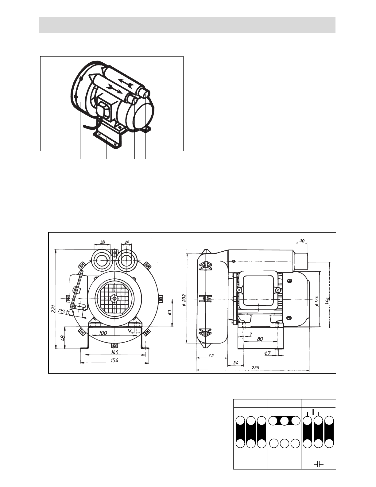
• The tool should be fixed by using four M6 screws on the installation stand (6).
• Protect the tool from vibration and shock.
• The tool can be installed horizontally or vertically.
• Installation dimensions in mm
Operation
• The blower should only take in air at < 60°C.
• For use in a dusty environment, a LEISTER stainless
steel filter should be fitted onto the blower air
intake (2).
• The appropriate connections should be made in
the connection box (4) depending on the voltage.
• The blower should be connected by an electric
engineer. Pay attention to the direction of rotation!
Description of tool
1. Air outlet Ø 38
2. Air intake Ø 38
3. Motor
4. Connection box
5. Connection box lid
6. Installation stand
7. Fan housing
574
6
132
3
USAGE LEISTER ROBUST High Pressure Blower
L1 L2 L3
∆
L1 L2 L3
Y
230– 254 V
380– 440 V 230 – 254 V
W2U1U2V1V2
W1
U1
V1 W1
W2
U1
W2 U2
V2
U2V1V2
W1
Circuit diagram in
connection box lid (5)
L1 N
Page 4

4
BA Robust / 06.2001/GB
• Only LEISTER accessories must be used.
• Repairs should only be carried out by authorized LEISTER Service Centres.
They guarantee a specialised and reliable Repair Service within 24 hours
using original spare parts in accordance with the circuit diagram and spare
parts list.
• Guarantee and liability are in accordance with the guarantee certificate as
well as with the currently valid general business and sales conditions.
• LEISTER Process Technologies rejects any guarantee claims for tools which are
not in their original condition. The tools must never be altered or changed.
Technical data and specifications are subject to change without prior notice.
Your authorized Service Centre is:
WARRANTY AND LIABILITY
SERVICE AND REPAIR
ACCESSORIES
®
LEISTER Process Technologies, Riedstrasse, CH-6060 Sarnen/Switzerland
Tel. +41- 41 662 74 74 Fax +41- 41 662 74 16
www.leister.com [email protected]
 Loading...