

Leister LHS 15, LHS 21 S, LHS 41 L, LHS 61 S, LHS 61 L Operating Instructions Manual
...
LHS
Air Heaters
, 04073,
, 17
: (044)-494-15-97
www.leister.com.ua
leister@leister.com.ua
®

RUS
CN
J
CZ
TR
E
P
SF
S
F
I
2
D
GB
Size 3, 4, 5, 6
Wiring Diagram 7, 8, 9, 10, 11, 12
interface 13
Deutsch Bedienungsanleitung 14
English Operating Instructions 22
Italiano Istruzioni d’uso 30
Français Instructions d’utilisation 38
Espanõl Instrucciones de funcionamiento 46
Português
Manual de instruções 54
Suomi
Käyttöohje
62
Svenska
Bruksanvisning
70
Türkçe Kullanım kılavuzu 78
Česky Návod k obsluze 86
Русский Инструкция по эксплуатации 94
中文 使用手册 102
⽇本語 取扱説明書 110
3
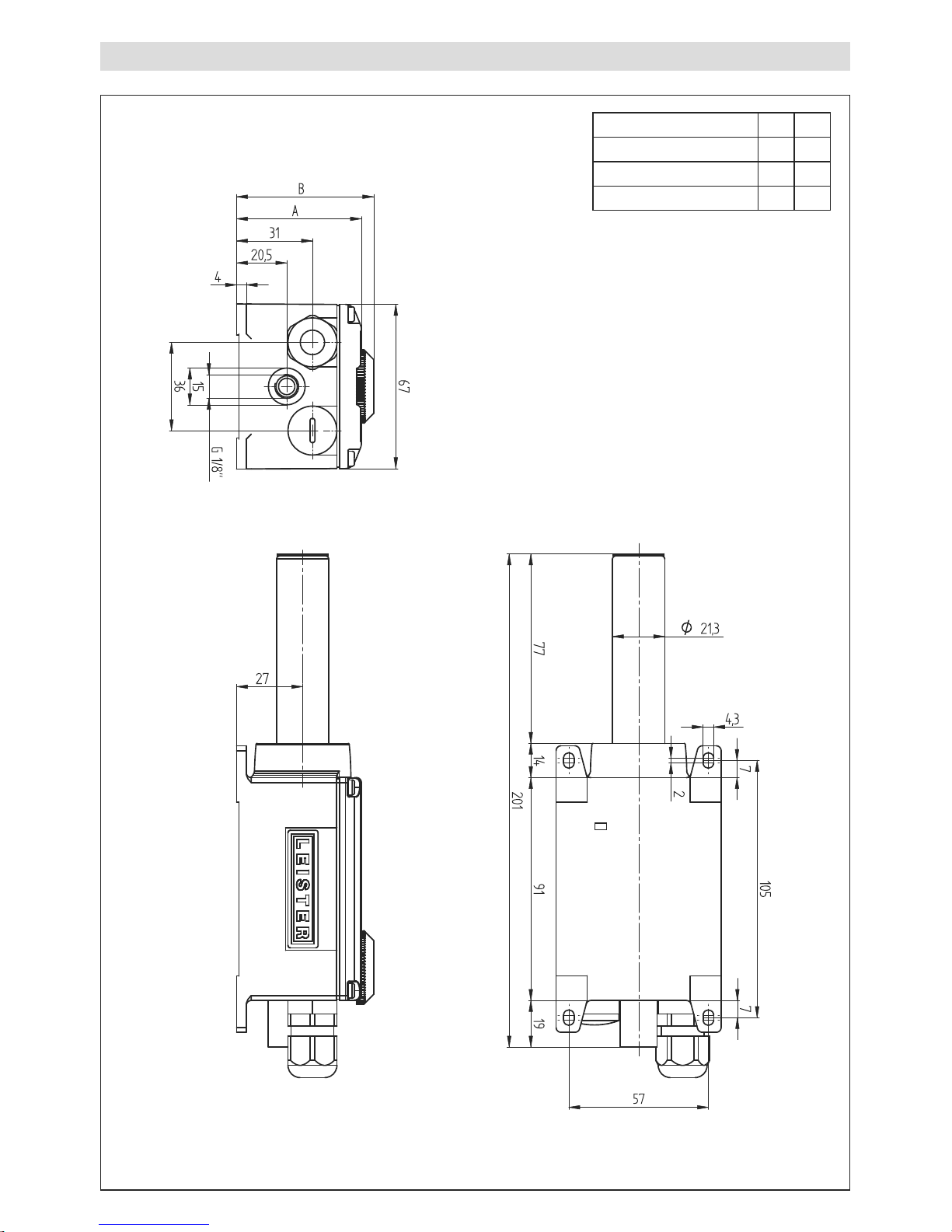
LHS 15 Size mm
Typ A B
LHS 15 CLASSIC
51 51
LHS 15 PREMIUM
51 56
LHS 15 SYSTEM
51 56
4
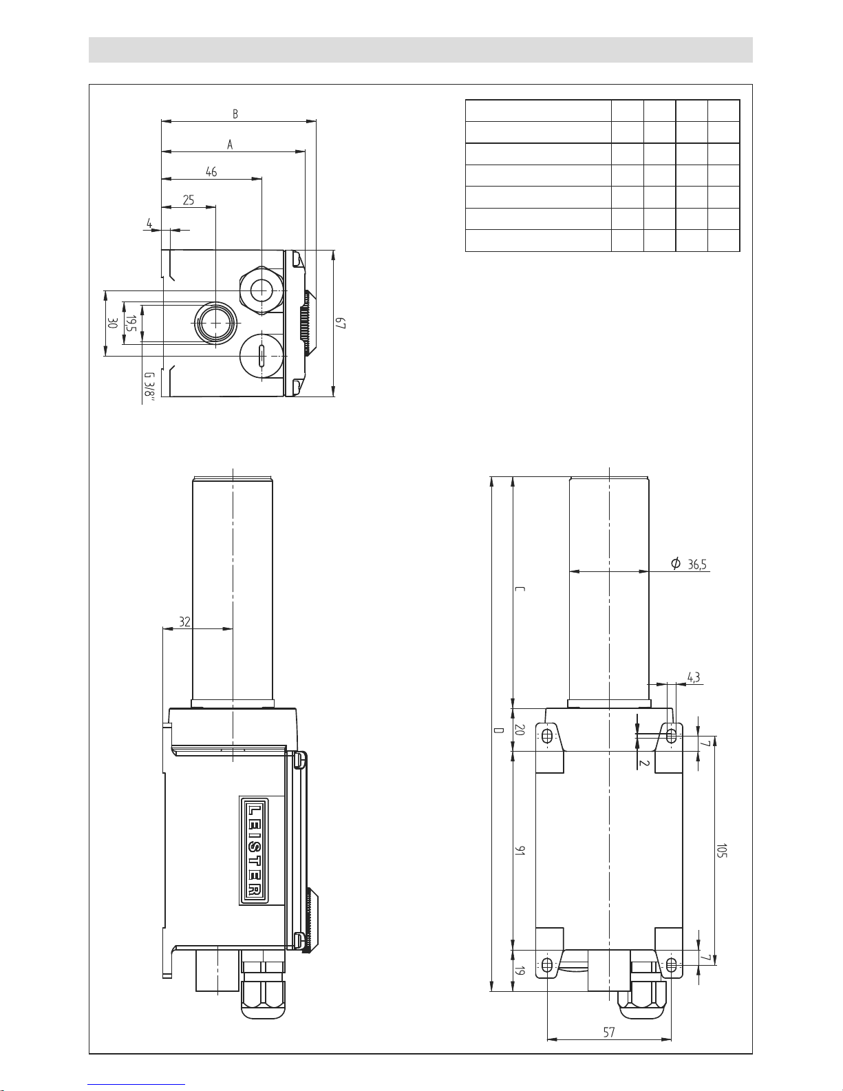
LHS 21 S, LHS 21 L Size mm
Typ A B C D
LHS 21 S CLASSIC
66 66 106 236
LHS 21 L CLASSIC
66 66 136 266
LHS 21 S PREMIUM
66 71 106 236
LHS 21 L PREMIUM
66 71 136 266
LHS 21 S SYSTEM
66 71 106 236
LHS 21 L SYSTEM
66 71 136 266
5
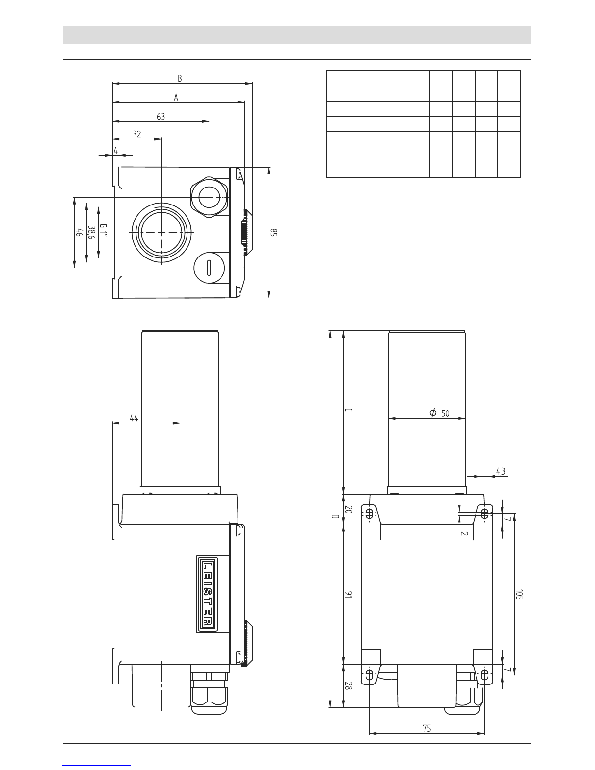
LHS 41 S, LHS 41 L Size mm
Typ A B C D
LHS 41 S CLASSIC
86 86 106 245
LHS 41 L CLASSIC
86 86 136 275
LHS 41 S PREMIUM
86 91 106 245
LHS 41 L PREMIUM
86 91 136 275
LHS 41 S SYSTEM
86 91 106 245
LHS 41 L SYSTEM
86 91 136 275
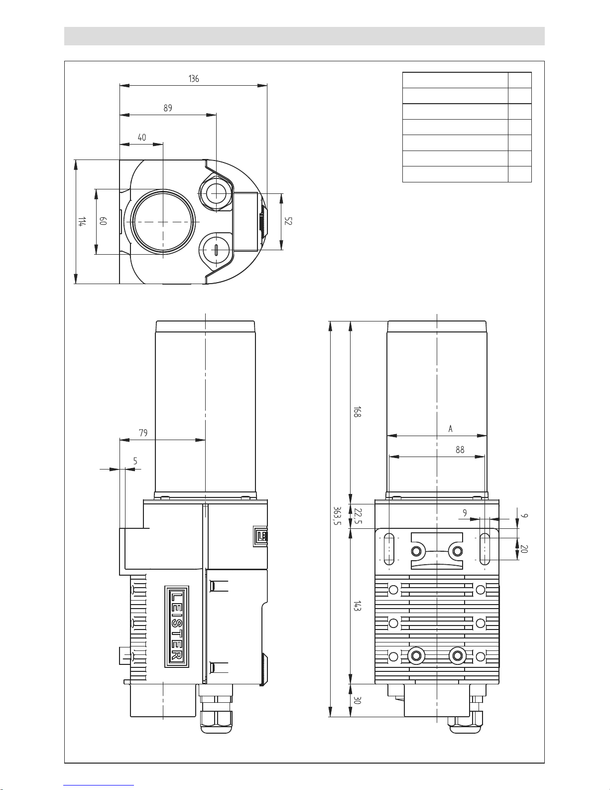
6
LHS 61 S, LHS 61 L Size mm
Typ A
LHS 61 S CLASSIC
ø 62
LHS 61 L CLASSIC
ø 92
LHS 61 S PREMIUM
ø 62
LHS 61 L PREMIUM
ø 92
LHS 61 S SYSTEM
ø 62
LHS 61 L SYSTEM
ø 92
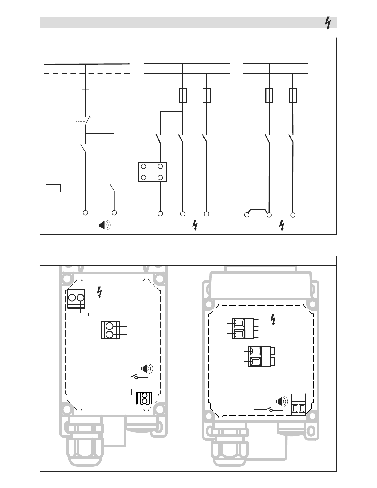
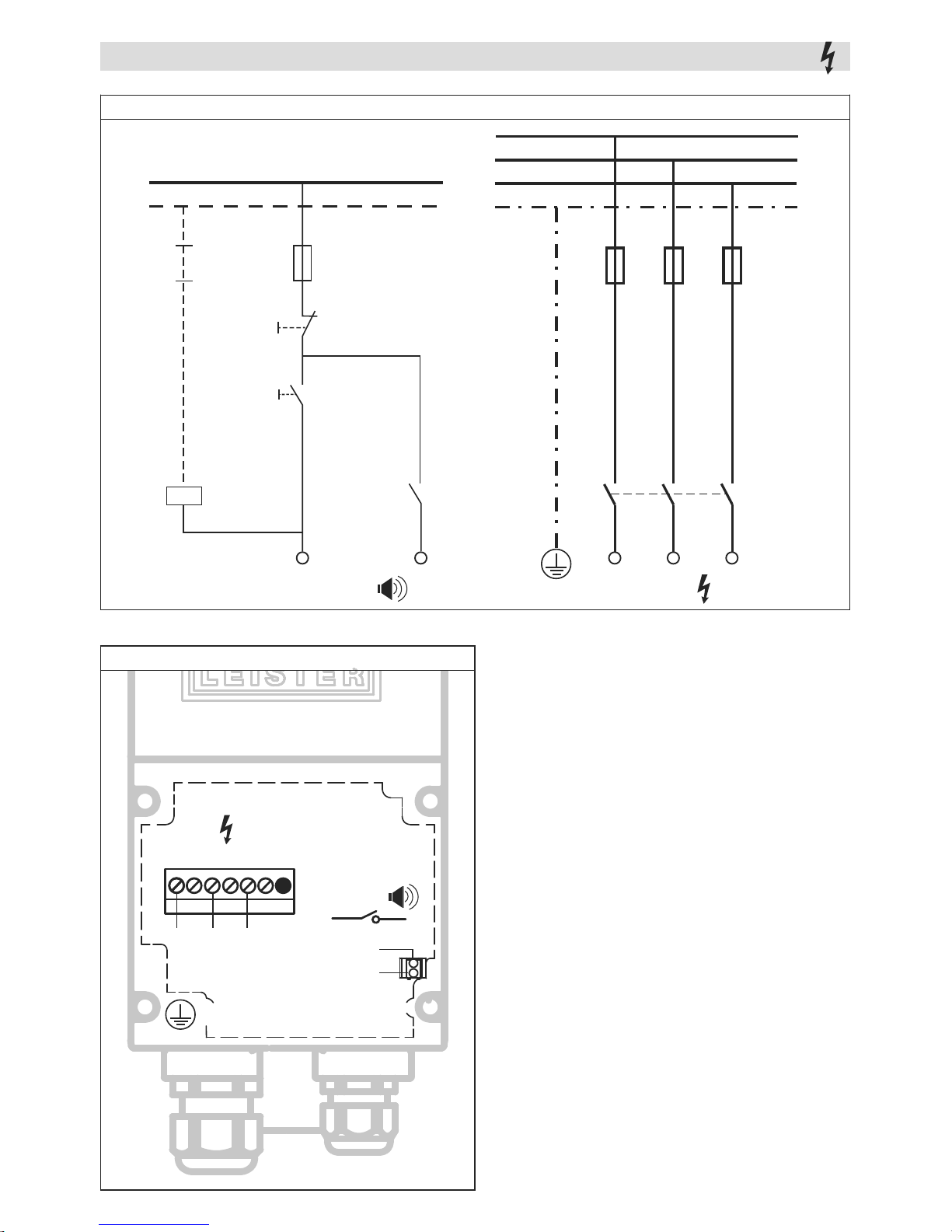
7
Wiring Diagram CLASSIC
LHS 15, 21 S, 21 L, L41 S, 41 L
L2 / N
L1
Power
L2 / N
L1
Alarm
ON
F2
L
HE
Power
F1
max 3A
NO
OFF
COM
K1
K1
K1
–
SSR
~
+
L2 / NL1
F2
K1
L
HE
LHS 15, 21 S, 21 L LHS 41 S, 41 L
L1
N
NO
COM
Alarm
Power
L
HE
L1
Alarm
NO
COM
L1
L2/N
Power
L1
L
HE
with SSR without SSR
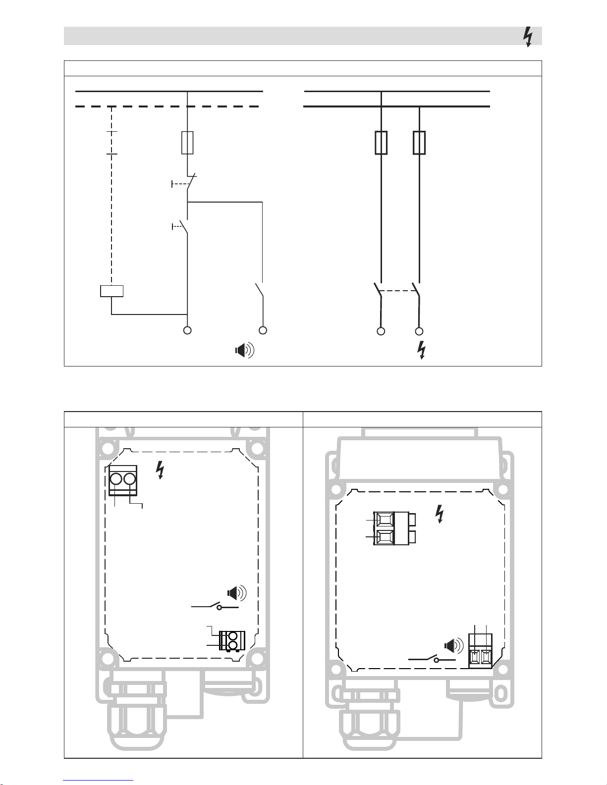
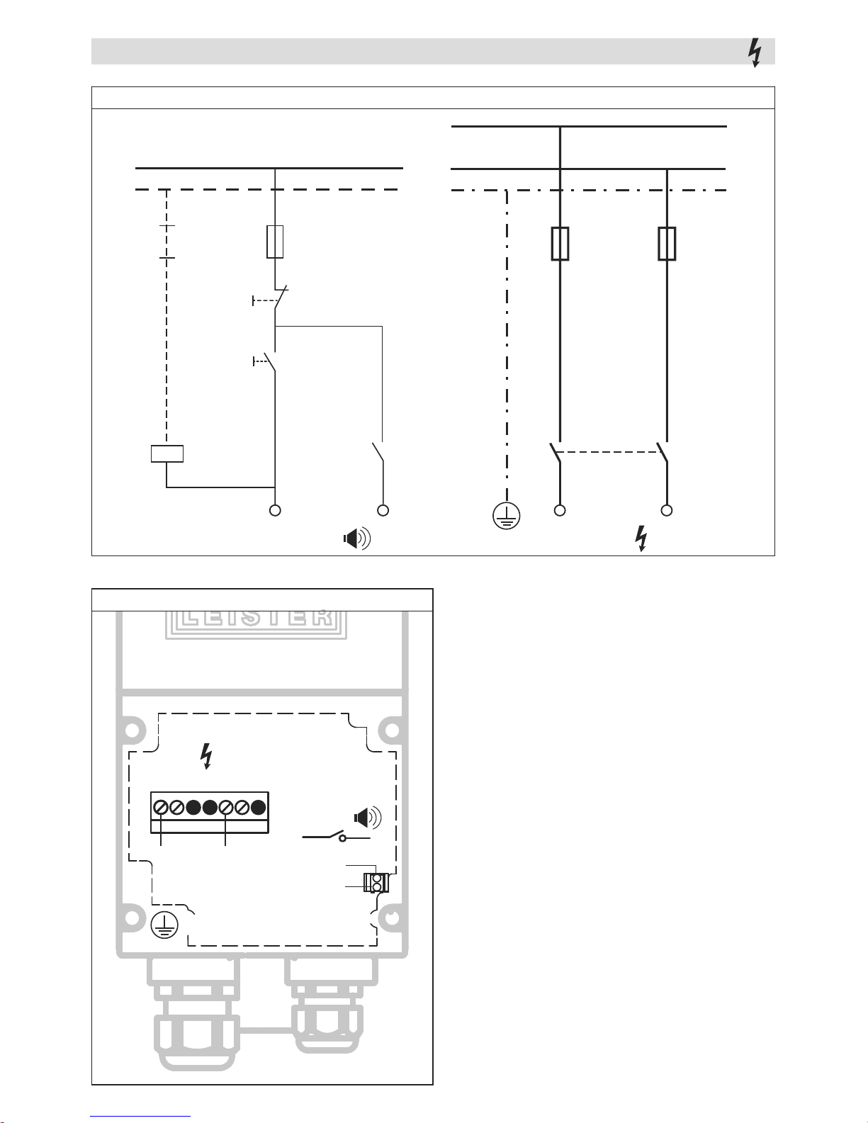
8
Wiring Diagram PREMIUM, SYSTEM
LHS 15, 21 S, 21 L, L41 S, 41 L
L2 / N
L1
Power
L2 / NL1
Alarm
ON
F2
F1
max 3A
NO
OFF
COM
K1
K1 K1
LHS 15, 21 S, 21 L LHS 41 S, 41 L
L1
N
NO
COM
Alarm
Power
Alarm
NO
COM
L1
L2/N
Power

LHS 61 S, 61 L / 3 × 230 – 3 × 480 V~
Alarm
ON
F1
max 3A
NO
OFF
COM
K1
K1
S1
S2
N
P
K1
PE
L1
Power
L1
F2
L2
L3
L2 L3
P
–
SSR
~
+
–
SSR
~
+
9
Wiring Diagram CLASSIC
LHS 61 S, 61 L / 3 × 230 – 3 × 480 V~
Power
Alarm
NO
COM
L1 L2
L3
PE
P
with SSR
K1
P
E
L1
Power
L1
F2
L
2
L
3
L2 L3
P
without SSR
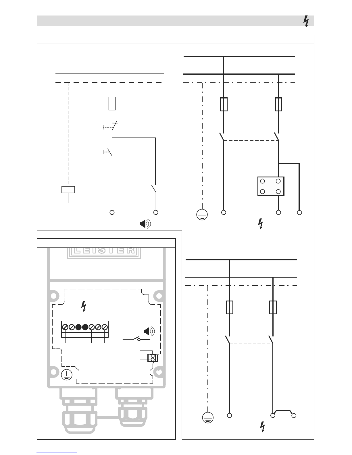
10
LHS 61 S / 400 – 480 V~
Alarm
ON
F1
max 3A
NO
OFF
COM
K1
K1
S1
S2
N
P
K1
PE
L1
Power
L1
F2
L3
L3
P
–
SSR
~
+
Wiring Diagram CLASSIC
LHS 61 S / 400 – 480 V~
Power
Alarm
NO
COM
L1
L3
PE
P
with SSR
K1
P
E
L1
Power
L1
F2
L3
L3
P
without SSR
11
Wiring Diagram PREMIUM, SYSTEM
LHS 61 S, 61 L / 3 × 230 – 3 × 480 V~
Alarm
ON
F1
max 3A
NO
OFF
COM
K1
K1
K1
PE
L1
Power
L1
F2
L2
L3
L2 L3
S1
S2
N
P
LHS 61 S, 61 L / 3 × 230 – 3 × 480 V~
Power
Alarm
NO
COM
L1 L2
L3
PE
12
Wiring Diagram PREMIUM, SYSTEM
LHS 61 S / 400 – 480 V~
Alarm
ON
F1
max 3A
NO
OFF
COM
K1
K1
K1
PE
L1
Power
L1
F2
L3
L3
S1
S2
N
P
LHS 61 S / 400 – 480 V~
Power
Alarm
NO
COM
L1
L3
PE
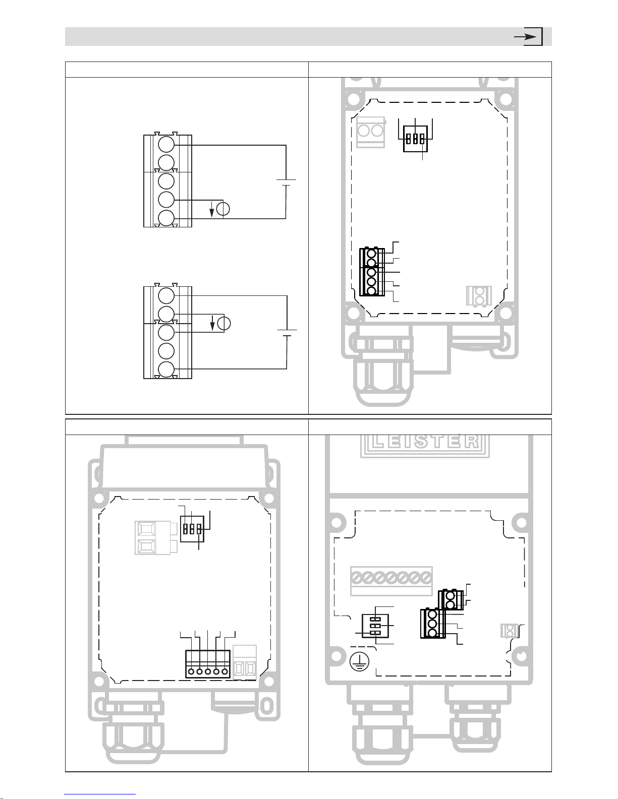
13
Interface SYSTEM
LHS 41 S, 41 L LHS 61 S, 61 L
Int
erface
0-1
0V
GND
+ 4-20mA
1
NO
3
2
– 4-20mA
24VDC
1
NO
3
2
0-10V
Int
erface
4-20mA –
24
VDC
4-20mA +
G
N
D
PE
LHS 15, 21 S, 21 L, 41 S, 41 L, 61 S, 61 L LHS 15, 21 S, 21 L
0-10V
4-20mA –
24VDC
4-2
0mA +
G
N
D
Input 4
– 20mA
Us
I
c
Us
Uc
0
-10V
Input 0
– 10
V
4-20mA –
24VDC
4-20mA +
GND
0-10V
Int
erface
4-20mA –
24VDC
4-20mA +
GND
1
NO
3
2
Bedienungsanleitung
(Original-Bedienungsanleitung)
14
Die Leister Lufterhitzer LHS eignen sich für den Einbau in Maschinen, Anlagen oder Geräte und sind
für den Dauerbetrieb ausgelegt.
• Trocken- und Aufheizprozesse verschiedenster Art
• Schrumpfen und Schweissen von Verpackungsfolien und Formteilen
• Heizen von Durchlauföfen und Behältern
• Aktivieren und Lösen von lösungsmittelfreien Klebstoffen und Schmelzklebern
• Sterilisieren von Verpackungsmaterialien wie Flaschen, Korken und Behältern
• Trennen und Verschmelzen von synthetischen Fäden und Geweben
• Lötvorgänge an dünnen Blechteilen
• Beschleunigen von Mischprozessen und Auflösen von Schäumen, die beim
Mischen oder bei Abfüllvorgängen entstehen
• Schweissen von thermoplastischen Kunststoffen
• Entfernen von Kunststoff-Pressgrat
• Glänzen der Kunststoff-Oberflächen
Anwendung
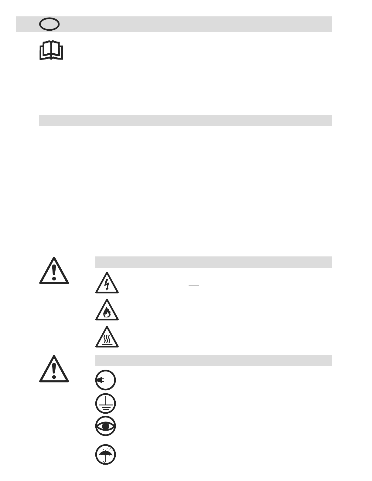
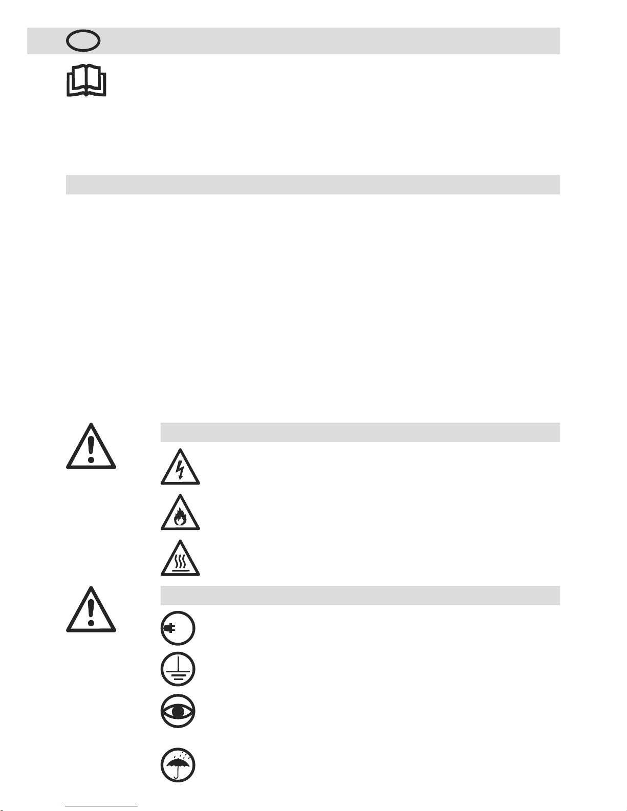
Bedienungsanleitung vor Inbetriebnahme aufmerksam
lesen und zur weiteren Verfügung aufbewahren.
D
Lebensgefahr beim Öffnen des Gerätes, da spannungsführende Komponenten und
Anschlüsse freigelegt werden. Vor dem Öffnen des Gerätes muss dieses all
-
polig vom Netz getrennt werden.
Feuer- und Explosionsgefahr bei unsachgemässem Einbau und Gebrauch von
Lufterhitzern, besonders in der Nähe von brennbaren Materialien und explosiven
Gasen.
Verbrennungsgefahr! Heizelementrohr und Düse nicht in heissem Zustand berühren. Gerät abkühlen lassen. Heissluftstrahl nicht auf Personen oder Tiere
richten.
Warnung
Gerät muss beobachtet betrieben werden.
Wärme kann zu brennbaren Materialien gelangen, die sich ausser Sichtweite
befinden. Gerät darf nur von ausgebildeten Fachleuten oder unter deren Aufsicht
benützt werden. Kindern ist die Benützung gänzlich untersagt.
Nennspannung, die auf dem Gerät angegeben ist, muss mit der Netzspannung
übereinstimmen.
IEC/EN 61000-3-11; Z
max
= 0.065Ω + j 0.040Ω. Gegebenenfalls
Elektrizitäts-
Versorgungs-Unternehmen konsultieren.
Gerät vor Feuchtigkeit und Nässe schützen.
100
480
Vorsicht
Gerät der Schutzklasse I muss mit Schutzleiter geerdet werden.
Lufterhitzer
LHS 15; LHS 21 S; LHS 21 L; LHS 41 S; LHS 41 L; LHS 61 S; LHS 61 L
CLASSIC, PREMIUM oder SYSTEM

15
(Im Sinne der EG-Maschinenrichtlinie 2006/42; Anhang II B)
Leister Technologies AG, Galileo-Strasse 10, CH-6056 Kaegiswil/Schweiz erklärt hiermit, dass die unvoll -
ständige Maschine
Bezeichnung: Lufterhitzer
Typ: LHS 15; LHS 21S; LHS 21L; LHS 41S; LHS 41L; LHS 61S; LHS 61L
Ausführung: CLASSIC, PREMIUM oder SYSTEM
– soweit es vom Lieferumfang her möglich ist – den anwendbaren grundlegenden Anforderungen der EG-Maschinen richtlinie (2006/42) entspricht.
Die unvollständige Maschine entspricht überdies den Anforderungen der folgenden EG-Richtlinie(n):
EG-Richtlinie(n): Elektromagnetische Verträglichkeit 2004/108
Niederspannungsrichtlinie 2006/95
RoHS - Richtlinie 2011/65
Harmonisierte Normen: EN 12100, EN 55014-1, EN 55014-2, EN 61000-6-2,
EN 61000-3-2,
EN 61000-3-3,
EN 61000-3-12,
EN 61000-3-11 (Z
max
),
EN 62233, EN 60335-2-45, EN 50581
Ferner erklären wir, dass für diese unvollständige Maschine die speziellen technischen Unterlagen gemäss
Anhang VII (Teil B) erstellt wurden und verpflichten uns, diese auf begründetes Verlangen den Marktüberwachungsbehörden elektronisch zu übermitteln.
Name des Dokumentationsbevollmächtigten: Volker Pohl, Manager Product Conformity
Die Inbetriebnahme der unvollständigen Maschine wird so lange untersagt, bis gegebenenfalls festgestellt wurde,
dass die Maschine, in die die unvollständige Maschine eingebaut wurde, den Bestimmungen der EG-Maschinenrichtlinie (2006/42) entspricht.
Kaegiswil, 13.06.2014
Bruno von Wyl, CTO Andreas Kathriner, GM
Elektrowerkzeuge, Zubehör und Verpackungen sollen einer umweltgerechten Wiederverwertung zugeführt werden. Nur für EU-Länder: Werfen Sie Elektrowerkzeuge nicht in den Hausmüll! Gemäß der
Europäischen Richtlinie 2002/96 über Elektro- und Elektronik-Altgeräte und ihrer Um setzung in nationales Recht müssen nicht mehr gebrauchsfähige Elektrowerkzeuge getrennt gesammelt und einer umweltgerechten Wiederverwertung zugeführt werden.
Entsorgung
Einbauerklärung

16
Technische Daten
CLASSIC PREMIUM SYSTEM
Detektion von Heizelement- und Geräteüberhitzung mit Alarmausgang •
Heizleistung mit Potentiometer stufenlos einstellbar • •
Integrierte Leistungselektronik • •
Schutz vor Heizelement- und Geräteüberhitzung mit Alarmausgang • •
Integrierter Temperaturregler •
Schnittstelle für Temperatur- oder Leistungsvorgabe •
Integrierte Temperatursonde •
Display zur Anzeige der Soll- und Istwerte (°C oder °F) •
Typ LHS 15 21 S 21 L 41 S 41 L 61 S 61 L 61 S
Spannung V~
120 –
230
120 –
230
230
120 –
230
230 –
400
3 × 230 –
3 × 480
–
3 × 230 –
3 × 480
–
400 –
480
Frequenz Hz
50 / 60 50 / 60 50 / 60 50 / 60 50 / 60 50 / 60 50 / 60 50 / 60
Leistung kW
0.55–
0.77
1.0–
2.0
3.3
2.0–
3.6
2.0–
5.5
4.0– 9.0 5.0–16.0 8.0– 8.5
Min. Luftmenge l/min.
60 120 240 240
240 –
500
360 500 800
Max. Luftdruck Pa
1 × 1051 × 1051 × 1051 × 1051 × 1051 × 10
5
1 × 10
5
1 × 10
5
Max. Temperatur °C
650 650 650 650 650 650 650 650
Max. UmgebungsTemperatur °C
65 65 65 65 65 65 65 65
Min. ZuluftTemperatur °C
0 0 0 0 0 0 0 0
Max. ZuluftTemperatur °C
65 65 65 65 65 65 65 65
Emissionspegel LpA(dB) <70 <70 <70 <70 <70 <70 <70 <70
Gewicht kg
0.4 0.5 0.6 0.8 0.9 3.2 3.7 3.2
Konformitätszeichen
2 2 2 2 2 2 2 2
Sicherheitszeichen
3 3 3 3 3 3 3 3
Schutzklasse I
1 1 1
Schutzklasse II
4 4 4 4 4
Technische Änderungen vorbehalten

17
CLASSIC, PREMIUM, SYSTEM
Relaisausgang
Max. Spannungen AC 250 V, DC 30 V
Max. Ströme AC 3 A, DC 3 A
Max. Kontaktwiderstand 100 m Ohm bei DC 6 V / 1 A
Kontaktart SPST - NO
Isolation IEC/EN 60065 AC 2000 V (50 - 60 Hz) 1 min
Technische Daten Schnittstellen
Konfiguration interner Kodierschalter (nur SYSTEM)
Open Loop oder Closed Loop
Stellfunktion Leistung
Stellgrad OFF…100 %;
1% Schritte
Reglerfunktion Temperatur
Sollwertvorgabe 50 °C…650 °C,
5 °C Schritte
Sollwertvorgabe
Potentiometer oder
Schnittstelle
Internes Potentiometer
Sollwert OFF…100 % oder
50 °C …650 °C
Schnittstelle
Sollwert OFF…100 % oder
50 °C …650 °C
SYSTEM
Signaleingänge
mit Verpolungsschutz und
Nullpunktkorrektur
Isolation IEC/EN 60747-5-2
AC 1414 V Peak
Spannungseingang Uc bezogen
auf GND iso
DC 0 - 10 V
(Rippel < 0.05 V bei
5 °C Auflösung)
(Rippel < 0.1 V bei
1 % Auflösung)
Max. Eingangsspannung
DC 12 V
Nenn-Eingangswiderstand
280 kOhm
Stromeingang Ic (2 - Leiter Technik)
DC 4…20 mA
(Rippel < 0.1 mA bei
5 °C Auflösung)
(Rippel < 0.15 mA bei
1 % Auflösung)
Max. Eingangsstrom
DC 22 mA
Nenn-Eingangswiderstand
160 Ohm
Speisung
mit Verpolungsschutz
ohne Trennung von den
Signaleingängen
Betriebsspannung Us bezogen auf
GND iso
DC 15…24 V
Max. Betriebsspannung
DC 25 V
Stromaufnahme
12 mA bei DC 24 V

18
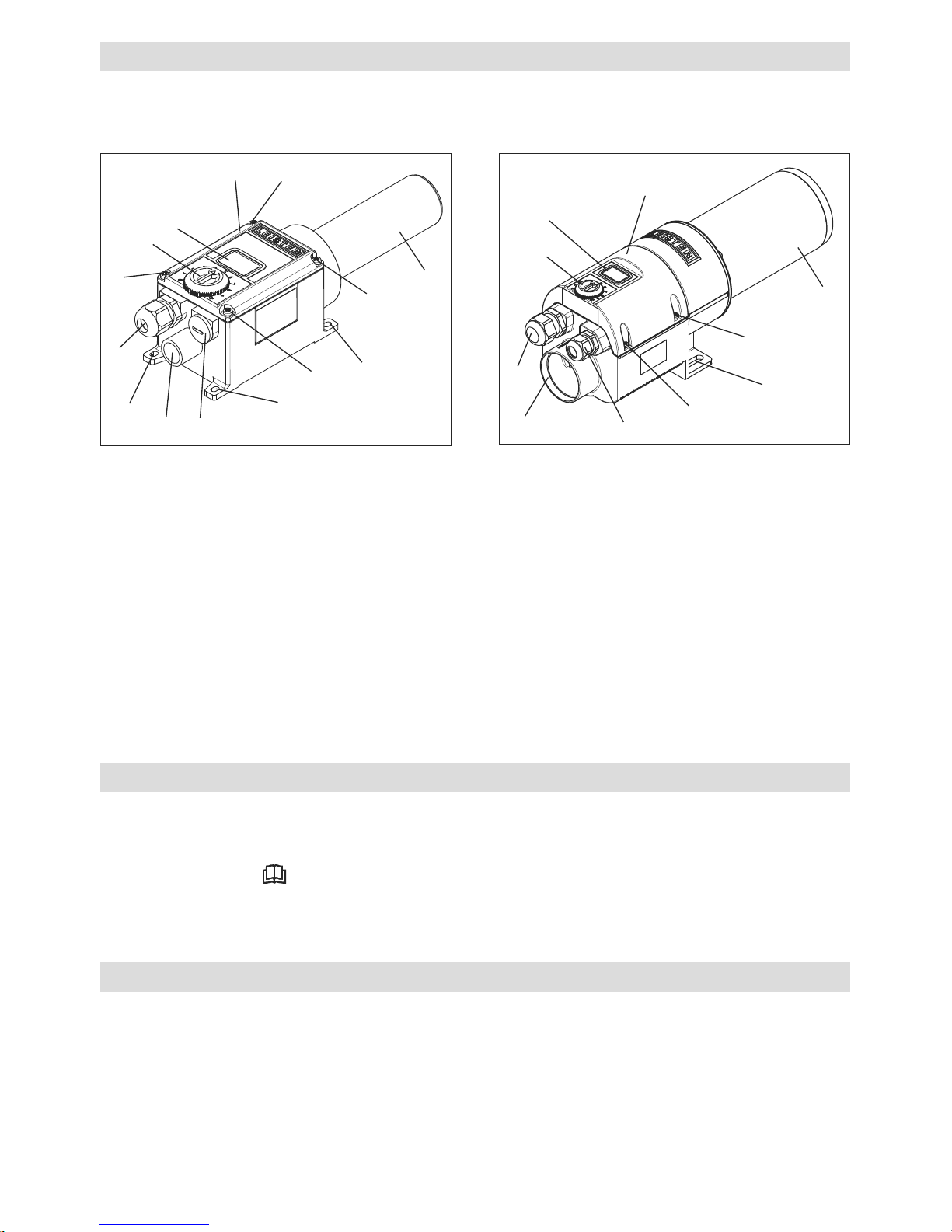
Gerätebeschreibung
CLASSIC, PREMIUM, SYSTEM
1 Montagelaschen
2 Abdeckung Anschlussgehäuse
3 Schrauben für Anschlussgehäuse
4 Heizelementrohr
5 Kabelverschraubung für Netzanschluss
(Ab Werk montiert)
6 Verschlussschraube
(beigepackt im Anschlussgehäuse)
7 Kabelverschraubung für Schnittstelle
8 Einblasstutzen
LHS 15, LHS 21 S, LHS 21 L, LHS 41 S, LHS 41 L:
CLASSIC, PREMIUM, SYSTEM
LHS 61L, LHS 61 S:
CLASSIC, PREMIUM, SYSTEM
1
1
1
1
4
4
2
2
3
3
3
3
3
3
5
5
7
6
8
8
9
9
PREMIUM, SYSTEM
9 Potentiometer für Temperatureinstellung
SYSTEM
10 Display zur Anzeige der Soll- und Ist-Werte
(°C oder °F)
10
• Lufterhitzer LHS aus der Verpackung entnehmen.
• Durch Lösen der Schrauben (3) die Abdeckung Anschlussgehäuse (2) entfernen.
• Warnzettel entnehmen, aufmerksam lesen und zur weiteren Verfügung aufbewahren.
• Verschlussschraube (6) entnehmen.
• Wird keine Schnittstelle verwendet, muss die Kabelverschraubung (7) entfernt und die Verschlussschraube (6)
montiert werden.
• Der Einbau muss gewährleisten, dass
– nur kalte Luft zugeführt wird.
– kein (Wärme-) Rückstau entsteht.
– das Gerät nicht vom Heissluftstrahl eines anderen Gerätes angeströmt wird.
• Das Gerät vor mechanischen Vibrationen und Erschütterungen schützen.
• Das Gerät an den Montagelaschen (1) befestigen.
• Einbaumasse siehe Seiten 3, 4, 5, 6 (Size)
Vorbereitung
Einbau
10
19
• Um Gerät und Heizelement zu schützen, darf die vorgeschriebene minimale Luftmenge keinesfalls unterschritten
und die maximale Temperatur (heissester Punkt 3 mm vor dem Heizelementrohr gemessen) keinesfalls überschritten werden (siehe technische Daten). Falls die minimale Luftmenge unterschritten wird, muss sofort die
Heizleistung unterbrochen werden.
• Luftdurchflussrichtung beachten.
• Als Luftversorgung müssen Leister-Gebläse verwendet werden (Drehrichtung und Kompressionserwärmung
beachten).
• Beim Druckluftanschluss darf der maximale Luftdruck nicht überschritten werden (siehe technische Daten).
• Bei staubhaltiger Luft Leister Edelstahlfilter am Gebläse-Ansaugstutzen verwenden. Bei besonders kritischen
Stäuben (z.B. Metall-, elektrisch leitende oder feuchte Stäube) müssen spezielle Filter verwendet werden,
um Kurzschlüsse im Gerät zu vermeiden.
• Der Lufterhitzer LHS muss durch Fachpersonen angeschlossen werden.
• Im Netzanschluss muss eine geeignete Vorrichtung zur allpoligen Trennung vom Netz vorhanden sein !
• Es muss sichergestellt sein, dass die Anschlussleitungen das Heizelementrohr nicht berühren und dem Heissluft-
strahl nicht ausgesetzt sind.
• Das Gerät muss gemäss dem Anschlussschema und der Klemmanordnung auf Seiten 7, 8, 9, 10, 11, 12
(Wiring Diagram) und Seite 13 (Interface) der Bedienungsanleitung angeschlossen werden:
– Verdrahtung im Anschlussgehäuse (2) vornehmen.
• ACHTUNG: Für Lufterhitzer LHS SYSTEM die Einstellungen des Kodierschalters prüfen (siehe Kapitel Betrieb).
• Abdeckung Anschlussgehäuse (2) mit den Schrauben (3) montieren.
• Lufterhitzer LHS an das elektrische Netz anschliessen.
• Nach Bedarf entsprechende Düse montieren.
• Es muss darauf geachtet werden, dass die Heissluft frei ausströmen kann, da ansonsten durch Wärmerückstau
das Gerät Schaden erleiden kann (Brandgefahr !).
• Achtung: Minimale Luftmenge gemäss technischen Daten einhalten.
• Netz einschalten.
• Gerät nach dem Heizbetrieb nachkühlen lassen.
LHS CLASSIC
• Zum Betrieb mit permanent maximaler Heizleistung (muss auf die Luftmengen-Zufuhr abgestimmt sein)
• Zum Betrieb mit externer Leistungssteuerung (zum Beispiel mit Halbleiterrelais, SSR).
• Hinweis:
– Unterschiedliche Verdrahtung mit SSR (with SSR) oder ohne SSR (without SSR) beachten. Siehe Wiring Diagramm
auf Seite 7, 9 und Seite 10.
– Das Gerät muss bei Ansprechen der Überhitzungsdetektion über eine geeignete externe Beschaltung vom Netz
getrennt werden.
LHS PREMIUM
• Stufenlos einstellbare Heizleistung mittels rotem Potentiometer auf dem Gerät.
• Das Gerät ist mit integriertem Heizelement- und Geräteschutz ausgestattet
(siehe Kapitel Funktion Heizelement- Geräteschutz.
Luftversorgung
Anschluss
Achtung: Gerät immer mit Luftversorgung betreiben !
Betrieb
20
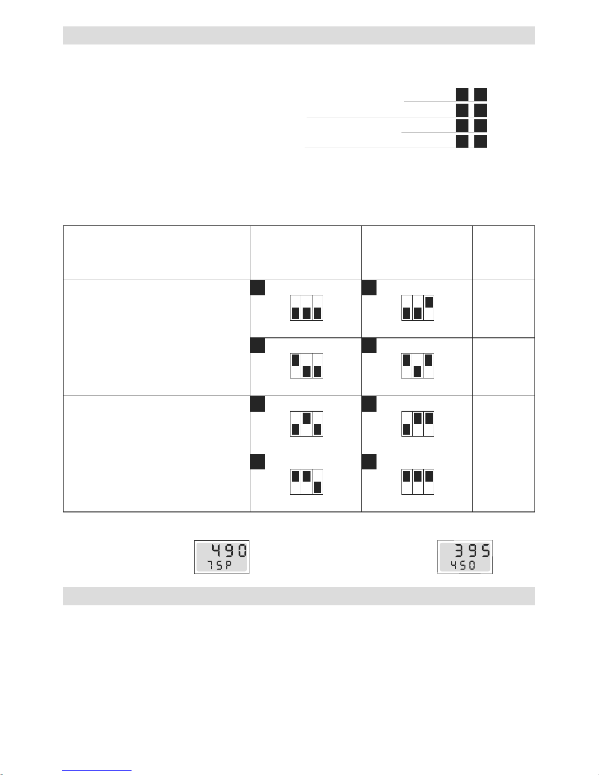
°C
Istwert
Sollwert %
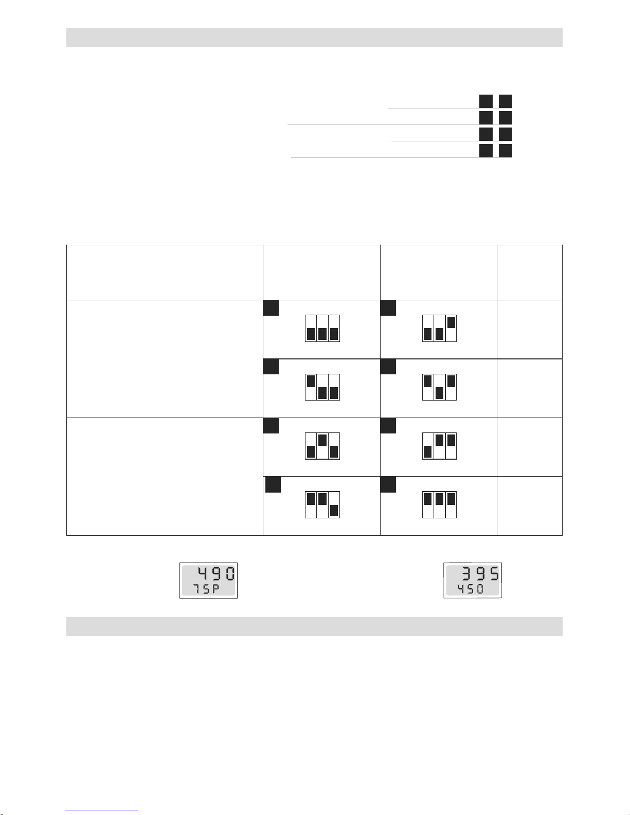
Modus gesteuert
Das Display zeigt Leistungs sollwert in % und Istwert der
Temperatur an
LHS SYSTEM
• Wahlweise unterschiedliche Betriebsmodi, welche mit integriertem Kodierschalter eingestellt werden
– Stufenlos einstellbare Heizleistung mittels rotem Potentiometer auf dem Gerät
– Stufenlos einstellbare Heizleistung mittels Schnittstelle
– Stufenlos einstellbare Temperatur mittels rotem Potentiometer auf dem Gerät
– Stufenlos einstellbare Temperatur mittels Schnittstelle
– Integrierte Temperaturanzeige in °C oder °F
• Das Gerät ist mit integriertem Heizelement und Geräteschutz ausgestattet
(siehe Kapitel Funktion Heizelement- Geräteschutz.
• Einstellungen zur Selektion der verschiedenen Betriebsmodi:
Betrieb
1 2
3 4
5 6
7 8
Schalter 1: °C oder °F
Schalter 2: Potentiometer oder Schnittstelle
Schalter 3: Gesteuert oder geregelt
Modus gesteuert
(Leistungsvorgabe)
Modus geregelt
(Temperaturvorgabe)
Anzeige
Potentiometer Modus
ON
123
ON
123
°C
ON
123
ON
123
°F
Schnittstellen Modus
ON
123
ON
123
°C
ON
123
ON
123
°F
• Überhitzt das Heizelement oder Gerät (zu warme Zuluft oder Wärmerückstau) wird die Leistungszufuhr zum
Heizelement unterbrochen und der Arbeitskontakt des Alarmrelais geöffnet. Nach Ansprechen des Heizelementschutzes oder Geräteschutzes ist aus Sicherheitsgründen ein Rückstellen (Reset) des Lufterhitzers nötig !
• WICHTIG: Massnahmen beim Ansprechen des Heizelement- oder Geräteschutzes
– Gerät 10 Sekunden vom Netz trennen
– Luftzufuhr überprüfen
– Luftmenge überprüfen
– Luftdurchlass überprüfen
– Gerät wieder mit Netz verbinden
Funktion Heizelement- Geräteschutz
1
2
3
4
5
6
7
8
°C
Istwert
Sollwert
Modus geregelt
Das Display zeigt
Ist- und Sollwert
der Temperatur an
21
Leister Technologies AG sowie deren autorisierte Service-Stellen bieten kostenlose Kurse im Bereich der
Anwendungen an.
3D-Zeichnungen der Lufterhitzer LHS-Linie sind bei ihrer Service-Stelle oder auf www.leister.com erhältlich.
• Es darf nur Leister-Zubehör verwendet werden.
• Leister bietet ein grosses Sortiment an Zubehör, z.B.
– Temperaturregler
– Düsen
– Gebläse
• Zubehör unter www.leister.com
• Reparaturen sind ausschliesslich von autorisierten Leister Service-Stellen ausführen zu lassen. Diese gewähr-
leisten innert nützlicher Frist einen fachgerechten und zuverlässigen Reparatur-Service mit Original-Ersatzteilen
gemäss Schaltplänen und Ersatzteillisten.
Service und Reparatur
3D Zeichnungen
Zubehör
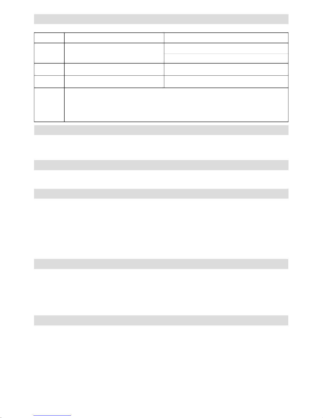
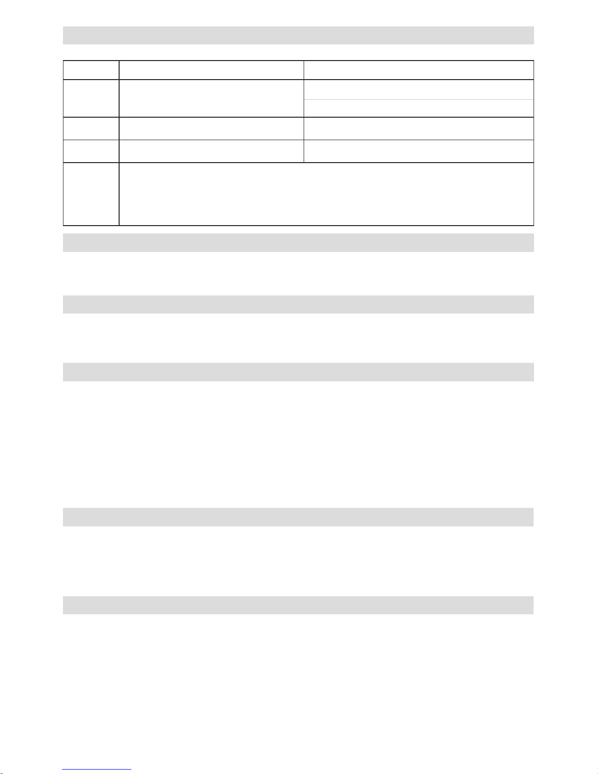
Display Bezeichnung Fehlerbehebung
Err 01 Gerätetemperatur zu hoch Umgebungstemperatur prüfen
Zulufttemperatur prüfen
Err 02 Heizelement temperatur zu hoch Luftmenge prüfen
Err 03 Temperatursonde Anschluss der Temperatursonde kontrollieren
Err 04
Err 05
Err 06
Err 07
Leister Service-Stelle kontaktierten
Error
Schulung
Gewährleistung
• Für dieses Gerät gelten die vom direkten Vertriebspartner/Verkäufer gewährten Garantie- oder Gewährleistungsrechte
ab Kaufdatum. Bei einem Garantie- oder Gewährleistungsanspruch (Nachweis durch Rechnung oder Lieferschein)
werden Herstellungs- oder Verarbeitungsfehler vom Vertriebspartner durch Ersatzlieferung oder Reparatur beseitigt.
Heizelemente sind von der Gewährleistung oder Garantie ausgeschlossen.
• Weitere Garantie- oder Gewährleistungsansprüche werden im Rahmen des zwingenden Rechts ausgeschlossen.
• Schäden, die auf natürliche Abnutzung, Überlastung oder unsachgemässe Behandlung zurückzuführen sind, werden
von der Gewährleistung ausgeschlossen.
• Keine Garantie- oder Gewährleistungsansprüche bestehen bei Geräten, die vom Käufer umgebaut oder verändert
wurden.
Operating Instructions
(Translation of the original operating instructions)
22
The Leister LHS air heaters are suitable for building into machines, installations or appliances and are
designed for continuous operation.
• Drying and heating processes of various types
• Shrinking and welding packaging films and moulded parts
• Heating conveyor ovens or heat tunnels
• Activating and loosening solvent free adhesives and melt adhesives
• Sterilizing packaging materials such as bottles, corks and containers
• Separating and fusing synthethic fibres and fabrics
• Soldering processes on thin metal parts
• Speeding up mixing processes and dissolving foams which can arise during mixing and filling operations
• Welding thermoplastic materials
• Removing plastic mould flash
• Putting a shine on plastic surfaces
Application
Please read operating instructions carefully before use
and keep for future reference.
GB
Danger of death when opening the device, as live parts and connections are exposed. The device must be fully
disconnected from the mains before opening it.
Danger of fire and explosion if air heaters are installed and used incorrectly, especially in the vicinity of flammable materials and explosive gases.
Danger – can cause burns! Do not touch the heating element tube and nozzle
while they are hot. Allow the device to cool. Do not direct hot-air jet towards
people or animals.
Warning
The device must not be left unattended when in use.
Heat can reach combustible materials which are out of sight. The device may only
be used by trained personnel or under their supervision. Children may not use the
device under any circumstances.
The nominal voltage indicated on the device must correspond to the mains voltage.
IEC/EN 61000-3-11; Z
max
= 0.065Ω + j 0.040Ω. If necessary, consult electricity
supply utilty.
Keep away from wet and damp areas.
100
480
Caution
Devices of protection class I must be earthed with a protective earth conductor.
Air heaters
LHS 15; LHS 21 S; LHS 21 L; LHS 41 S; LHS 41 L; LHS 61 S; LHS 61 L
CLASSIC, PREMIUM or SYSTEM
23
(As defined by the EC Machinery Directive 2006/42; Annex II B)
Leister Technologies AG, Galileo-Strasse 10, CH-6056 Kaegiswil/Switzerland hereby declares that the
incomplete machine
Designation: Air heater
Type: LHS 15; LHS 21S; LHS 21L; LHS 41S; LHS 41L; LHS 61S; LHS 61L
Version: CLASSIC, PREMIUM or SYSTEM
– insofar as is possible from the scope of supply – corresponds to the applicable fundamental requirements of the
EC Machinery Directive (2006/42).
The incomplete machine furthermore corresponds to the requirements of the following EC directive(s):
EC directive(s): Electromagnetic Compatibility 2004/108
Low Voltage Directive 2006/95
RoHS Directive 2011/65
Harmonised standards: EN 12100, EN 55014-1, EN 55014-2, EN 61000-6-2,
EN 61000-3-2,
EN 61000-3-3,
EN 61000-3-12,
EN 61000-3-11 (Z
max
),
EN 62233, EN 60335-2-45, EN 50581
We furthermore declare that the special technical documents pursuant to Annex VII (Part B) have been compiled for this incomplete machine and that we are committed to communicate these electronically to the market surveillance authorities upon justified request.
Name of the documentation officer: Volker Pohl, Manager Product Conformity
The commissioning of the incomplete machine is prohibited until it may be determined that the machine in which
the incomplete machine has been installed corresponds to the provisions of the EC Machinery Directive (2006/42).
Kaegiswil, 13.06.2014
Bruno von Wyl, CTO Andreas Kathriner, GM
Power tools, accessories and packaging should be recycled. For EU countries only: do not dispose
of power tools in your household rubbish! According to the European Directive 2002/96 on waste electrical and electronic equipment and its implementation in national law, power tools which can no longer
be used must be collected separately and recycled.
Disposal
Installation declaration

24
Technical data
CLASSIC PREMIUM SYSTEM
Detection of heating element and device overheating with alarm output •
Heat output steplessly adjustable with potentiometer • •
Integrated power electronics • •
Protection of heating element and device overheating with alarm output • •
Integrated temperature controller •
Interface for temperature or power set point •
Integrated temperature probe •
Display showing setpoint and actual values (°C or °F) •
Type LHS 15 21 S 21 L 41 S 41 L 61 S 61 L 61 S
Voltage V~
120 –
230
120 –
230
230
120 –
230
230 –
400
3 × 230 –
3 × 480
–
3 × 230 –
3 × 480
–
400 –
480
Frequency Hz
50 / 60 50 / 60 50 / 60 50 / 60 50 / 60 50 / 60 50 / 60 50 / 60
Power consumption kW
0.55–
0.77
1.0–
2.0
3.3
2.0–
3.6
2.0–
5.5
4.0– 9.0 5.0–16.0 8.0– 8.5
Min. air volume l/min.
60 120 240 240
240 –
500
360 500 800
Max. air pressure Pa
1 × 1051 × 1051 × 1051 × 1051 × 1051 × 10
5
1 × 10
5
1 × 10
5
Max. temperature °C
650 650 650 650 650 650 650 650
Max. ambient
temperature °C
65 65 65 65 65 65 65 65
Min. inlet air
temperature °C
0 0 0 0 0 0 0 0
Max. inlet air
temperature °C
65 65 65 65 65 65 65 65
Emission level LpA (dB) <70 < 70 <70 <70 <70 <70 <70 <70
Weight kg
0.4 0.5 0.6 0.8 0.9 3.2 3.7 3.2
Conformity mark
2 2 2 2 2 2 2 2
Safety standard
3 3 3 3 3 3 3 3
Protection class I
1 1 1
Protection class II
4 4 4 4 4
Technical data and specifications are subject to change without prior notice

25
CLASSIC, PREMIUM, SYSTEM
Relay output
Max. voltages AC 250 V, DC 30 V
Max. currents AC 3 A, DC 3 A
Max. contact resistance 100 m Ohm at DC 6 V / 1 A
Type of contact SPST - NO
Insulation IEC/EN 60065 AC 2000 V (50 - 60 Hz) 1 min
Technical data for interfaces
Configuration of internal dip switch (only SYSTEM)
Open Loop or Closed Loop
Power setting function
Setting level OFF…100 %;
1% steps
Temperature control function
Setpoint value specification
50 °C…650 °C, 5 °C steps
Setpoint setting
Potentiometer or
interface
Internal potentiometer
Setpoint value OFF…100 % or
50 °C …650 °C
Interface
Setpoint value OFF…100 % or
50 °C …650 °C
SYSTEM
Signal inputs
with reverse polarity protection
and zero oset
Insulation IEC/EN 60747-5-2
AC 1414 V Peak
Voltage input Uc in relation
to GND iso
DC 0 - 10 V
(Ripple < 0.05 V at
5 °C resolution)
(Ripple < 0.1 V at
1 % resolution)
Max. input voltage
DC 12 V
Nominal input resistance
280kOohm
Current input Ic (2 - conductor
technology)
DC 4…20 mA
(Ripple < 0.1 mA at
5 °C resolution)
(Ripple < 0.15 mA at
1 % resolution)
Max. input current
DC 22 mA
Nominal input resistance
160 Ohm
Supply
with reverse polarity protection
without separation of the
signal inputs
Operating voltage Us in relation to
GND iso
DC 15…24 V
Max. operating voltage
DC 25 V
Power consumption
12 mA at DC 24 V
26
Device description
CLASSIC, PREMIUM, SYSTEM
1 Mounting straps
2 Connection housing cover
3 Screws for connection housing
4 Heating element tube
5 Cable gland for mains connection
(mounted ex works)
6 Locking screw
(enclosed in the connection housing)
7 Cable gland for interface
8 Air inlet
LHS 15, LHS 21 S, LHS 21 L, LHS 41 S, LHS 41 L:
CLASSIC, PREMIUM, SYSTEM
LHS 61L, LHS 61 S:
CLASSIC, PREMIUM, SYSTEM
1
1
1
1
4
4
2
2
3
3
3
3
3
3
5
5
7
6
8
8
9
9
PREMIUM, SYSTEM
9 Potentiometer for temperature setting
SYSTEM
10 Display for showing the setpoint and actual values
(°C or °F)
10
• Remove LHS air heater from the packaging.
• Remove the connection housing cover (2) by loosening the screws (3).
• Remove warning slip, read carefully and keep at hand for consultation.
• Remove locking screw (6).
• If no interface is connected, the cable gland (7) must be removed and the locking screw (6) mounted.
• The installation must ensure that
– only cold air is supplied.
– no excess (heat) residue builds up.
– the device is not subject to jets of hot air from another device.
• Protect the device from mechanical vibrations and shocks.
• Fasten the device on the mounting straps (1).
• For installation dimensions, see pages 3, 4, 5, 6 (Size)
Preparation
Installation
10
27
• In order to protect the device and heating element, the specified minimum air volume must never be fallen below
and the maximum temperature (hottest point measured 3 mm in front of the heating element tube) must never
be exceeded (see technical data). If the minimum air volume is fallen below, the heat output must be interrupted
immediately.
• Observe direction of air flow.
• Leister blowers must be used as an air supply (observe direction of rotation and compression preheating).
•
When operating with compressed air, the maximum air pressure must not be exceeded (see technical data).
• If the air contains dust, use a Leister stainless steel filter on the blower air intake. In the case of particularly
hazardous dusts (e.g. metal, electrically conductive or damp dusts), special filters must be used to avoid
short-circuits in the device.
• The LHS air heater must be connected by qualified personnel.
• A suitable device for full disconnection from the mains must be provided in the mains connection!
• It must be ensured that the connection lines do not come into contact with the heating element tube and are not
exposed to the hot air jet.
• The device must be connected in accordance with the connection diagram and the terminal arrangement
on pages 7, 8, 9, 10, 11, 12 (Wiring Diagram) and page 13 (Interface) of the operating instructions:
– Carry out wiring in the connection housing (2).
• ATTENTION: check dip switch settings of the LHS SYSTEM air heater (see chapter Operation).
• Mount connection housing cover (2) with the screws (3).
• Connect LHS air heater to the electrical mains.
• Mount corresponding nozzle, if required.
• It must be ensured that the hot air can flow out freely, as otherwise the device can be damaged by the excess
heat building up (risk of fire!).
• Attention: comply with minimum air volume as per technical data.
• Switch on mains.
• Allow device to cool down after heating mode.
LHS CLASSIC
• For operation with permanent maximum heat output (must be adapted to the air volume supply)
• For operation with external power control (for example with semiconductor relay, SSR).
• Note:
– Different wiring requirements for working with SSR or without. See wiring diagramm page 7, 9 and page 10.
– The device must be disconnected from the mains via a suitable external circuit if the overheating detection is
activated.
LHS PREMIUM
• Infinitely adjustable heat output via red potentiometer on the device.
• The device is fitted with an integrated heating element and device protection).
(see chapter Function of heating element - device protection.
Air supply
Connection
Attention: always operate device with air supply !
Operation
28
LHS SYSTEM
• Optionally different operating modes which are set with an integrated dip switch
– Steplessly adjustable heat output via red potentiometer on the device
– Steplessly adjustable heat output via interface
– Steplessly adjustable temperature via red potentiometer on the device
– Steplessly adjustable temperature via interface
– Integrated temperature display in °C or °F
• The device is fitted with an integral heating element and device protection
(see chapter Function of heating element - device protection).
• Settings for selecting the various operating modes:
Operation
1 2
3 4
5 6
7 8
Switch 1: °C or °F
Switch 2: Potentiometer or interface
Switch 3: Open Loop or Closed Loop
Open Loop
(power set point)
Closed Loop
(temperature
set point)
Display
Potentiometer mode
ON
123
ON
123
°C
ON
123
ON
123
°F
Interface mode
ON
123
ON
123
°C
ON
123
ON
123
°F
• If the heating element or device overheats (too hot inlet air or excess heat residue), the power supply to the
heating element will be interrupted and the working contact of the alarm relay opened. After the heating
element or device protection is activated, it will be necessary to reset the air heater for reasons of safety!
• IMPORTANT: measures to take when the heating element or device protection is activated
– Disconnect device from the mains for 10 seconds
– Check air supply
– Check air volume
– Check air flow
– Reconnect device to the mains
Function of heating element – device protection
1
2
3
4
5
6
7
8
°C
Actual temp
Setpoint %
Open Loop mode
Display shows power
setpoint in % and actual
temperature
°C
Actual temp
Setpoint
Closed Loop mode
Display shows setpoint
temperature and actual
temperature
29
Leister Technologies AG and its authorised service points provide free courses in the area of applications.
3D drawings of the LHS air heaters line are available from your service point or at www.leister.com
• Only Leister accessories may be used.
• Leister offers a wide range of accessories, e.g.
– Temperature controls
– Nozzles
– Blowers
• Accessories at www.leister.com
• Repairs should only be carried out by authorised Leister Service Centres. They guarantee a correct and reliable
repair service within reasonable period, using original spare parts in accordance with the circuit diagrams
and spare parts lists.
Service and repairs
3D drawings
Accessories
Display Description Fault correction
Err 01 Device temperature too high Check environment temperature
Check air intake temperature
Err 02 Heating element temperature too high Check air supply volume
Err 03 Temperature probe Check probe connection
Err 04
Err 05
Err 06
Err 07
Contact your Leister Service Centres
Error
Training
• For this tool, the guarantee or warranty rights granted by the relevant distributor/seller shall apply. In case of
guarantee or warranty claims any manufacturing or workmanship defects will either be repaired or replaced
by the distributor at its discretion. Warranty or guarantee rights have to be verified by an invoice or a delivery
document. Heating elements shall be excluded from warranty or guarantee.
• Additional guarantee or warranty claims shall be excluded, subject to mandatory provisions of law.
• Warranty or guarantee shall not apply to defects caused by normal wear and tear, overload or improper hand-
ling.
• Warranty or guarantee claims will be rejected for tools that have been altered or changed by the purchaser.
Warranty
Istruzioni per l'uso
(Traduzione del manuale di istruzioni originale)
30
I riscaldatori ad aria LHS Leister sono adatti per l'installazione in macchine, impianti o apparecchiature e sono progettati per il funzionamento continuo.
• Processi di essiccazione e riscaldamento delle più svariate tipologie
• Termoretrazione e saldatura di pellicole da imballaggio e pezzi stampati
• Riscaldamento di forni continui e serbatoi
• Attivazione e rimozione di adesivi e colle a caldo privi di solventi
• Sterilizzazione di materiali da imballaggio come bottiglie, sughero e contenitori
• Separazione e fusione di fili e tessuti sintetici
• Processi di saldatura su lamiere sottili
• Accelerazione di processi di miscelazione ed eliminazione di schiume che si formano con la miscelazione o
i processi di riempimento
• Saldatura di materiali termoplastici
• Eliminazione di bave di stampaggio in materiale plastico
• Lucidatura di superfici in materiale plastico
Modalità d'impiego
Prima dell'attivazione leggere con attenzione le istruzioni per l'uso e
conservarle per ulteriori consultazioni.
I
Aprendo l'apparecchio è presente il pericolo di morte perché vengono esposti componenti e collegamenti sotto tensione. Prima di aprire l'apparecchio è necessario
scollegarne tutti i poli dalla rete elettrica.
È presente il pericolo di incendio e di esplosione in caso di installazione ed utilizzo
non appropriati dei riscaldatori ad aria, in particolare nelle vicinanze di materiali
infiammabili e gas esplosivi.
Pericolo di ustione! Non toccare il tubo della resistenza e l'ugello quando sono
ancora ad alte temperature. Lasciar raffreddare l'apparecchio. Non orientare il
getto di aria calda verso persone o animali.
Avvertenza
È necessario mantenere l'apparecchio sotto controllo durante il funzionamento. Il
calore può raggiungere materiali infiammabili che si trovano fuori dal campo visivo.
L'impiego dell'apparecchio è consentito esclusivamente a personale specializzato
o sotto il monitoraggio di quest'ultimo. È tassativamente vietato l'impiego da parte
dei bambini.
La tensione nominale specificata sull'apparecchio deve coincidere con la tensione di rete.
IEC/EN 61000-3-11; Z
max
= 0.065Ω + j 0.040Ω. In caso di necessità
consultare l'azienda addetta all'erogazione della corrente elettrica.
Proteggere l'apparecchio da umidità e da ambienti bagnati.
100
480
Cautela
È obbligatorio collegare a massa l'apparecchio della classe di protezione I con il
conduttore di terra.
Riscaldatore ad aria
LHS 15; LHS 21 S; LHS 21 L; LHS 41 S; LHS 41 L; LHS 61 S; LHS 61 L
CLASSIC, PREMIUM o SYSTEM
 Loading...